Embed Size (px)
Citation preview

loqelmelp=pi=Oa=L=loqelmelp=pi=Oa=`ÉéÜloqelmelp=pi=Pa=L=loqelmelp=pi=Pa=`ÉéÜpÅÜ~äíìåíÉêä~ÖÉå=táêáåÖ=oÉÑÉêÉåÅÉë=pÅܨã~ë=ÇÉ=ÅáêÅìáíë=`çäÉÅÅáμå=ÇÉ=ÉëèìÉã~ë=
kÉì=~ÄWkÉï=ëáåÅÉWkçìîÉ~ì=ÇÉéìáëWkìÉîç=ÇÉëÇÉW
NMKOMNS
Aufnahmebereit

64 95 233 D36322 D3632.050.01.02.09
ACHTUNGStörung elektromedizinischer Geräte durch Funktelefone:Zur Gewährleistung der Betriebsbereitschaft elektromedizi-nischer Geräte ist der Betrieb mobiler Funktelefone im Pra-xis- oder Klinikbereich untersagt.
ACHTUNGWenn Sie das Gerät öffnen:Bitte beachten Sie die Vorsichtsmaßnahmenbeim Umgang mit Platinen (EGB).Entladen Sie sich vor Berühren der Bauteiledurch Anfassen eines Erdungspunktes.
ATTENTIONInterference with electromedical devices by radio telepho-nes:To guarantee the operational safety of electromedical de-vices, the operation of mobile radio telephones in the medi-cal practice or hospital area is prohibited.
ATTENTIONWhen opening the equipment:Please observe the safety measures for hand-ling PC boards. Touch a ground point to remo-ve any personal electrostatic charge beforetouching the components.
kÉì=~ÄW NMKOMNS
ORTHOPHOS SL Sirona Dental Systems GmbH
kÉï=ëáåÅÉW NMKOMNS
Inhaltsverzeichnis Blatt List of Contents SheetSchaltplan:
ORTHOPHOS SL ............................................ 1
DX1 / DX32 / DX6............................................ 2
DX61 / DX42 / DX5.......................................... 3
Easypad........................................................... 4
Pan/3D-Kombisensor....................................... 5
Cephalometer ................................................. 6
DX51 Okklusalaufbiss...................................... 7
Zeichenerklärung ........................................... 8
Circuit Diagram:
ORTHOPHOS SL.............................................1
DX1 / DX32 / DX6 ............................................2
DX61 / DX42 / DX5 ..........................................3
Easypad ...........................................................4
Pan/3D combination sensor .............................5
Cephalometer...................................................6
DX5 Occlusal bite block ...................................7
Legend .......................................................... 8A
Änderungen gegenüber der letzten Ausgabe: 02.2015
Modification compared with last edition: 02.2015
Kapitel oder Abschnitt, Seite
ORTHOPHOS SL .......................................... 1DX1 / DX32 / DX6.......................................... 2Pan/3D-Kombisensor..................................... 5
Chapter or paragraph, page
ORTHOPHOS SL...........................................1DX1 / DX32 / DX6 ..........................................2Pan/3D combination sensor ...........................5

64 95 233 D3632D3632.050.01.02.09 3
ATTENTIONPerturbation d'appareils électro-médicaux par radiotélé-phones: Pour garantir la sécurité de fonctionnement d' ap-pareils électromédicaux, l'utilisation de radiotéléphonesmobiles est interdite dans les hôpitaux et cabinets.
ATTENTIONOuverture des units:Veuillez respecter les dis-positions de précaution applicables à la mani-pulation des cartes. Avant de toucher un com-posant, éliminez la charge électrostatique devotre corps en touchant un point de mise à laterre.
ATENCIÓNInterferencia en aparatos electromédicos por radioteléfo-nos:Para garantizar la seguridad funcional de aparatos electro-médicos, se prohibe la utilización de radioteléfonos móvilesen el consultorio o clínica.
ATENCIÓNAl abrir la unidadobserve las medidas de precaución al mani-pular con platinas (Componentes sensibles adescargas electrostáticas).Antes de tocar los componentes derive su car-ga eletrostática tocando un punto de puesta a tierra.
kçìîÉ~ì=ÇÉéìáëW NMKOMNS
Sirona Dental Systems GmbH ORTHOPHOS SL
kìÉîç=ÇÉëÇÉW NMKOMNS
Sommaire Feuille Indice Hoja
Modifications par rapport à la dernière édition: 02.2015
Alteraciones con respecto a la último edición: 02.2015
Chapitre ou passage, page
ORTHOPHOS SL .......................................... 1DX1 / DX32 / DX6.......................................... 2Capteur combiné Pan/3D............................... 5
Capítulo o párrafo, página
ORTHOPHOS SL...........................................1DX1 / DX32 / DX6 ..........................................2Sensor combinado Pan/3D ............................5
Schéma électrique:
ORTHOPHOS SL ............................................ 1
DX1 / DX32 / DX6............................................ 2
DX61 / DX42 / DX5.......................................... 3
Easypad ........................................................... 4
Capteur combiné Pan/3D................................. 5
Céphalomètre .................................................. 6
DX51 Pièce-à-mordre occlusale ...................... 7
Légende ........................................................8B
Esquema eléctrico:
ORTHOPHOS SL.............................................1
DX1 / DX32 / DX6 ...........................................2
DX61 / DX42 / DX5 ..........................................3
Easypad ...........................................................4
Sensor combinado Pan/3D ..............................5
Cefalómetro......................................................6
DX51 Pieza de mordida oclusal .......................7
Explicación de los símbolos .......................... 8C

FarbcodeColour-codeCode de couleursCódigo de colores
BK schwarz black noir negroBN braun brown brun marrónBU blau blue bleu azulGN grün green vert verdeGY grau grey gris grisOG orange orange orange anaranjadoPK rosa pink rose rosadoRD rot red rouge rojoVT violett lila lilas violetaWH weiß white blanc blancoYE gelb yellow jaune amarillo

DX32
DX42ORTHOPHOS
DX1DX11
DX5DX6DX61
H1
DX51S1
DX7
DX77
DX78
loqelmelp=pi=Oaloqelmelp=pi=Pa
BlattSheetFeuilleHoja
1 GrundgerätBasic Unit Appareil de baseUnidad básica
D3632.050.01.02.09 10.2016 64 95 233 D3632Bis Serien-Nr.Till Serial-No.A No de sérieHasta No de serie
Ä-Nr.: 121 719 Ä-Datum: 09.05.16


loqelmelp=pi=Oaloqelmelp=pi=Pa
BlattSheetFeuilleHoja
2 GrundgerätBasic Unit Appareil de baseUnidad básica
D3632.050.01.02.09 10.2016 64 95 233 D3632Ab Serien-Nr.From Serial-No.De No de sérieDesde No de serie
00 000Ä-Nr.: 122 719 Ä-Datum: 10.05.16
Versorgungsspannung/Supply voltage/tension d’alimentation/tensión de alimentaciónDX1 X102/X103 → DX61/DX91 Pin Signal
1 Digital GND2 28V3 Power GND4 40V
DX1 X802-X804 → V1_1-V1_3 Pin Signal1 GND2 3,3V3 Signal4 GND
DX1 X404 → M1_4 Pin Signal1 40V
Drehrichtung23 GND
DX1 X402 → M1_4 Pin Signal1 VCC5V2 GND3 Signal
DX1 X607/X611→ Laser FH/MS Pin Signal1 5V2 GND
DX1 X1501 →DX77 X6 Pin SignalLED Beleuchtung 1 VCC +40V
2 GND3 PWM B_out4 PWM G_out5 PWM R_out6 GND
1
1
1
1
1
Versorgungsspannung/Supply voltage/tension d’alimentation/tensión de alimentaciónDX1 X104 →DX7 X102 Pin Signal
1 Digital GND2 28V3 HV Taste Auf 4 HV Taste Auf GND5 HV Taste Ab 6 HV Taste Ab GND
DX1 X610 → DX5 X1 Pin Signal1 Digital GND2 +3,3V3 xx: xx 12 xx13 Power GND
DX1 X403 → V1_4/SE1 Pin Signal1 Endschalter unten2 GND3 Endschalter oben4 GND5 GND6 3,3V7 Signal8 GND
1
1
1
Versorgungsspannung/Supply voltage/tension d’alimentation/tensión de alimentaciónDX32 X1 → DX1 X100 Pin Signal
1 Digital GND2 28V3 Power GND4 40V
DX32 X2 → DX6 X3 Pin Signal1 GNDM2 nc3 400V4 nc
K1 → DX32 X100 Pin Signal1
Netzspannung23
1
1
1
Can Bus Plug/Pin Jumper SignalDX1 X302 →DX7X300/1 JMP300 ncX300/2 JMP300 Can High outX300/3 JMP300 Can High inX316/1 JMP316 Can Low outX316/2 JMP316 Can Low inX316/3 JMP316 nc
DX1 X303 →DX42X301/1 JMP301 ncX301/2 JMP301 Can High outX301/3 JMP301 Can High inX317/1 JMP317 Can Low outX317/2 JMP317 Can Low inX317/3 JMP317 nc
DX1 X306 →DX61X304/1 JMP304 ncX304/2 JMP304 Can High outX304/3 JMP304 Can High inX318/1 JMP306 Can Low outX318/2 JMP306 Can Low inX318/3 JMP306 nc
DX1 X309 →DX91X308/1 JMP308 ncX308/2 JMP308 Can High outX308/3 JMP308 Can High inX320/1 JMP309 Can Low outX320/2 JMP309 Can Low inX320/3 JMP309 nc
1
RJ45
Versorgungsspannung/Supply voltage/tension d’alimentation/tensión de alimentaciónDX1 X500/X503 →DX83 Pin Signal
1 TDI+2 TDI-3 DGND4 VCC 28V5 Signal6 Signal7 Signal8 Signal9 Can H in10 Can H out11 Signal12 Signal13 Signal14 Can L in15 Can L out
DX1 X811/X812 →AK1/AK2 Pin Signal1 Signal2 Signal3 Signal4 Signal5 nc6 nc
DX1 X813 → Umlauf Pin Signal1 Signal2 Signal3 Signal4 Signal5 nc6 nc7 nc8 nc
1
1
DX1 64 90 960
Messpunkte/Test points/Point de mesure/Puntos para mediciónPin SignalMP13-DGND Digital GNDMP13-3V3 +3,3VMP1308 Digital GNDMP1311 +5VMP1303 Digital GNDMP1300 +28VMP1304 Power GNDMP1307 +40VMP1314 Digital GNDMP1313 +2,5VMP1315 Digital GNDMP1312 +1,2V
DX32 64 49 727
DX6
Messpunkte/Test points/Point de mesure/Puntos para mediciónPin SignalMP1 kV GND (-)MP2 kV ist (+)X302.1 +mA istX302.2 -mA istX400.1 Pulse CounterX400.2 GND
(Pulse Counter)
DX1 X1500→Laserpaket Pin Signal1 LAS6_L2 LAS6_H3 LAS5_L4 LAS5_H5 LAS4_L6 LAS4_H7 LAS3_L8 LAS3_H9 LAS2_L10 LAS2_H11 LAS1_L12 LAS1_H
Lichtwellenleiter/Fiber optic cable/Câble àfibre optique/Cable de fibra óptica (LWL)DX1J901.1/2 → LC → LC → DX83 X800Media Converter → SC → LC → LC→ DX83 X700


loqelmelp=pi=Oaloqelmelp=pi=Pa
BlattSheetFeuilleHoja
3 GrundgerätBasic Unit Appareil de baseUnidad básica
D3632.050.01.02.09 10.2016 64 95 233 D3632Ab Serien-Nr.From Serial-No.De No de sérieDesde No de serie
00 000Ä-Nr.: 122 719 Ä-Datum: 10.09.14
DX42
Versorgungsspannung/Supply voltage/tension d’alimentation/tensión de alimentaciónDX61 X303, X304 → V61_10, 11 Pin Signal
1 GND2 5V3 Signal4 GND
DX61 X502, X503, X400, X401, X402 → M61_1-5
Pin Signal
1 Motor A12 Motor A23 nc4 Motor B15 Motor B2
DX61 X203 → M61_6 Pin Signal1 Motor A12 Motor A23 nc4 nc5 Motor B16 Motor B2
DX61 X501 → DX1 X102 Pin Signal1 Digital GND2 28V3 Power GND4 40V
1
1
1
1
Versorgungsspannung/Supply voltage/tension d’alimentation/tensión de alimentaciónDX42 X101 → S41_1 Pin Signal
1 XRAY TASTE2 XRAY TASTE GND3 nc4 nc5 nc6 nc7 nc8 nc9 nc10
DX42 X201 → Folientastatur Pin Signal1 VCC+5V2 GND3 XRAY TASTE GND4 XRAY TASTE
DX42 X200 → Folientastatur Pin Signal1 VCC+5V2 LED Ready 3 LED XRAY 4 LED XRAY5 LED XRAY
DX42 X105 → Türkontakt Pin Signal
PEL max. 240V1 max. 240V
DX5Versorgungsspannung/Supply voltage/tension d’alimentation/tensión de alimentaciónDX5 X4-X7 → V5_1-4 Pin Signal
1 GND2 3,3V3 Signal4 GND
DX5 X2/X3→ M5_1/2 Pin Signal1 Signal2 Signal
1
1
DX61 64 23 599


DX1 64 31 030DX7 LCD
Touchscreen
X104.1X104.2X104.3X104.4X104.5X104.6
X102.1X102.2X102.3X102.4X102.5X102.6
L9WHBNGNYEGYPK
WHBNGNYEGYPK
X302.1X302.2X302.3X302.4X302.5X302.6X302.7X302.8
WHOGOGWHGNBUWHBUGNWHBNBN
X103.1X103.2X103.3X103.4X103.5X103.6X103.7X103.8
L10
X106.1X106.2X106.3X106.4
X15.1X15.2
Foil Button
X107.1X107.2X107.3X107.4
X108.1X108.2X108.3X108.4X108.5X108.6
X105.1X105.2
::
X105.21X105.22
X109.1X109.2
::
X109.22X109.21
64 90 960
X13.1X13.2X13.3X13.4
DX7loqelmelp=pi=Oa=L=̀ ÉéÜ=loqelmelp=pi=Pa=L=̀ ÉéÜ
BlattSheetFeuilleHoja
4 EasypadEasypadEasypadEasypad
D3632.050.01.02.09 10.2016 64 95 233 D3632Ab Serien-Nr.From Serial-No.De No de sérieDesde No de serie
00 000Ä-Nr.: 122 719 Ä-Datum: 10.09.14
DX7 Versorgungsspannung/Supply voltage/tension d’alimentation/tensión de alimentaciónDX1 X104 →DX7 X102 Pin Signal
1 Digital GND2 VCC 28V3 HV Taste Auf 4 HV Taste Auf GND5 HV Taste Ab 6 HV Taste Ab GND
1
Can BusDX1 X302 →DX7 X103 Pin Signal
1 CAN High IN2 CAN Low IN3 n.c.4 CAN High OUT5 CAN Low OUT6 n.c.5 n.c. 6 n.c.


loqelmelp=pi=Oaloqelmelp=pi=Pa
BlattSheetFeuilleHoja
5 Pan/3D-KombisensorPan/3D combination sensorCapteur combiné Pan/3DSensor combinado Pan/3D
D3632.050.01.02.09 10.2016 64 95 233 D3632Ab Serien-Nr.From Serial-No.De No de sérieDesde No de serie
00 000Ä-Nr.: 122 719 Ä-Datum: 09.05.16
DX83+DX831Framegrabber SL kpl. 64 75 391
Versorgungsspannung/Supply voltage/tension d’alimentation/tensión de alimentaciónDX83 X100 → DX1 X500
Pin Signal1 DX1_TDI+2 VCC 28V3 GND4 DX1 Image5 DX1_TDI-6 VCC 28V7 GND8 GND
DX83 1000 → Lüfter-baugruppe
Pin Signal1A VCC1B GND2A PWM FAN12B SPEED FAN13A PWM FAN23B SPEED FAN24A PWM FAN34B SPEED FAN35A PWM FAN45B SPEED FAN4
DX83/831XS150
Flat Panel
ETHERNETDX83 601 → Flatpanel
Pin Signal1 MX1+2 MX1-3 MX2+4 MX3+5 MX3-6 MX2-7 MX4+8 MX4-
1
RJ45
Versorgungsspannung/Supply voltage/tension d’alimentation/tensión de alimentaciónDX83 602 → Flatpanel
Pin Signal1 GND2 GND3 GND4 GND5 GND6 GND7 Reset8 VCC9 VCC10 VCC11 VCC12 VCC13 TDI14 Enable


DX1
L38
L35X503.5X503.15X503.10X503.14X503.9X503.13X503.8X503.12X503.7X503.11X503.6X503.4X503.3X503.2X503.1
59 30 495DX81
X100.15X100.14X100.13X100.12X100.11X100.10X100.9X100.8X100.7X100.6X100.5X100.4X100.3X100.2X100.1
X101.1X101.2X101.3X101.4X101.5X101.6X101.7X101.8
X101.15X101.16X101.17X101.18X101.19X101.20
X101.9X101.10X101.11X101.12X101.13X101.14
59 30 529DX85X2.1X2.2X2.3X2.4X2.5X2.6X2.7X2.8
X2.15X2.16X2.17X2.18X2.19X2.20
X2.9X2.10X2.11X2.12X2.13X2.14
151413121110987654321
L36WHBNGNYE
L39X103.1X103.2X103.3X103.4X103.5
X309.1X309.2X309.3X309.4X309.5X309.6X309.7X309.8
WHOGOGWHGNBUWHBUGNWHBNBN
L40 L37
59 21 536DX91WHBNGNYE
L24
WHOGOGWHGNBUWHBUGNWHBNBN
X501.1X501.2X501.3X501.4X501.5
X101.1X101.2X101.3X101.4X101.5X101.6X101.7X101.8
X302.1X302.2X302.3X302.4
WHBN
V91_1
X304.1X304.2X304.3X304.4
V91_2
Laser FHX407.1X407.2
X306.1X306.2X306.3
X307.1X307.2X307.3
X308.1X308.2X308.3
X202.1X202.2X202.3X202.4X202.5X202.6
M91_2Blende
Sensor
X201.1X201.2X201.3X201.4X201.5X201.6
M91_3
BU PlugBU Plug
L21
64 90 960
M
M
irona AUSF.
STAND
UNTESTED
+
84
C
21
S K
SK
+
++
++ +
++
+
++
+
BARCODE
91
DX
PE Z101
Z100
X407X406 X405
X404 X403
X101X101
V408
V4
07
V4
07 V4
05
V404
V4
02
V401
R429
R4
28
R4
27
R419
R4
17
R4
16
R405
R4
03
R4
02
L100
C413 C404 C401
AA100
AA15
AA9
X402 X401
X203
X100
R1
15
R110
R103
R101
J203
J101
J100
C4
10C
40
9 C4
08
C3
04C
30
3 C3
02
C225
X202
X400V101
R1
62
R1
61
R1
61
R4
30
J202
J400
J102
J300
C3
00
C3
01
C222
C4
06C
40
7
R1
63
C114
AA8
C1
11
C208
J103
X308Q100
R1
32
R1
32
R1
36
R1
36
R1
39
R135
R140
R1
37
R138
R141
R143 R144
R1
52
R1
52
R1
54
R1
55
R1
56
R1
57
R1
58
R1
58
R1
59
R1
59
R1
60
R1
60
S100
S102
X201
X304
J201
S101
V102V102
GND
5VDC
40VDC
V502
L501
AA17
AA16
J200
X501
L500
X306X307X305
X302 X301
X200
X300
V501
V500R501
R5
02
R500
R503
R134
L502
J500
C510C509
C507
C502
C501
C506
C508
C209
C500
C504
C505
C503
AA501
AA502
AA10
AA500
X5
00
C511
59 21 536 D3352 E459 21 536 D3352 E4
R124
X303
loqelmelp=pi=Oa=`ÉéÜloqelmelp=pi=Pa=`ÉéÜ
BlattSheetFeuilleHoja
6 Ceph
D3632.050.01.02.09 10.2016 64 95 233 D3632Ab Serien-Nr.From Serial-No.De No de sérieDesde No de serie
00 000Ä-Nr.: 122 719 Ä-Datum: 26.08.14
DX91
DX81 / DX85
DX91Versorgungsspannung/Supply voltage/tension d’alimentation/tensión de alimentaciónDX91 X302/X304 → V91_1/2 Pin Signal
1 GND2 5V3 Signal4 GND
DX91 X201/X202 → M91_2/3 Pin Signal1 Signal2 Signal3 nc4 nc5 Signal6 Signal
DX91 X407 → Laser FH Pin Signal1 5V2 GND
1
1
1Versorgungsspannung/Supply voltage/tension d’alimentation/tensión de alimentaciónDX91 X306-X308 → R91_1-3 Pin Signal
1 5V2 Signal3 DGND
1


DX1 61 91 964DX51
X1.4X1.3X1.2X1.1
L41BN
WH
BUBU
GNYE
X1000.1X1000.2X1000.3X1000.4X1000.5X1000.6X1000.7X1000.8X1000.9X1000.10X1000.11X1000.12X1000.13X1000.14X1000.15
WHBNGNYE
64 90 960
loqelmelp=pi=Oa=L=̀ ÉéÜloqelmelp=pi=Pa=L=̀ ÉéÜ
BlattSheetFeuilleHoja
7 OkklusalaufbissOcclusal bite blockPièce-à-mordre occlusalePieza de mordida oclusal
D3632.050.01.02.09 10.2016 64 95 233 D3632Ab Serien-Nr.From Serial-No.De No de sérieDesde No de serie
00 000Ä-Nr.: 122 719 Ä-Datum: 26.08.14
DX51Versorgungsspannung/Supply voltage/tension d’alimentation/tensión de alimentaciónDX51 X1 → DX1 X1000 Pin Signal
1 5 V2 GND3 U out4 U ref
1


DX61 BlendensteuerungV202 LED, Statussignal 1V203 LED, Statussignal 2V901 LED, +3,3VV903 LED, +5V
DX77 Effektbeleuchtung Steuerung
DX78 EffektbeleuchtungLED Leiste
DX81 Sensor-TrägerV500 LED, ResetV501 LED, Kontroller arbeitetV900 LED, PANV901 LED, HSI overrunV902 LED, TSAV903 LED, TDI overrunV904 LED, Binning ØV905 LED, PLL lockedV906 LED, Binning 2V907 LED, HSI DataV908 LED, Links/rechtsV909 LED, Binning 1V910 LED, Ceph
DX85 DC/DC KonverterV4 LED, VNV37 LED, VDDV38 LED, VCCV39 LED, +3,3VV40 LED, VAN
DX83 BildspeicherplatineV1 LED1, Image
LED2 TDILED3 DX1
V208 LED, +3,3V Power GoodV213 LED, +3,3VV209 LED, +12VV201 LED, +28VV210 LED, +12V FANV205 LED, +9VV212 LED, +5VV402 LED, XS150 LinkV406 LED, XS150 ActV403 LED, XS150 STHTRV407 LED, XS150 STATGV500 LED, Link1V501 LED, Act1V600 LED, Link2V601 LED, Act2
DX91 Ceph MotorsteuerungV101 LED, ncV102 LED, Kontroller arbeitetV501 LED, +5V
H1 Röntgenstrahler
Lichtschranken VV1_1 Aktuator 1 EIN-positionV1_2 Aktuator 2 EIN-positionV1_3 Startposition UmlaufV1_4 HöhenverstellungV5_1 Impulszähler StirnstützenweiteV5_2 Impulszähler SchläfenweiteV5_3 StirnstützenpositionV5_4 SchläfenhalterpositionV61_1 Endschalter Blendenschieber
horizontal linksV61_2 Endschalter Blendenschieber
horizontal rechts V61_3 Endschalter vertikal obenV61_4 Endschalter vertikal untenV61_5 Position FilterV61_6 Position horizontal rechtsV61_7 Position horizontal linksV61_8 Position vertikal obenV61_9 Position vertikal untenV61_10 Position KombisensorV61_11 Panorama PositionV91_1 Position Ceph SensorV91_2 Position Sekundärblende
Motoren MM1_1 Aktuator 1 M1_2 Aktuator 2 M1_3 Motor für DrehbewegungM1_4 Motor für HöhenverstellungM5_1 Motor für StirnstützenbewegungM5_2 Motor für SchläfenstützenbewegungM61_1 Motor für Bleisegment obenM61_2 Motor für Bleisegment untenM61_3 Motor für Bleisegment linksM61_4 Motor für Bleisegment rechtsM61_5 Motor für FilterradM61_6 Motor für KombisensorM91_2 Motor BlendenverschiebungM91_3 Motor Sensorverschiebung
Schalter, Taster SS1 HauptschalterS41_1 X-ray-AuslösetasteSE1_1 Endschalter Höhenverstellung
untenSE1_2 Endschalter Höhenverstellung oben
Sonstige BauteileF1/F2 SicherungK1, LC, SC Klemme/Kupplung am/im GerätL1, L2, . . LeitungenLaser MS/FH Laser-LichtvisiereF Ventilator
Zeichenerklärung
DX1 Steuer-Regelplatine 64 90 960
V200 LED Normal: blinken mit 1 HzFehlerfall: an oder ausbootloader-Betrieb: schnelles Blinken
V500 LED, Pan gestecktV501 LED, Image V502 LED, Ceph gestecktV505 LED, HSI Daten V610 LED, +5V DC-MotorV700 LED, Normal: blinken mit 1 Hz
Fehlerfall: an, aus oder schnelles Blinken
V701 LED, Normal: blinken mit 1 HzFehlerfall: an, aus oder schnelles Blinken
V900 LED3, ActiveV902 LED2, Link V905 LED1, Speed V1101 LED, CAN-BusV1301 LED, +28VV1303 LED, +40VV1316 LED, +5VV1317 LED, +3,3VV1323 LED, +2,5VV1324 LED, +1,2V
DX5 Verteilerplatine
DX6 WechselrichterV200 LED, Statussignal (LB) ControllerV300 LED, mA-Regler V324 LED, VorheizspannungV325 LED, VorheizstromV500 LED, +5V
DX7 AnzeigeplatineV100 LED, +5VV101 LED, +12VV102 LED, +32VV106 LED, CAN-TxDV107 LED, CAN-RxD
DX11 Controller-Platine
DX32 NetzteilplatineV111 LED, +28VV112 LED, +40V
DX42 Anzeigeplatine Fernbedienung
V100 LED, ResetV101 LED, +28VV103 LED, +5V
DX51 PlatineOkklusalaufbiss
loqelmelp=pi=Oa=L=̀ ÉéÜloqelmelp=pi=Pa=L=̀ ÉéÜ
BlattSheetFeuilleHoja
8Zeichenerklärung Legend LégendeExplicación
D3632.050.01.02.09 10.2016 64 95 233 D3632Ab Serien-Nr.From Serial-No.De No de sérieDesde No de serie
00 000Ä-Nr.: 122 719 Ä-Datum: 10.09.14

Legend
DX1 Control Board 64 90 960
V200 LED Normal: flash at 1 HzError: on or offbootloader mode: rapid blinking
V500 LED, Pan pluggedV501 LED, Image V502 LED, Ceph pluggedV505 LED, HSI Data V610 LED, +5V DC MotorV700 LED, Normal: flash at 1 Hz
Error: on, off or rapid blinkingV701 LED, Normal: flash at 1 Hz
Error: on, off or rapid blinkingV900 LED3, ActiveV902 LED2, Link V905 LED1, Speed V1101 LED, CAN-BusV1301 LED, +28VV1303 LED, +40VV1316 LED, +5VV1317 LED, +3,3VV1323 LED, +2,5VV1324 LED, +1,2V
DX5 Distributor Board
DX6 DC/AC ConverterV200 LED, Status signal controller (LB) V300 LED, mA-controllerV324 LED, preheating voltageV325 LED, preheating currentV500 LED, +5V
DX7 Display BoardV100 LED, +5VV101 LED, +12VV102 LED, +32VV106 LED, CAN-TxDV107 LED, CAN-RxD
DX11 Controller board
DX32 Power Supply BoardV111 LED, +28VV112 LED, +40V
DX42 Display Board Remote Control
V100 LED, ResetV101 LED, +28VV103 LED, +5V
DX51 Board occlusal biteblock
DX61 Diaphragm Control board
V202 LED, Status signal 1V203 LED, Status signal 2V901 LED, +3,3VV903 LED, +5V
DX77 Effect lighting Control board
DX78 Effect lighting LED strip
DX81 Sensor-supportV500 LED, ResetV501 LED, Controller worksV900 LED, PANV901 LED, HSI overrunV902 LED, TSAV903 LED, TDI overrunV904 LED, Binning ØV905 LED, PLL lockedV906 LED, Binning 2V907 LED, HSI DataV908 LED, Left/rightV909 LED, Binning 1V910 LED, Ceph
DX85 DC/DC ConverterV4 LED, VNV37 LED, VDDV38 LED, VCCV39 LED, +3,3VV40 LED, VAN
DX83 Image memory boardV1 LED1, Image
LED2 TDILED3 DX1
V208 LED, +3,3V Power GoodV213 LED, +3,3VV209 LED, +12VV201 LED, +28VV210 LED, +12V FANV205 LED, +9VV212 LED, +5VV402 LED, XS150 LinkV406 LED, XS150 ActV403 LED, XS150 STHTRV407 LED, XS150 STATGV500 LED, Link1V501 LED, Act1V600 LED, Link2V601 LED, Act2
DX91 Ceph Motor Control Board
V101 LED, ncV102 LED, Controller worksV501 LED, +5V
H1 X-Ray Head
Light Barriers VV1_1 Actuator 1 ON-positionV1_2 Actuator 2 ON-positionV1_3 Rotation start positionV1_4 Height adjustmentV5_1 Pulse counter forehead support
widthV5_2 Pulse counter temple support widthV5_3 Forehead support positionV5_4 Temple suppport positionV61_1 Limit switch diaphragm horizontal
leftV61_2 Limit switch diaphragm horizontal
rightV61_3 Limit switch vertical aboveV61_4 Limit switch vertical belowV61_5 Position filterV61_6 Position horizontal rightV61_7 Position horizontal leftV61_8 Position vertical aboveV61_9 Position vertical belowV61_10 Position combination SensorV61_11 Panorama positionV91_1 Position Ceph Sensor V91_2 Position secondary diaphragm
Motors MM1_1 Actuator 1 M1_2 Actuator 2 M1_3 Motor for rotationM1_4 Motor for height adjustmentM5_1 Motor for forehead supportM5_2 Motor for temple supportM61_1 Motor for lead-segment aboveM61_2 Motor for lead-segment belowM61_3 Motor for lead-segment leftM61_4 Motor for lead-segment rightM61_5 Motor for diaphragm filterM61_6 Motor for rotary motion combination
SensorM91_2 Motor diaphragm displacementM91_3 Motor Sensor displacement
Switches SS1 Main switchS41_1 X-ray-release buttonSE1_1 Limit switch height adjustment downSE1_2 Limit switch height adjustment up
Other componentsF1/F2 FusesK1, LC,SC Terminal/coupling at in unitL1, L2, . . LeadsLaser MS/FH Laser Light LocalizersF Fan
loqelmelp=pi=Oa=L=̀ ÉéÜloqelmelp=pi=Pa=L=̀ ÉéÜ
BlattSheetFeuilleHoja
8AZeichenerklärung Legend LégendeExplicación
D3632.050.01.02.09 10.2016 64 95 233 D3632Ab Serien-Nr.From Serial-No.De No de sérieDesde No de serie
00 000Ä-Nr.: 122 719 Ä-Datum: 10.09.14

DX61 Commande de diaphragme
V202 DEL, signal d’état 1V203 DEL, signal d’état 2V901 DEL, +3,3VV903 DEL, +5V
DX77 Commande de Eclairage à effets
DX78 Bande de LED Eclairage à effets
DX81 Support capteurV500 DEL, ResetV501 DEL, contrôleur actifV900 DEL, PANV901 DEL, HSI overrunV902 DEL, TSAV903 DEL, TDI overrunV904 DEL, Binning ØV905 DEL, PLL lockedV906 DEL, Binning 2V907 DEL, HSI DataV908 DEL, gauche/droiteV909 DEL, Binning 1V910 DEL, Ceph
DX85 Convertisseur DC/DCV4 DEL, VNV37 DEL, VDDV38 DEL, VCCV39 DEL, +3,3VV40 DEL, VAN
DX83 Carte mémoire d'image
V1 DEL1, ImageDEL2 TDIDEL3 DX1
V208 DEL, +3,3V Power GoodV213 DEL, +3,3VV209 DEL, +12VV201 DEL, +28VV210 DEL, +12V FANV205 DEL, +9VV212 DEL, +5VV402 DEL, XS150 LinkV406 DEL, XS150 ActV403 DEL, XS150 STHTRV407 DEL, XS150 STATGV500 DEL, Link1V501 DEL, Act1V600 DEL, Link2V601 DEL, Act2
DX91 Ceph Carte decommande moteur
V101 DEL, ncV102 DEL, contrôleur actifV501 DEL, +5V
H1 Tube radiogène
DX1 Platine de commande62 82 052
V200 DEL Normal: flash à 1 HzErreur: on ou offMode bootloader: flash rapide
V500 DEL, Pan enfichéeV501 DEL, Image V502 DEL, Ceph enfichéeV505 DEL, données HSI V610 DEL, +5V Moteur DCV700 DEL, Normal: flash à 1 Hz
Erreur: on, off ou flash rapideV701 DEL, Normal: flash à 1 Hz
Erreur: on, off ou flash rapideV900 DEL3, ActiveV902 DEL2, lien V905 DEL1, Speed V1101 DEL, CAN-BusV1301 DEL, +28VV1303 DEL, +40VV1316 DEL, +5VV1317 DEL, +3,3VV1323 DEL, +2,5VV1324 DEL, +1,2V
DX5 Platine répartiteur
DX6 Onduleur63 19 367
V200 DEL, signal d’état contrôleur (LB) V300 DEL, réglage mAV324 DEL, préchauffage de tensionV325 DEL, préchauffage du alimentation
électriqueV500 DEL, +5V
DX7 Platine affichageV100 DEL, +5VV101 DEL, +12VV102 DEL, +32VV106 DEL, CAN-TxDV107 DEL, CAN-RxD
DX11 Platine contrôleur
DX32 Carte bloc secteurV111 DEL, +28VV112 DEL, +40V
DX42 Platine affichage Télécommande
V100 DEL, ResetV101 DEL, +28VV103 DEL, +5V
DX51 Carte de pièce-à-mordre occlusale
Légende
Barrières lumineuses VV1_1 Actionneur 1 - position marcheV1_2 Actionneur 2 - position marcheV1_3 Position départ rotationV1_4 Réglage verticalV5_1 Compteur pas-à-pas largeur appui-
frontV5_2 Compteur pas-à-pas largeur
bitemporaleV5_3 Position appui-frontV5_4 Position appui-tempesV61_1 Interrupteur de fin de course
collimation horizontale à gaucheV61_2 Interrupteur de fin de course
collimation horizontale à droiteV61_3 Interrupteur de fin de course verticale
au-dessusV61_4 Interrupteur de fin de course verticale
au-dessousV61_5 Position filtreV61_6 Position horizontale à gaucheV61_7 Position horizontale à droiteV61_8 Position verticale au-dessusV61_9 Position verticale au-dessousV61_10 Position capteur combinéV61_11 Position panoramiqueV91_1 Position capteur céphalomètre V91_2 Position collimateur secondaire
Moteurs MM1_1 Actionneur 1 M1_2 Actionneur 2 M1_3 Moteur pour mouvement de rotationM1_4 Moteur pour réglage verticalM5_1 Moteur pour mouvement appui-frontM5_2 Moteur pour mouvement appui-
tempesM61_1 Moteur segment de plomb au-dessusM61_2 Moteur segment de plomb au-dessousM61_3 Moteur segment de plomb à gaucheM61_4 Moteur segment de plomb à droiteM61_5 Moteur diaphragme filtreM61_6 Moteur pour mouvement rotatif en
capteur combinéM91_2 Moteur décalage collimateurM91_3 Moteur décalage capteur
Commutateurs, Touches S
S1 Interrupteur principalS41_1 Touche de déclenchement RXSE1_1 Fin de Course réglage vertical basSE1_2 Fin de Course réglage vertical haut
Autres elémentsF1/F2 FusibleK1, LC,SC Borne/fiche au/dans l'appareilL1, L2, . . LignesLaser MS/FH Centreurs lumineuxF Ventilateur
loqelmelp=pi=Oa=L=̀ ÉéÜloqelmelp=pi=Pa=L=̀ ÉéÜ
BlattSheetFeuilleHoja
8BZeichenerklärung Legend LégendeExplicación
D3632.050.01.02.09 10.2016 64 95 233 D3632Ab Serien-Nr.From Serial-No.De No de sérieDesde No de serie
00 000Ä-Nr.: 122 719 Ä-Datum: 10.09.14
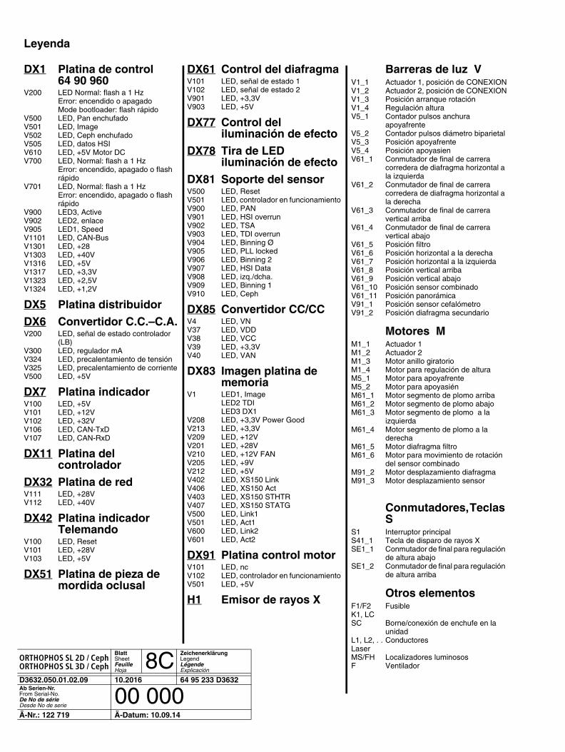
Leyenda
DX1 Platina de control 64 90 960
V200 LED Normal: flash a 1 HzError: encendido o apagadoMode bootloader: flash rápido
V500 LED, Pan enchufadoV501 LED, Image V502 LED, Ceph enchufadoV505 LED, datos HSI V610 LED, +5V Motor DCV700 LED, Normal: flash a 1 Hz
Error: encendido, apagado o flash rápido
V701 LED, Normal: flash a 1 HzError: encendido, apagado o flash rápido
V900 LED3, ActiveV902 LED2, enlace V905 LED1, SpeedV1101 LED, CAN-BusV1301 LED, +28V1303 LED, +40VV1316 LED, +5VV1317 LED, +3,3VV1323 LED, +2,5VV1324 LED, +1,2V
DX5 Platina distribuidor
DX6 Convertidor C.C.–C.A.V200 LED, señal de estado controlador
(LB) V300 LED, regulador mAV324 LED, precalentamiento de tensiónV325 LED, precalentamiento de corrienteV500 LED, +5V
DX7 Platina indicadorV100 LED, +5VV101 LED, +12VV102 LED, +32VV106 LED, CAN-TxDV107 LED, CAN-RxD
DX11 Platina delcontrolador
DX32 Platina de redV111 LED, +28VV112 LED, +40V
DX42 Platina indicadorTelemando
V100 LED, ResetV101 LED, +28VV103 LED, +5V
DX51 Platina de pieza demordida oclusal
DX61 Control del diafragmaV101 LED, señal de estado 1V102 LED, señal de estado 2V901 LED, +3,3VV903 LED, +5V
DX77 Control del iluminación de efecto
DX78 Tira de LED iluminación de efecto
DX81 Soporte del sensorV500 LED, ResetV501 LED, controlador en funcionamientoV900 LED, PANV901 LED, HSI overrunV902 LED, TSAV903 LED, TDI overrunV904 LED, Binning ØV905 LED, PLL lockedV906 LED, Binning 2V907 LED, HSI DataV908 LED, izq./dcha.V909 LED, Binning 1V910 LED, Ceph
DX85 Convertidor CC/CCV4 LED, VNV37 LED, VDDV38 LED, VCCV39 LED, +3,3VV40 LED, VAN
DX83 Imagen platina de memoria
V1 LED1, ImageLED2 TDILED3 DX1
V208 LED, +3,3V Power GoodV213 LED, +3,3VV209 LED, +12VV201 LED, +28VV210 LED, +12V FANV205 LED, +9VV212 LED, +5VV402 LED, XS150 LinkV406 LED, XS150 ActV403 LED, XS150 STHTRV407 LED, XS150 STATGV500 LED, Link1V501 LED, Act1V600 LED, Link2V601 LED, Act2
DX91 Platina control motorV101 LED, ncV102 LED, controlador en funcionamientoV501 LED, +5V
H1 Emisor de rayos X
Barreras de luz VV1_1 Actuador 1, posición de CONEXIONV1_2 Actuador 2, posición de CONEXIONV1_3 Posición arranque rotaciónV1_4 Regulación alturaV5_1 Contador pulsos anchura
apoyafrenteV5_2 Contador pulsos diámetro biparietalV5_3 Posición apoyafrenteV5_4 Posición apoyasienV61_1 Conmutador de final de carrera
corredera de diafragma horizontal a la izquierda
V61_2 Conmutador de final de carrera corredera de diafragma horizontal a la derecha
V61_3 Conmutador de final de carrera vertical arriba
V61_4 Conmutador de final de carrera vertical abajo
V61_5 Posición filtroV61_6 Posición horizontal a la derechaV61_7 Posición horizontal a la izquierdaV61_8 Posición vertical arribaV61_9 Posición vertical abajoV61_10 Posición sensor combinadoV61_11 Posición panorámicaV91_1 Posición sensor cefalómetro V91_2 Posición diafragma secundario
Motores MM1_1 Actuador 1 M1_2 Actuador 2 M1_3 Motor anillo giratorioM1_4 Motor para regulación de alturaM5_1 Motor para apoyafrenteM5_2 Motor para apoyasiénM61_1 Motor segmento de plomo arribaM61_2 Motor segmento de plomo abajoM61_3 Motor segmento de plomo a la
izquierdaM61_4 Motor segmento de plomo a la
derechaM61_5 Motor diafragma filtroM61_6 Motor para movimiento de rotación
del sensor combinadoM91_2 Motor desplazamiento diafragmaM91_3 Motor desplazamiento sensor
Conmutadores, Teclas S
S1 Interruptor principalS41_1 Tecla de disparo de rayos XSE1_1 Conmutador de final para regulación
de altura abajoSE1_2 Conmutador de final para regulación
de altura arriba
Otros elementosF1/F2 FusibleK1, LCSC Borne/conexión de enchufe en la
unidadL1, L2, . . ConductoresLaser MS/FH Localizadores luminososF Ventilador
loqelmelp=pi=Oa=L=̀ ÉéÜloqelmelp=pi=Pa=L=̀ ÉéÜ
BlattSheetFeuilleHoja
8CZeichenerklärung Legend LégendeExplicación
D3632.050.01.02.09 10.2016 64 95 233 D3632Ab Serien-Nr.From Serial-No.De No de sérieDesde No de serie
00 000Ä-Nr.: 122 719 Ä-Datum: 10.09.14


ûåÇÉêìåÖÉå=áã=wìÖÉ=íÉÅÜåáëÅÜÉê=tÉáíÉêÉåíïáÅâäìåÖ=îçêÄÉÜ~äíÉåKtÉ=êÉëÉêîÉ=íÜÉ=êáÖÜí=íç=ã~âÉ=~åó=~äíÉê~íáçåë=ïÜáÅÜ=ã~ó=ÄÉ=êÉèìáêÉÇ=ÇìÉ=íç=íÉÅÜåáÅ~ä=áãéêçîÉãÉåíëKpçìë=ê¨ëÉêîÉ=ÇÉ=ãçÇáÑáÅ~íáçåë=ÇìÉë=~ì=éêçÖê≠ë=íÉÅÜåáèìÉKoÉëÉêî~Ççë=äçë=ÇÉêÉÅÜçë=ÇÉ=ãçÇáÑáÅ~Åáμå=Éå=îáêíìÇ=ÇÉä=éêçÖêÉëç=í¨ÅåáÅçK
= péê~ÅÜÉW=ÇÉìíëÅÜI=ÉåÖäáëÅÜI=Ñê~åò∏ëáëÅÜI=ëé~åáëÅÜ mêáåíÉÇ=áå=dÉêã~åóaPSPOKMRMKMNKMOKMV===NMKOMNS ûKJkêKW= NOO=TNV fãéêáã¨=Éå=^ääÉã~ÖåÉ
páêçå~=aÉåí~ä=póëíÉãë=dãÄe=
áå=íÜÉ=rp^Wc~Äêáâëíê~≈É=PN páêçå~=aÉåí~ä=póëíÉãë=ii` _ÉëíÉääJkêKaJSQSOR=_ÉåëÜÉáã QUPR=páêçå~=aêáîÉI=pìáíÉ=NMM lêÇÉê=kç SQ=VR=OPP=aPSPOdÉêã~åó `Ü~êäçííÉI=k`=OUOTP kçK=ÇÉ=ÅÇÉKïïïKëáêçå~KÇÉ rp^ kç=ÇÉ=éÉÇáÇç