Embed Size (px)
DESCRIPTION
Â
Citation preview

Studio
A I RSemester 1 2016
Geoffrey Goerling

“PICture This”698748 Geoffrey Goerling
Semester 1 2016
Studio Leader: Caitlyn Parry
CONTENTS4 -5 INTRODUCTION
6 A - CONCEPTUALISATION
8-11 - A01 DESIGN FUTURING
12-15 - A02 COMPUTATION & COMPUTERISATION
6-19 - A03 GENERATION & COMPOSITION
20-21 - ALGORITHMIC SKETCH EXEMPLARS
22 - CONCLUSION
23 - LEARNING OUTCOMES
24 - FIGURES
24-25 - REFERENCES
26 B - CRITERIA DESIGN
28-29 B1 – RESEARCH FIELD
30-35 B2 – CASE STUDY 1.0
36-41 B3 – CASE STUDY 2.0
42-49 B4 – TECHNIQUE DEVELOPMENT
50-53 B5 – PROTOTYPING
54-59 B6 – TECHNIQUE PROPOSAL
60-61 B7– LEARNING OUTCOMES
62-67 – APPENDICES
68 – FIGURES
69 - REFERENCES
70 C - DETAIL DESIGN
72 – 79 C1 – DESIGN CONCEPT
80 - 87 C2 – TECTONIC DETAIL
88 – 97 C3 – FINAL OUTCOME
98 – 99 C4 – CONCLUSION

4 CONCEPTUALISATION
It is redundant to restate that we must rapidly adapt our society in order to avoid becoming the catalyst of a worldwide ecological collapse. This is broadly accepted, instead action must replace resignation, cynicism and denial as the dominant response to this premise. I therefore intend my design career to be a search for truly sustainable modes of living, and an investigation of the role new building typologies play in this.
The term sustainability has been misappropriated and muddied by marketing teams, coming to mean slightly less environmentally damaging. I instead use it in its original sense. Fundamentally, way of life, and the built environemnt which facilitates it, are sustainable if everyone could live that way forever. Rigorous adherence to this principle must become the norm in the 21st century. Achieving net zero environmental impact is as necessary to any development as structural integrity. This will require designers to collaborate with people from a variety of disciplines. While sustainable outcomes are not a sufficient condition for good design, as they are so widely ignored, or denigrated to an optional afterthought it is justifiable to emphasise them as a key element of it.
These principles shall shape my studio air proposal this semester. I intend to consider the environmental impact of my work throughout all stages of the design process, from conceptualisation to the resolution of details, rather than tack on a few insipid measures as an afterthought. I also hope to draw on knowledge from outside of the architectural discipline. In doing so I hope to greatly further as yet non-existent parametric modelling skills, test and refine my design philosophy by investigating the role of parametric thinking in achieving sustainable outcomes, and arrive at a design outcome I can be truly proud of.
INTRODUCTION
CONCEPTUALISATION 5
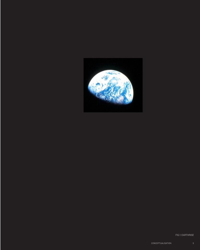
FIG.1: EARTHRISE
6 CONCEPTUALISATION
PART A
CONCEPTUALISATION

CONCEPTUALISATION 7
A01
DESIGN FUTURING

8 CONCEPTUALISATION
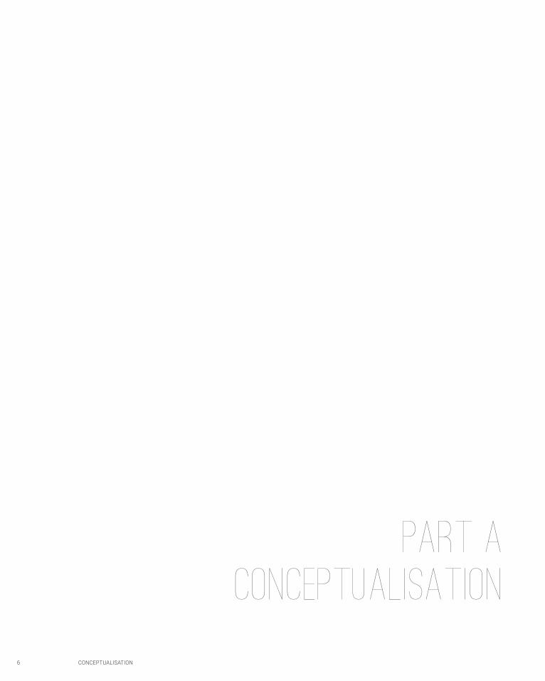
As a full scale built project the Ganterbein Winery Façade Represents an important step in bridging the gap between digital design and material reality, and therefore realising the full potential of parametric design. The brick panels which make up the façade where prefabricated using an industrial robot to lay each brick with precise orientation and spacing.1.1 The ability to these ‘dexterous’ robots read digital parameters directly removes the need to convey this complex information through drawings to workmen. This consequently allows for the cost effective manufacturing of complex bespoke elements and the realisation of otherwise fantastic digital scemes.1.2
This project is not an example of ‘design futuring’ as it neither engenders sustainable practices nor slows defuturing by significantly improving environmental performance.1.3 robotic manufacturing is employed to facilitate aesthetic expression, with the designer likening bricks to pixels composing a digital image, an image which is especially interesting for its three dimensionality which leads to interplay with natural light and user position.1.4 The technology developed during the project has great potential to be adopted for design futuring however. One of the many possible examples in tropical passive design, where robotic arms could be used to create complex permeable surfaces which respond precisely to the unique conditions of a sight at a reasonable cost and thus exclude direct sunlight while maximising passive ventilation.
GANTERBIEN WINERY FACADE
GRAMAZIO + KOHLER
CONCEPTUALISATION 9
FIG.2: GANTERBEIN WINERY INTERIOR & FACADE PATTERNING
10 CONCEPTUALISATION
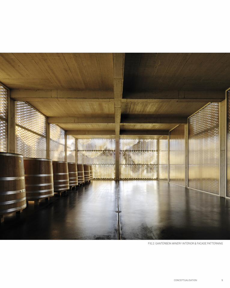
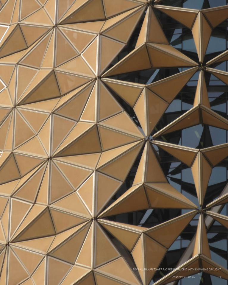
Rather than enclose Al Bahar Tower in a standard glass curtain wall inappropriate to the UAE’s harsh climate AEDAS examined Mashrabiya screens in local vernacular architecture to create an innovative alternative solution.1.5 They devised an adaptive façade shading system consisting of tessellating translucent umbrella like screens which open or close individually in response to the suns position and strength. Their solution also clearly references geometric patterns in Islamic art and is therefore rooted in both the culture and environment of its location.
The idea of an adaptive façade itself, which is optimised within given parameters to in response to environmental conditions, is not revolutionary. Jean Nouvel’s Institut du Monde Arabe employed a similar system in the late 1980s,1.6 and the use of manually operable shading devices in vernacular architecture is commonplace. AEDAS however link this system to sensors via the Al Bahar towers BMS, creating an intelligent façade which responds to environmental stimuli like a biological organism.1.7 This has resulted 50% reductions in solar heat gain, improved natural lighting, reduced glare and therefore greatly reduced CO2 emissions and improved IEQ.1.8 The implementation of an adaptive façade on this scale and its integration with sensors was therefore a major step in the ideas evolution. Furthermore it represents the embedding of algorithmic logic in the physical world, as based on a series of environmental inputs an output condition is optimised within given parameters.
This exercise in design futuring was enabled by the use of software providing ‘feedback loops’ which accurately modelled how changes in the design, or outcome priorities, effected the buildings performance.1.9 This allowed the design of façade shading elements and the towers form itself to be optimised to site conditions.
AEDAS
AL BAHAR TOWERS FACADE
CONCEPTUALISATION 11
FIG.3: AL BAHAR TOWER FACADE UNFOLDING WITH CHANGING DAYLIGHT

A02 COMPUTATION
An Argument
CONCEPTUALISATION 12
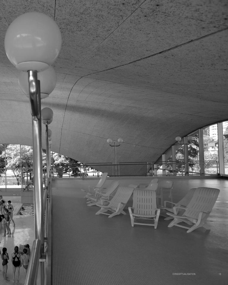
FIG.4: ISLER SHELL ROOF OF BRUGG INDOOR SWIMMING POOL
CONCEPTUALISATION 13
14 CONCEPTUALISATION
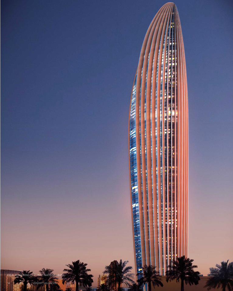
FIG.5: RENDERING OF KUWAIT NATIONAL BANK
CONCEPTUALISATION 15
Kalay argues that the design process involves three stages. Problem analysis is the formulation of a design intent by identifying goals, problems and constraints to address. This is followed by solution synthesis, where designers formulate potential solutions, and Evaluation where these are tested against the initial parameters.2.1 The benefits of using computers in architecture are entirely dependent on how they are integrated into this process.
Computerisation, the use of computers to document ideas generated by conventional means at the solution synthesis stage, represents only a minor refinement to established design processes.2.2 This is undoubtedly time and labour saving, especially when dealing with freeform geometry. It therefore allows the realisation of otherwise prohibitively formal complex forms such as Gehry’s iconic Bilbao Guggenheim.2.3 However, as ideas are generated in analogue space it does not extend what was already humanly conceivable.
Conversely computation, or the use of algrithmic logic as a form finding aide in solution synthesis,2.4 opens boundless new horizons for architecture. Computation has the potential to redefine the design process, the nature of practice and greatly further performative design through the symbiosis of distinct human and digital forms of intelligence.
In the pre digital age solution synthesis relied on an ‘intuitive leap’2.3 or simple analogue form finding. For example Heinz Isler pioneered creation of thin catenary membranes which acted in pure compression by inverting plaster casts of membranes in pure tension.2.4 This analogue method of computation derived
dominant formal concepts at the solution synthesis stage from forces acting on a material rather than Isler’s arbitrary whim. However the process was prohibitively time consuming, suited only to very particular typologies requiring large single volumes, and required such precision that it has never been successfully replicated.2.5
The use of computers in architectural design allows form much more complex computation of design outcomes. Parametric design software can rapidly generate multiple design iterations for evaluation. For example Foster + Partners developed a parametric model which integrated several objective design performance parameters when designing the Kuwait National Bank Headquarters.2.6 The skyscraper’s complex form emerged from feedback loop between the evaluation of structural and energy performance of each solution synthesis, with the fins on the towers east an west façades providing both shading and structural support.2.7
This symbiosis between the data processing capabilities of computers and human creative intuition enabled rigorous performance based design as a means of design futuring. Furthermore it simultaneously redefining the role of the designer as a formulator of problems and assessor of digital formal responses, rather than a generator of form. It therefore de-emphasises their role in the solution syntheses stage of design in favour of the other two, and leads to outcomes that human intelligence could not have conceived unaided. Coupled with advances in digital fabrication it may also return architects to their traditional role of master craftspeople, able to create bespoke artefacts themselves by rationalising and materialising the digital.
16 CONCEPTUALISATION
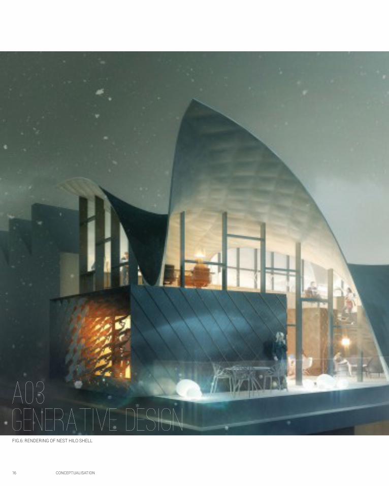
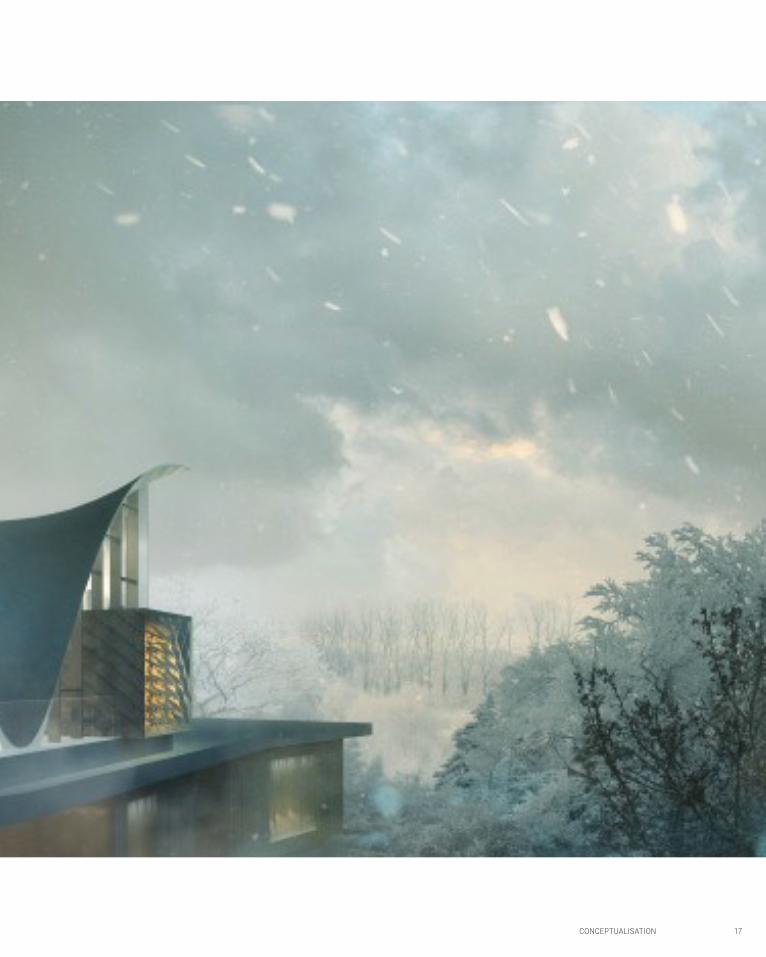
A03GENERATIVE DESIGNFIG.6: RENDERING OF NEST HILO SHELL
CONCEPTUALISATION 17
A03GENERATIVE DESIGN
18 CONCEPTUALISATION
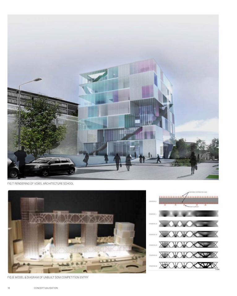
FIG.7: RENDERING OF VOXEL ARCHITECTURE SCHOOL
FIG.8: MODEL & DIAGRAM OF UNBUILT SOM COMPETITION ENTRY

CONCEPTUALISATION 19
Traditional architectural design is compositional, or top down, with the architect imposing a chosen system of formal relationships onto the building. These compositional systems can pragmatic, such as composing stairs conforming to a system of anthropometric relationships. Predominantly However, compositional languages such as the beaux arts planning or the picturesque have been used to impart subjective representational and aesthetic value onto buildings.
Generative design represents an alternative to this established mode of design practice. Forms are instead generated ‘bottom up’ by the repetition of a simple set of algorithmic rules from which a complex order emerges. The viability mode of this mode design has been greatly increased by the iterative power of parametric modelling software and, as outlined in A02, it leads designers to focus on problem analysis and evaluation.
Generative design presents exciting opportunities for structural systems, with optimised outcomes able to be developed using evolutionary process. SOM employed a generative process to design the structural bracing of the enormous cantilever in the unrealised competition entry pictured opposite.3.1 Furthermore the structurally optimised shells and floor slabs developed for the Nest/Hilo reseach pavilion push concrete to the limit of its structural capabilities. The structures 2cm thin concrete slabs are reinforced by a web fins which trace lines of force.3.2 This has resulted 70% savings in materials and weight compared to using conventional slabs for the project.3.3 In both these projects the fluid curves generate have led to a gothicesque convergence of expressiveness structural rationality.3.4
A generative design process based on biological evolution was used to create the programmatic layout of LAVA and Bollinger + Gromann’s Hochschule fur Technik architecture building in Stuttgart.3.5 sheer walls and voids where distributed randomly across a Dom-Ino like platform
and piloti grid to generate 50 design iterations.3.6 These where then evaluated against structural and programmatic criteria, with the most successful being chosen as the basis algorithmic blending (or reproduction). This process was repeated for 200 “generations” until an optimal solution for the set criteria was derived.3.7 While this represents an interesting experiment with design methodology it is highly questionable whether the algorithm developed to lay out the walls could replicate the subtle understanding of spatial qualities and sequencing of a skilled designer
It is unfair however to dismiss generative design’s capacity to move beyond structural rationalisation or patterning based at such an embryonic stage in its development based on one unimaginative application to a tired tectonic. As Oxman and Oxman have argued, I believe it is ultimately possible for generational design to create a ‘second nature’. 3.8 The infinite iterative power parametric design used in a feedback loop with sophisticated performance analysis software can generate optimised form from structural and environmental concerns. Alongside the tectonic and material systems of Gramazio and Kohler described in A01, this enables the creation of a truly ecological architecture which evolves in response to its environment, and is therefore a powerful design futuring tool.
I believe the architects will not be superseded by coding however, and will integral to evaluating and humanising generative design. Through their own study and subjective human experience of space architects will continue to understand the built environment in ways it is inconceivable for a computer too. The most powerfully atmospheric buildings I have ever visited have all been created with a sensitive understanding of the interplay of light and material texture, scale and numerous other factors beyond algorithmic comprehension. Architects therefore remain essential to ensuring that humanism is not abandoned to the generative process.
20 CONCEPTUALISATION
ALGORITHMIC SKETCHES
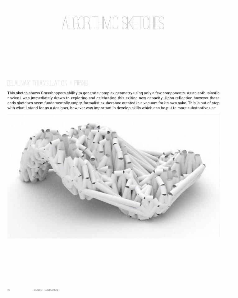
Delaunay Triangulation + Piping
This sketch shows Grasshoppers ability to generate complex geometry using only a few components. As an enthusiastic novice I was immediately drawn to exploring and celebrating this exiting new capacity. Upon reflection however these early sketches seem fundamentally empty, formalist exuberance created in a vacuum for its own sake. This is out of step with what I stand for as a designer, however was important in develop skills which can be put to more substantive use
CONCEPTUALISATION 21
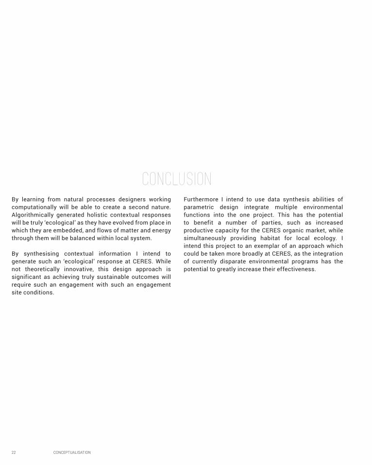
This sketch pushes beyond the what was taught in tutorials by using data culling to morph different geometry into alternating boxes on a surface. It represents the most developable geometry I have generated, as I was aiming to create something which could be woven from plywood. Furthermore it illustrates the generative nature of exploratory parametric design, as the final form differs significantly from my initial idea.
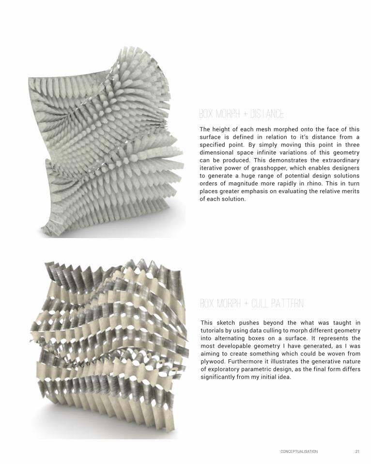
The height of each mesh morphed onto the face of this surface is defined in relation to it’s distance from a specified point. By simply moving this point in three dimensional space infinite variations of this geometry can be produced. This demonstrates the extraordinary iterative power of grasshopper, which enables designers to generate a huge range of potential design solutions orders of magnitude more rapidly in rhino. This in turn places greater emphasis on evaluating the relative merits of each solution.
Box Morph + Distance
Box Morph + Cull Pattern
CONCLUSIONBy learning from natural processes designers working computationally will be able to create a second nature. Algorithmically generated holistic contextual responses will be truly ‘ecological’ as they have evolved from place in which they are embedded, and flows of matter and energy through them will be balanced within local system.
By synthesising contextual information I intend to generate such an ‘ecological’ response at CERES. While not theoretically innovative, this design approach is significant as achieving truly sustainable outcomes will require such an engagement with such an engagement site conditions.
Furthermore I intend to use data synthesis abilities of parametric design integrate multiple environmental functions into the one project. This has the potential to benefit a number of parties, such as increased productive capacity for the CERES organic market, while simultaneously providing habitat for local ecology. I intend this project to an exemplar of an approach which could be taken more broadly at CERES, as the integration of currently disparate environmental programs has the potential to greatly increase their effectiveness.
22 CONCEPTUALISATION
learning OUTCOMESOver only the last few weeks my knowledge of the parametric design process and its implications for architectural practice has increased greatly.
Previously I looked at it with ignorant distrust, thinking it was a kind of arbitrary formalism driven only by the desire to create complex and organic geometry. Engaging with academic digital design theory for the first time through both set readings and my own research, especially the work of Oxman & Oxman, Foster + Partners and Gramazio + Kohler has dispelled these notions. I now understand parametric design to be a process, rather than a formal outcome. This process has the ability to embed complex contextual and structural information into digital models and therefore facilitates sophisticated site responses.
By doing parametric sketch exercises alongside this
theory I am slowly coming to grips with the changes in thinking parametric design entails. Rather than focusing composing form I have been encourage to take an iterative approach and evaluate the relative merits of experimental outcomes. Parametric sketching has also required me to think in terms of data flows and networks, and frame simple problems so that they are able to be solved.
This knowledge would have been very helpful in my last design studio. As I was deforming complex organic geometries in response to site conditions a simple parametric massing modelling would have been the ideal tool to explore the relative merits of different design iterations. This would have allowed for a more resolved reasoned site response, and by saving time in the early stages of design allowed for a more refined final outcome.
CONCEPTUALISATION 23
24 CONCEPTUALISATION
FIGURESFigure 1: William Anders, Earthrise, 1968, Photograph, < http://www.nasa. gov/multimedia/imagegallery/ image_feature_1249.html> [accessed 6 March 2016]
Figure 2: Ralph Feiner, Ganterbien Winery Interior, 2006, Photograph , < http://www.archdaily. com/260612/winery-gantenbein-gramazio-kohler-bearth-deplazes-architekten> [accessed 6 March 2016]
Figure 3: Uncredited, Torres Al Bahar, 2013, Photograph , < http:// es.wikiarquitectura.com/index.php/Torres_Al_Bahar> [accessed 7 March 2016]
Figure 4: User Contribution, Isler Shell Roof of the indoor swimming pool in Brugg, 2009, Photograph, <http:// commons.wikimedia.org/wiki/File:Hallenbad_Brugg_innen_01_09.jpg> [accessed 14 March 2016]
Figure 5: Foster + Partners, Kuwait National Bank Headquarters, 2013, Rendering , < http://www.f osterandpartners.com/projects/national-bank-of-kuwait/> [accessed 15 March 2016]
Figure 6: Hilo Architecture, Hilo Exterior, 2013, Rendering < http://hilo.arch.ethz.ch/> [accessed 17 March 2016]
Figure 7: LAVA, Exterior rendering, 2009, Rendering , < http:/?www.l-a-v-a.net/ projects/stuttgart-university-voxel/> [accessed 17 March 2016]
Figure 8: SOM, Commercial Development Project, 2011, Model and Diagram, From “Structural Emergence: Architectural and Structural Design Collaboration at SOM”, Architectural design 83.2 (March 2013), pp. 48–55.
.1 Fabio Gramazio, Matthias Kohler and Jan Willmann, ‘Authoring Robotic Proccess’, Architectural Design, 84.3 (May 2014), 14-21.
1.2 Ibid.
1.3 Design Futuring: Sustainability, Ethics and New Practice, ed. by Tony Fry, (Oxford: Berg, 2009) pp. 1-16.
1.4 Fabio Gramazio, ‘Winery Gantenbein / Gramazio & Kohler + Bearth & Deplazes Architekten’, in Archdaily < http://www.archdaily.com/260612/winery-gantenbein-gramazio-kohler-bearth-deplazes-architekten
1.5 Christian Derix, Judit Kimpian, Abdulmarid Karanouh and Josh Mason, ‘Feedback Architecture’, in Architectural Design, 81.6 (November 2011), 36-43.
1.6 Tim Winstanley, ‘Institut du Monde Arabe / Jean Nouvel, Architecture-Studio, Pierre Soria and Gilbert Lezenes’, in Archdaily < http://www.archdaily.com/162101/ad-classics-institut-du-monde-arabe-jean-nouvel>
1.7 Council on Tall Buildings and Urban Habitation, ‘Al Bahar Towers’, in Best Tall Buildings 2012 ed. by Anthony Wood, (Chicago: Routledge, 2012), 172 -177.
11.8 Ibid.
1.9 Ibid.
REFERENCES
CONCEPTUALISATION 25
2.1 Yehuda Kalay, Architecture’s New Media: Principles, Theories, and Methods of Computer-Aided Design, (Cambridge, MA: MIT Press, 2004), pp. 5-25.
2.2 Brady Peters, ‘Computation Works: The Building of Algorithmic Thought’, Architectural Design, 83.2 (March 2013), 8-15.
2.3 Theories of the Digital in Architecture ed. by Rivka Oxman and Robert Oxman, (London; New York: Routledge, 2014), pp. 1–10
2.4 Peters, p. 8-15.
2.3 Kalay, p. 5-25.
2.4 John Chilton, ‘Heinz Isler’s Infinite Spectrum: Form Finding in Design’, Architectural Design, 80.4 (July 2010), 64-71.
2.5 Ibid.
2.6 Dusanka Popovska, ‘Integrated Computational Design: National Bank of Kuwait Headquarters’, Architectural Design, 83.2 (March 2013), 34-35.
2.7 Ibid
3.1 Keith Besserud, Neil Katz and Alessandro Beghini “Structural Emergence: Architectural and Structural Design Collaboration at SOM”, Architectural Design 83.2 (March 2013), 48–55.
3.2 Philippe Block, “Parametricism’s Structural Congeniality”, Architectural Design 86.2 (March 2016), 68-75.
3.3 Ibid
3.4 Ibid
3.5 Klaus Bollinger, Manfred Grohmann and Oliver Tessmann “Structured Becoming: Evolutionary Processes in Design Engineering”, Archiectural Design 80.4 (July 2010), 34-39.
3.6 Ibid
3.7 Ibid
3. 8 Theories of the Digital in Architecture ed. by Rivka Oxman and Robert Oxman, eds. (London; New York: Routledge, 2014), pp. 1–10

26 CRITERIA DESIGN
PART BCriteria Design

CRITERIA DESIGN 27
B1RESEARCH Field
28 CRITERIA DESIGN
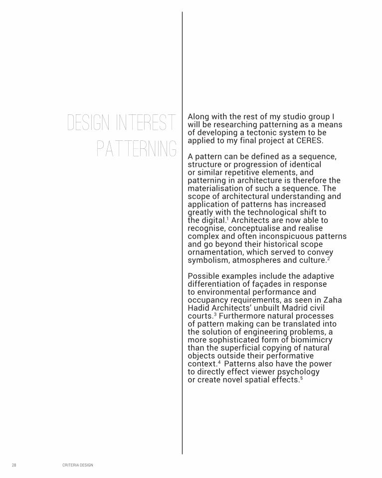
Along with the rest of my studio group I will be researching patterning as a means of developing a tectonic system to be applied to my final project at CERES.
A pattern can be defined as a sequence, structure or progression of identical or similar repetitive elements, and patterning in architecture is therefore the materialisation of such a sequence. The scope of architectural understanding and application of patterns has increased greatly with the technological shift to the digital.1 Architects are now able to recognise, conceptualise and realise complex and often inconspicuous patterns and go beyond their historical scope ornamentation, which served to convey symbolism, atmospheres and culture.2
Possible examples include the adaptive differentiation of façades in response to environmental performance and occupancy requirements, as seen in Zaha Hadid Architects’ unbuilt Madrid civil courts.3 Furthermore natural processes of pattern making can be translated into the solution of engineering problems, a more sophisticated form of biomimicry than the superficial copying of natural objects outside their performative context.4 Patterns also have the power to directly effect viewer psychology or create novel spatial effects.5
patterning
DESIGN interest
CRITERIA DESIGN 29
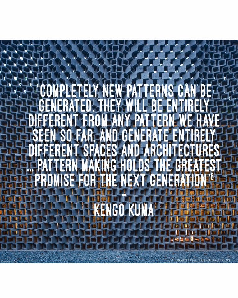
“Completely new Patterns can be generated. They will be entirely
different from any pattern we have seen so far, and generate entirely
different spaces and architectures ... pattern making holds the greatest
promise for the next generation”6
-KEngo Kuma
FIG.19 AU OFFICE & EXHIBITION SPACE FACADE

30 CRITERIA DESIGN
B1Case Study 1.0
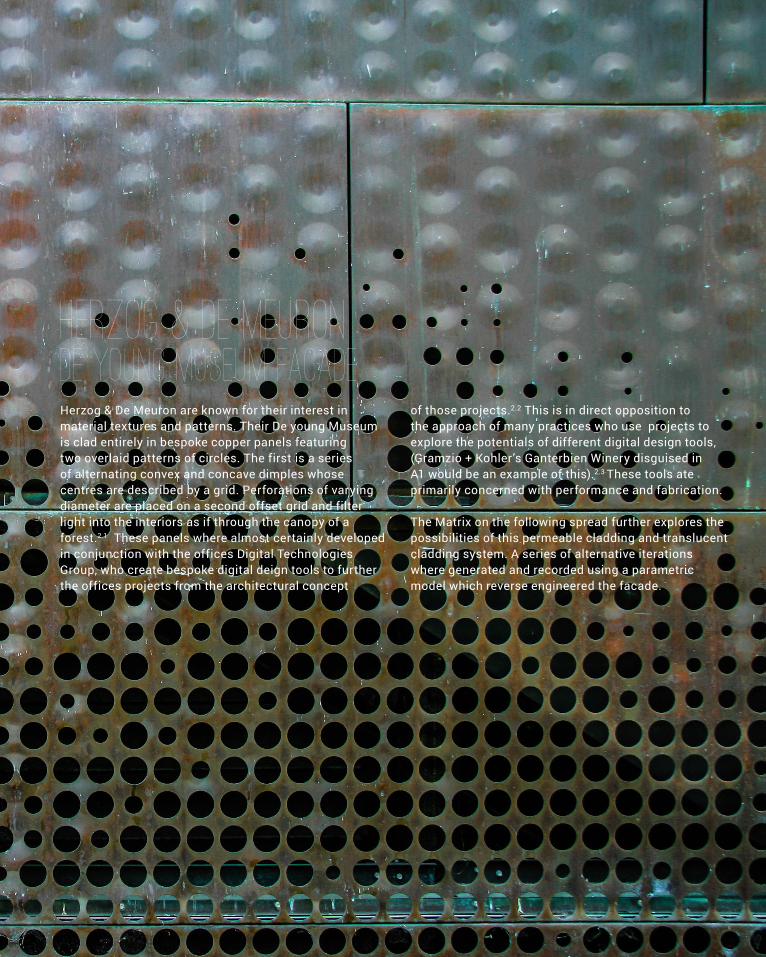
FIG.10 DE YOUNG MUSEUM FACADE
CRITERIA DESIGN 31
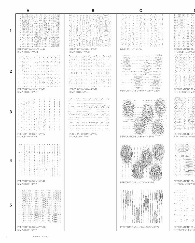
HErzog & De MEuron DE young Museum FaCadeHerzog & De Meuron are known for their interest in material textures and patterns. Their De young Museum is clad entirely in bespoke copper panels featuring two overlaid patterns of circles. The first is a series of alternating convex and concave dimples whose centres are described by a grid. Perforations of varying diameter are placed on a second offset grid and filter light into the interiors as if through the canopy of a forest.2.1 These panels where almost certainly developed in conjunction with the offices Digital Technologies Group, who create bespoke digital deign tools to further the offices projects from the architectural concept
of those projects.2.2 This is in direct opposition to the approach of many practices who use projects to explore the potentials of different digital design tools, (Gramzio + Kohler’s Ganterbien Winery disguised in A1 would be an example of this).2.3 These tools ate primarily concerned with performance and fabrication.
The Matrix on the following spread further explores the possibilities of this permeable cladding and translucent cladding system. A series of alternative iterations where generated and recorded using a parametric model which reverse engineered the facade.
32 CRITERIA DESIGN
A B C D
1
2
3
4
5
PERFORATIONS U=50 V=44 DIMPLES U= 17 V=14
DIMPLES U= 11 V= 16 PERFORATIONS SF= 0.087 RF= 0.543 U=50 V=45
PERFORATIONS U= 28 V=31 DIMPLES U= 12 V=13
PERFORATIONS U= 22 V=22 DIMPLES U= 10 V=8 PERFORATIONS U= 55 V= 12 SF = 0.336 PERFORATIONS SF = 0.207
RF = 0.653 U=23 V=23PERFORATIONS U= 49 V=28 DIMPLES U= 6 V= 4
PERFORATIONS U= 16 V=22 DIMPLES U= 8 V=13 PERFORATIONS U= 55 V= 14 SF=1
PERFORATIONS SF = 0.119 RF= 1.464 U=38 V=21
PERFORATIONS U= 55 V=12 DIMPLES U= 17 V= 4
PERFORATIONS U= 16 V=48 DIMPLES U= 18 V=4 PERFORATIONS U= 27 V= 40 SF=1 PERFORATIONS SF= 0.119
RF= 0.280 U=38 V=50
PERFORATIONS U= 47 V=48 DIMPLES U= 16 V=4
PERFORATIONS U= 18 V= 93 SF= 0.277 PERFORATIONS SF = 0.119 RF= 0.371 U=18 V=13

CRITERIA DESIGN 33
D E F G
A: ORIGINAL ALGORITHMB: INVERT IMAGE SAMPLEC: SINGLE GRIDD: ELLIPTICAL PERFORATIONSE: ROTATED ELLIPTICAL PERFORATIONSF: POLYGONAL PERFORATIONSG: POLYGONAL PERFORATIONS & DIMPLES
V: NUMBER OF GRID POINTS IN V DOMAINU: NUMBER OF GRID POINTS IN V DOMAINSF: SCALE FACTORRF: ELLIPSE LONG/SHORT RADIUS RATIO FACTORR: ROTATION (DEGREES)VE: NUMBER OF VERTICES
PERMEABILITYRATIO OF VOIDS TO SOLIDS
DEVELOPABILITYSUCCESFUL ITERATIONS MUST BE DEVELOPABLE
PERFORATIONS SF= 0.087 RF= 0.543 U=50 V=45
PERFORATIONS SF= 0.119 RF= 0.371 U=18 V=13 R = 135
PERFORATIONS SF = 0.113 U=42 V=37 VE= 4
PERFORATIONS SF = 0.314 U=18 V=12 VE=4 DIMPLES SF= 0.088 U=7 V=8 VE= 4
PERFORATIONS SF= 0.131 U=30 V=19 VE=5 DIMPLES SF = 0.088 U=7 V=8 VE=3
PERFORATIONS SF = 0.207 RF = 0.653 U=23 V=23
PERFORATIONS SF= 0.229 RF= 0.371 U=18 V=13 R = 125
PERFORATIONS SF= 0.2 U=42 V=37 VE= 4
PERFORATIONS SF = 0.119 RF= 1.464 U=38 V=21
PERFORATIONS SF= 0.121 RF= 0.371 U=47 V=50 R = 125
PERFORATIONS SF = 0.314 U=18 V=12 VE = 4
PERFORATIONS SF= 0.119 RF= 0.280 U=38 V=50
PERFORATIONS SF= 0.121 RF= 0.371 U=47 V=50 R = 21
PERFORATIONS SF= 0.191 U=35 V=17 VE=3
PERFORATIONS SF = 0.119 RF= 0.371 U=18 V=13
PERFORATIONS SF= 0.153 RF= 0.121 U=47 V=29 R = 41
PERFORATIONS SF = 0.314 U=18 V=12 VE= 5
MAtrix ExplorationSERIES
KEY
ASSESSMENT CRITEREA
34 CRITERIA DESIGN
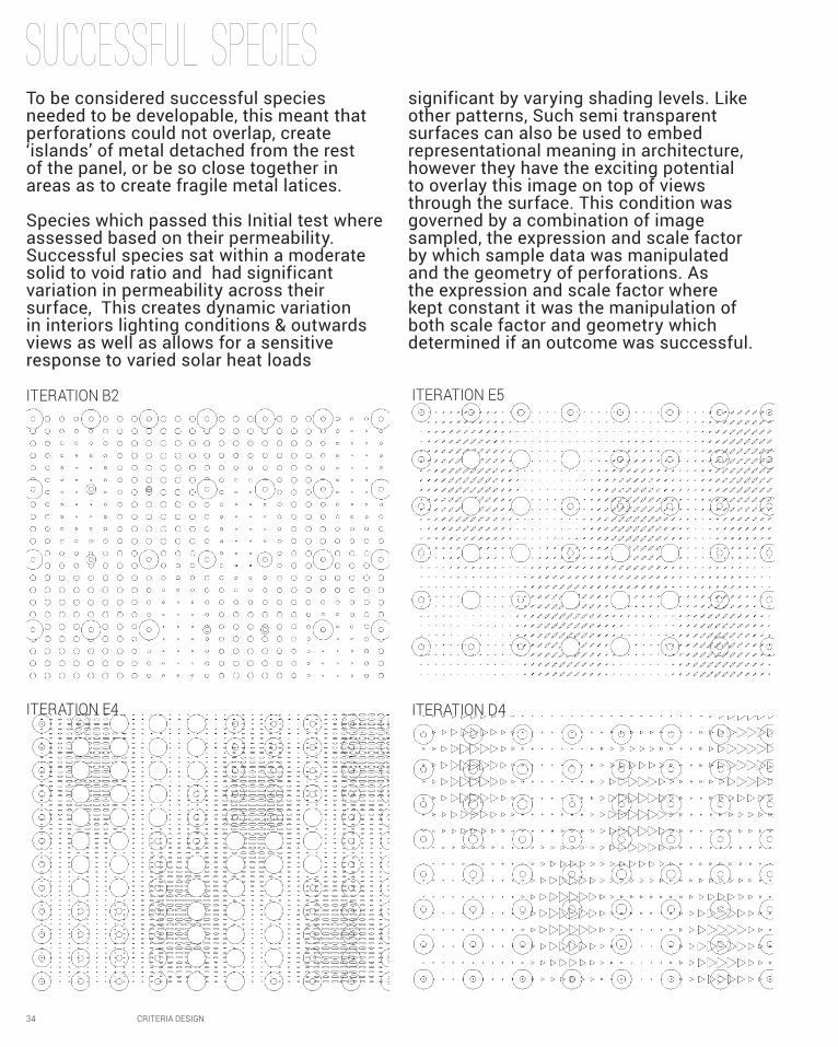
Successful Species
ITERATION E5
ITERATION E4
ITERATION B2
ITERATION D4
To be considered successful species needed to be developable, this meant that perforations could not overlap, create ‘islands’ of metal detached from the rest of the panel, or be so close together in areas as to create fragile metal latices.
Species which passed this Initial test where assessed based on their permeability. Successful species sat within a moderate solid to void ratio and had significant variation in permeability across their surface, This creates dynamic variation in interiors lighting conditions & outwards views as well as allows for a sensitive response to varied solar heat loads
significant by varying shading levels. Like other patterns, Such semi transparent surfaces can also be used to embed representational meaning in architecture, however they have the exciting potential to overlay this image on top of views through the surface. This condition was governed by a combination of image sampled, the expression and scale factor by which sample data was manipulated and the geometry of perforations. As the expression and scale factor where kept constant it was the manipulation of both scale factor and geometry which determined if an outcome was successful.
CRITERIA DESIGN 35
Further Speculation& Critical ReflectionMy explorations focused on modifying the geometry of the De Young façade while retaining its original application, as a diaphanous, permeable cladding patterned with abstract geometry. Consequently they remained extremely limited in their range of formal outcomes and applications. While iterations where geometry overlapped came to resemble patterns applied to a solid surface, and others with polygonal or elliptical perforations acquired a sense of dynamism the original lacked they remained essentially two dimensional surfaces.
This is likely a result of the methodology I employed, focusing on manipulating single parameter or component at a time,
rather than working holistically with the function. This meant that generating many iterations did not significantly vary the grasshopper definition, and therefore its output geometry. My focus on the surface perforations, rather than its three dimensional dimples further limited outcomes as I did not explore the surfaces three dimensional properties in any depth. An understanding of how this interacted with perforation patterns could have greatly enriched my final outcomes and created even greater dynamism in interior lighting and view conditions.
36 CRITERIA DESIGN
B3Case Study 2.0
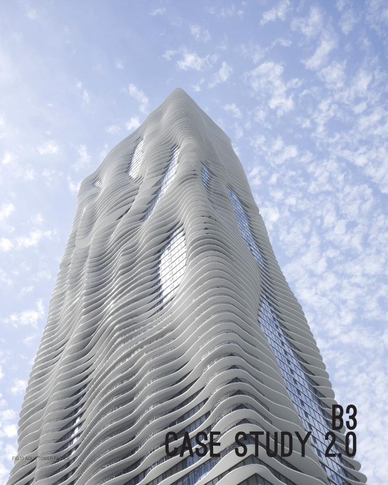
FIG.11 AQUA TOWER FACADE

CRITERIA DESIGN 37
Studio Gangaqua towerFor Case study 2.0 we were required to use or newly acquired grasshopper skills to reverse engineer a project relevant to the field of parametric patterning. I Selected Studio Gang’s Aqua Tower because, unlike the De Young Museum, it allowed me to work with three dimensional forms.
The tower is otherwise conventional massing is wrapped in a series of unique curving concrete balconies whose combined visual effect gives the impression of a gently undulating surface. This effect has been compared to
windblown water or fabric, the low pools and ridges of a tidal flat or striations in weathered sandstone. The actual drivers behind their generation however where performative and experiential. The balconies dissipate both solar and wind loads, reducing the need for artificial cooling and structural reinforcement. 3.1 Furthermore, they frame views and by breaking wind allow balconies at greater heights than would usually be practical, redefining the relationship of inhabitants with the outdoors.3.2
38 CRITERIA DESIGN
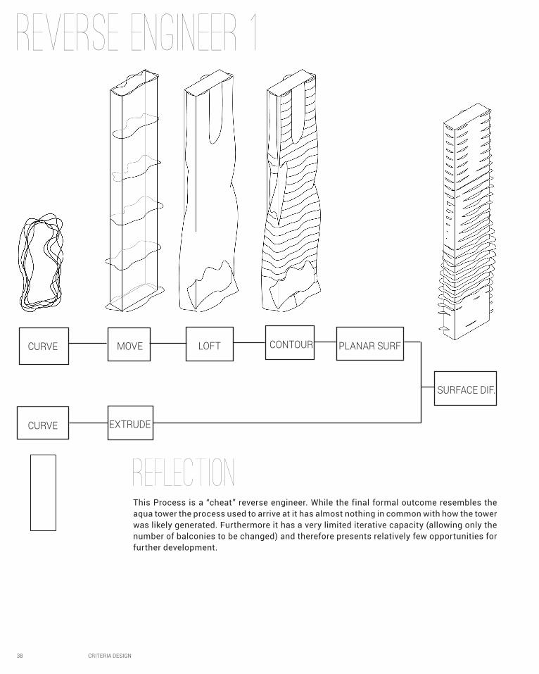
REverse engineer 1
CURVE MOVE LOFT CONTOUR PLANAR SURF
SURFACE DIF.
EXTRUDECURVE
This Process is a “cheat” reverse engineer. While the final formal outcome resembles the aqua tower the process used to arrive at it has almost nothing in common with how the tower was likely generated. Furthermore it has a very limited iterative capacity (allowing only the number of balconies to be changed) and therefore presents relatively few opportunities for further development.
REFLECTION
CRITERIA DESIGN 39
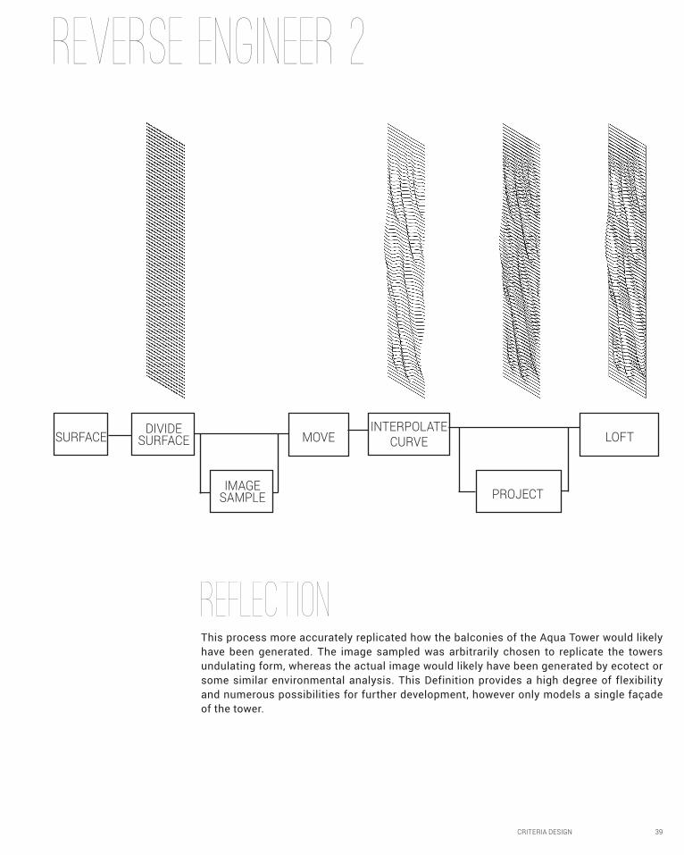
REverse engineer 2
SURFACE DIVIDE SURFACE
IMAGE SAMPLE
MOVEINTERPOLATE
CURVE
PROJECT
LOFT
This process more accurately replicated how the balconies of the Aqua Tower would likely have been generated. The image sampled was arbitrarily chosen to replicate the towers undulating form, whereas the actual image would likely have been generated by ecotect or some similar environmental analysis. This Definition provides a high degree of flexibility and numerous possibilities for further development, however only models a single façade of the tower.
REFLECTION
40 CRITERIA DESIGN
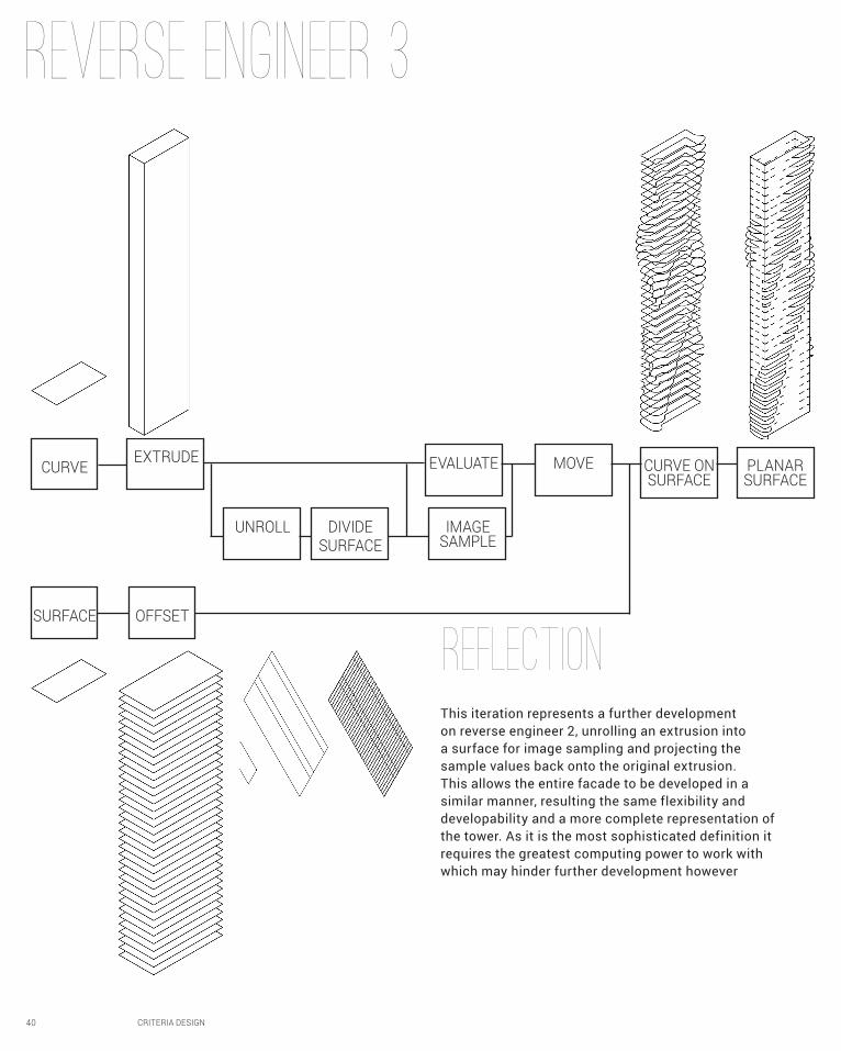
Reverse engineer 3
This iteration represents a further development on reverse engineer 2, unrolling an extrusion into a surface for image sampling and projecting the sample values back onto the original extrusion. This allows the entire facade to be developed in a similar manner, resulting the same flexibility and developability and a more complete representation of the tower. As it is the most sophisticated definition it requires the greatest computing power to work with which may hinder further development however
REFLECTION
CURVE
SURFACE OFFSET
EXTRUDE
UNROLL DIVIDESURFACE
EVALUATE MOVE CURVE ON SURFACE
PLANAR SURFACE
IMAGE SAMPLE
CRITERIA DESIGN 41
42 CRITERIA DESIGN
B4Technique Development
CRITERIA DESIGN 43
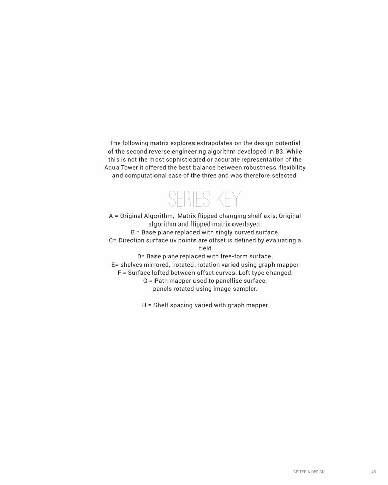
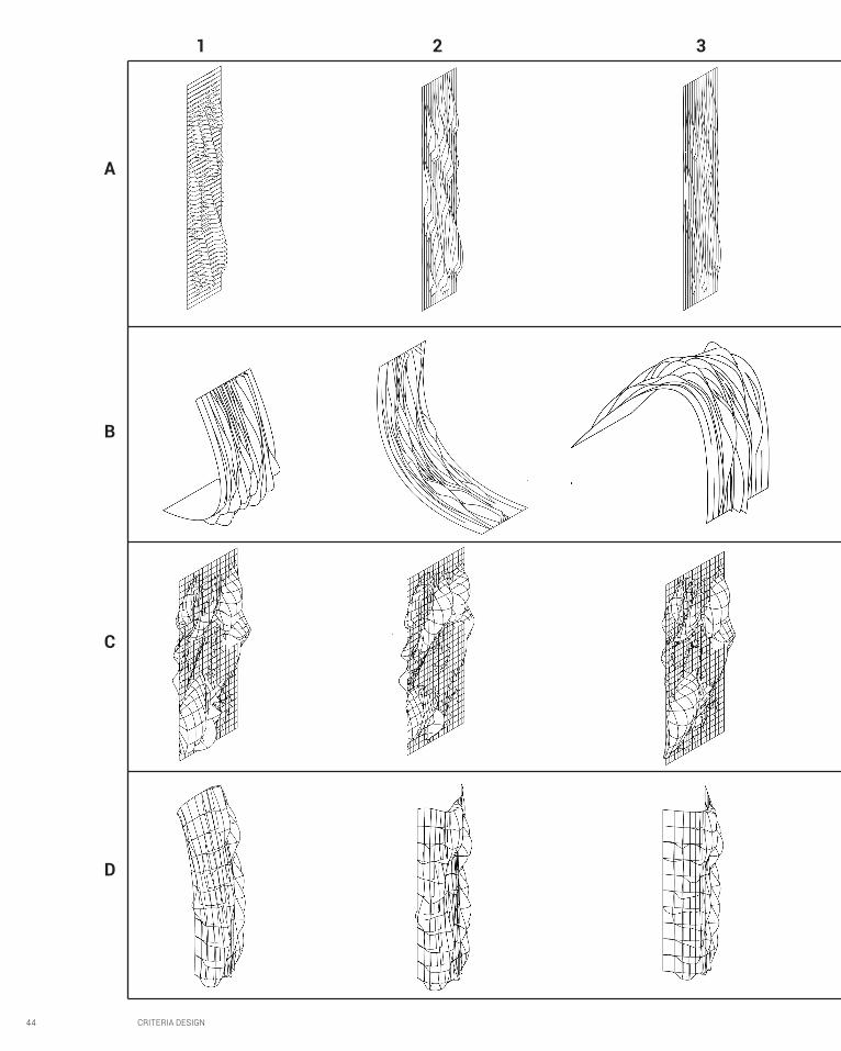
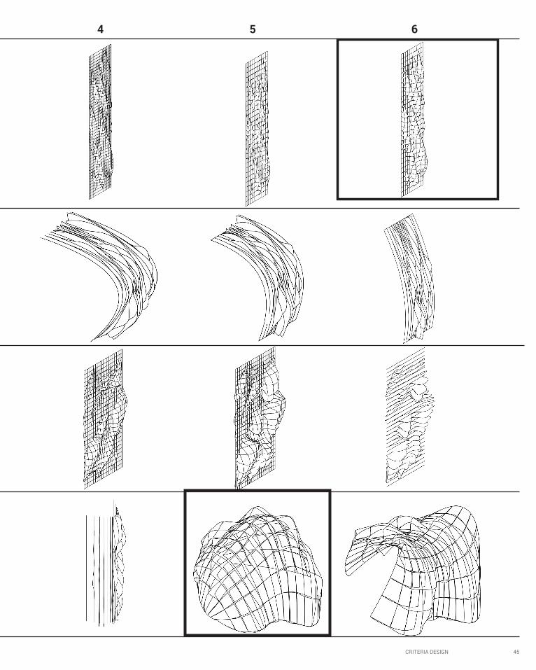
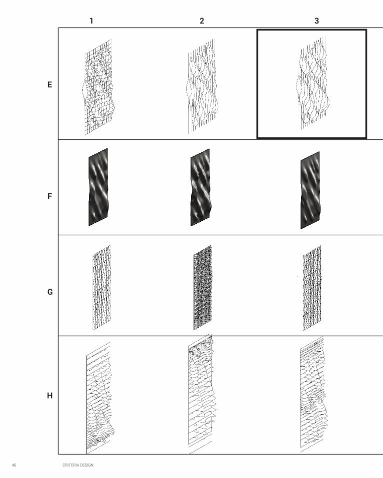
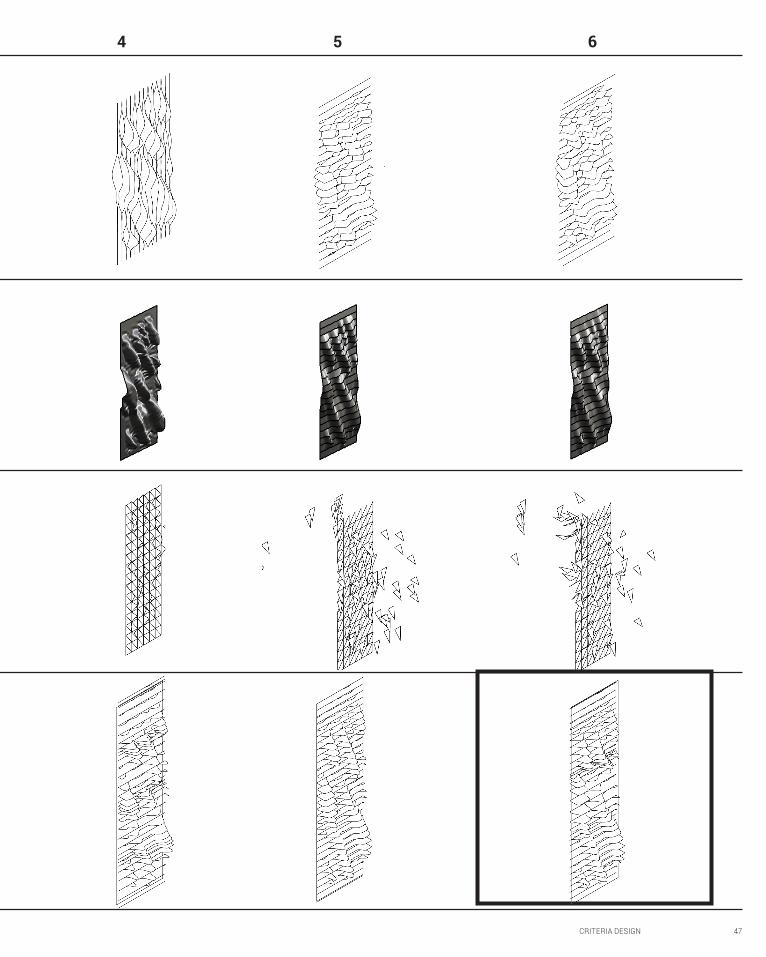
The following matrix explores extrapolates on the design potential of the second reverse engineering algorithm developed in B3. While this is not the most sophisticated or accurate representation of the
Aqua Tower it offered the best balance between robustness, flexibility and computational ease of the three and was therefore selected.
SERIES KEYA = Original Algorithm, Matrix flipped changing shelf axis, Original
algorithm and flipped matrix overlayed. B = Base plane replaced with singly curved surface.
C= Direction surface uv points are offset is defined by evaluating a field
D= Base plane replaced with free-form surface. E= shelves mirrored, rotated, rotation varied using graph mapper
F = Surface lofted between offset curves. Loft type changed. G = Path mapper used to panellise surface,
panels rotated using image sampler.
H = Shelf spacing varied with graph mapper
44 CRITERIA DESIGN
A
B
C
D
1 2 3
CRITERIA DESIGN 45
4 5 6
46 CRITERIA DESIGN
E
F
G
H
1 2 3
CRITERIA DESIGN 47
4 5 6

48 CRITERIA DESIGN
Selection Criteria
To be considered successful species needed to be plausibly developable, this meant that doubly curved surfaces, intersecting geometry and significant cantilevers where avoided where possible.
Four species which passed this Initial test where selected as the basis for further design speculation. As my design proposal is currently conceptually underdeveloped this selection process was not based on how these proposals fulfilled a specific
set of design criteria. Rather they where taken as potential starting points for a design, and a group of species which suggested the greatest diversity of overall design directions were selected. This process therefore employs parametric software to generate numerous iterations rapidly in a more explorative manner, rather than to refine a preconceived design in regards to certain criteria.
ITERATION E3ITERATION G6
The variation in shelf spacing in this iteration suggests the possibility of embedding site data in a design by varying this parameter, this may include the exclusion of undesirable views or adapting shading to lighting patterns. Alternatively this could be a response to each shelf supporting different plants, objects, or habitation patterns.
These vertical elements could possibly become adaptive shading elements, rotating in their vertical axis in response to solar loads. This would also result in complex dappled patterns of light and shadow. It could also be developed from lightweight elements suspended between ropes which would rotate in the wind, creating rippling shadow effects
CRITERIA DESIGN 49
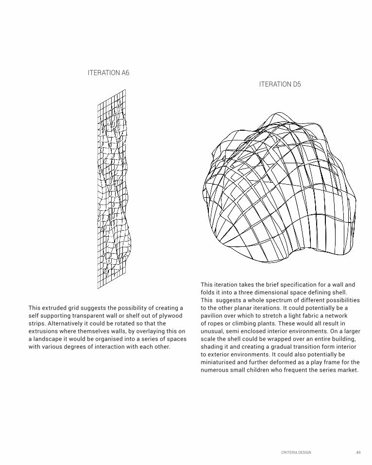
ITERATION D5
This extruded grid suggests the possibility of creating a self supporting transparent wall or shelf out of plywood strips. Alternatively it could be rotated so that the extrusions where themselves walls, by overlaying this on a landscape it would be organised into a series of spaces with various degrees of interaction with each other.
This iteration takes the brief specification for a wall and folds it into a three dimensional space defining shell. This suggests a whole spectrum of different possibilities to the other planar iterations. It could potentially be a pavilion over which to stretch a light fabric a network of ropes or climbing plants. These would all result in unusual, semi enclosed interior environments. On a larger scale the shell could be wrapped over an entire building, shading it and creating a gradual transition form interior to exterior environments. It could also potentially be miniaturised and further deformed as a play frame for the numerous small children who frequent the series market.
ITERATION A6

50 CRITERIA DESIGN
B5Prototyping
CRITERIA DESIGN 51
Having considered the possible techniques suggested by the outcomes of B5 in relation to
my CERES I began to formulate a design proposal conceptually. I hope to create a series of parametric
planters based on iteration G6. These would span between the pre-exiting columns supporting the northern veranda of the Merri Table Café.
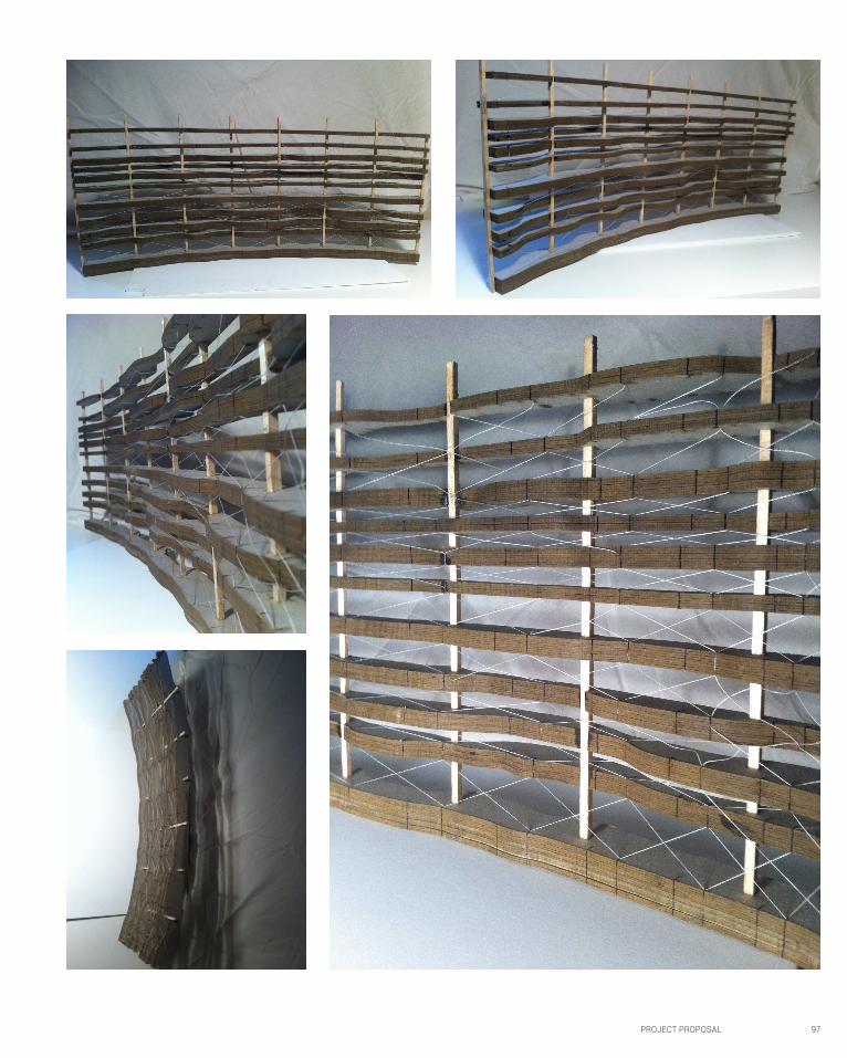
In order to create a physical study model I was therefore required to measure the size and spacing
of the columns on site, model them digitally in rhino, reference this into grasshopper and subtract
the columns form the parametrically generated form. This created correctly spaced holes when the geometry was laid out for fabrication through which to fit balsa wood columns when creating the model.
This model could be used to test the spatial qualities created by turning the
veranda into a semi enclosed area.
52 CRITERIA DESIGN
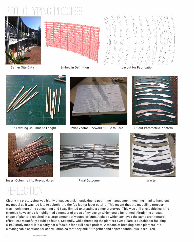
PROtotyping proCESS.
REFLECTION
Print Vector Linework & Glue to Card Cut out Parametric Planters
Insert Columns into Precut Holes Final Outcome Waste
Cut Existing Columns to Length
Gather Site Data Embed in Definition Layout for Fabrication
Clearly my prototyping was highly unsuccessful, mostly due to poor time management meaning I had to hand cut my model as it was too late to submit it to the fab lab for laser cutting. This meant that the modelling process was much more time consuming and I was limited to creating a singe prototype. This was still a valuable learning exercise however as it highlighted a number of areas of my design which could be refined. Firstly the unusual shape of planters resulted in a large amount of wasted offcuts. A shape which achieves the same architectural effect less wastefully could be found. Secondly, while threading the planters over pillars is suitable for building a 1:50 study model it is clearly not a feasible for a full scale project. A means of breaking down planters into a manageable sections for construction so that they still fit together and appear continuous is required.
2M
6M
CRITERIA DESIGN 53
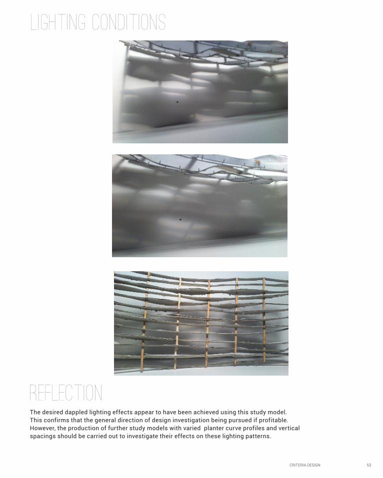
LIGHTING CONDITIONS
REFLECTIONThe desired dappled lighting effects appear to have been achieved using this study model. This confirms that the general direction of design investigation being pursued if profitable. However, the production of further study models with varied planter curve profiles and vertical spacings should be carried out to investigate their effects on these lighting patterns.

54 CRITERIA DESIGN
B6PROPOSAL
CRITERIA DESIGN 55
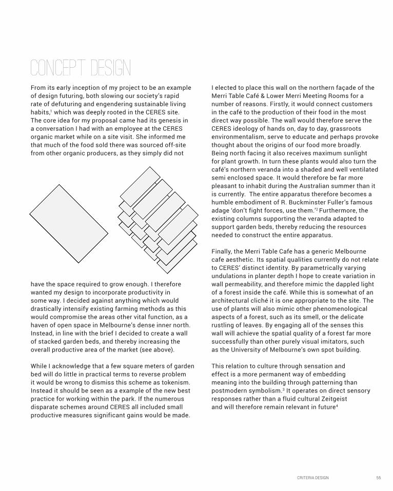
CONCEPT DESIGNFrom its early inception of my project to be an example of design futuring, both slowing our society’s rapid rate of defuturing and engendering sustainable living habits,1 which was deeply rooted in the CERES site. The core idea for my proposal came had its genesis in a conversation I had with an employee at the CERES organic market while on a site visit. She informed me that much of the food sold there was sourced off-site from other organic producers, as they simply did not
have the space required to grow enough. I therefore wanted my design to incorporate productivity in some way. I decided against anything which would drastically intensify existing farming methods as this would compromise the areas other vital function, as a haven of open space in Melbourne’s dense inner north. Instead, in line with the brief I decided to create a wall of stacked garden beds, and thereby increasing the overall productive area of the market (see above).
While I acknowledge that a few square meters of garden bed will do little in practical terms to reverse problem it would be wrong to dismiss this scheme as tokenism. Instead it should be seen as a example of the new best practice for working within the park. If the numerous disparate schemes around CERES all included small productive measures significant gains would be made.
I elected to place this wall on the northern façade of the Merri Table Café & Lower Merri Meeting Rooms for a number of reasons. Firstly, it would connect customers in the café to the production of their food in the most direct way possible. The wall would therefore serve the CERES ideology of hands on, day to day, grassroots environmentalism, serve to educate and perhaps provoke thought about the origins of our food more broadly. Being north facing it also receives maximum sunlight for plant growth. In turn these plants would also turn the café’s northern veranda into a shaded and well ventilated semi enclosed space. It would therefore be far more pleasant to inhabit during the Australian summer than it is currently. The entire apparatus therefore becomes a humble embodiment of R. Buckminster Fuller’s famous adage ‘don’t fight forces, use them.’2 Furthermore, the existing columns supporting the veranda adapted to support garden beds, thereby reducing the resources needed to construct the entire apparatus.
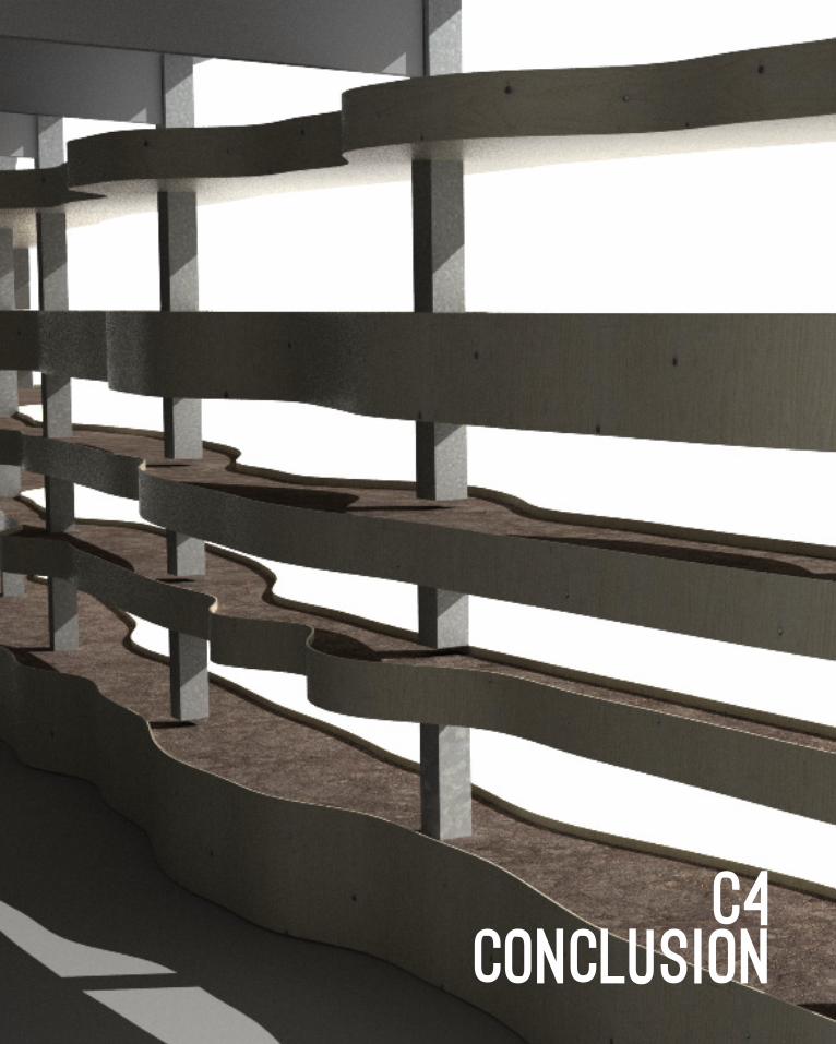
Finally, the Merri Table Cafe has a generic Melbourne cafe aesthetic. Its spatial qualities currently do not relate to CERES’ distinct identity. By parametrically varying undulations in planter depth I hope to create variation in wall permeability, and therefore mimic the dappled light of a forest inside the café. While this is somewhat of an architectural cliché it is one appropriate to the site. The use of plants will also mimic other phenomenological aspects of a forest, such as its smell, or the delicate rustling of leaves. By engaging all of the senses this wall will achieve the spatial quality of a forest far more successfully than other purely visual imitators, such as the University of Melbourne’s own spot building.
This relation to culture through sensation and effect is a more permanent way of embedding meaning into the building through patterning than postmodern symbolism.3 It operates on direct sensory responses rather than a fluid cultural Zeitgeist and will therefore remain relevant in future4
56 CRITERIA DESIGN
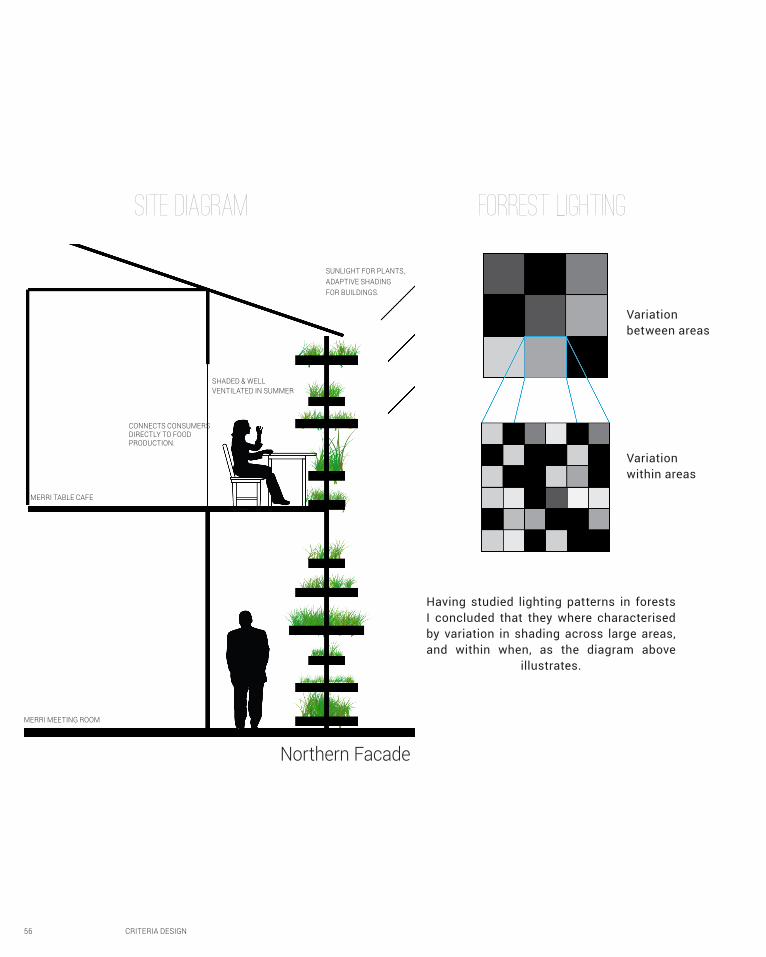
Northern Facade
SUNLIGHT FOR PLANTS, ADAPTIVE SHADING FOR BUILDINGS.
SHADED & WELL VENTILATED IN SUMMER
CONNECTS CONSUMERS DIRECTLY TO FOOD PRODUCTION.
MERRI TABLE CAFE
MERRI MEETING ROOM
Forrest LightingSite Diagram
Variation between areas
Variation within areas
Having studied lighting patterns in forests I concluded that they where characterised by variation in shading across large areas, and within when, as the diagram above
illustrates.
CRITERIA DESIGN 57
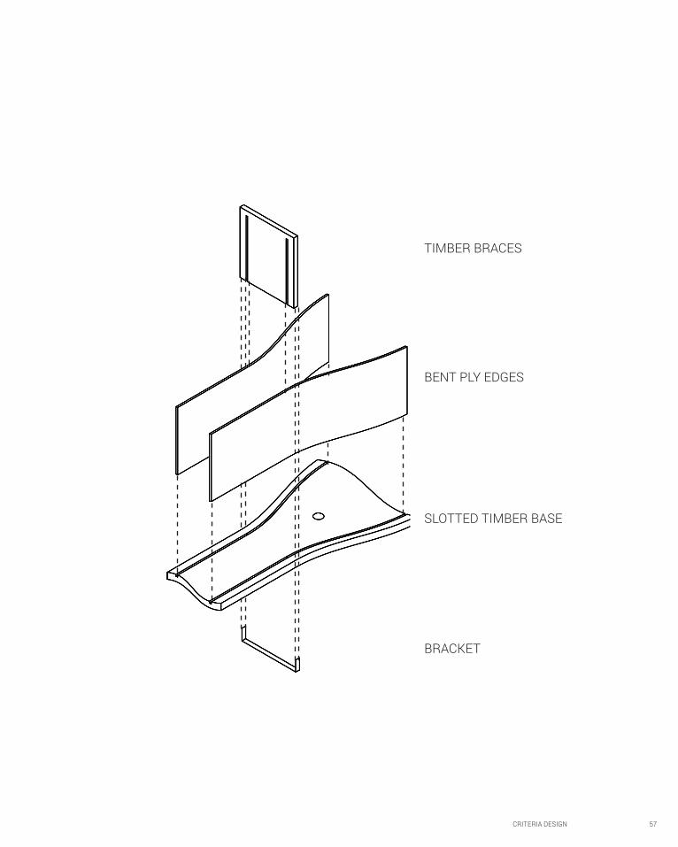
BENT PLY EDGES
TIMBER BRACES
BRACKET
SLOTTED TIMBER BASE
58 CRITERIA DESIGN
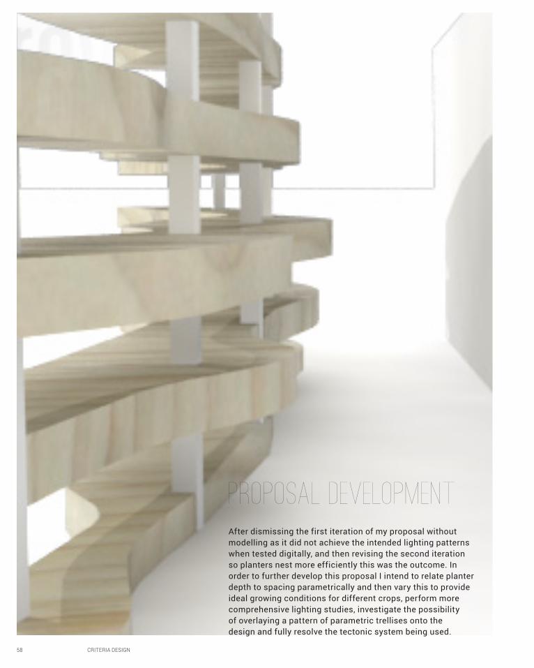
After dismissing the first iteration of my proposal without modelling as it did not achieve the intended lighting patterns when tested digitally, and then revising the second iteration so planters nest more efficiently this was the outcome. In order to further develop this proposal I intend to relate planter depth to spacing parametrically and then vary this to provide ideal growing conditions for different crops, perform more comprehensive lighting studies, investigate the possibility of overlaying a pattern of parametric trellises onto the design and fully resolve the tectonic system being used.
Proposal development
CRITERIA DESIGN 59

60 CRITERIA DESIGN
B7LEARNING OUTCOMES

CRITERIA DESIGN 61
Working on my proposal up until this point has helped me develop my parametric design skills. My project involved image sampling with points projected onto unrolled surfaces creating unusual and
impractical data structures. As issues occur frequently I have been forced to resolve them myself without specific technical help. This has forced me to further my understanding of data structures and how to manipulate them into more amenable forms, a fundamental
skill for designing parametrically. Furthermore I am now able to critique design options suggested by a parametric model more
rigorously and empirically, especially in terms of their developability.
Reverse engineering Studio Gang’s aqua tower also forced me to analyse complex built form in a new way, deducing the different methods which it may have been computationally
generated, their relative advantages and disadvantages, and the architectural intent behind decisions.
While I feel my ability to construct a persuasive design proposal has not been stretched beyond what I had already developed in previous studios, exposure to contemporary design theory
in both parts A and B has given me a greater wealth of material on which to base arguments. I have not, as yet, developed any
digital fabrication skills as intended in B5 as previously outlined. There will be further opportunities do so in part C however.
62 CRITERIA DESIGN
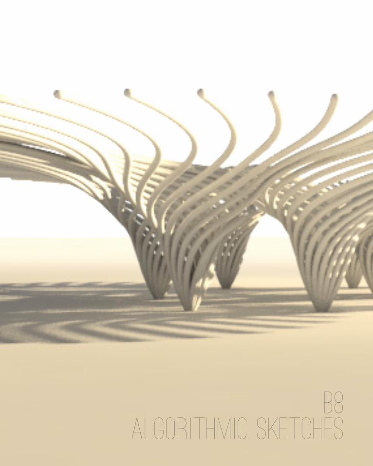
B8ALGORITHMIC SKETCHES

CRITERIA DESIGN 63
64 CRITERIA DESIGN
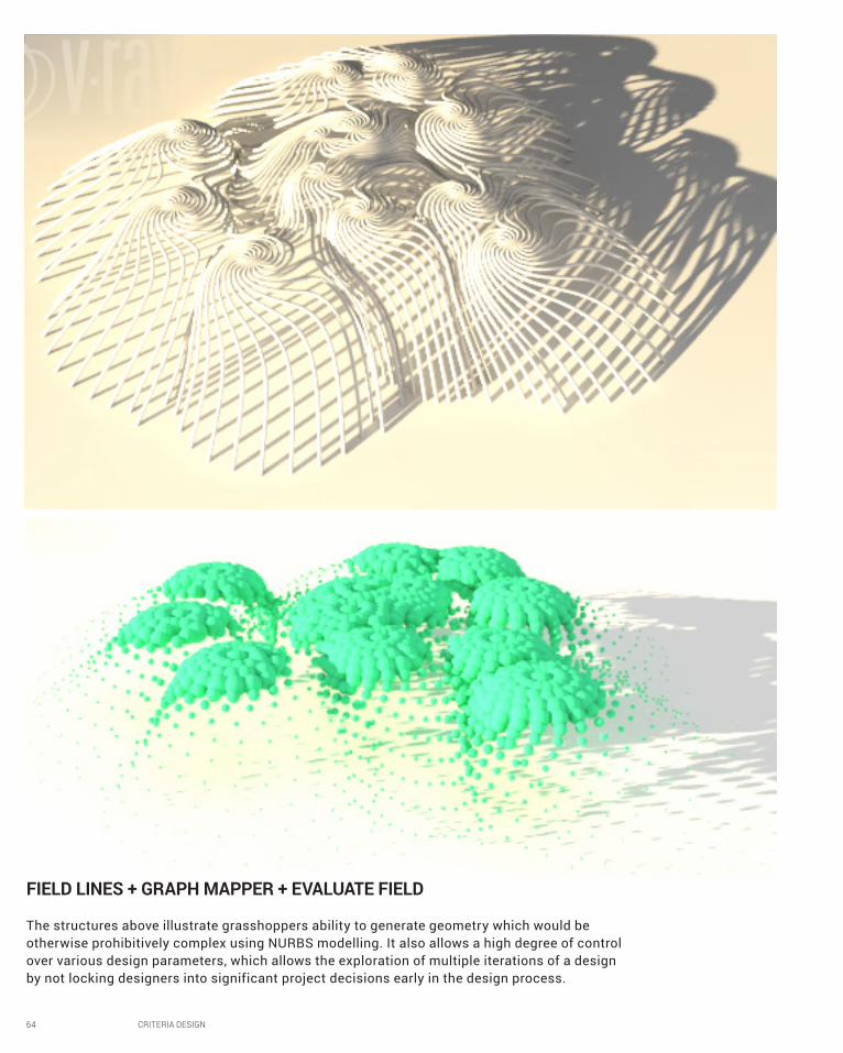
FIELD LINES + GRAPH MAPPER + EVALUATE FIELD
The structures above illustrate grasshoppers ability to generate geometry which would be otherwise prohibitively complex using NURBS modelling. It also allows a high degree of control over various design parameters, which allows the exploration of multiple iterations of a design by not locking designers into significant project decisions early in the design process.
CRITERIA DESIGN 65
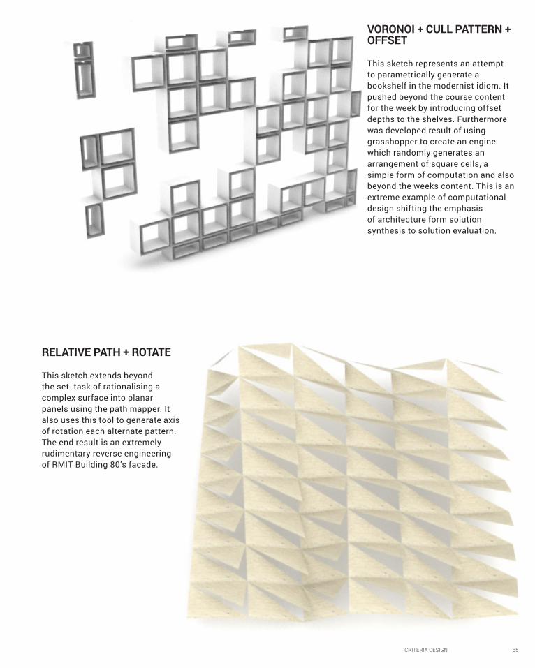
VORONOI + CULL PATTERN + OFFSET
This sketch represents an attempt to parametrically generate a bookshelf in the modernist idiom. It pushed beyond the course content for the week by introducing offset depths to the shelves. Furthermore was developed result of using grasshopper to create an engine which randomly generates an arrangement of square cells, a simple form of computation and also beyond the weeks content. This is an extreme example of computational design shifting the emphasis of architecture form solution synthesis to solution evaluation.
RELATIVE PATH + ROTATE
This sketch extends beyond the set task of rationalising a complex surface into planar panels using the path mapper. It also uses this tool to generate axis of rotation each alternate pattern. The end result is an extremely rudimentary reverse engineering of RMIT Building 80’s facade.
66 CRITERIA DESIGN
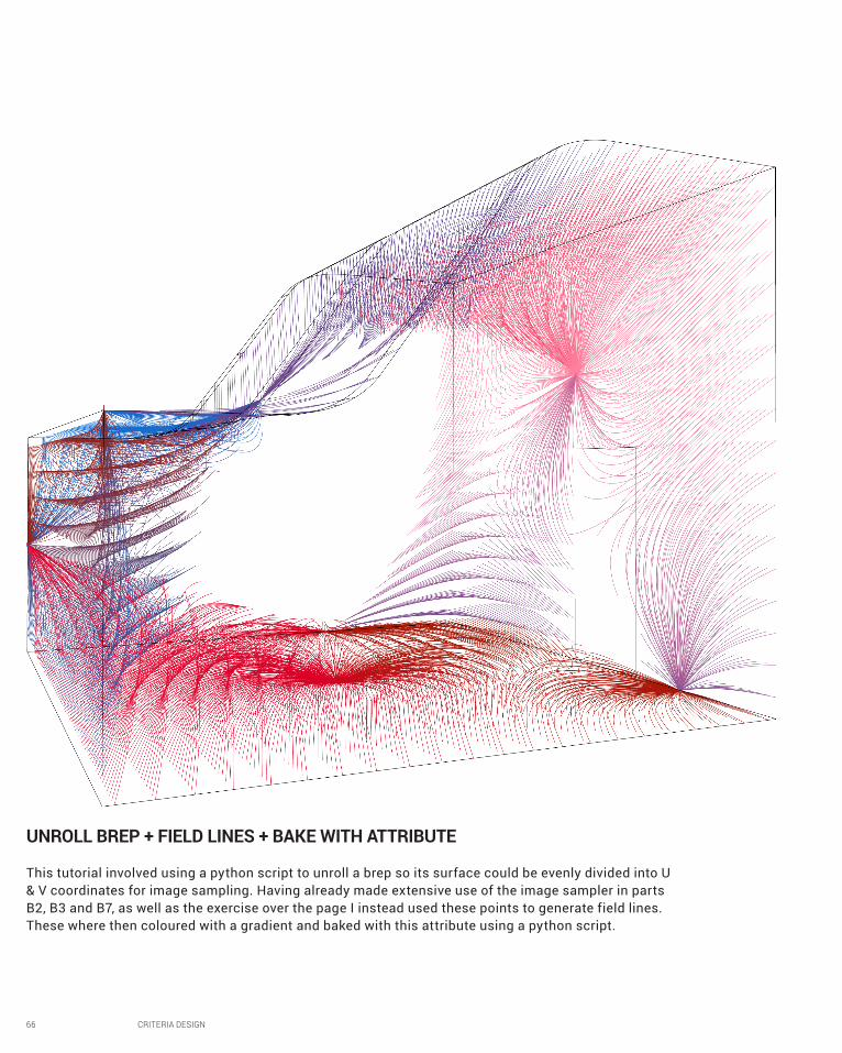
UNROLL BREP + FIELD LINES + BAKE WITH ATTRIBUTE
This tutorial involved using a python script to unroll a brep so its surface could be evenly divided into U & V coordinates for image sampling. Having already made extensive use of the image sampler in parts B2, B3 and B7, as well as the exercise over the page I instead used these points to generate field lines. These where then coloured with a gradient and baked with this attribute using a python script.
CRITERIA DESIGN 67
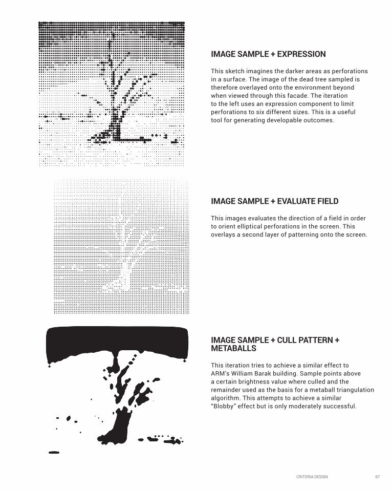
IMAGE SAMPLE + EXPRESSION
This sketch imagines the darker areas as perforations in a surface. The image of the dead tree sampled is therefore overlayed onto the environment beyond when viewed through this facade. The iteration to the left uses an expression component to limit perforations to six different sizes. This is a useful tool for generating developable outcomes.
IMAGE SAMPLE + EVALUATE FIELD
This images evaluates the direction of a field in order to orient elliptical perforations in the screen. This overlays a second layer of patterning onto the screen.
IMAGE SAMPLE + CULL PATTERN + METABALLS
This iteration tries to achieve a similar effect to ARM’s William Barak building. Sample points above a certain brightness value where culled and the remainder used as the basis for a metaball triangulation algorithm. This attempts to achieve a similar “Blobby” effect but is only moderately successful.

68 CRITERIA DESIGN
FIGURESFigure 9: Sheng Zhonghai, AU Offices and Exhibition Space Facade, 2010, Photograph <http://www.archdaily.com/82251/au-office-and-exhibition-space-archi-union-architects-inc/> [Accessed 28 April 2016]
Figure 10: Lauren Golightly, De Young Museum Facade, 2014, Photograph < http://theglobalgrid.org/san-franciscos-de-young-museum-smart-or-not/> [accessed 1 April 2016]
Figure 11: Hendrich Blessing, Aqua Tower, 2010, Photograph < http://www.archdaily.com/42694/aqua-tower-studio-gang-architects> [Accessed 6 April 2016]
CRITERIA DESIGN 69
1.1 Mark Garcia, ‘Prologue for the History, Theory and Future of patterns in Architecture and Spatial Design’, Architectural Design, 79.6 (November 2009), 6-17.
1.2 Ibid.
1.3 Patrick Schumacher, ‘Parametric Patterns’, Architectural Design, 79.6 (November 2009), 28-41.
1.4 Julian Vincent, ‘Biomimetic Patterns in Architectural Design’, Architectural Design, 79.6 (November 2009), 74-81.
1.5 Patricia Roderman, ‘Psychology an Perception of Patterns in Architecture’, Architectural Design, 79.6 (November 2009, 100-107.
1.6 Kengo Kuma, in Garcia, 6-17.
2.1 Adalyn Perez, “de Young Museum / Herzog & de Meuron” in Archdaily < http://www.archdaily.com/66619/m-h-de-young-museum-herzog-de-meuron>
2.2 Brady Peters, ‘Realising the Architectural Intent: Computation at Herzog & De Meuron’, Architectural Design, 83.2 (March 2013), 56-61.
2.3Ibid.
3.1 Paul Goldberger, ‘wave effect’, New Yorker, 1 February 2010, < http://www.newyorker.com/magazine/2010/02/01/wave-effect>
3.2 Ibid.
6.1 Design Futuring: Sustainability, Ethics and New Practice, ed. by Tony Fry, (Oxford: Berg, 2009) pp. 1-16.
6.2 R. Buckminster Fuller, “Doing the Most with the Least”, Shelter 4 (1932).
6.3 The Function of Ornament, eds. Farshid Moussavi and Micheal Kubo, (Barcelona: Actar, 2006) pp.5-14.
6.4 Ibid.
REFERENCES

70 PROJECT PROPOSAL
PART CDEtailed design

PROJECT PROPOSAL 71
C1Design ConCEPT
72 PROJECT PROPOSAL
Planter Depth & Spacing
PROJECT PROPOSAL 73
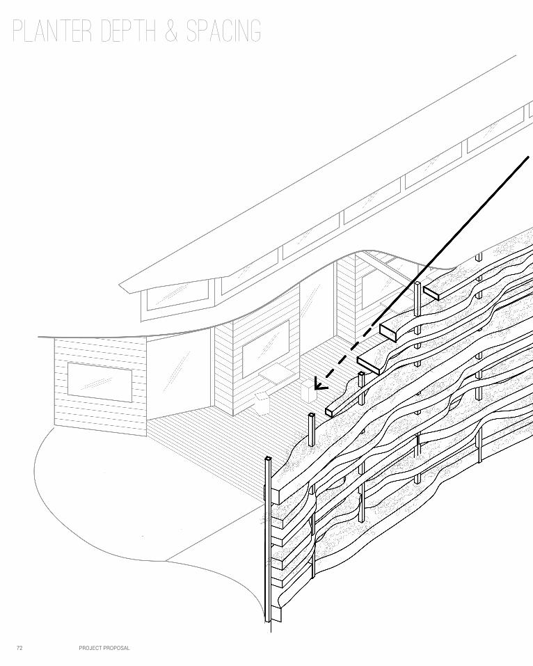
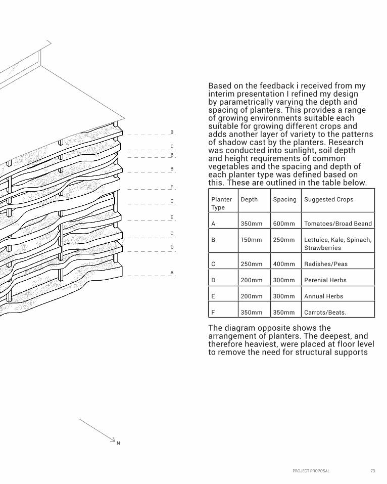
Based on the feedback i received from my interim presentation I refined my design by parametrically varying the depth and spacing of planters. This provides a range of growing environments suitable each suitable for growing different crops and adds another layer of variety to the patterns of shadow cast by the planters. Research was conducted into sunlight, soil depth and height requirements of common vegetables and the spacing and depth of each planter type was defined based on this. These are outlined in the table below.
Planter Type
Depth Spacing Suggested Crops
A 350mm 600mm Tomatoes/Broad Beand
B 150mm 250mm Lettuice, Kale, Spinach, Strawberries
C 250mm 400mm Radishes/Peas
D 200mm 300mm Perenial Herbs
E 200mm 300mm Annual Herbs
F 350mm 350mm Carrots/Beats.
The diagram opposite shows the arrangement of planters. The deepest, and therefore heaviest, were placed at floor level to remove the need for structural supports
A
N
D
C
C
E
F
B
B
C
B
74 PROJECT PROPOSAL
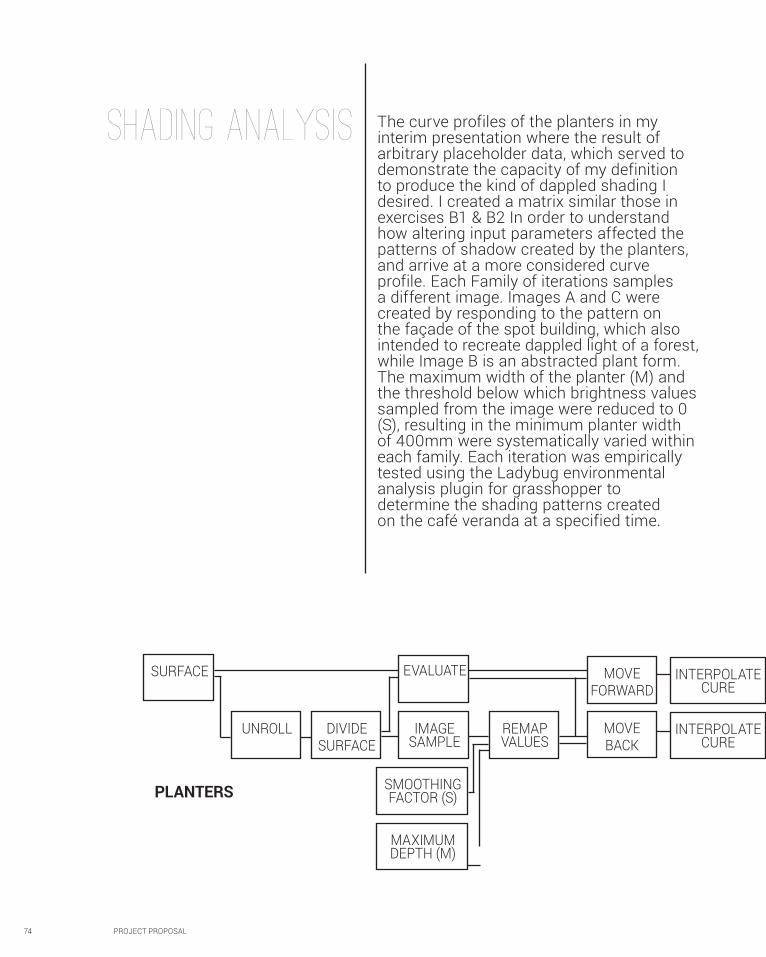
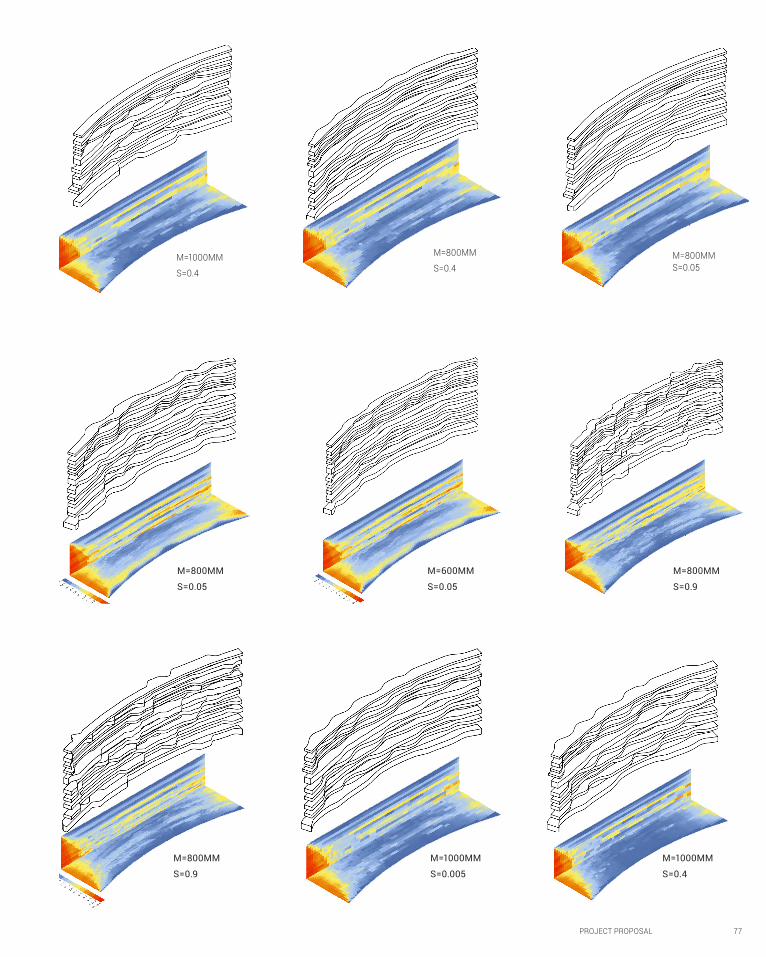
SHADING ANALYSIS The curve profiles of the planters in my interim presentation where the result of arbitrary placeholder data, which served to demonstrate the capacity of my definition to produce the kind of dappled shading I desired. I created a matrix similar those in exercises B1 & B2 In order to understand how altering input parameters affected the patterns of shadow created by the planters, and arrive at a more considered curve profile. Each Family of iterations samples a different image. Images A and C were created by responding to the pattern on the façade of the spot building, which also intended to recreate dappled light of a forest, while Image B is an abstracted plant form. The maximum width of the planter (M) and the threshold below which brightness values sampled from the image were reduced to 0 (S), resulting in the minimum planter width of 400mm were systematically varied within each family. Each iteration was empirically tested using the Ladybug environmental analysis plugin for grasshopper to determine the shading patterns created on the café veranda at a specified time.
UNROLL DIVIDESURFACE
EVALUATE MOVEFORWARD
MOVEBACK
INTERPOLATE CURE
INTERPOLATE CURE
IMAGE SAMPLE
SMOOTHING FACTOR (S)
MAXIMUM DEPTH (M)
REMAP VALUES
SURFACE
PLANTERS
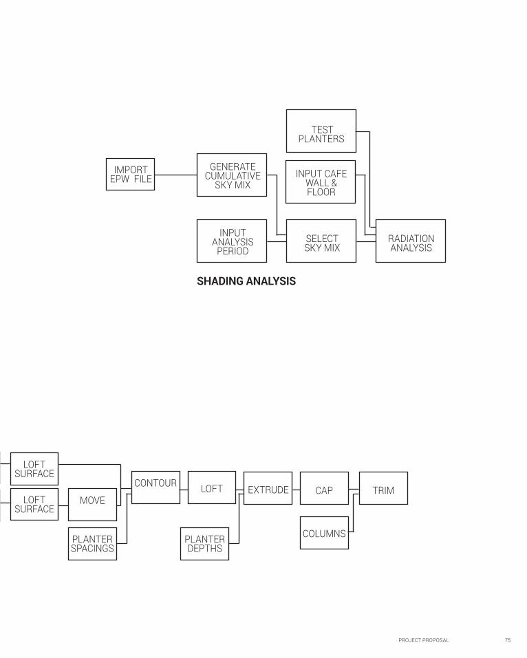
PROJECT PROPOSAL 75
IMPORT EPW FILE
GENERATE CUMULATIVE
SKY MIX
SELECT SKY MIX
RADIATION ANALYSIS
INPUT CAFE WALL & FLOOR
TEST PLANTERS
INPUT ANALYSIS
PERIOD
EXTRUDE CAP
COLUMNS
TRIMLOFTMOVE
CONTOUR
PLANTER SPACINGS
PLANTER DEPTHS
LOFT SURFACE
LOFT SURFACE
SHADING ANALYSIS
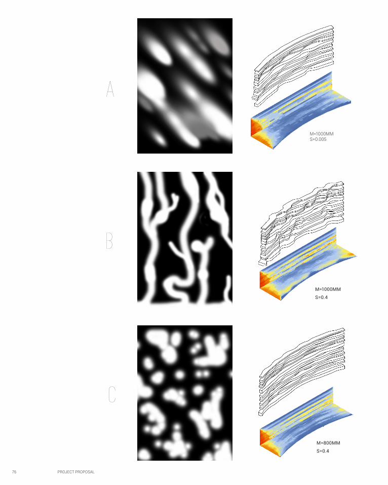
76 PROJECT PROPOSAL
M=1000MM S=0.005
M=1000MM
S=0.4
M=800MM
S=0.4
B
A
c
PROJECT PROPOSAL 77
M=1000MM
S=0.4
M=1000MM
S=0.005
M=800MM
S=0.9
M=1000MM
S=0.4
M=800MM
S=0.4
M=800MM
S=0.05
M=800MM S=0.05
M=800MM
S=0.9
M=600MM
S=0.05
78 PROJECT PROPOSAL
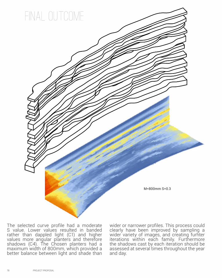
FINAL OUTCOME
M=800mm S=0.3
The selected curve profile had a moderate S value. Lower values resulted in banded rather than dappled light (C1) and higher values more angular planters and therefore shadows (C4). The Chosen planters had a maximum width of 800mm, which provided a better balance between light and shade than
wider or narrower profiles. This process could clearly have been improved by sampling a wider variety of images, and creating furhter iterations within each family. Furthermore the shadows cast by each iteration should be assessed at several times throughout the year and day.
PROJECT PROPOSAL 79
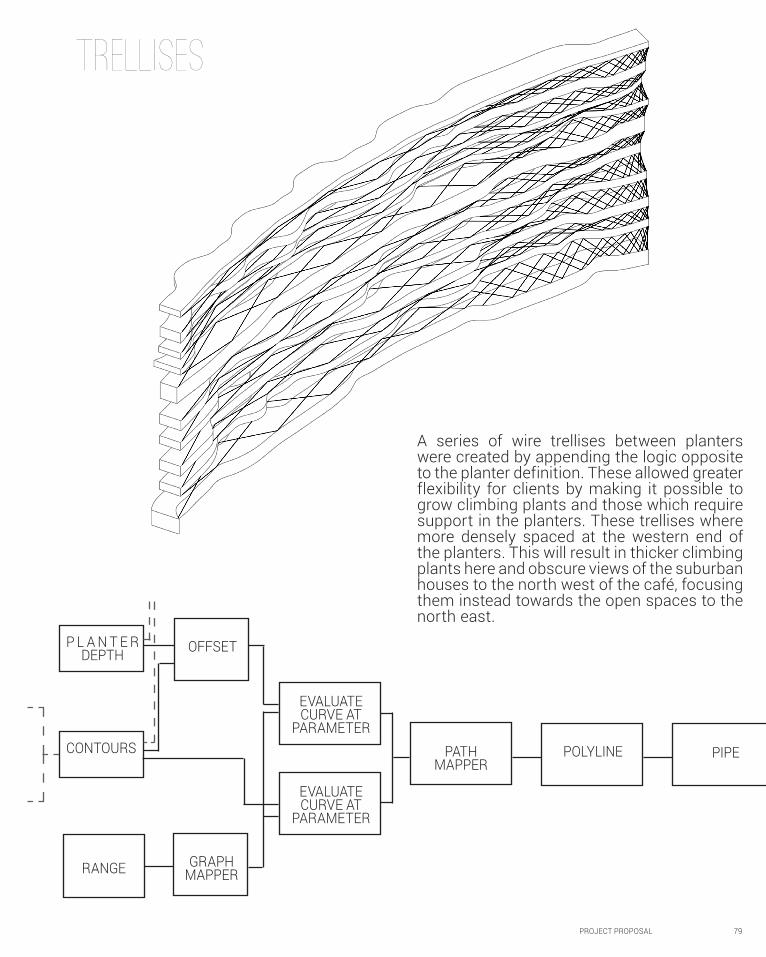
TRELLISES
CONTOURS
P L A N T E R DEPTH
EVALUATE CURVE AT
PARAMETER
EVALUATE CURVE AT
PARAMETER
GRAPH MAPPER
OFFSET
POLYLINEPATH MAPPER
PIPE
RANGE
A series of wire trellises between planters were created by appending the logic opposite to the planter definition. These allowed greater flexibility for clients by making it possible to grow climbing plants and those which require support in the planters. These trellises where more densely spaced at the western end of the planters. This will result in thicker climbing plants here and obscure views of the suburban houses to the north west of the café, focusing them instead towards the open spaces to the north east.

80 PROJECT PROPOSAL
C2TECTONIC DETAIL
PROJECT PROPOSAL 81
As CERES is a community organisation with extremely limited funds I wanted
my proposal to be built with off the shelf components and unskilled volunteer
labour wherever possible. Therefore the only custom fabricated component of the whole tectonic system is the timber top
and bottom plates for the planters, which must be CNC routed. Stage one is the only step of the process which requires skilled
tradespeople for welding, after this the remaining five steps can be carried out by CERES volunteers using basic power tools.
82 PROJECT PROPOSAL
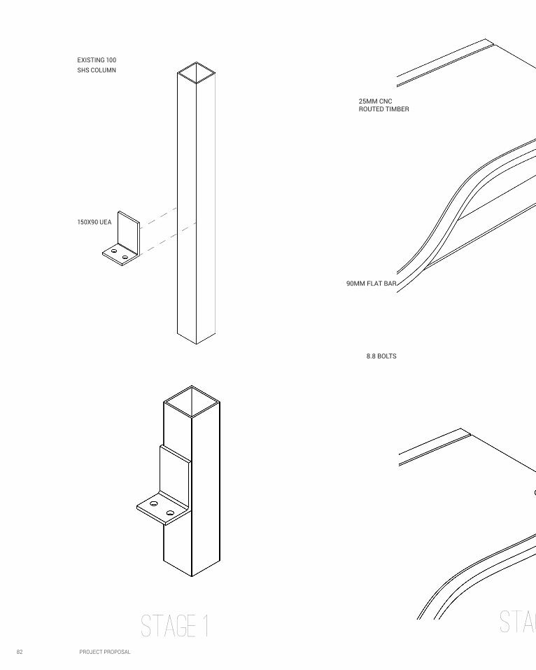
STAGE 1
EXISTING 100 SHS COLUMN
150X90 UEA
STAGE 2
8.8 BOLTS
90MM FLAT BAR
25MM CNC ROUTED TIMBER
PROJECT PROPOSAL 83
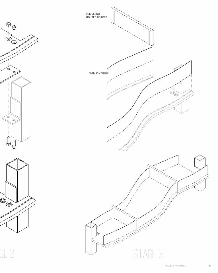
STAGE 2
3MM PLY STRIP
25MM CNC ROUTED BRACES
STAGE 3
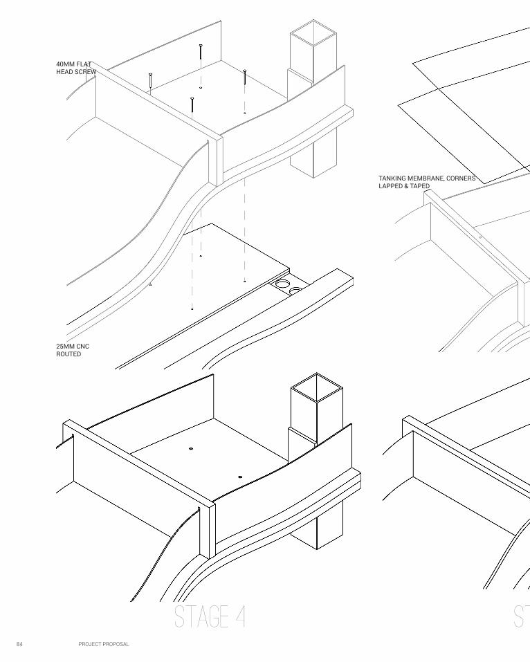
84 PROJECT PROPOSAL
STAGE 4
25MM CNC ROUTED
40MM FLAT HEAD SCREW
TANKING MEMBRANE, CORNERS LAPPED & TAPED
STAGE 5
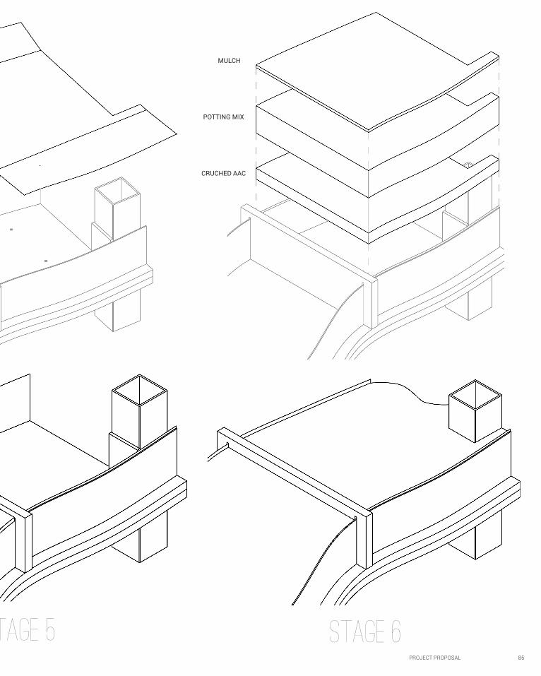
PROJECT PROPOSAL 85
STAGE 6
MULCH
POTTING MIX
CRUCHED AAC
STAGE 5
86 PROJECT PROPOSAL
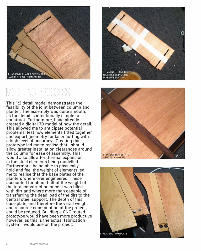
1 - ASSEMBLE LASER CUT TIMBER LAYERS OF EACH COMPONENT
2 - LAMINATE COMPONENTS TOGETHER USING GLUE , TAPE WHILE DRYING.
8 -PLACE BOTTOM PLATE
5 - INSERT BRACES INTO GROOVES AND GLUE
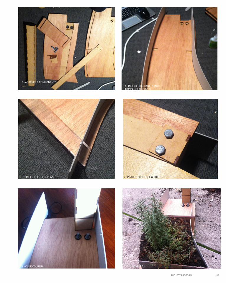
This 1:2 detail model demonstrates the feasibility of the joint between column and planter. The assembly was quite smooth, as the detail is intentionally simple to construct. Furthermore, I had already created a digital 3D model of how the detail. This allowed me to anticipate potential problems, test how elements fitted together and export geometry for laser cutting with a high level of accuracy. Creating this prototype led me to realise that I should allow greater installation clearances around the column for ease of assembly. This would also allow for thermal expansion in the steel elements being modelled. Furthermore, being able to physically hold and feel the weight of elements led me to realise that the base plates of the planters where over engineered. These accounted for about half of the weight of the total construction once it was filled with dirt and where more than capable of transferring the dead load of the dirt to the central steel support. The depth of this base plate, and therefore the verall weight and resource consumption of the project, could be reduced. Building a CNC routed prototype would have been more productive however, as this is the actual fabrication system i would use on the project.
Modeling Proccess
PROJECT PROPOSAL 87
3 - ASSEMBLE COMPONENTS4 - INSERT SIDE PANELS INTO TOP PANEL GROOVES
7 - PLACE STRUCTURE & BOLT6 - INSERT SECTION PLANE
10- FILL & PLANT9 - CLUE COLUMN
88 PROJECT PROPOSAL
C3Final outcome
PROJECT PROPOSAL 89
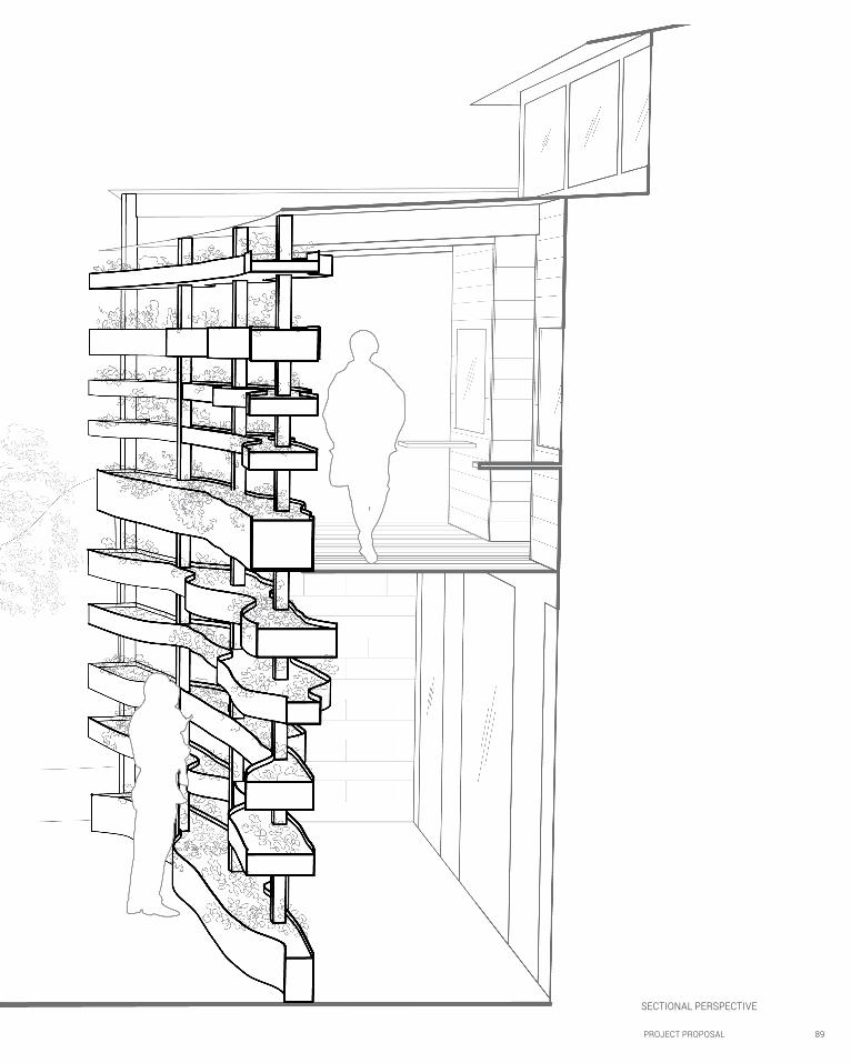
SECTIONAL PERSPECTIVE

90 PROJECT PROPOSAL
PROJECT PROPOSAL 91
92 PROJECT PROPOSAL
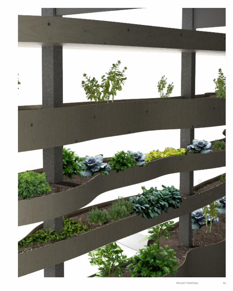
PROJECT PROPOSAL 93
94 PROJECT PROPOSAL
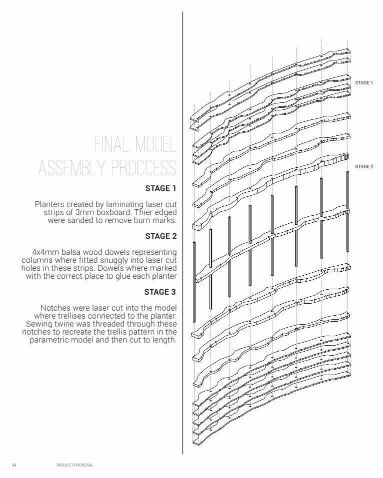
Final Model
Assembly proccessSTAGE 1
Planters created by laminating laser cut strips of 3mm boxboard. Thier edged
were sanded to remove burn marks.
STAGE 2
4x4mm balsa wood dowels representing columns where fitted snuggly into laser cut holes in these strips. Dowels where marked
with the correct place to glue each planter
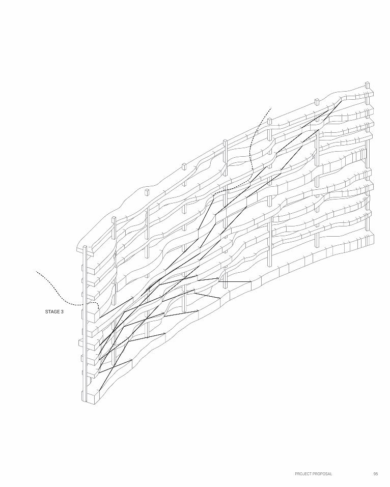
STAGE 3.
Notches were laser cut into the model where trellises connected to the planter.
Sewing twine was threaded through these notches to recreate the trellis pattern in the
parametric model and then cut to length.
STAGE 1
STAGE 2
PROJECT PROPOSAL 95
STAGE 3
96 PROJECT PROPOSAL
Final MoDel
OUTCOMES
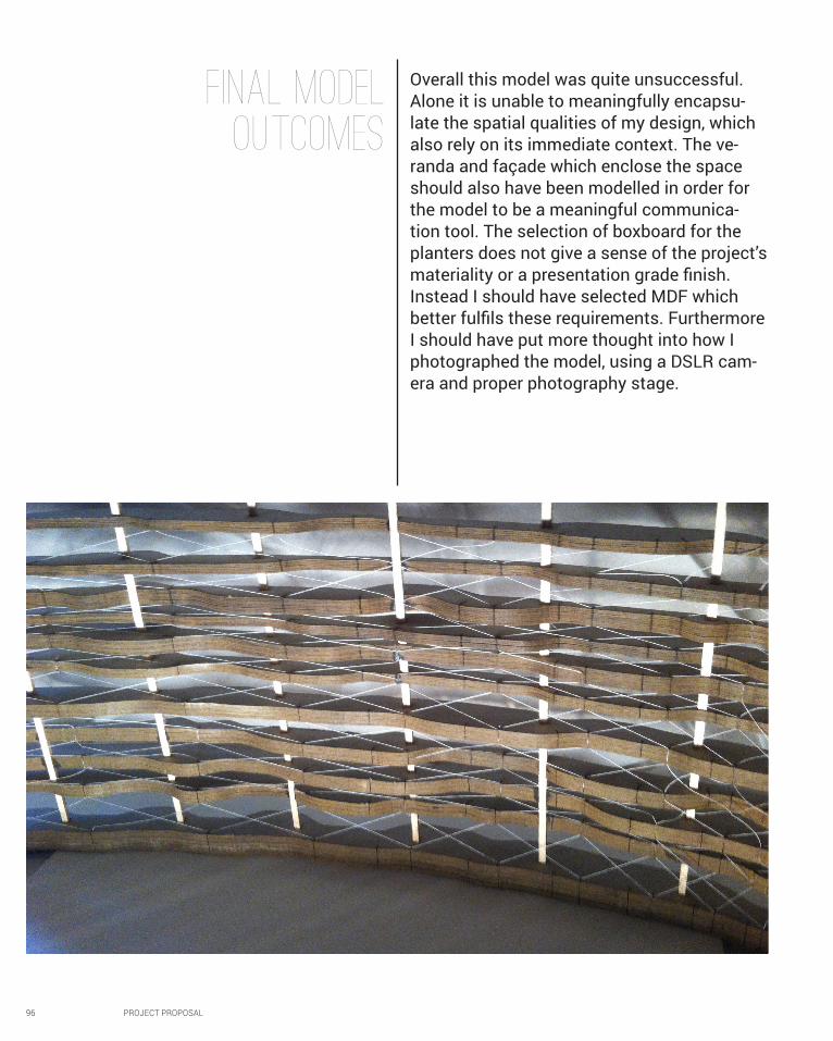
Overall this model was quite unsuccessful. Alone it is unable to meaningfully encapsu-late the spatial qualities of my design, which also rely on its immediate context. The ve-randa and façade which enclose the space should also have been modelled in order for the model to be a meaningful communica-tion tool. The selection of boxboard for the planters does not give a sense of the project’s materiality or a presentation grade finish. Instead I should have selected MDF which better fulfils these requirements. Furthermore I should have put more thought into how I photographed the model, using a DSLR cam-era and proper photography stage.
PROJECT PROPOSAL 97
98 PROJECT PROPOSAL
C4 CONCLUSION
PROJECT PROPOSAL 99
There were a number of areas my design I identified as having potential for further development based on my own musing and the feedback from my final crit.
The first major area is the planters tectonic system. This should be further refined by including an efficient sub-surface watering system and washes and outlets to prevent ponding. Secondly the structural system itself could be refined to reduce sag by replacing the steel flat bar with a different steel profile, and investigations could be made into innovative farming systems which require less soil.
The critic at my final presentation criticised the use of image sampling as essentially a way of generating arbitrary variation in the porosity of the planter wall. He argued the images were themselves arbitrary and illegible and therefore poorly used. In line with phenomenological thinking it was never my intent to embed specific legible images into the project, rather to create a rich sensory environment. While post-modern symbolism is irrelevant to my project, The feedback highlighted a major flaw in my methodology to me. Legibility implies an understanding on behalf the designer a
the relationship between the sampled image and final result. My selection of images is not founded on such an understanding and therefore a lacks of authorship and credibility. I tested only three images generated A Priori, without any refinement based on the shadow patterns they generated, clearly a flawed design process. This workflow ignores the iterative capacity which makes parametric modelling so powerful and curtails the potential of the shelves to effectively mimic dappled forest lighting. The design could be developed further by incrementally changing the sampled image in order to better understand its relationship with the shadow patterns generated and improving the image using this understanding. Furthermore the final curve profile was selected based on testing lighting at only a single time, far more extensive studies should have been carried out. The profile of the planter curves is therefore another area with great potential for improvement.
Finally, the scope of the project could be expanded so it wraps around a multiple buildings, creating far more productive agricultural space.
SCOPE FOR FURTHER DEVELOPMENT
LEARNING OBJECTIVES AND OUTCOMESWhile this sounds like a meaningless cliché, I have genuinely found Studio air both challenging and rewarding. As I have noted in earlier reflections, the readings and research required early weeks of the project was my first exposure to contemporary academic design theory. I am now able to make a case for my design proposals and evaluate other contemporary architectural proposals much more competently by referring to these theories. I have also developed my technical skills, especially with Grasshopper and V-Ray. I now find myself quickly flicking over to grasshopper in other projects, simply because it is often so much more efficient. I have also explored digital fabrication for the first time, gaining an understanding of the benefits and constraints of laser cutting. Comparing the model produced by hand for my interim presentation and my digitally fabricated final
model clearly illustrates the ability to digital fabrication to produce otherwise prohibitively complex geometry with a high degree of accuracy while saving enormous amounts of time. While I have definitely learnt a lot about digital fabrication my knowledge I could have achieved so much more. Exploring CNC routing would have been especially relevant to my project. Furthermore by producing only a single design prototype I did not fully engage with the exercise of refining my project through prototyping. I made and learnt from several mistakes, as I outlined in C2 and C3, but never followed up on this with an improved prototype. Finaly, while my theroetical interets shifted from a paramatric ‘second nature’ towards phenomenology and my project would need significant further refinement to achieve the sustainability goals set myself at the start of term overall i think overall it is one of my best.