Embed Size (px)
Citation preview

7. Peripherals
7.2 Peripheral handling
Computer Studies (AL)

Reference Silberschatz, Galvin, Gagne, “Operating System Concepts (sixth
edition)”, John Wiley and Sons, INC Hisao Yazawa, “學電腦運作原理的第一本書” , 博碩文化 William stallings, “Operating Systems Internals and Design
Principles (fourth edition)”, Prentice Hall Carl Hamacher, “Computer Organization”, McGraw Hill

Content Port Interrupts Direct Memory Access Polling I/O interface

When you boot up a computer System… When Computer is booted up, an bootstrap
program runs, which is usually stored in read-only memory(ROM)
It initializes all aspects of the system, from CPU registers to devices controllers to memory contents.

Computer-system Structure
CPUSystem bus
Memory Controller
Memory
Disk Controller Printer Controller
Disk Printer

How can a a processor give command? The controller has one or more registers
for data and control signals. The processor communicates with the
controller by reading and writing bit patterns in these registers.

Port Machine may connect to number of devices. The connector between the computer and the device is an
IC called I/O controller. There are several bytes of memory for temporary storage
in I/O controller called port. Note that it is different from registers in CPU.
One port can only support one device. Usual format:
IN <port name, port number> OUT <port name, port number>

An I/O port typically consists 4 registers. Status register contains bits indicated states such
as whether the current command has completed. (read by host)
Control register can be written by the host to start a command or change the mode of a device.
The data-in register is read by the host to get input.
The data-out register is written by the host to send output.

Memory-mapped I/O CPU has its own registers, which may be
updated by the instruction operated. If the device support this mechanism:
The device-control registers are mapped into the address space of the processor.
The CPU executes I/O requests using the standard data-transfer instructions to read and write the device-control registers.

Basis of Interrupts (1) System program used to test the device status. During testing period, processor is not performing any
useful computation. Tasks can be performed while waiting for an I/O device
to become ready. We can arrange for a hardware signal called an interrupt
to the processor. The signals is called Interrupt Request. At least one of the bus control lines, called an interrupt-
request line (INTR), is usually dedicated for this purpose.

Interrupt
Compute routine PRINT routine
1
2
i
i+1
m
Interrupt occurshere

Basis of Interrupt (2) The routine executed in response to an
interrupt request is called the interrupt-service routine (ISR).
The processor must inform the device that its request has been recognized, a special control signal, interrupt-acknowledge signal, is sent by CPU to accomplish the reorganization.

Basis of Interrupt (3) Before starting execution of the ISR, any information that may be
altered during the execution of that routine must be saved. The saving and restoring information can be done automatically by
the processor or program instructions. The processors save only the minimum amount of information
because the process of saving and restoring registers involves memory transfer which increase the total execution time.
The delay between the time an interrupt request is received and the start of execution of ISR is called interrupt latency.

I/O Interrupts To start an I/O operation, the CPU loads
the appropriate registers within the device controller.
The controller examines the contents of these registers to determine what action to take.

I/O Interrupt – Synchronous VS Asynchronous Synchronous: the I/O is started, then at I/O
completion, control is returned to the user process.
Asynchronous: it returns control to the use program without waiting for the I/O to complete. The I/O then can continue while other system operation occur.

I/O Interrupt – 2 types
Requesting process------waiting--------
Device driver
Interrupt handler
Hardware data transfer
time
Requesting process
Device driver
Interrupt handler
Hardware data transfer
time
Synchronous Asynchronous
Comparison – if we wait until complete, then If the CPU always waits for I/O
completion, at most one I/O request is outstanding at a time. The system knows exactly what device is
running. It excludes concurrent I/O operation to
several devices. It may overlap useful computation with I/O

Comparison – if return to main process, then If the starts the I/O and then continues the
process of OS or user program code. A system call is then needed to allow the user
program to wait for I/O completion. We also need to be able to keep track of
many I/O requests at the same time. OS uses a table containing an entry of each I/O
devices: the device-status table.

Interrupt hardware I/O requests an interrupt by activating a
bus line called interrupt-request line. (INTR)
Most computers are likely to have several I/O devices that can request an interrupt.
A single interrupt-request line may be used to serve n devices.

INTR

Handling Multiple devices 1. How can processor recognize the device
requesting an interrupt? 2. Given that different devices are likely to require
different interrupt-service routine, how can the processor obtain the starting address of the appropriate routine in each case?
3. Should a device be allowed to interrupt the processor while another interrupt is being serviced?
4. How should two or more simultaneous interrupt requests be handled?
1. Recognize the device The information needed to determine whether a
device is requesting an interrupt is available in its status register. Device raises interrupt request, SR = 1 (called IRQ
bit) The simplest way to identify the interrupt device is to
have the interrupt-service routine poll all the I/O devices connected to the bus.
Polling is easy to implement, but the time spent interrogating the IRQ buts of all the devices that may not be requesting any service.

2. Vectored Interrupt To reduce the time of the polling process, a
device requesting an interrupt may identify itself directly to the processor.
Then, the processor can immediately start executing the corresponding ISR.
This scheme called vectored interrupt.

2. Vectored Interrupt A device requesting an interrupt can identify itself by
sending a special code to the processor over the data bus. (also use bus control signals to ensure that devices do not interfere with each other)
The code represents the starting address of the interrupt-service routine for that device.
The processor reads this address, called the interrupt vector and loads it into the Program Counter (PC). The interrupt vector may also include a new value for the processor status register.

2. Vectored Interrupt Processor may not be ready to receive the interrupt-vector
code immediately. E.g. finish current instruction
The interrupting device must wait to put data on the bus only when the processor is ready to receive it.
When the processor is ready to receive the interrupt vector code, it activates the interrupt-acknowledge line, INTA.
The I/O device responds by sending its interrupt vector code and turn off the INTR signal.

3. Interrupt Nesting The interrupts should be disabled during the
execution of ISR, to ensure that a request from one device will not cause more than one interruption
If there are several devices, once a ISR is started, it always continues to completion before the processor accepts an interrupt request from a second device. It is acceptable to implement when the device with relatively short ISR is simple.

3 Interrupt nesting For some devices, however, a long delay in
responding to an interrupt request may lead to erroneous operation. (e.g. clock, high priority)
It may be necessary to accept an interrupt request from the clock during the execution of an ISR for another device.
3 Interrupt nesting I/O devices should be organized in a priority
structure. An interrupt request from a high-priority device
should be accepted while the processor is serving another request from a lower-priority device.
A multiple-level priority organization means that during execution of an ISR, interrupt requests will be accepted from some devices but not from others, depending upon the device’s priority.

3. Nested interrupt

4. Simultaneous Requests Common scheme is daisy chain.
4. Simultaneous Requests When several devices raise an interrupt
request and the INTR line is activated, the processor responds by setting the INTA line to 1.
Device 1 passes the signal on to device 2 only if it does not require any service.
The device that is electrically closest to the processor has the highest priority.

4. Simultaneous Requests
Devices are organized in groups, each group is connected at a different priority level.

Other cases of interrupt - exceptions Recovery from errors Debugging Privilege Exception
To protect the OS from user program, the privileged instructions may be used by the processor.

Details of ISR What is ISR doing?
Interrupt Service Routine (ISR)1. The device issues an interrupt signal to the
processor.
2. The processor finishes execution of the current instruction before responding the interrupt.
3. The processor tests for an interrupt, determines that there is one, and sends an acknowledgment signal to the device that issued the interrupt.

Interrupt Service Routine (ISR)4. The processor needs to prepare to transfer
control the interrupt routine. To begin, it needs to save information
needed to resume the current program at the point of interrupt. The minimum information required is the program status word (PSW) and the location of the next instruction to be executed, which is contained in the program counter.
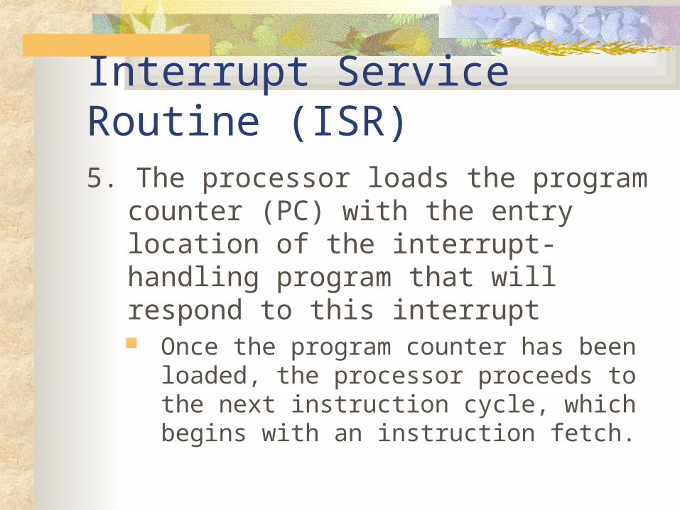
Interrupt Service Routine (ISR)5. The processor loads the program counter
(PC) with the entry location of the interrupt-handling program that will respond to this interrupt Once the program counter has been loaded,
the processor proceeds to the next instruction cycle, which begins with an instruction fetch.
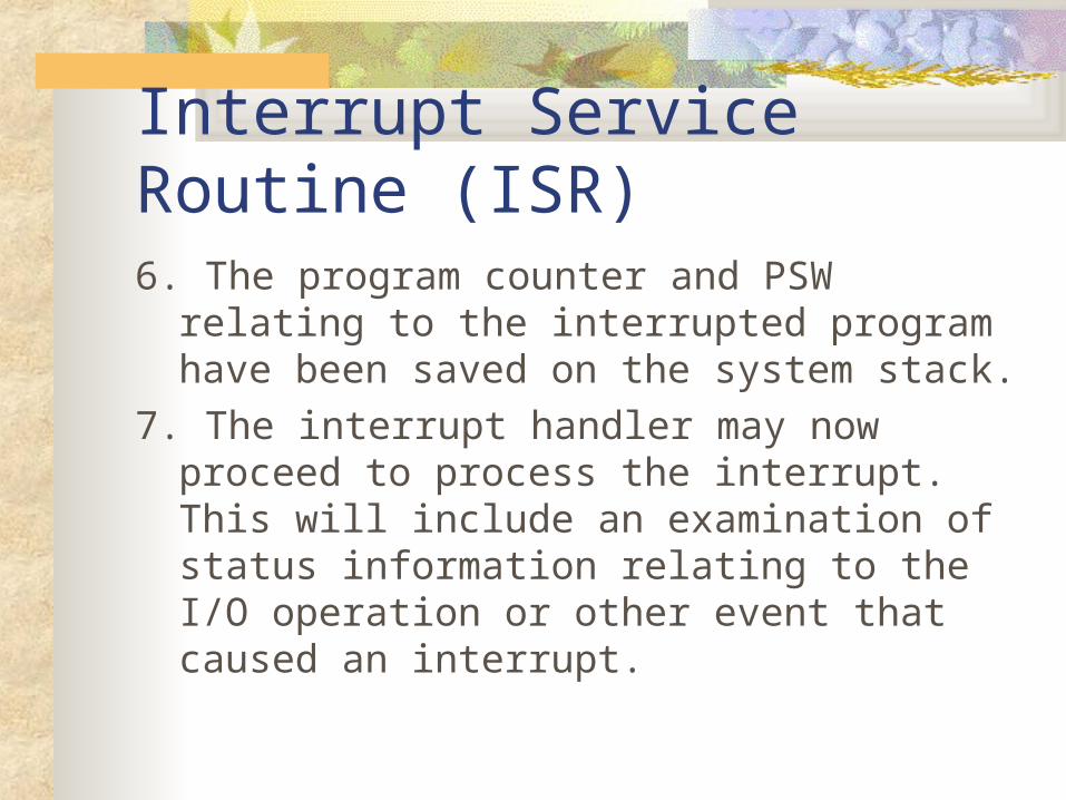
Interrupt Service Routine (ISR)6. The program counter and PSW relating to
the interrupted program have been saved on the system stack.
7. The interrupt handler may now proceed to process the interrupt. This will include an examination of status information relating to the I/O operation or other event that caused an interrupt.

Interrupt Service Routine (ISR)8. When interrupt processing is complete, the
saved register values are retrieved from the stack and restored to the registers.
9. The final act is to restore the PSW and program counter values from the stack. As a result, the next instruction to be executed will be from the previously interrupted program.

Interrupt masking Most CPU have two interrupt request lines. One is nonmaskable interrupt, which is reserved
for events such as unrecoverable memory errors. The second interrupt line is maskable. It can be
turned off by the CPU before the execution of critical instruction sequences that must not be interrupted.
The maskable interrupt is used by device controllers to request service.

Polling Instead of vectored interrupt, the task of identifying the device and determining the
starting address of the appropriate ISR may be implemented by software using polling. The controller indicates its state through the status register. (Busy: write a bit; Ready:
clear the bit) The host repeatedly reads the busy bit until that bit is clear. The host sets the write but in the command register and writes a byte into the data-out
register. The host sets the command-ready bit When the controller notices that the command-ready is set, it sets the busy bits. The controller reads the command register and sees the write command. It reads the
data-out register to get the byte, and does the I/O to the device. The controller clears the command-ready bit, clears the error but in the status register to
indicate that the device I/O succeeded, and clears the busy bit to indicate that it is finished.

Polling Main program should check the IRQ from the
devices from time to time. The status of checking the status of the devices is
called polling. Polling is suitable to the system with less number of
interrupt. Consider Mouse and keyboard has an IRQ at the same
time. (Not suitable) Consider a printer has an IRQ for printing, since output
time is long, CPU may not need to check the device frequently until an other IRQ is sent by the device.

Direct Memory Access (DMA) Devices with DMA can access the memory
of the computer system without involving the CPU.
CPU
Memory
Device without DMA
Device with DMA

Advantages of using DMA Reduce the workload of CPU Reduce the time to write the data to the
memory.

Port, IRQ and DMA Each device should have its own I/O
controller (port number), IRQ or DMA. It is not a must for a device to have these three controls at the same time.
Different devices with same control (port, IRQ or DMA) may cause system failure.
Standard I/O interface Peripheral Component Interconnect (PCI)
Bus SCSI Bus Universal Serial Bus (USB)
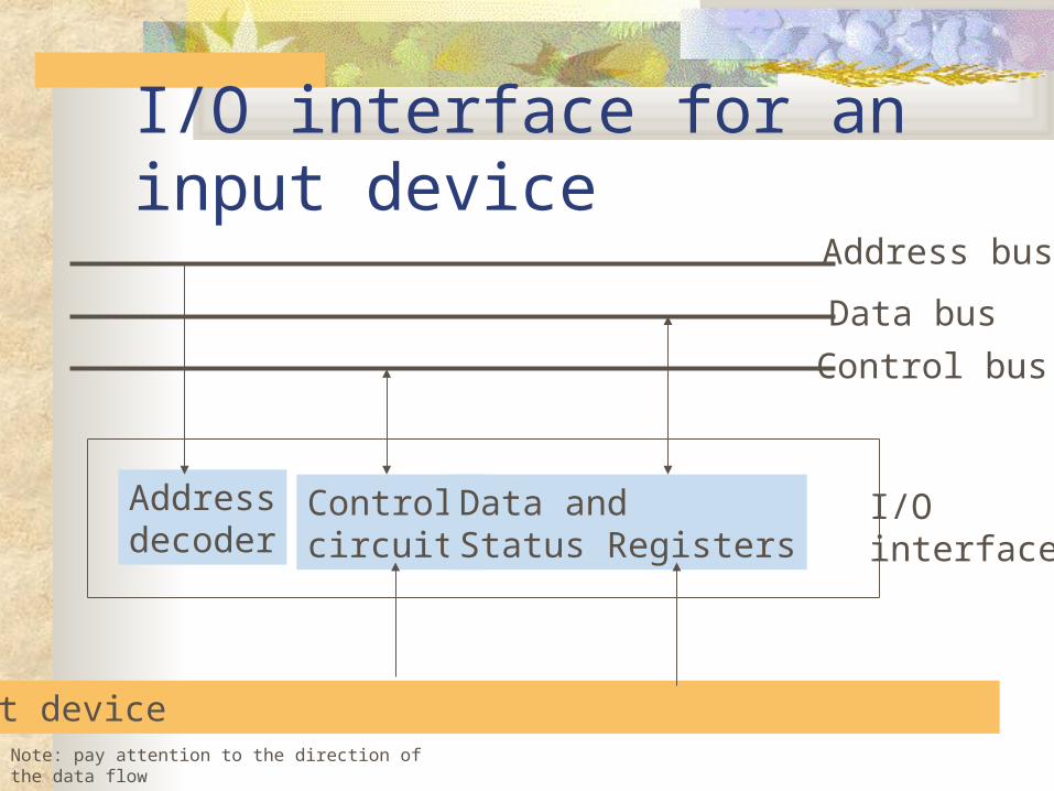
I/O interface for an input deviceAddress bus
Data bus
Control bus
Addressdecoder
Controlcircuits
Data andStatus Registers
Input device
I/Ointerface
Note: pay attention to the direction of the data flow

Remark on I/O interface for an input device The address decoder enables the device to
recognize its address. The data register holds the data being
transferred to or from the processor. The control circuit coordinate I/O transfers.
Remarks: refer to p206-207 example
Buffer A buffer is an area of memory for holding
data during I/O transfer. Buffering is a method of overlapping the
I/O of a job with its own computation.

Double buffering technique I/O device first put the data to buffer1, and
then call the processor to access the data. During the processor access the data, I/O
device may send the rest data to buffer2.

Example of displaying image Two important concepts used in many
games and multimedia applications are double buffering and page flipping. Programmers primarily use these techniques for two purposes:
to keep the user from seeing objects being drawn onto the screen
to eliminate flickering.
Example of displaying image Instead of drawing directly to video
memory, the program draws everything to a double buffer. When finished, the program copies the double buffer to video memory all at once. At that point the program clears the double buffer (if necessary) and the process starts over.