Embed Size (px)
Citation preview
1
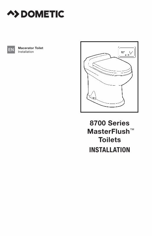
8700 Series MasterFlush™
ToiletsINSTALLATION
Macerator Toilet Installation . . . . . . . . . . . . . . . . . . . . . 3EN
Mazerier-WC Installation . . . . . . . . . . . . . . . . . . . . 13DE
WC dilacérateur Installation . . . . . . . . . . . . . . . . . . . . 23FR
Inodoro triturador Instalación . . . . . . . . . . . . . . . . . . . . 32ES
Toilet met versnijdingspomp Installatie . . . . . . . . . . . . . . . . . . . . . 41NL
WC di macerazione Installazione . . . . . . . . . . . . . . . . . . . 50IT
Silppuripumppu-wc Asennus . . . . . . . . . . . . . . . . . . . . . . 59FI
Macerator-toalett Installation . . . . . . . . . . . . . . . . . . . . 68SV
Findelingstoilet Installation . . . . . . . . . . . . . . . . . . . . 77DA
Macerator-toalettMontering . . . . . . . . . . . . . . . . . . . . . 86NO
2
Dometic 8700 Series MasterFlush Toilet
A
A
B C
D
E
F
B
C D
F
E
G I
J
K
HN
L
M
A
A
C
B
B
C
1
4
5
3
1 2
43
2
12
4
5
6 7
8
9
1110
3
3
Dometic 8700 Series MasterFlush Toilet Notes on using the manual
1 Notes on using the manual . . . . . . . . . . . . . . . . . . . . . . . . . . . . . . . . . . . . . . . . . . . . . . . . . 32 General safety instructions . . . . . . . . . . . . . . . . . . . . . . . . . . . . . . . . . . . . . . . . . . . . . . 3 - 43 Components . . . . . . . . . . . . . . . . . . . . . . . . . . . . . . . . . . . . . . . . . . . . . . . . . . . . . . . . . . . . 54 Specifications . . . . . . . . . . . . . . . . . . . . . . . . . . . . . . . . . . . . . . . . . . . . . . . . . . . . . . . . . . . 65 Installation . . . . . . . . . . . . . . . . . . . . . . . . . . . . . . . . . . . . . . . . . . . . . . . . . . . . . . . . . . 7 - 136 Customer service . . . . . . . . . . . . . . . . . . . . . . . . . . . . . . . . . . . . . . . . . . . . . . . . . . . . . . . . 14 RV Installation Appendix . . . . . . . . . . . . . . . . . . . . . . . . . . . . . . . . . . . . . . . . . . . . . . . . . . 15
1 Notes on using the manual
Note Supplementary information for operating the device .
fig. 1 A, page 2 : This refers to an element in an illustration . In this example, item A in figure 1 on page 2 .
Caution! Safety Instruction: Failure to observe this instruction can cause material damage and impair the function of the device .
ENTable of contents
2 General safety instructionsThe manufacturer will not be held liable for claims for damage resulting from the following:
• Faulty assembly or connection
• Damage to the unit from mechanical influences, misuse or abuse
• Alterations to the unit without express written permission from the manufacturer
• Use for purposes other than those described in the operating manual
2.1 Warnings – marine applications
The following statements must be read and understood before installing, servicing and/or operating this product on a boat. Modification of this product may result in property damage.
Dometic recommends that a qualified marine technician or electrician install or service this product . Equipment damage, injury to personnel or death could result from improper installation . DOMETIC ACCEPTS NO RESPONSIBILITY OR LIABILITY FOR DAMAGE TO EQUIPMENT, OR PERSONAL INJURY OR DEATH THAT MAY RESULT FROM IMPROPER INSTALLATION, SERVICE OR OPERATION OF THIS PRODUCT .
4
Dometic 8700 Series MasterFlush ToiletGeneral safety instructions
Caution! Hazard of Flooding If toilet uses raw water for flushing at ANY time, a raw water pump controlled by an auto-matically operating demand switch MUST NOT be installed . If the onboard water valve or any plumbing connections were to leak, the automatically operated pump would start and could flood the boat . Failure to comply can cause loss of property and life .
Caution! Hazard of Flooding Before beginning any work on this product, be sure that all electrical power to the unit has been turned off and that seacocks are in the CLOSED or OFF position . Failure to do so can result in flooding which can cause loss of property and life .
Caution! Hazard of Shock or Fire Always use recommended fuse, circuit breaker and wire size . Failure to do so can result in fire that can cause the loss of property and life .
Caution! Overfilling the holding tank can create serious damage to the sanitation system, such as rupturing the holding tank and releasing tank contents into the bilge . To prevent this pos-sibility, Dometic recommends using the “full” tank shut-down relay in the toilet’s electronic control module . The “full” signal from the holding tank can be generated by an optional Dometic DTM01C tank monitor or DTM04 four-level tank monitor system .
Caution! Hazard of Flooding If toilet rim is below the waterline at ANY time (during any conditions of heel, load or trim) and is connected to ANY through-the-hull fittings, properly positioned ventilated (vented) loops MUST be installed in intake* or discharge piping to prevent potential back siphonage of seawater into the boat . Failure to do so can result in flooding which can cause loss of property and life . * if connected to raw water
Caution! Hazard of Flooding If toilet is connected to ANY through-the-hull fittings, ALL flexible hoses must be of marine sanitation quality and must be secured to ANY fittings (such as those at seacock, vented loop or toilet) with two stainless steel, worm-drive hose band clamps at each connection . Connections MUST be checked frequently for integrity . Failure to comply can result in flooding which can cause loss of property and life .
Caution! Hazard of Flooding If the toilet is connected to ANY through-the-hull fittings, properly installed seacocks MUST be installed in all piping connected to through-the-hull fittings . Seacocks MUST be easily accessible to all users of the toilet or secondary valves fitted in hoses where they are easily accessible . All valves MUST be full bore valves and of marine quality . Screw-to-close gate valves are not recommended . Failure to do so can result in flooding which can cause loss of property and life .
5
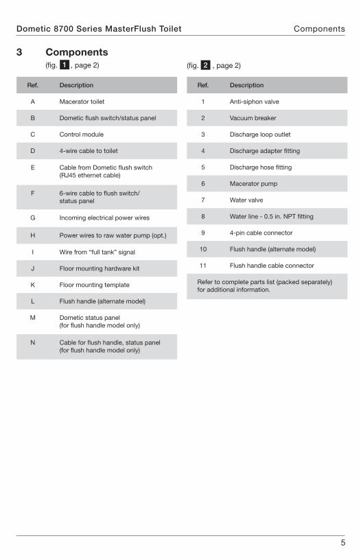
Dometic 8700 Series MasterFlush Toilet Components
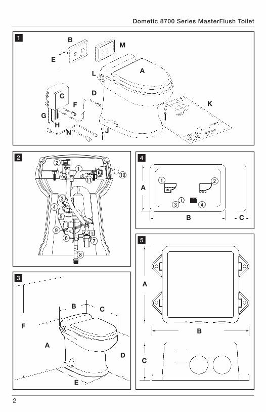
3 Components (fig . 1 , page 2)
Ref. Description
A Macerator toilet
B Dometic flush switch/status panel
C Control module
D 4-wire cable to toilet
E Cable from Dometic flush switch (RJ45 ethernet cable)
F 6-wire cable to flush switch/ status panel
G Incoming electrical power wires
H Power wires to raw water pump (opt .)
I Wire from “full tank” signal
J Floor mounting hardware kit
K Floor mounting template
L Flush handle (alternate model)
M Dometic status panel (for flush handle model only)
N Cable for flush handle, status panel (for flush handle model only)
Ref. Description
1 Anti-siphon valve
2 Vacuum breaker
3 Discharge loop outlet
4 Discharge adapter fitting
5 Discharge hose fitting
6 Macerator pump
7 Water valve
8 Water line - 0 .5 in . NPT fitting
9 4-pin cable connector
10 Flush handle (alternate model)
11 Flush handle cable connector
Refer to complete parts list (packed separately) for additional information .
(fig . 2 , page 2)
6
Dometic 8700 Series MasterFlush ToiletSpecifications
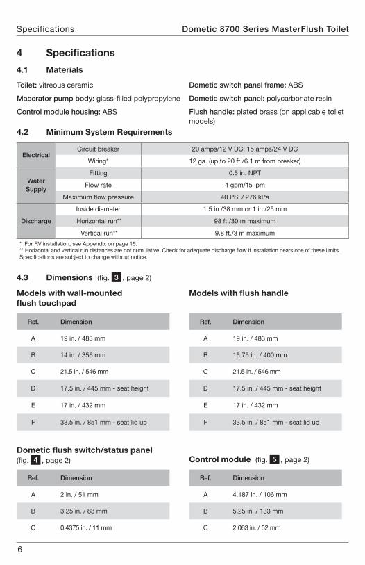
4.2 Minimum System Requirements
4.3 Dimensions (fig . 3 , page 2)
Ref. Dimension
A 19 in . / 483 mm
B 14 in . / 356 mm
C 21 .5 in . / 546 mm
D 17 .5 in . / 445 mm - seat height
E 17 in . / 432 mm
F 33 .5 in . / 851 mm - seat lid up
Ref. Dimension
A 2 in . / 51 mm
B 3 .25 in . / 83 mm
C 0 .4375 in . / 11 mm
Ref. Dimension
A 19 in . / 483 mm
B 15 .75 in . / 400 mm
C 21 .5 in . / 546 mm
D 17 .5 in . / 445 mm - seat height
E 17 in . / 432 mm
F 33 .5 in . / 851 mm - seat lid up
Ref. Dimension
A 4 .187 in . / 106 mm
B 5 .25 in . / 133 mm
C 2 .063 in . / 52 mm
Models with wall-mounted flush touchpad
Dometic flush switch/status panel (fig . 4 , page 2)
Models with flush handle
Control module (fig . 5 , page 2)
4 Specifications
4.1 Materials
Toilet: vitreous ceramic
Macerator pump body: glass-filled polypropylene
Control module housing: ABS
Dometic switch panel frame: ABS
Dometic switch panel: polycarbonate resin
Flush handle: plated brass (on applicable toilet models)
ElectricalCircuit breaker 20 amps/12 V DC; 15 amps/24 V DC
Wiring* 12 ga . (up to 20 ft ./6 .1 m from breaker)
Water Supply
Fitting 0 .5 in . NPT
Flow rate 4 gpm/15 lpm
Maximum flow pressure 40 PSI / 276 kPa
Discharge
Inside diameter 1 .5 in ./38 mm or 1 in ./25 mm
Horizontal run** 98 ft ./30 m maximum
Vertical run** 9 .8 ft ./3 m maximum
* For RV installation, see Appendix on page 15 .** Horizontal and vertical run distances are not cumulative . Check for adequate discharge flow if installation nears one of these limits .Specifications are subject to change without notice .
7
Dometic 8700 Series MasterFlush Toilet Installation
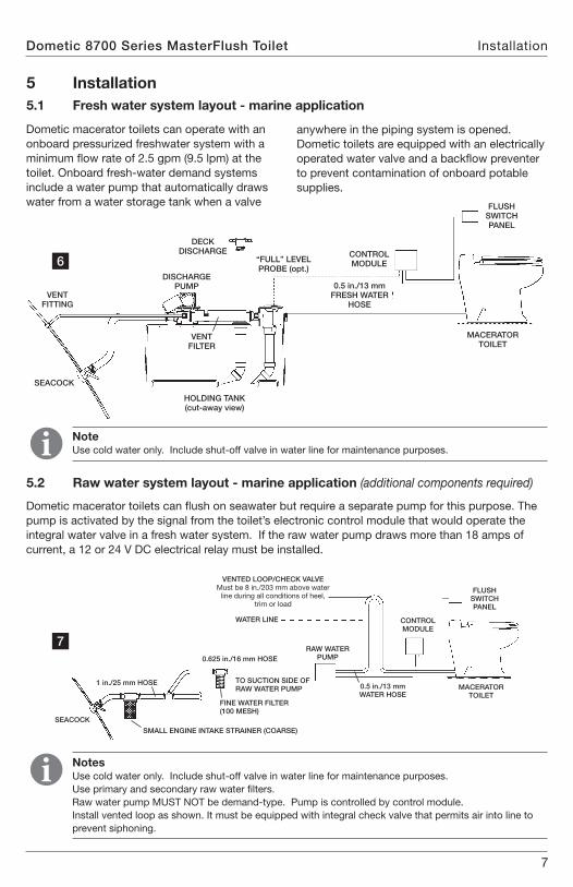
5 Installation5.1 Fresh water system layout - marine application
5.2 Raw water system layout - marine application (additional components required)
Note Use cold water only . Include shut-off valve in water line for maintenance purposes .
Notes Use cold water only . Include shut-off valve in water line for maintenance purposes . Use primary and secondary raw water filters . Raw water pump MUST NOT be demand-type . Pump is controlled by control module . Install vented loop as shown . It must be equipped with integral check valve that permits air into line to prevent siphoning .
Dometic macerator toilets can operate with an onboard pressurized freshwater system with a minimum flow rate of 2 .5 gpm (9 .5 lpm) at the toilet . Onboard fresh-water demand systems include a water pump that automatically draws water from a water storage tank when a valve
Dometic macerator toilets can flush on seawater but require a separate pump for this purpose . The pump is activated by the signal from the toilet’s electronic control module that would operate the integral water valve in a fresh water system . If the raw water pump draws more than 18 amps of current, a 12 or 24 V DC electrical relay must be installed .
anywhere in the piping system is opened . Dometic toilets are equipped with an electrically operated water valve and a backflow preventer to prevent contamination of onboard potable supplies .
6
7
VENT FITTING
SEACOCK
VENT FILTER
DISCHARGE PUMP
DECK DISCHARGE
“FULL” LEVEL PROBE (opt.)
CONTROL MODULE
CONTROL MODULE
MACERATOR TOILET
MACERATOR TOILET
FLUSH SWITCH PANEL
FLUSH SWITCH PANEL
0.5 in./13 mm FRESH WATER
HOSE
0.5 in./13 mm WATER HOSE
0.625 in./16 mm HOSE
1 in./25 mm HOSE
SEACOCK
TO SUCTION SIDE OF RAW WATER PUMP
FINE WATER FILTER (100 MESH)
SMALL ENGINE INTAKE STRAINER (COARSE)
RAW WATER PUMP
WATER LINE
HOLDING TANK (cut-away view)
VENTED LOOP/CHECK VALVE Must be 8 in ./203 mm above water
line during all conditions of heel, trim or load
8
Dometic 8700 Series MasterFlush ToiletInstallation
5.3 Toilet system with wall touchpad and through-the-floor connections - all applications
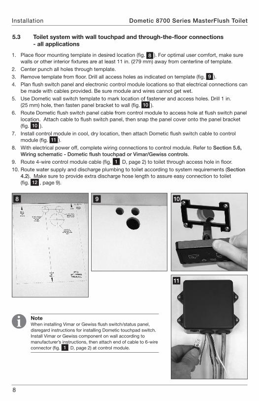
1 . Place floor mounting template in desired location (fig . 8 ) . For optimal user comfort, make sure walls or other interior fixtures are at least 11 in . (279 mm) away from centerline of template .
2 . Center punch all holes through template .3 . Remove template from floor . Drill all access holes as indicated on template (fig . 9 ) .4 . Plan flush switch panel and electronic control module locations so that electrical connections can
be made with cables provided . Be sure module and wires cannot get wet . 5 . Use Dometic wall switch template to mark location of fastener and access holes . Drill 1 in .
(25 mm) hole, then fasten panel bracket to wall (fig . 10 ) .6 . Route Dometic flush switch panel cable from control module to access hole at flush switch panel
location . Attach cable to flush switch panel, then snap the panel cover onto the panel bracket (fig . 10 ) .
7 . Install control module in cool, dry location, then attach Dometic flush switch cable to control module (fig . 11 ) .
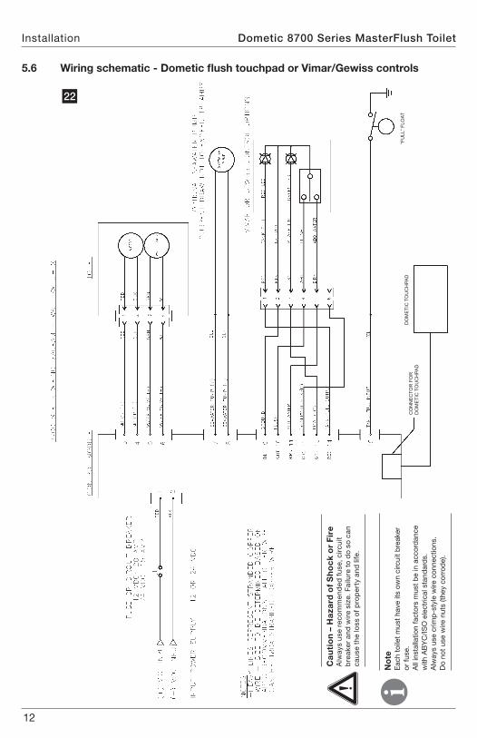
8 . With electrical power off, complete wiring connections to control module . Refer to Section 5.6, Wiring schematic - Dometic flush touchpad or Vimar/Gewiss controls .
9 . Route 4-wire control module cable (fig . 1 D, page 2) to toilet through access hole in floor .10 . Route water supply and discharge plumbing to toilet according to system requirements (Section
4.2) . Make sure to provide extra discharge hose length to assure easy connection to toilet (fig . 12 , page 9) .
8 9 10
Note When installing Vimar or Gewiss flush switch/status panel, disregard instructions for installing Dometic touchpad switch . Install Vimar or Gewiss component on wall according to manufacturer’s instructions, then attach end of cable to 6-wire connector (fig . 1 D, page 2) at control module .
11
9
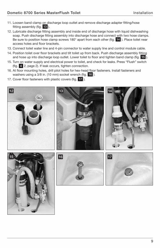
11 . Loosen band clamp on discharge loop outlet and remove discharge adapter fitting/hose fitting assembly (fig . 13 ) .
12 . Lubricate discharge fitting assembly and inside end of discharge hose with liquid dishwashing soap . Push discharge fitting assembly into discharge hose and connect with two hose clamps . Be sure to position hose clamp screws 180° apart from each other (fig . 14 ) . Place toilet near access holes and floor brackets .
13 . Connect toilet water line and 4-pin connector to water supply line and control module cable .14 . Position toilet over floor brackets and tilt toilet up from back . Push discharge assembly fitting
and hose up into discharge loop outlet . Lower toilet to floor and tighten band clamp (fig . 15 ) .15 . Turn on water supply and electrical power to toilet, and check for leaks . Press “Flush” switch
(fig . 4 2, page 2) . If leak occurs, tighten connection .16 . At floor mounting holes, drill pilot holes for hex-head floor fasteners . Install fasteners and
washers using a 3/8 in . (10 mm) socket wrench (fig . 16 ) .17 . Cover floor fasteners with plastic covers (fig . 17 ) .
Dometic 8700 Series MasterFlush Toilet Installation
12
15 16 17
1413
10
Dometic 8700 Series MasterFlush ToiletInstallation
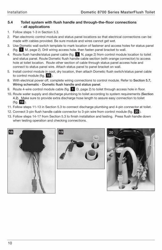
5.4 Toilet system with flush handle and through-the-floor connections - all applications1 . Follow steps 1-3 in Section 5 .3 . 2 . Plan electronic control module and status panel locations so that electrical connections can be
made with cables provided . Be sure module and wires cannot get wet . 3 . Use Dometic wall switch template to mark location of fastener and access holes for status panel
(fig . 1 M, page 2) . Drill wiring access hole, then fasten panel bracket to wall .4 . Route flush handle/status panel cable (fig . 1 N, page 2) from control module location to toilet
and status panel . Route Dometic flush handle cable section (with orange connector) to access hole at toilet location . Route other section of cable through status panel access hole and connect to status panel wire . Attach status panel to panel bracket on wall .
5 . Install control module in cool, dry location, then attach Dometic flush switch/status panel cable to control module (fig . 18 ) .
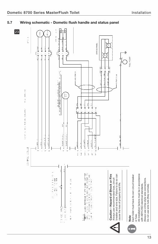
8 . With electrical power off, complete wiring connections to control module . Refer to Section 5.7, Wiring schematic - Dometic flush handle and status panel .
9 . Route 4-wire control module cable (fig . 1 D, page 2) to toilet through access hole in floor .10 . Route water supply and discharge plumbing to toilet according to system requirements (Section
4.2) . Make sure to provide extra discharge hose length to assure easy connection to toilet (fig . 19 ) .
11 . Follow steps 11-13 in Section 5 .3 to connect discharge plumbing and 4-pin connector at toilet .12 . Connect 3-pin flush handle cable connector to 3-pin wire from control module (fig . 20 ) .13 . Follow steps 14-17 from Section 5 .3 to finish installation and testing . Press flush handle down
when testing operation and checking connections .
18 2019
11
Dometic 8700 Series MasterFlush Toilet Installation
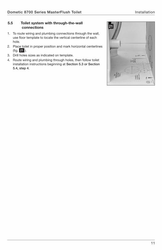
5.5 Toilet system with through-the-wall connections
1 . To route wiring and plumbing connections through the wall, use floor template to locate the vertical centerline of each hole .
2 . Place toilet in proper position and mark horizontal centerlines (fig . 21 ) .
3 . Drill holes sizes as indicated on template .4 . Route wiring and plumbing through holes, then follow toilet
installation instructions beginning at Section 5.3 or Section 5.4, step 4 .
21
12
DO
ME
TIC
TO
UC
HPA
DC
ON
NE
CTO
R F
OR
D
OM
ETI
C T
OU
CH
PAD
“FU
LL” F
LOAT
Dometic 8700 Series MasterFlush ToiletInstallation
Ca
uti
on
– H
aza
rd o
f S
ho
ck
or
Fir
e A
lway
s us
e re
com
men
ded
fus
e, c
ircu
it b
reak
er a
nd w
ire
size
. Fai
lure
to
do
so c
an
caus
e th
e lo
ss o
f pro
per
ty a
nd li
fe .
No
te
Eac
h to
ilet
mus
t ha
ve it
s ow
n ci
rcui
t b
reak
er
or fu
se .
All
inst
alla
tion
fact
ors
mus
t b
e in
acc
ord
ance
w
ith A
BY
C/I
SO
ele
ctric
al s
tand
ard
s .
Alw
ays
use
crim
p-s
tyle
wire
con
nect
ions
. D
o no
t us
e w
ire n
uts
(they
cor
rod
e) .
5.6 Wiring schematic - Dometic flush touchpad or Vimar/Gewiss controls
22
13
Dometic 8700 Series MasterFlush Toilet Installation
Ca
uti
on
– H
aza
rd o
f S
ho
ck
or
Fir
e A
lway
s us
e re
com
men
ded
fus
e, c
ircu
it b
reak
er a
nd w
ire
size
. Fai
lure
to
do
so c
an
caus
e th
e lo
ss o
f pro
per
ty a
nd li
fe .
No
te
Eac
h to
ilet
mus
t ha
ve it
s ow
n ci
rcui
t b
reak
er
or fu
se .
All
inst
alla
tion
fact
ors
mus
t b
e in
acc
ord
ance
w
ith A
BY
C/I
SO
ele
ctric
al s
tand
ard
s .
Alw
ays
use
crim
p-s
tyle
wire
con
nect
ions
. D
o no
t us
e w
ire n
uts
(they
cor
rod
e) .
5.7 Wiring schematic - Dometic flush handle and status panel
23
“FU
LL” F
LOAT
STA
TUS
PA
NE
L
14
Dometic 8700 Series MasterFlush ToiletCustomer Service
There is a strong, worldwide network to assist in servicing and maintaining your sanitation system . For the Authorized Service Center near you, please call from 8:00 a .m . to 5:00 p .m . (ET) Monday through Friday .
You may also contact or have your local dealer contact the Parts Distributor nearest you for quick response to your replacement parts needs . They carry a complete inventory for the Dometic product line .
Telephone: 1 800-321-9886 U .S .A . and Canada 330-439-5550 International
Fax: 330-496-3097 U .S .A . and Canada 330-439-5567 International
Web site: http://www .Dometic .com
6 Customer Service
15
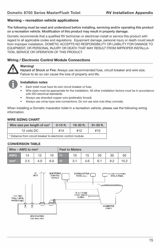
CONVERSION TABLE
Wire – AWG to mm2 Feet to Meters
AWG 14 12 10 Ft 10 15 20 30 50
mm2 2 .5 4 .0 6 .0 M 3 .1 4 .6 6 .1 9 .2 15 .2
Wire size per length of run* 0-15 ft. 16-30 ft. 31-50 ft.
12 volts DC #14 #12 #10
* Distance from circuit breaker to electronic control module .
WIRE SIZING CHART
When installing a Dometic macerator toilet in a recreation vehicle, please use the following wiring information .
Warning – recreation vehicle applications
The following must be read and understood before installing, servicing and/or operating this product on a recreation vehicle. Modification of this product may result in property damage.
Dometic recommends that a qualified RV technician or electrician install or service this product with regard to all applicable codes and regulations . Equipment damage, personal injury or death could result from improper installation . DOMETIC ACCEPTS NO RESPONSIBILITY OR LIABILITY FOR DAMAGE TO EQUIPMENT, OR PERSONAL INJURY OR DEATH THAT MAY RESULT FROM IMPROPER INSTALLA-TION, SERVICE OR OPERATION OF THIS PRODUCT .
Installation notes• Each toilet must have its own circuit breaker or fuse .• Wire sizes must be appropriate for the installation . All other installation factors must be in accordance
with ISO electrical standards .• Always use stranded copper wire (preferably tinned) .• Always use crimp-type wire connections . Do not use wire nuts (they corrode) .
Warning! Hazard of Shock or Fire: Always use recommended fuse, circuit breaker and wire size . Failure to do so can cause the loss of property and life .
Dometic 8700 Series MasterFlush Toilet RV Installation Appendix
Wiring / Electronic Control Module Connections
16
Dometic 8700 Series MasterFlush Toilet
Dometic is a customer-driven, world-leading provider of leisure products for the RV, automotive, truck and marine markets . We supply the industry and aftermarket with a complete range of air conditioners, refrigerators, awnings, cookers, sanitation systems, lighting, mobile power equipment, comfort and safety solutions, windows, doors and other equipment that make life more comfortable away from home .
Dometic supplies a wide range of workshop equipment for service and maintenance of built-in air conditioners . Dometic also provides specially designed refrigerators for hotel rooms, offices, wine storage and transport and storage of medical products .
Our products are sold in almost 100 countries and are produced mainly in wholly-owned production facilities around the world .
Dometic Corporation, Sanitation Division 13128 State Rt. 226, P.O. Box 38
Big Prairie, OH 44611 USA 1-800-321-9886 • Fax: 330-496-3097
www.Dometic.com
REVISION A Form No. 600346369 8/17 ©2017 Dometic Corporation