Embed Size (px)
DESCRIPTION
A Test Time Theorem a nd Its Applications. Praveen Venkataraman i [email protected] Suraj Sindia [email protected] Vishwani D. Agrawal [email protected] 14 th IEEE Latin-American Test Workshop Cordoba, Argentina April 5, 2013. Test Time Theorem. - PowerPoint PPT Presentation
Citation preview

A Test Time Theorem and Its Applications
Praveen [email protected]
Suraj [email protected]
Vishwani D. [email protected]
14th IEEE Latin-American Test WorkshopCordoba, Argentina
April 5, 2013
LATW 2013: A Test Time Theorem 2
Test Time Theorem
• Theorem: The test time (TT) for a synchronous test is the ratio of total energy dissipated in the entire test to the average power consumption during test.
• Quantitatively this can be written as
• Where ETOTAL is the total energy, an invariant of the test, PAVG is the average power.
4/5/2013
LATW 2013: A Test Time Theorem 3
History of This Work• V. D. Agrawal, “Pre-Computed Asynchronous Scan,” Invited Talk, LATW, April 2012.• P. Venkataramani and V. D. Agrawal, “Test Time Reduction in ATE Using
Asynchronous Clocking,” Poster, DFM&Y Workshop, June 2012.• V. D. Agrawal, “Reduced Voltage Test Can be Faster,” Elevator Talk, ITC, Nov 2012.• P. Venkataramani and V. D. Agrawal, “Reducing ATE Time for Power Constrained
Scan Test by Asynchronous Clocking,” Poster, ITC, Nov 2012.• P. Venkataramani and V. D. Agrawal, “Reducing Test Time of Power Constrained
Test by Optimal Selection of Supply Voltage,” Proc. 26th International Conf. VLSI Design, Jan 2013.
• P. Venkataramani, S. Sindia and V. D. Agrawal, “Finding Best Voltage and Frequency to Shorten Power-Constrained Test Time,” Proc. VTS, Apr 2013.
• P. Venkataramani and V. D. Agrawal, “Test Programming for Power Constrained Devices,” Proc. NATW, May 2013.
• P. Venkataramani and V. D. Agrawal, “ATE Test Time Reduction Using Asynchronous Clocking,” submitted to ITC, Sep 2013.
4/5/2013
LATW 2013: A Test Time Theorem 4
Applications of the Theorem
• Voltage and frequency scaling for minimum test time.
• Synchronous Test: Use a fixed clock frequency for the entire test.
• Asynchronous Test: Vary test clock vector by vector to dissipate the test energy at the fastest rate.
4/5/2013
LATW 2013: A Test Time Theorem 5
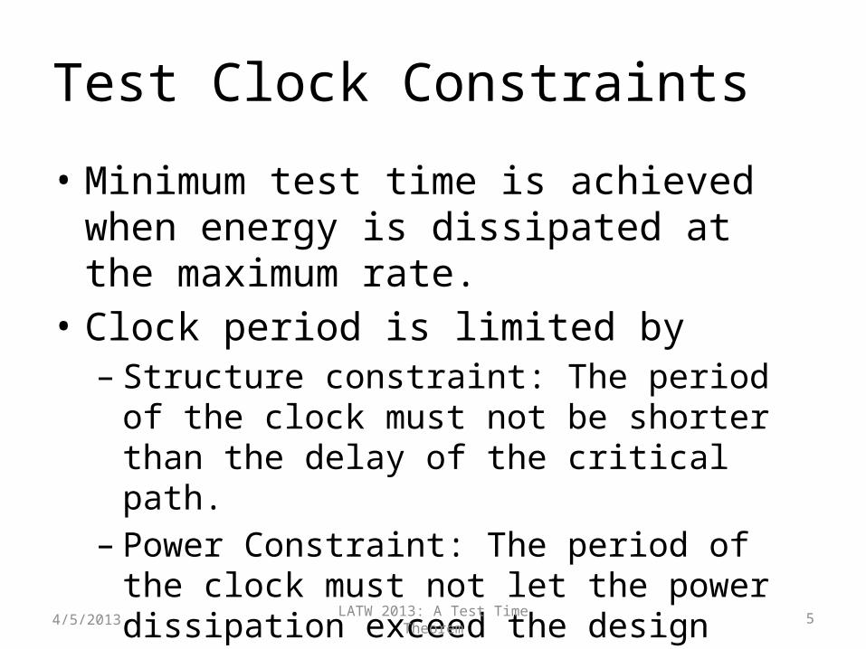
Test Clock Constraints
• Minimum test time is achieved when energy is dissipated at the maximum rate.
• Clock period is limited by – Structure constraint: The period of the clock must
not be shorter than the delay of the critical path.– Power Constraint: The period of the clock must
not let the power dissipation exceed the design specification.
4/5/2013
LATW 2013: A Test Time Theorem 6
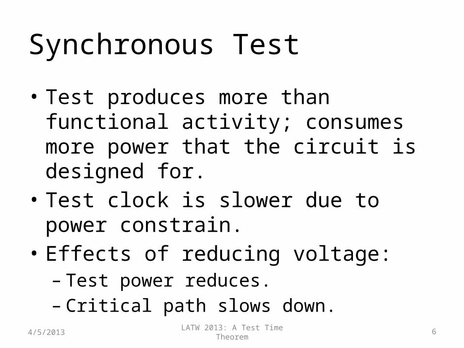
Synchronous Test
• Test produces more than functional activity; consumes more power that the circuit is designed for.
• Test clock is slower due to power constrain.• Effects of reducing voltage:– Test power reduces.– Critical path slows down.
4/5/2013
LATW 2013: A Test Time Theorem 7
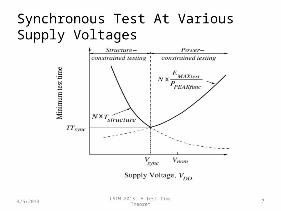
Synchronous Test At Various Supply Voltages
4/5/2013
LATW 2013: A Test Time Theorem 8
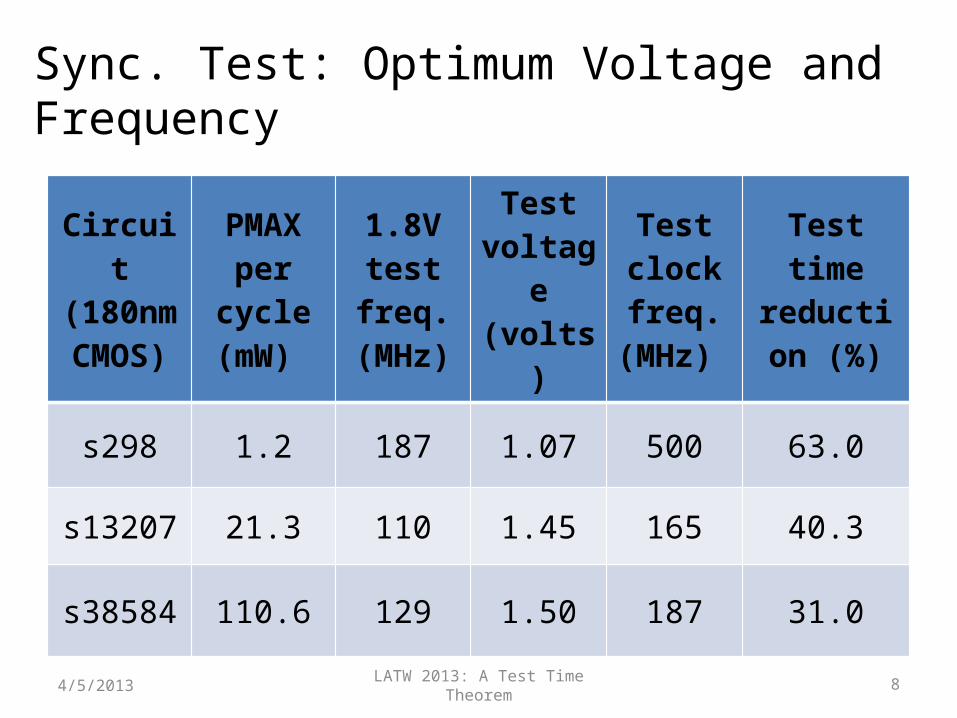
Sync. Test: Optimum Voltage and Frequency
Circuit (180nm CMOS)
PMAX per cycle
(mW)
1.8V test freq.
(MHz)
Test voltage (volts)
Test clock freq.
(MHz)
Test time reduction
(%)
s298 1.2 187 1.07 500 63.0
s13207 21.3 110 1.45 165 40.3
s38584 110.6 129 1.50 187 31.0
4/5/2013
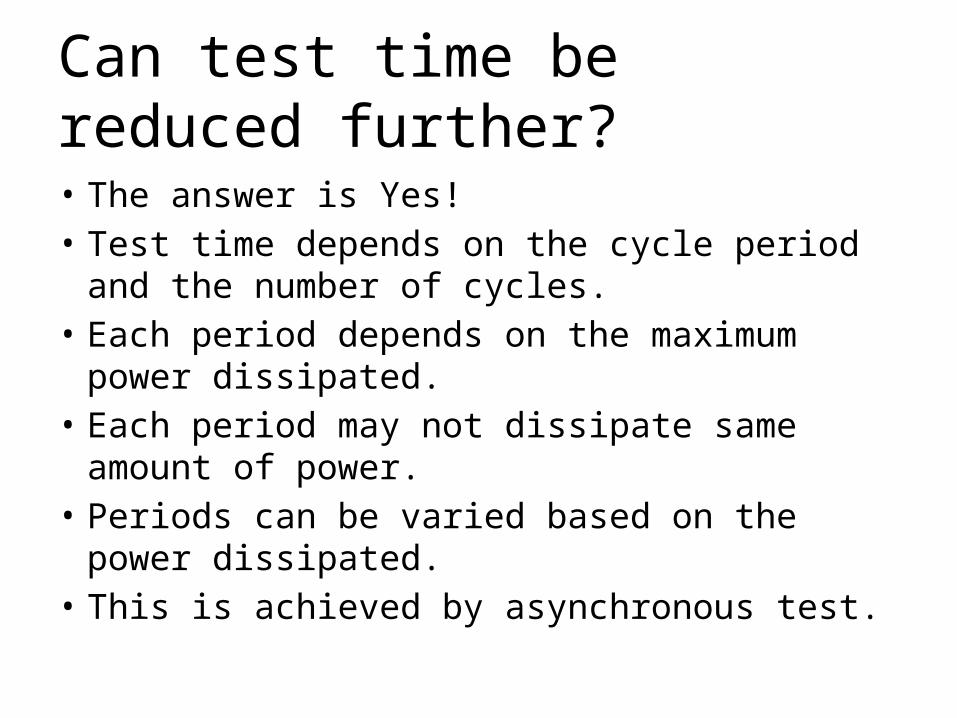
Can test time be reduced further?
• The answer is Yes!• Test time depends on the cycle period and the
number of cycles.• Each period depends on the maximum power
dissipated. • Each period may not dissipate same amount of
power.• Periods can be varied based on the power dissipated.• This is achieved by asynchronous test.
LATW 2013: A Test Time Theorem 10
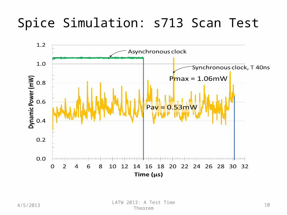
Spice Simulation: s713 Scan Test
4/5/2013
LATW 2013: A Test Time Theorem 11
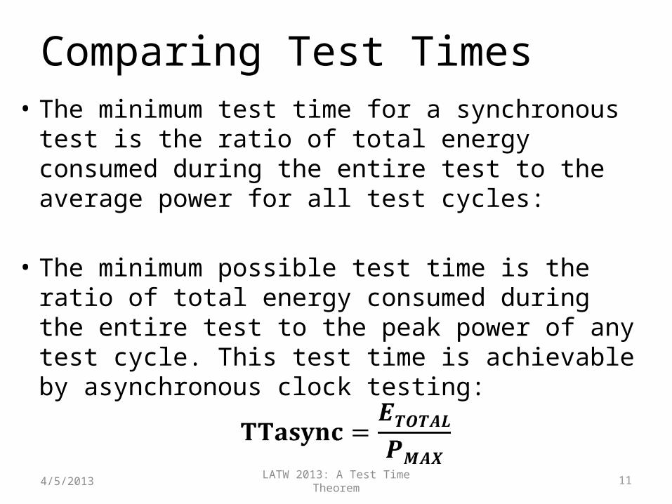
Comparing Test Times• The minimum test time for a synchronous test is
the ratio of total energy consumed during the entire test to the average power for all test cycles:
• The minimum possible test time is the ratio of total energy consumed during the entire test to the peak power of any test cycle. This test time is achievable by asynchronous clock testing:
4/5/2013
LATW 2013: A Test Time Theorem 12
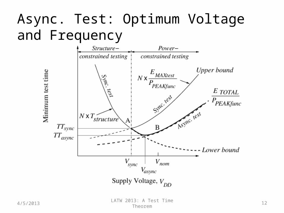
Async. Test: Optimum Voltage and Frequency
4/5/2013
LATW 2013: A Test Time Theorem 13
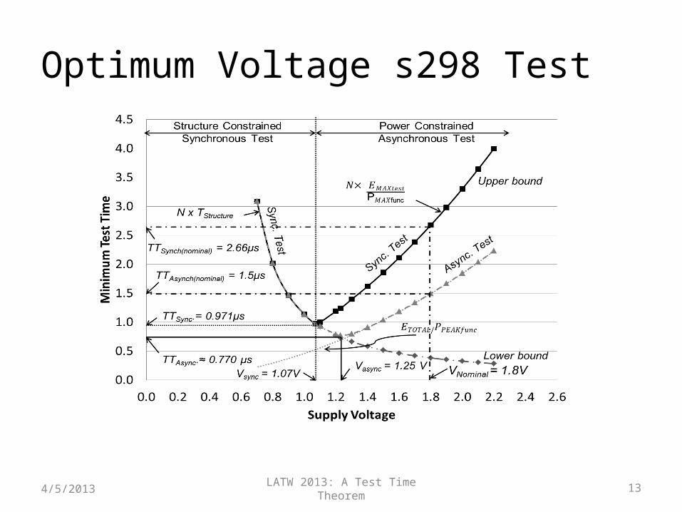
Optimum Voltage s298 Test
4/5/2013
LATW 2013: A Test Time Theorem 14
Asynchronous Test Feasibility on ATE
• Experimental Setup– The test was implemented on the Advantest T2000GS ATE at Auburn
University.– Maximum clock speed of 250 MHz– CUT is an FPGA configured for ISCAS‘89 benchmark circuit.– FPGA is configured on the run using the ATE.– All clock periods for asynchronous test are determined prior to external
test based on the amount of energy dissipated during each cycle.• Limitations in tester framework sets few margins to the clock
periods and the granularity in their variations– Latency due to analog measurement modules puts additional delay
overheads– Only 4 unique clock periods can be provided for each test flow
4/5/2013
LATW 2013: A Test Time Theorem 15
Asynchronous Periods
• Owing to the latency of the analog measurements the minimum clock period is 100ns.
• The asynchronous period achieved through simulation were multiplied by 100ns to provide clarity in the variations.
• The clock periods were grouped into 4 sets.• Each set contains patterns of one clock period.• For synchronous test the maximum period is used
as the fixed clock period.
4/5/2013
LATW 2013: A Test Time Theorem 16
Asynchronous Periods
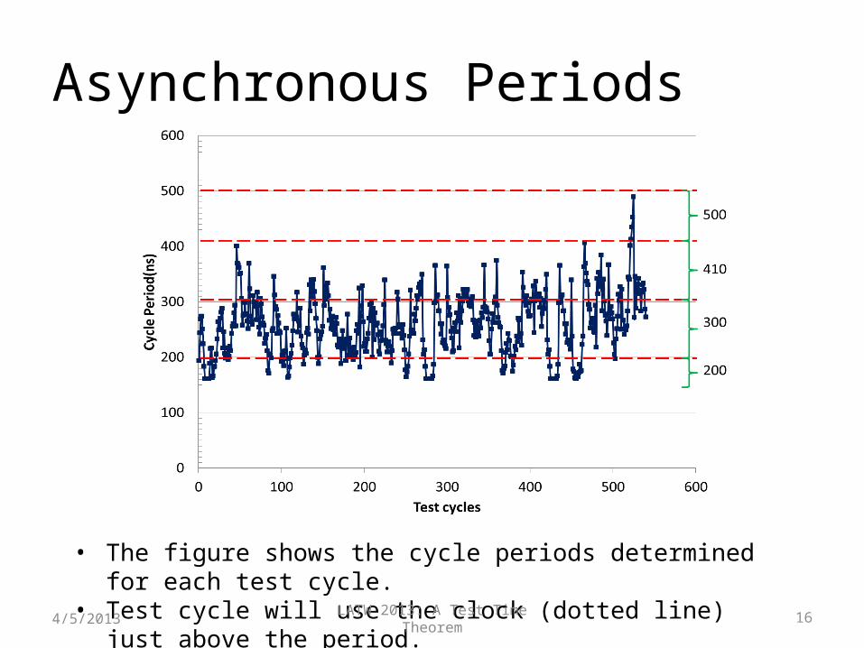
• The figure shows the cycle periods determined for each test cycle.• Test cycle will use the clock (dotted line) just above the period.
4/5/2013
LATW 2013: A Test Time Theorem 17
Test Program• Test plan is programmed using the native Open Test
Programming Language (OTPL).• Four unique periods and the corresponding information about
the signal behavior at each pin is provided in a timing file.• For each period, the input waveform of the clock is set to have
a 50% duty cycle.• The output is probed at the end of each period.• Within each period there is a time gap to apply primary inputs
(PI) and the clock edge to avoid race condition.• Period for each cycle is specified along with patterns.• Scan patterns are supplied sequentially bit by bit.
4/5/2013
LATW 2013: A Test Time Theorem 18
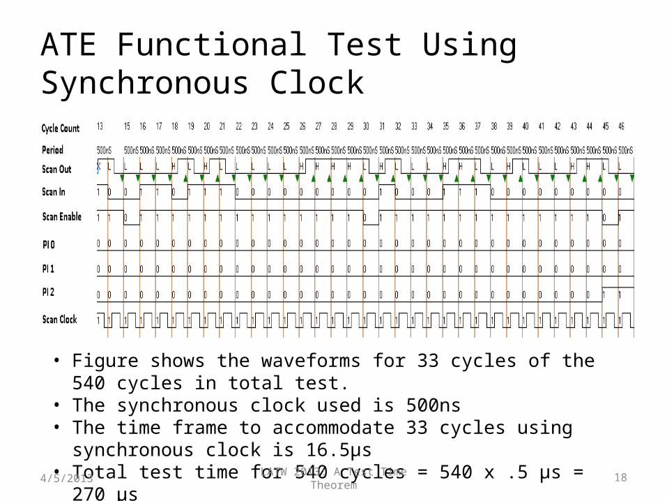
ATE Functional Test Using Synchronous Clock
• Figure shows the waveforms for 33 cycles of the 540 cycles in total test. • The synchronous clock used is 500ns• The time frame to accommodate 33 cycles using synchronous clock is
16.5µs• Total test time for 540 cycles = 540 x .5 µs = 270 µs
4/5/2013
LATW 2013: A Test Time Theorem 19
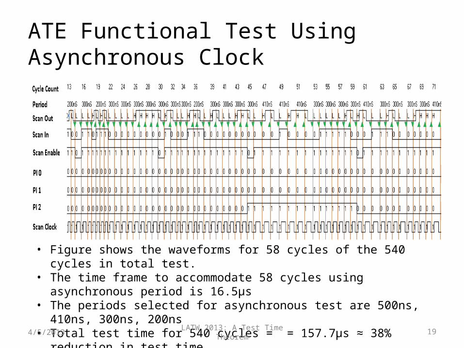
ATE Functional Test Using Asynchronous Clock
• Figure shows the waveforms for 58 cycles of the 540 cycles in total test. • The time frame to accommodate 58 cycles using asynchronous period is 16.5µs• The periods selected for asynchronous test are 500ns, 410ns, 300ns, 200ns• Total test time for 540 cycles = = 157.7µs ≈ 38% reduction in test time
4/5/2013
LATW 2013: A Test Time Theorem 20
Conclusion• The test time theorem provides limits of
attainable minimum test time, as
• Numerator can be reduced by lowering voltage.
• Denominator is increased by asynchronous clock.
4/5/2013