Embed Size (px)
Citation preview

7/24/2019 a4-avf-2004
http://slidepdf.com/reader/full/a4-avf-2004 1/15
Audi A4 Current Flow Diagram No. 22 / 1Edition 04.2005
1.9 l - Unit injectors (74 kW - 4 cylinder), engine code AVB from model year 2003
1.9 l - Unit injectors (96 kW - 4 cylinder), engine code AVF, AWX from model year 2003
Main fuse
On the battery
Fuse holder
Driver side dash panel
Page 1 of 15WI-XML

7/24/2019 a4-avf-2004
http://slidepdf.com/reader/full/a4-avf-2004 2/15
Fuse colours
30 A - green
25 A - white
20 A - yellow
15 A - blue
10 A - red
7,5 A - brown
5 A - beige
Note:
From fuse number 23 upwards the fuses in the fuse holder are designated as 223 in the Current Flow Diagram.
Coupling station with screw connection
In electronics box in plenum chamber
1 - 10-pin connector, black (T10)
2 - 10-pin connector, brown (T10a)
3 - 17-pin connector, red (T17d)6 - 17-pin connector, white (T17e)
Coupling station of A-pillar
Page 2 of 15WI-XML

7/24/2019 a4-avf-2004
http://slidepdf.com/reader/full/a4-avf-2004 3/15
Left bottom behind side trim
14 - 10-pin connector, grey (T10d)
4-point relay carrier
in electronics box in plenum chamber
in electronics box in plenum chamber
1.2 - Fuel pump relay (J17)
2 - Glow plug relay (J52)
3 - Terminal 30 voltage supply relay (J317)
A - Engine electronics fuse (S282)
B - Engine glow plug strip fuse (S39)
Fuse colours
15 A - blue
Page 3 of 15WI-XML

7/24/2019 a4-avf-2004
http://slidepdf.com/reader/full/a4-avf-2004 4/15
80 A - yellow
4-point relay carrier with screw connection
Driver side dash panel
3-point relay carrier
Driver side dash panel
2 - High heat output relay (J360)
3 - Low heat output relay (J359)
B - Auxiliary heater fuse (S126)
C - Auxiliary heater fuse 2 (S328)
Fuse colours
40 A - orange60 A - light blue
Page 4 of 15WI-XML
P 5 f 15WI XML

7/24/2019 a4-avf-2004
http://slidepdf.com/reader/full/a4-avf-2004 5/15
Note:
The position 1 in the relay carrier is not used.
Page 5 of 15WI-XML
Page 6 of 15WI XML

7/24/2019 a4-avf-2004
http://slidepdf.com/reader/full/a4-avf-2004 6/15
Audi A4 Current Flow Diagram No. 22 / 2
ws = whitesw = blackro = redrt = redbr = browngn = greenbl = bluegr = greyli = purplevi = purple
ge = yel lowor = orangers = pink
Battery, starter, alternator, voltage regulator,ignition/starter switch
A - BatteryB - Starter
C - Alternator
C1 - Voltage regulator
D - Ignition/starter switch
S5 - Fuse in fuse holder
S14 - Fuse in fuse holder
S88 - Strip fuse (main fuse)
S231 - Fuse in fuse holderT1d -
Single connector, black, left enginecompartment
T2 -
2-pin connector, black, in right enginecompartment
T10a -
10-pin connector, brown, coupling station onelectronics box, plenum chamber
11- Earth point, in battery box
500 - Screw connection 1 (30), on relay plate 501
- Screw connection 2 (30), on relay plate
A2-
Positive connection (15), in dash panel wiringharness
A32-
Positive connection (30), in dash panel wiringharness
A57-
Positive connection 3 (30), in dash panel wiringharness
* - for models with manual gearbox only
Page 6 of 15WI-XML
Page 7 of 15WI XML

7/24/2019 a4-avf-2004
http://slidepdf.com/reader/full/a4-avf-2004 7/15
Audi A4 Current Flow Diagram No. 22 / 3
ws = whitesw = blackro = redrt = redbr = browngn = greenbl = bluegr = greyli = purplevi = purple
ge = yel lowor = orangers = pink
Fuel pump relay, diesel direct injection system controlunit, terminal 30 voltage supply relay
J17 - Fuel pump relayJ248 - Diesel direct injection system control unit
J317 - Terminal 30 voltage supply relay
S126 - Auxiliary heater fuse
S228 - Fuse in fuse holder
S286 - Automatic gearbox fuse, run-on
S328 - Auxiliary heater fuse 2
T17e - 17-pin connector, white, coupling station onelectronics box, plenum chamber
12- Earth point, on left in engine compartment
83- Earth connection 1, in front right wiring harness
A98-
Positive connection 4 (30), in dash panel wiringharness
D173- Connection (87), in engine wiring harness
F33-
Positive connection (30), in diesel direct
injection system wiring harness* - for models with auxiliary air heater only
** - See Current Flow Diagram radiator fan
*** -
for models with automatic gearbox (multitronic01J) only
Page 7 of 15WI-XML
Page 8 of 15WI-XML

7/24/2019 a4-avf-2004
http://slidepdf.com/reader/full/a4-avf-2004 8/15
Audi A4 Current Flow Diagram No. 22 / 4
ws = whitesw = blackro = redrt = redbr = browngn = greenbl = bluegr = greyli = purplevi = purple
ge = yel lowor = orangers = pink
Accelerator position sender, fuel temperature sender,diesel direct injection system control unit, glow plugs -
(engine)F8 - Kick-down switch
F60 - Idling speed switch
G79 - Accelerator position sender
G81 - Fuel temperature sender
J52 - Glow plug relay
J59 - X-contact relief relay
J248 - Diesel direct injection system control unit
J293 - Radiator fan control unitQ6 - Glow plugs - (engine)
S39 - Engine glow plug strip fuse
T10 -
10-pin connector, black, coupling station onelectronics box, plenum chamber
T10d -
10-pin connector, grey, coupling station on leftof A-pillar
T17d -
17-pin connector, red, coupling station onelectronics box, plenum chamber
T17e -
17-pin connector, white, coupling station onelectronics box, plenum chamber
83- Earth connection 1, in front right wiring harness
A34- Connection (75x), in dash panel wiring harness
D16-
Connection (glow plugs), in front right wiringharness
Page 8 of 15WI XML
Page 9 of 15WI-XML
7/24/2019 a4-avf-2004
http://slidepdf.com/reader/full/a4-avf-2004 9/15
Audi A4 Current Flow Diagram No. 22 / 5
ws = whitesw = blackro = redrt = redbr = browngn = greenbl = bluegr = greyli = purplevi = purple
ge = yel lowor = orangers = pink
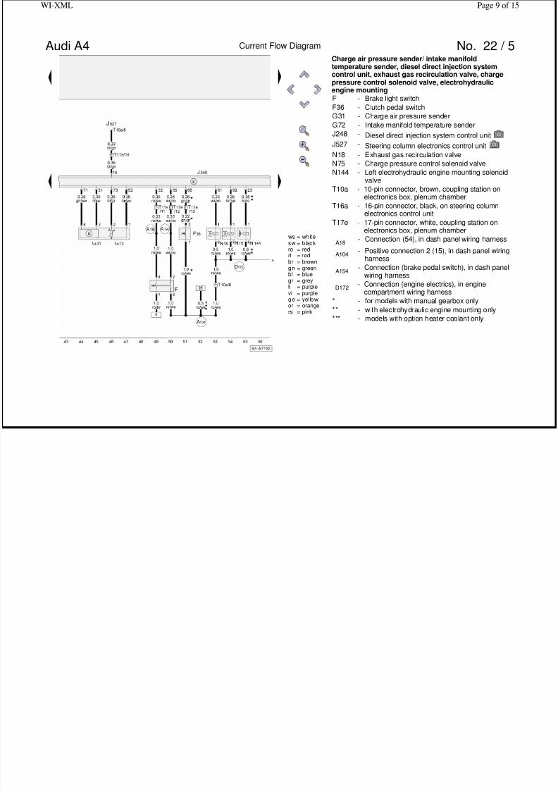
Charge air pressure sender/ intake manifoldtemperature sender, diesel direct injection system
control unit, exhaust gas recirculation valve, chargepressure control solenoid valve, electrohydraulicengine mountingF - Brake light switch
F36 - Clutch pedal switch
G31 - Charge air pressure sender
G72 - Intake manifold temperature sender
J248 - Diesel direct injection system control unit
J527 - Steering column electronics control unit
N18 - Exhaust gas recirculation valve
N75 - Charge pressure control solenoid valve
N144 -
Left electrohydraulic engine mounting solenoidvalve
T10a -
10-pin connector, brown, coupling station onelectronics box, plenum chamber
T16a -
16-pin connector, black, on steering columnelectronics control unit
T17e -
17-pin connector, white, coupling station onelectronics box, plenum chamber
A18- Connection (54), in dash panel wiring harness
A104-
Positive connection 2 (15), in dash panel wiringharness
A154-
Connection (brake pedal switch), in dash panelwiring harness
D172-
Connection (engine electrics), in enginecompartment wiring harness
* - for models with manual gearbox only** - with electrohydraulic engine mounting only
*** - models with option heater coolant only
Page 9 of 15WI XML
Page 10 of 15WI-XML

7/24/2019 a4-avf-2004
http://slidepdf.com/reader/full/a4-avf-2004 10/15
Audi A4 Current Flow Diagram No. 22 / 6
ws = whitesw = blackro = redrt = redbr = browngn = greenbl = bluegr = greyli = purplevi = purple
ge = yel lowor = orangers = pink
Hall sender, diesel direct injection system control unit,variable intake manifold flap change-over valve, unit
injector valvesG40 - Hall sender
J248 - Diesel direct injection system control unit
N79 - Heater element for crankcase breather
N239 - Variable intake manifold flap change-over valve
N240 - Unit injector valve, No. 1 cyl.
N241 - Unit injector valve, No. 2 cyl.
N242 - Unit injector valve, No. 3 cyl.
N243 - Unit injector valve, No. 4 cyl.
S282 - Engine electronics fuse
T8d - 8-pin connector, in engine compartment
T17d -
17-pin connector, red, coupling station onelectronics box, plenum chamber
83- Earth connection 1, in front right wiring harness
D172-
Connection (engine electrics), in enginecompartment wiring harness
* -
models with option bleeder heating for
crankcase only
g
Page 11 of 15WI-XML

7/24/2019 a4-avf-2004
http://slidepdf.com/reader/full/a4-avf-2004 11/15
Audi A4 Current Flow Diagram No. 22 / 7
ws = whitesw = blackro = redrt = redbr = browngn = greenbl = bluegr = greyli = purplevi = purplege = yel lowor = orangers = pink
Coolant temperature display sender, engine speedsender, air mass meter, diesel direct injection system
control unitG2 - Coolant temperature sender
G28 - Engine speed sender
G62 - Coolant temperature sender
G70 - Air mass meter
J234 - Airbag control unit
J248 - Diesel direct injection system control unit
T3 - 3-pin connector, grey, on engine block
T10a -
10-pin connector, brown, coupling station onelectronics box, plenum chamber
T17d -
17-pin connector, red, coupling station onelectronics box, plenum chamber
A70-
Connection (15a, fuse 231), in dash panelwiring harness
A125-
Connection (crash signal), in dash panel wiringharness
D51-
Positive connection 1 (15), in enginecompartment wiring harness
F27-
Connection (screening), in diesel direct injectionwiring harness
g
Page 12 of 15WI-XML

7/24/2019 a4-avf-2004
http://slidepdf.com/reader/full/a4-avf-2004 12/15
Audi A4 Current Flow Diagram No. 22 / 8
ws = whitesw = blackro = redrt = redbr = browngn = greenbl = bluegr = greyli = purplevi = purplege = yel lowor = orangers = pink
Diesel direct injection system control unit, auxiliary airheater element
J248 - Diesel direct injection system control unitJ359 - Low heat output relay
J360 - High heat output relay
T17d -
17-pin connector, red, coupling station onelectronics box, plenum chamber
Z35 - Auxiliary heating heater element
32- Earth point, on left behind dash panel
253- Earth connection, in heater unit wiring harness
F37-
Connection (auxiliary heater), in diesel directinjection system wiring harness
* - for models with auxiliary air heater only
Page 13 of 15WI-XML

7/24/2019 a4-avf-2004
http://slidepdf.com/reader/full/a4-avf-2004 13/15
Audi A4 Current Flow Diagram No. 22 / 9
ws = whitesw = blackro = redrt = redbr = browngn = greenbl = bluegr = greyli = purplevi = purplege = yel lowor = orangers = pink
Diesel direct injection system control unit, automaticgearbox control unit, control unit with display in dash
panel insertJ217 - Automatic gearbox control unit
J248 - Diesel direct injection system control unit
J285 -
Control unit with display in dash panel insert
T10a -
10-pin connector, brown, coupling station onelectronics box, plenum chamber
T16 - 16-pin connector, black, diagnostic connector
T17d -
17-pin connector, red, coupling station onelectronics box, plenum chamber
T32a - 32-pin connector, green, on dash panel insert
A76-
Connection (diagnosis wire K), in dash panelwiring harness
A121-
Connection (high bus), in dash panel wiringharness
A122-
Connection (low bus), in dash panel wiringharness
D159-
Connection (high bus), in engine compartmentwiring harness
D160-
Connection (low bus), in engine compartmentwiring harness
* -
for models with automatic gearbox (multitronic01J) only, up to model year 2003
** -
for models with automatic gearbox (multitronic01J) only, from model year 2004
● - Data bus wire (CAN bus)
Page 14 of 15WI-XML

7/24/2019 a4-avf-2004
http://slidepdf.com/reader/full/a4-avf-2004 14/15
Audi A4 Current Flow Diagram No. 22 / 10
ws = whitesw = blackro = redrt = redbr = browngn = greenbl = bluegr = greyli = purplevi = purplege = yel lowor = orangers = pink
Control unit with display in dash panel insert, fuelgauge sender, oil level and oil temperature sender
G - Fuel gauge senderG6 - Fuel pump (pre-supply pump)
G169 - Fuel gauge sender 2
G266 - Oil level and oil temperature sender
J285 -
Control unit with display in dash panel insert
K2 - Alternator warning lamp
K29 - Glow period warning lamp
T10 -
10-pin connector, black, coupling station on
electronics box, plenum chamberT10a -
10-pin connector, brown, coupling station onelectronics box, plenum chamber
T32 - 32-pin connector, blue, on dash panel insert
T32a - 32-pin connector, green, on dash panel insert
83- Earth connection 1, in front right wiring harness
249- Earth connection 2, in interior wiring harness
269-
Earth connection (sender earth) 1, in dash panel
wiring harness
A17- Connection (61), in dash panel wiring harness
A74-
Connection (15a, fuse 5), in dash panel wiringharness
* - for models with four-wheel drive only
Page 15 of 15WI-XML

7/24/2019 a4-avf-2004
http://slidepdf.com/reader/full/a4-avf-2004 15/15
Audi A4 Current Flow Diagram No. 22 / 11
ws = whitesw = blackro = redrt = redbr = browngn = greenbl = bluegr = greyli = purplevi = purplege = yel lowor = orangers = pink
Control unit with display in dash panel insert, oilpressure switch, coolant shortage indicator switch
F1 - Oil pressure switchF66 - Coolant shortage indicator switch
J285 -
Control unit with display in dash panel insert
T10 -
10-pin connector, black, coupling station onelectronics box, plenum chamber
T32 - 32-pin connector, blue, on dash panel insert
T32a - 32-pin connector, green, on dash panel insert
269-
Earth connection (sender earth) 1, in dash panel
wiring harness
327-
Earth connection (sender earth), in enginecompartment wiring harness