Embed Size (px)
Citation preview
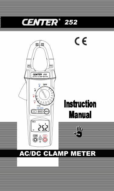
AC/DC CLAMP METER
252
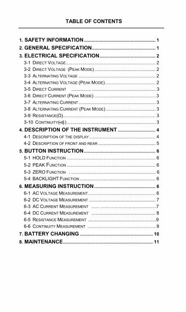
TABLE OF CONTENTS
1. SAFETY INFORMATION....................................................... 1 2. GENERAL SPECIFICATION................................................. 1 3. ELECTRICAL SPECIFICATION........................................... 2
3-1 DIRECT VOLTAGE..................................................................... 2 3-2 DIRECT VOLTAGE (PEAK MODE) ............................................... 2 3-3 ALTERNATING VOLTAGE ........................................................... 2 3-4 ALTERNATING VOLTAGE (PEAK MODE)....................................... 2 3-5 DIRECT CURRENT ............... ................................................. 3 3-6 DIRECT CURRENT (PEAK MODE) ............................................... 3 3-7 ALTERNATING CURRENT ........................................................... 3 3-8 ALTERNATING CURRENT (PEAK MODE) ...................................... 3 3-9 RESISTANCE(Ω)....................................................................... 3 3-10 CONTINUITY( ) .................................................................... 3
4. DESCRIPTION OF THE INSTRUMENT ............................. 4 4-1 DESCRIPTION OF THE DISPLAY................................................... 4 4-2 DESCRIPTION OF FRONT AND REAR ............................................ 5
5. BUTTON INSTRUCTION....................................................... 6 5-1 HOLD FUNCTION .................................................................... 6 5-2 PEAK FUNCTION .................................................................... 6 5-3 ZERO FUNCTION . ................................................................. 6 5-4 BACKLIGHT FUNCTION .......................................................... 6
6. MEASURING INSTRUCTION ............................................... 6 6-1 AC VOLTAGE MEASUREMENT.................................................... 6 6-2 DC VOLTAGE MEASUREMENT ................................................... 7 6-3 AC CURRENT MEASUREMENT ...... ...........................................7 6-4 DC CURRENT MEASUREMENT ................................................. 8 6-5 RESISTANCE MEASUREMENT ....................................................9 6-6 CONTINUITY MEASUREMENT .....................................................9
7. BATTERY CHANGING ........................................................ 10 8. MAINTENANCE..................................................................... 11
Clamp Meter
1
1. SAFETY INFORMATION
Do not operate the tester if the body of meter or the test lead look broken. Check the main function dial and make sure it is at the correct position before each measurement. Do not perform resistance and continuity test on a live power system. Do not apply voltage between the test terminals and test terminal to ground that exceed the maximum limit record in this manual. Keep the fingers after the protection ring when measuring through the test lead. Chang the battery when the symbol appears to avoid incorrect data.
Environmental Conditions Operation Temperature: 0°C to 40°C(32°F to 104°F); < 70 % RH Storage Temperature: -10°C to 60°C(14°F to 140°F); < 80 % RH
Explanation Symbols
Attention refer to operation Instructions.
Dangerous voltage may be present at terminals.
This instrument has double insulation.
Approvals: EN61010 600V CAT III 2. GENERAL SPECIFICATION
Digital Display: 4 digital liquid crystal (LCD), Maximum reading 6200. Polarity: When a negative signal is applied, the signal appears. Low Battery Indication: When the battery is under the proper operation range, will appear on the LCD display. Sample Rate: 3 times/sec.
Clamp Meter
2
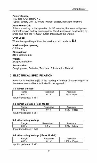
Power Source: 1.5V size AAA battery X 2 Typical battery Life: 50 hours (without buzzer, backlight function) Auto Power Off: If there is no key or dial operation for 30 minutes, the meter will power itself off to save battery consumption. This function can be disabled by press and hold the “ HOLD” button then power the unit on. Over Load: When the signal larger than the maximum will be show . Maximum jaw opening: ∅ 25 mm Dimensions: 210 x 62 x 36 mm Weight: 273g (with battery) Accessories: Carrying case, Batteries, Test Lead & Instruction Manual.
3. ELECTRICAL SPECIFICATION
Accuracy is to within ± [% of the reading + number of counts (dgts)] in the reference conditions indicated in the appendix.
3-1 Direct Voltage
Range Resolution Accuracy 600 V 0.1 V 1% + 2dgts
Input impedance: 1 MΩ
3-2 Direct Voltage ( Peak Model ) Range Resolution Accuracy 600 V 0.1 V 1.5% + 8dgts
Input impedance: 1 MΩ
3-3 Alternating Voltage Range Resolution Accuracy 600 V 0.1 V 1.2% + 5dgts
Input impedance: 1 MΩ
3-4 Alternating Voltage ( Peak Model ) Range Resolution Accuracy 600 V 0.1 V 1.7% + 10dgts
Input impedance: 1 MΩ
Clamp Meter
3
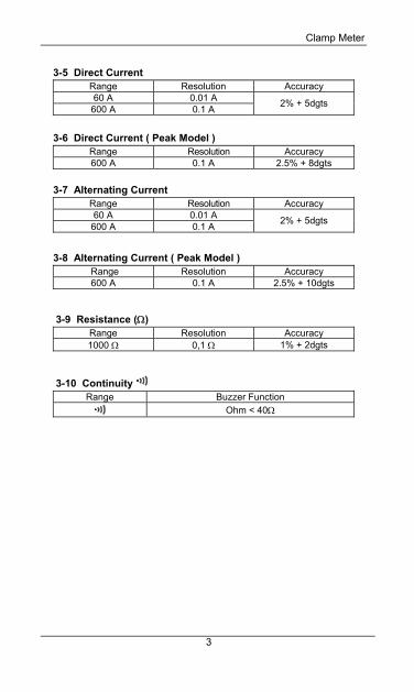
3-5 Direct Current Range Resolution Accuracy 60 A 0.01 A 600 A 0.1 A 2% + 5dgts
3-6 Direct Current ( Peak Model )
Range Resolution Accuracy 600 A 0.1 A 2.5% + 8dgts
3-7 Alternating Current Range Resolution Accuracy 60 A 0.01 A 600 A 0.1 A 2% + 5dgts
3-8 Alternating Current ( Peak Model ) Range Resolution Accuracy 600 A 0.1 A 2.5% + 10dgts
3-9 Resistance (Ω) Range Resolution Accuracy 1000 Ω 0,1 Ω 1% + 2dgts
3-10 Continuity Range Buzzer Function
Ohm < 40Ω
Clamp Meter
4
4. DESCRIPTION OF THE INSTRUMENT
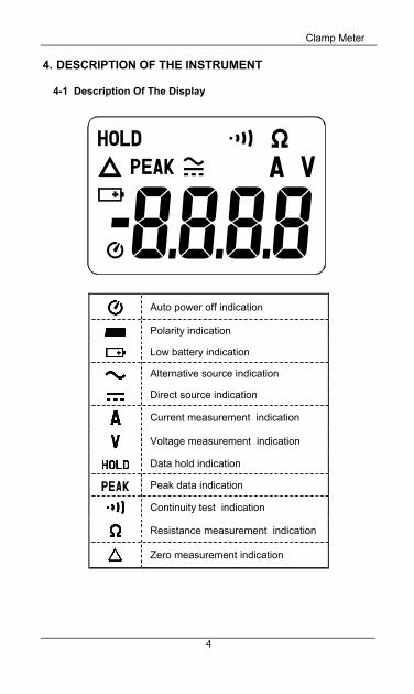
4-1 Description Of The Display
Auto power off indication
Polarity indication
Low battery indication
Alternative source indication
Direct source indication
Current measurement indication
Voltage measurement indication
Data hold indication
Peak data indication
Continuity test indication
Resistance measurement indication
Zero measurement indication
Clamp Meter
5
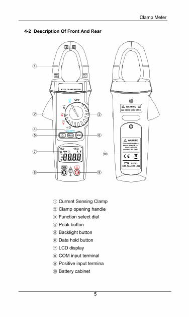
4-2 Description Of Front And Rear
1 Current Sensing Clamp 2 Clamp opening handle
3 Function select dial 4 Peak button 5 Backlight button 6 Data hold button 7 LCD display 8 COM input terminal 9 Positive input termina 10 Battery cabinet
Clamp Meter
6
5. BUTTON INSTRUCTION
5-1 HOLD Function It is possible to freeze the value displayed by pressing on the "HOLD" button. To deactivate this function, press the "HOLD" button a second time.
5-2 PEAK Function
If you press on the "PEAK" button , the display will show "PEAK" symbol. When there is a value input that value will be indicated frozen in the display. If a bigger peak value is input, the peak value will be updataed and indicated frozen in the display. When you press on the button again, the function will return to the normal mode.
5-3 Zero Function If you press and hold the "PEAK" button for 2 seconds or longer, the display will show " " symbol. When you turn on this function, the reading will become zero. When you press on the button again, the function will return to the normal mode.
5-4 BACKLIGHT Function If you press on the“ " button, it will turn on the backlight function.(The backlight is blue light. When you turn on this function, it will light for 15 seconds) If you press on the“ "button again, the function will be turned off.
6. MEASURING INSTRUCTION
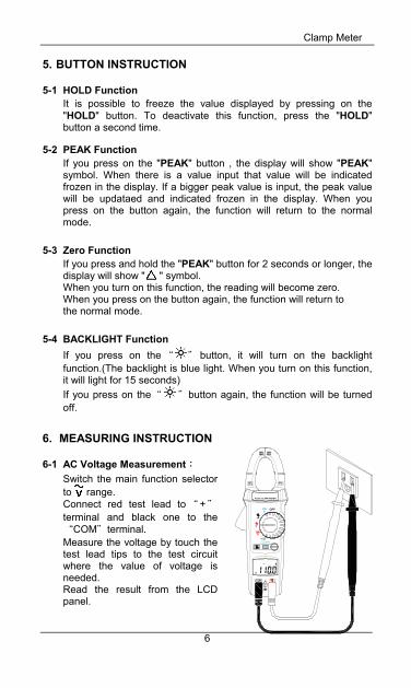
6-1 AC Voltage Measurement: Switch the main function selector to range. Connect red test lead to“ +"
terminal and black one to the “COM"terminal. Measure the voltage by touch the test lead tips to the test circuit where the value of voltage is needed. Read the result from the LCD panel.
ICAT I600V
I
V
AC/DC CLAMP METER
A
A
V
600 600
Clamp Meter
7
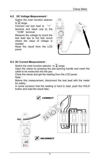
6-2 DC Voltage Measurement:
Switch the main function selector to range. Connect red test lead to “+"terminal and black one to the “COM"terminal. Measure the voltage by touch the test lead tips to the test circuit where the value of voltage is needed. Read the result from the LCD panel.
6-3 AC Current Measurement:
Switch the main function selector to range. Open the clamp by pressing the jaw-opening handle and insert the cable to be measured into the jaw. Close the clamp and get the reading from the LCD panel. Note: Before this measurement, disconnect the test lead with the meter for safety. In some occasion that the reading is hard to read, push the HOLD button and read the result later.
CORRECT
INCORRECT
I600V
CAT I I
V
AC/DC CLAMP METER
A
A
V
600 600
Clamp Meter
8
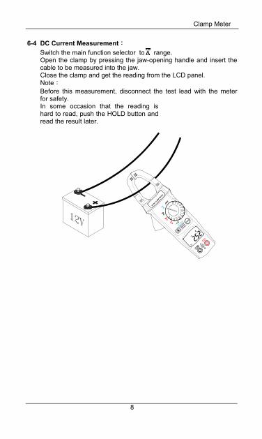
6-4 DC Current Measurement:
Switch the main function selector to range. Open the clamp by pressing the jaw-opening handle and insert the cable to be measured into the jaw. Close the clamp and get the reading from the LCD panel. Note: Before this measurement, disconnect the test lead with the meter for safety. In some occasion that the reading is hard to read, push the HOLD button and read the result later.
I
CAT I
600VI
VV
AAC/DC CLA
MPMETER
600
600
A
Clamp Meter
9
I600V
CAT I I
AC/DC CLAMP METER
V
V
A
A
600 600
I600V
CAT I I
AC/DC CLAMP METER
V
V
A
A
600 600
I600V
CAT I I
AC/DC CLAMP METER
V
V
A
A
600 600
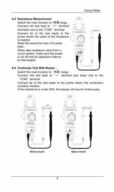
6-5 Resistance Measurement
Switch the main function to range. Connect red test lead to “+"terminal and black one to the "COM"terminal. Connect tip of the test leads to the points where the value of the resistance is needed. Read the result from the LCD panel. Note: When take resistance value from a circuit system, make sure the power is cut off and all capacitors need to be discharged.
6-6 Continuity Test With Buzzer:
Switch the main function to range. Connect red test lead to “ + " terminal and black one to the “COM"terminal. Connect tip of the test leads to the points where the conduction condition needed. If the resistance is under 40Ω, the beeper will sound continuously.
Short circuit Open circuit
Clamp Meter
10
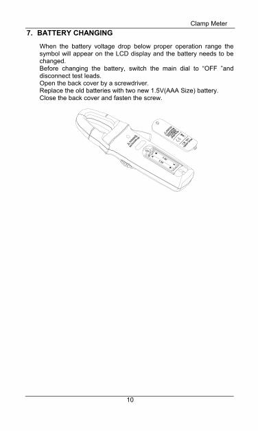
7. BATTERY CHANGING
When the battery voltage drop below proper operation range the symbol will appear on the LCD display and the battery needs to be changed. Before changing the battery, switch the main dial to “OFF ”and disconnect test leads. Open the back cover by a screwdriver. Replace the old batteries with two new 1.5V(AAA Size) battery. Close the back cover and fasten the screw.
Clamp Meter
11
8. MAINTENANCE
WARNING!
Before open the meter, disconnect both test lead and never uses the meter before the cover is closed.
CAUTION! To avoid contamination or static damage, do not touch the circuit board without proper static protection.
8-1 REMARK:
If the meter is not going to be used for a long time, take out the battery and do not store the meter in high temperature or high humidity environment.
When take current measurement, keep the cable at the center of the clamp will get more accurate test result.
Repairs or servicing not covered in this manual should be performed only by qualified personal.
8-2 CLEANING:
Periodically wipe the case with a dry cloth. Do not use abrasives or solvents on these instruments.

MEMO:

MEMO:

CENTER TECHNOLOGY CORP. 4 / F NO. 415, Jung-Jeng Rd., 238 Shu-Lin, Taipei, Taiwan
TEL : 886-2-26763926 E-Mail : [email protected] FAX : 886-2-26763925 http : / / www.centertek.com
GCA000252-02000