Embed Size (px)
Citation preview
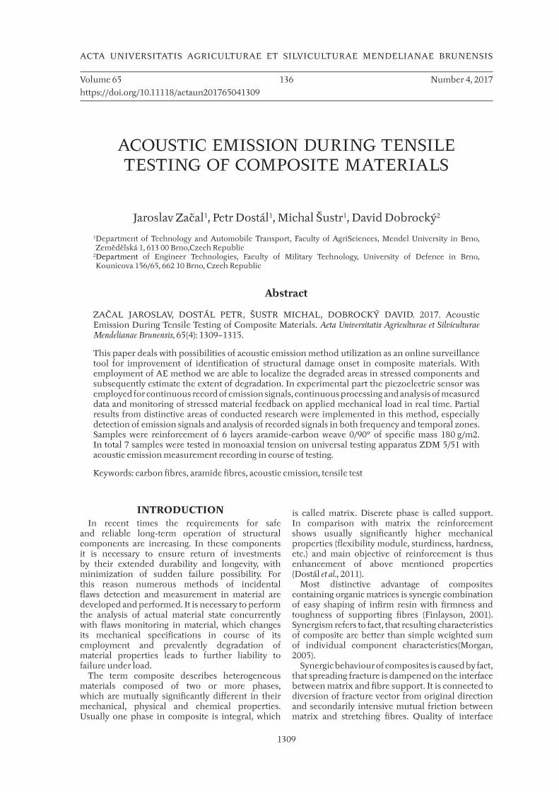
1309
ACTA UNIVERSITATIS AGRICULTURAE ET SILVICULTURAE MENDELIANAE BRUNENSIS
Volume 65 136 Number 4, 2017
https://doi.org/10.11118/actaun201765041309
ACOUSTIC EMISSION DURING TENSILE TESTING OF COMPOSITE MATERIALS
Jaroslav Začal1, Petr Dostál1, Michal Šustr1, David Dobrocký2
1 Department of Technology and Automobile Transport, Faculty of AgriSciences, Mendel University in Brno, Zemědělská 1, 613 00 Brno,Czech Republic
2 Department of Engineer Technologies, Faculty of Military Technology, University of Defence in Brno, Kounicova 156/65, 662 10 Brno, Czech Republic
Abstract
ZAČAL JAROSLAV, DOSTÁL PETR, ŠUSTR MICHAL, DOBROCKÝ DAVID. 2017. Acoustic Emission During Tensile Testing of Composite Materials. Acta Universitatis Agriculturae et Silviculturae Mendelianae Brunensis, 65(4): 1309–1315.
This paper deals with possibilities of acoustic emission method utilization as an online surveillance tool for improvement of identification of structural damage onset in composite materials. With employment of AE method we are able to localize the degraded areas in stressed components and subsequently estimate the extent of degradation. In experimental part the piezoelectric sensor was employed for continuous record of emission signals, continuous processing and analysis of measured data and monitoring of stressed material feedback on applied mechanical load in real time. Partial results from distinctive areas of conducted research were implemented in this method, especially detection of emission signals and analysis of recorded signals in both frequency and temporal zones. Samples were reinforcement of 6 layers aramide-carbon weave 0/90° of specific mass 180 g/m2. In total 7 samples were tested in monoaxial tension on universal testing apparatus ZDM 5/51 with acoustic emission measurement recording in course of testing.
Keywords: carbon fibres, aramide fibres, acoustic emission, tensile test
INTRODUCTIONIn recent times the requirements for safe
and reliable long-term operation of structural components are increasing. In these components it is necessary to ensure return of investments by their extended durability and longevity, with minimization of sudden failure possibility. For this reason numerous methods of incidental flaws detection and measurement in material are developed and performed. It is necessary to perform the analysis of actual material state concurrently with flaws monitoring in material, which changes its mechanical specifications in course of its employment and prevalently degradation of material properties leads to further liability to failure under load.
The term composite describes heterogeneous materials composed of two or more phases, which are mutually significantly different in their mechanical, physical and chemical properties. Usually one phase in composite is integral, which
is called matrix. Discrete phase is called support. In comparison with matrix the reinforcement shows usually significantly higher mechanical properties (flexibility module, sturdiness, hardness, etc.) and main objective of reinforcement is thus enhancement of above mentioned properties (Dostál et al., 2011).
Most distinctive advantage of composites containing organic matrices is synergic combination of easy shaping of infirm resin with firmness and toughness of supporting fibres (Finlayson, 2001).Synergism refers to fact, that resulting characteristics of composite are better than simple weighted sum of individual component characteristics(Morgan, 2005).
Synergic behaviour of composites is caused by fact, that spreading fracture is dampened on the interface between matrix and fibre support. It is connected to diversion of fracture vector from original direction and secondarily intensive mutual friction between matrix and stretching fibres. Quality of interface
1310 Jaroslav Začal, Petr Dostál, Michal Šustr, David Dobrocký
between matrix and support therefore has a crucial influence on characteristics of resulting composite. Composites are arranged and manufactured in a way to maximize the synergic effect (Grosse, 2008).
Acoustic emission method (AE) is based on physical background of measurement of elastic tension wave spreading through object material or on its surface. These tension waves are generated with occurrence of plastic deformations in material exposed to external forces (mechanical stress)(Miller et al., 2005).To estimate the dampening magnitude in practice, the testing of basic calibration source of AE emission is commonly used, denoted as Pen Test(Scruby, 1987). This form of testing represents the sudden quantum alleviation of force affecting the surface of object in perpendicular direction, which results to occurrence of sharp pulse (Dobrocký et al., 2016). Pen Test is employed in measurement of dampening and velocity of wave spread in given material, and also to calibrate the AE sensors, eventually for expression of the AE sources intensity in ratio to Pen Test (Yoon et al., 1995).Entire process of AE emission and detection encompasses several phases: the event of acoustic emission, spreading of tensile waves from source to sensor, detection of tensile waves with sensor and transformation to electric signal and finally estimation of resulting electric AE signal with measuring equipment (Dickinson, 1990).
MATERIALS AND METHODSFor tested set of samples the dimension and shape
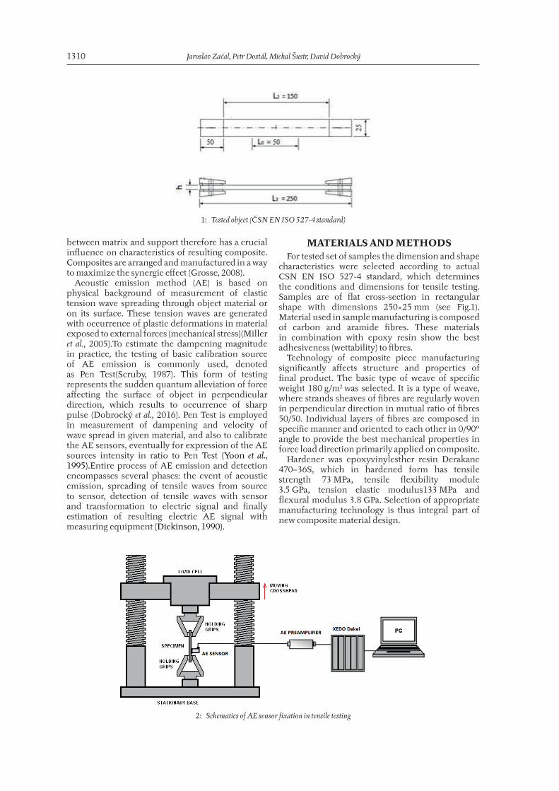
characteristics were selected according to actual CSN EN ISO 527-4 standard, which determines the conditions and dimensions for tensile testing. Samples are of flat cross-section in rectangular shape with dimensions 250×25 mm (see Fig.1). Material used in sample manufacturing is composed of carbon and aramide fibres. These materials in combination with epoxy resin show the best adhesiveness (wettability) to fibres.
Technology of composite piece manufacturing significantly affects structure and properties of final product. The basic type of weave of specific weight 180 g/m2 was selected. It is a type of weave, where strands sheaves of fibres are regularly woven in perpendicular direction in mutual ratio of fibres 50/50. Individual layers of fibres are composed in specific manner and oriented to each other in 0/90° angle to provide the best mechanical properties in force load direction primarily applied on composite.
Hardener was epoxyvinylesther resin Derakane 470–36S, which in hardened form has tensile strength 73 MPa, tensile flexibility module 3.5 GPa, tension elastic modulus133 MPa and flexural modulus 3.8 GPa. Selection of appropriate manufacturing technology is thus integral part of new composite material design.
1: Tested object (ČSN EN ISO 527-4 standard)
2: Schematics of AE sensor fixation in tensile testing
Acoustic Emission During Tensile Testing of Composite Materials 1311
Essence of testing accordingto CSN EN ISO 527-4:
• mean of tensile load transfer to tested object is in shear with terminal fi ttings
• it is conducted as burdening of tested object placed in testing apparatus with axial force eff ecting the object
• test provides information on quality of binding between resin and fi bresFor tensile testing of model composite sample
the universal testing machine ZDM 5/51 was employed. Measured sample dimensions were 250×25×1 mm (length × width × thickness) and samples were fi xed in self-locking jaws and loaded with jaws dilation at 5 mm/min (Fig. 2). From previously conducted experiment this velocity was determined optimal for AE recording.
AE signals were detected in course of tensile testing with one piezoelectric sensor Dakel fi xed in upper part of samples with clamp. Contact surface
of the sensor was lightly greased with ultrasonic gel. Measurement of acoustic emission was conducted with use of Dakel XEDO apparatus. Confi guration of measuring equipment is described in (Tab. I).
Root mean square (RMS) parameter of AE signal was observed. This parameter denotes so called signal eff ective value. With alternating current / intensity is RMS equal to direct current / intensity, which aft er application of resistance load would report same mean power. Unit of RMS is mV. This value informs of the quantitative characteristics of measured AE events (amount of released energy).
RESULTS AND DISCUSSIONMonitoring of composite material tensile testing
was conducting be means of AE measurement. Essential factor in experiments is calibration of measuring apparatus sensitivity. In course of signal recording its intensity shift s signifi cantly and it is
I: XEDO measuring apparatus confi guration
AE parameter Value
Sampling frequency 2 MHz
Gain (sensor) 30 dB
Gain (pre-amp) 20 dB
Voltage range ± 2000 mV
Period 1000 ms
Start event 600 ppt range
end of the event 600 ppt range
dead time 992 microseconds
minimum 100 microseconds
0
2000
4000
6000
8000
10000
12000
14000
16000
18000
20000
0 20 40 60 80 100 120 140 160
F [
N]
t [s]
Tensile results
Sample 1 Sample 2 Sample 3 Sample 4 Sample 5 Sample 6 Sample 7
3: Tensile test results
1312 Jaroslav Začal, Petr Dostál, Michal Šustr, David Dobrocký
necessary to calibrate setting covering the widest range of emitted signals. This results in protection from excessive dampening, or contrary from overflow from the measuring range.
Obtained results show that AE measurement method is appropriate for discovery of initial structural changes in material. Individual stages of composite material disturbance were detected (changes in mechanical properties, separation of fibres from matrix, stretching of fibres from matrix, tearing of fibres, delamination).
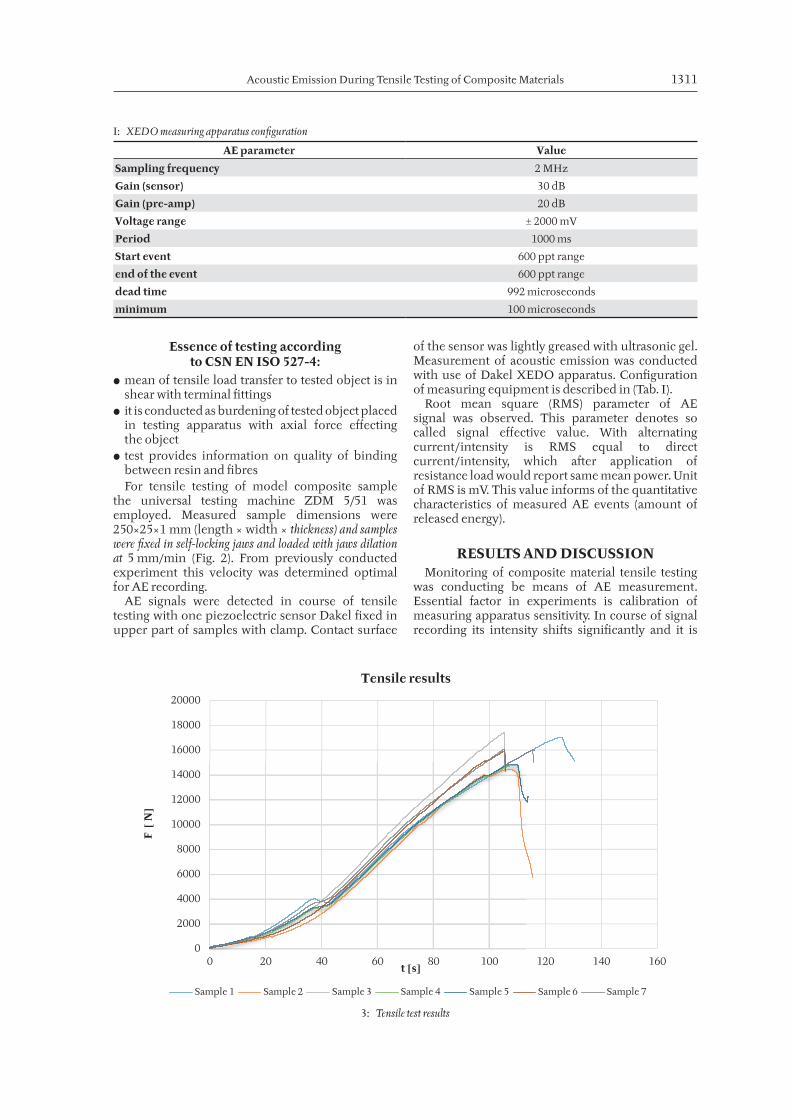
In comparison of sample in tensile testing, it is obvious that results show same variability. Fig. 3provides the overview of data recorded in measurement of aramide-carbon tensile strength thresholds. Individual curves suggest that endpoints of tested samples show relatively small indentation from fixing clamps. Curves of composite samples report considerably steep characteristics and report no typical signature of soft material. From mentioned characteristics, it is obvious that hit length is a viable characteristic of degradation progress namely in cases where the material or its vicinity is accessible for measurement.
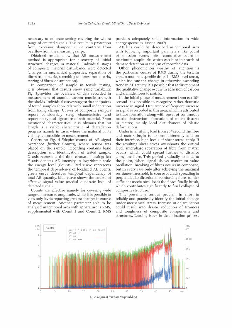
Charts on Fig. 4–5depict counts of AE signal overshoot (further Counts), where sensor was placed on the sample. Recording contains basic description and identification of tested sample. X axis represents the time course of testing; left Y axis denotes AE intensity in logarithmic scale the energy level (Counts). Red curve represents the temporal dependency of localized AE events, green curve describes temporal dependency of total AE quantity, blue curve shows the course of effective signal value (medial quadratic level of detected signal).
Counts are effective namely for covering wide range of measured amplitude, whilst it is possible to view only levels reporting greatest changes in course of measurement. Another parameter able to be analysed in temporal area with apparature is RMS, supplemented with Count 1 and Count 2. RMS
provides adequately stable information in wide energy spectrum (Fasana, 2007).
AE hits could be described in temporal area with following important parameters like count of emission events (hits), cumulative count or maximum amplitude, which can hint in search of damage detection in analysis of recorded data.
Other phenomenon worthy of attention is the particular course of RMS during the test. In certain moment, specific drops in RMS level occur, which indicate the change in otherwise ascending trend in AE activity. It is possible that at this moment the qualitative change occurs in adhesion of carbon and aramide fibres to matrix.
In the initial phase of measurement from cca 10th second it is possible to recognize rather dramatic increase in signal. Occurrence of frequent increase in signal is recorded in this area, which is attributed to trace formation along with onset of continuous matrix destruction –formation of micro fissures in matrix; mainly local disturbances of plastic deformations.
Under intensifying load from 25th second the fibre and matrix begin to deform differently and on their interface, high levels of shear stress apply. If the resulting shear stress overshoots the critical level, interphase separation of fibre from matrix occurs, which could spread further to distance along the fibre. This period gradually extends to the point, when signal shows maximum value oscillation. Breaking of fibres occurs in composite, but in every case only after achieving the maximal resistance threshold. In course of crack spreading in perpendicular direction to reinforcing fibres (under sufficient mechanical load) the fibres finally break, which contributes significantly to final collapse of composite structure.
This presents a serious problem in effort to reliably and practically identify the initial damage under mechanical stress. Increase in delamination could result into drastic reduction of firmness and toughness of composite components and structures. Leading force in delamination process
sec0 5 10 15 20 25 30 35 40 45
cntlog
0
1
2
3
4
5
0
RMSmV
0
200
400
600
800
1000
0
X0~19.8.2015 11:01:30.22714317.01.c117.01.c217.01.rms
Counts4
4: Analysis of resulting temporal data
Acoustic Emission During Tensile Testing of Composite Materials 1313
is disproportion between elastic constants between neighbouring layers, which results into onset of high interlaminar tension. Occurrence of delamination is every time associated with absorption of high amount of fracture energy.
Chart depicts relatively regular decrease in AE signal in all samples, which occurs in certain interval (approx. 24 sec.). Therefore, it was concluded, that it isn’t caused by mechanical influence of measuring apparatus, i. e. deformation of sample edges in jaws in course of force load increase.
In mechanical loading of composites the extensive damage in entire sample appears. Among these structural malfunctions, we can namely introduce plastic deformation of matrix, occurrence of micro fissures in matrix, separation of fibre from matrix, stretching the fibres from matrix, damage of support (breaking of fibres) and separation of individual layers (delamination).
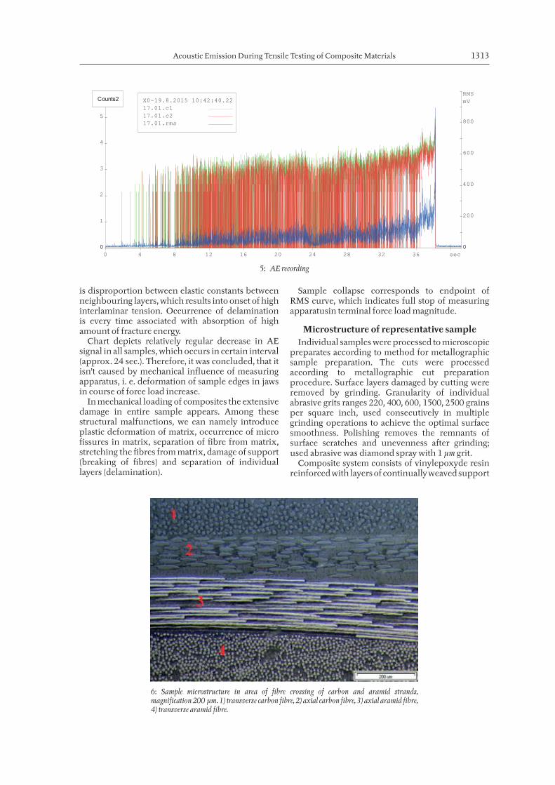
Sample collapse corresponds to endpoint of RMS curve, which indicates full stop of measuring apparatusin terminal force load magnitude.
Microstructure of representative sampleIndividual samples were processed to microscopic
preparates according to method for metallographic sample preparation. The cuts were processed according to metallographic cut preparation procedure. Surface layers damaged by cutting were removed by grinding. Granularity of individual abrasive grits ranges 220, 400, 600, 1500, 2500 grains per square inch, used consecutively in multiple grinding operations to achieve the optimal surface smoothness. Polishing removes the remnants of surface scratches and unevenness after grinding; used abrasive was diamond spray with 1 µm grit.
Composite system consists of vinylepoxyde resin reinforced with layers of continually weaved support
sec0 4 8 12 16 20 24 28 32 36
cntlog
0
1
2
3
4
5
0
RMSmV
0
200
400
600
800
0
X0~19.8.2015 10:42:40.22714317.01.c117.01.c217.01.rms
Counts2
5: AE recording
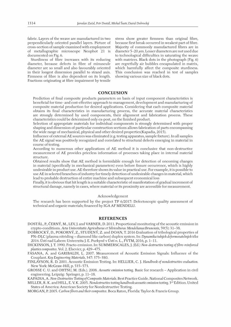
6: Sample microstructure in area of fibre crossing of carbon and aramid strands, magnification 200 µm. 1) transverse carbon fibre, 2) axial carbon fibre, 3) axial aramid fibre, 4) transverse aramid fibre.
1314 Jaroslav Začal, Petr Dostál, Michal Šustr, David Dobrocký
fabric. Layers of the weave are manufactured in two perpendicularly oriented parallel layers. Picture of cross-section of sample examined with employment of metallographic microscope Neophot 21 is documented on Fig. 6.
Sturdiness of fibre increases with its reducing diameter, because defects in fibre of minuscule diameter are so small and also favourably oriented in their longest dimension parallel to strand axis. Firmness of fibre is also dependent on its length. Fractions originating at fibre impairment by tensile
stress show greater firmness than original fibre, because first break occurred in weakest part of fibre. Majority of commonly manufactured fibres are in diameter 5–20 µm. Lesser diameters are not used due to technological difficulties in saturating the weave with matrices. Black dots in the photograph (Fig. 6) are regretfully air bubbles encapsulated in matrix, which harmfully affect the composite sturdiness. This conclusion was reached in test of samples showing various size of black dots.
CONCLUSIONPrediction of final composite products parameters on basis of input component characteristics is beneficial for time- and cost-effective approach to management, development and manufacturing of composite material production for desired applications. Considering that each composite material obtains its final characteristics in manufacturing process, the accurate material characteristics are strongly determined by used components, their alignment and fabrication process. These characteristics could be determined only ex-post, on the finished product.Selection of appropriate materials for individual components is strongly determined with proper shaping and dimension of particular construction sections allows fabrication of parts encompassing the wide range of mechanical, physical and other desired properties(Kapadia, 2015).Influence of external AE sources was eliminated (e.g. testing apparatus, sample fixture). In all samples the AE signal was positively recognized and correlated to structural defects emerging in material in course of testing.According to numerous other applications of AE method it is conclusive that non-destructive measurement of AE provides priceless information of processes taking place in internal material structure.Obtained results show that AE method is formidable enough for detection of oncoming changes in material (specifically in mechanical parameters) even before fissure occurrence, which is highly undesirable in product use. AE therefore shows its value in practical use. For example, it is possible to use AE in selected branches of industry for timely detection of undesirable changes in material, which lead to probable destruction of entire machine and subsequent economical lossFinally, it is obvious that hit length is a suitable characteristic of manifestation of gradual increment of structural damage, namely in cases, where material or its proximity are accessible for measurement.
Acknowledgement
The research has been supported by the project TP 6/2017: Defectoscopic quality assessment of technical and organic materials; financed by IGA AF MENDELU.
REFERENCESDOSTÁL, P., ČERNÝ, M., LEV, J. and VARNER, D. 2011. Proportional monitoring of the acoustic emission in
crypto-conditions. Acta Universitatis Agriculturae et Silviculturae MendelianaeBrunensis, 59(5): 31–38.DOBROCKÝ, D., POKORNÝ, Z., STUDENÝ, Z. and DOAN, T. 2016 Evaluation of tribological properties of
PN+DLC (plasma nitriding + diamond like carbon) duplex system. In: Dynamika tuhých deformovatelných těles 2016. Ústí nad Labem: Univerzita J. E. Purkyně v Ústí n. L., FVTM, 2016, p. 1–11.
DICKINSON, J. T. 1990. Fracto-emission. In: SUMMERSCALES, J. (Ed.) Non-destructive testing of fibre-reinforced plastics composites. Vol. 2. Elsevier, p. 429–475.
FASANA, A. and GARIBALDI, L. 2007. Measurement of Acoustic Emission Signals: Influence of the Couplant. Key Engineering Materials, 347: 375–380.
FINLAYSON, R. D. 2001. Acoustic Emission Testing. In: HELLIER, C. J. Handbook of nondestructive evaluation. New York: McGraw-Hill, p. 535–573.
GROSSE C. U. and OHTSU, M. (Eds.). 2008. Acoustic emission testing. Basic for research – Application in civil engineering. Leipzig: Springer, p. 11–18.
KAPADIA, A. Non-Destructive Testing of Composite Materials. Best Practice Guide. National Composites Network.MILLER, R. K. and HILL, E. V. K. 2005. Nondestructive testing handbook:acoustic emission testing. 3rd Edition. United
States of America: American Society for Nondestructive Testing.MORGAN, P. 2005. Carbon fibers and their composites. Boca Raton, Florida: Taylor & Francis Group.

Acoustic Emission During Tensile Testing of Composite Materials 1315
SCRUBY, C. B. 1987. Instrument Science and Technology. An Introduction to Acoustic Emission. Journal of Physics E, Scientific Instruments, 20(8): 946–953.
ÚNMZ. 1998. Plastics - Determination of tensile properties – Part 4: Test conditions for isotropic and orthotropic fiber-reinforced plastic composites. ČSN EN ISO 527–4. Prague: The Office for Standards, Metrology and Testing.
YOON, D. J., KWON, O. Y., CHUNG, M. H. and KIM, M. H. 1995. Early Detection of Damages in Journal Bearings by Acoustic Emission Monitoring. Journal of acoustic emission, 13: 1–10.
Contact information
Jaroslav Začal: [email protected] Dostál: [email protected] Šustr: [email protected] Dobrocký:[email protected]