Embed Size (px)
Citation preview

Active Wearable Vision Sensor:Recognition of Human Activities and Environments
Kazuhiko Sumi††Graduate School of Informatics
Kyoto UniversityKyoto 606-8501, Japan
Akihiro Sugimoto‡
‡National Institute ofInformatics
Tokyo 101-8430, [email protected]
Takashi Matsuyama†
Masato Toda†
[email protected] Tsukizawa†
Abstract
To realize a symbiotic relationship between humans andcomputers, it is crucial to estimate the external and internalstate of the human by observation. One promising approachis to acquire the same visual information as the human ac-quires. In this paper, we introduce our wearable vision sen-sor, which is equipped with a pair of active stereo camerasand a gaze-direction detector. From the visual informationobtained by the wearable vision sensor, we present three ba-sic three functionalities: a 3D gaze point detection and im-age retrieval, a 3D digitization of a hand-held object, andthe measurement of a walking trajectory.
1. Introduction
Recently, human-machine symbiotic systems have beenstudied extensively. Their most important characteristic isan ability to interact with a human without manual invoca-tion, conventional cooperative systems must wait for an in-vocation event to start interaction. Instead of waiting for anevent, a symbiotic system observes the human physical stateand estimates such emotional states as interest, intention,sympathy and feeling. Based on the estimation, a symbioticsystem will start to interact with a human as well as syn-chronize itself with human action. Vision is a crucial tool toobserve a human as well as his environment.
There are two approaches to human observation. One isthe embedded ubiquitous vision in our environment, and theother is to wear vision. Although, recent progress in elec-tronics has enhanced the feasibility of ubiquitous embeddedvision, we believe that wearable vision is superior to the en-vironmental vision, because it shares a similar sight with
the human wearing it. Since, environmental vision does nothave manipulation capability, it is only able to observe hu-man action from a viewpoint different than the human. Onthe other hand, wearable vision, which combines sensorymotion with human vision, can share and experience almostexactly the same sight as humans. In addition to the realiza-tion of symbiotic systems, analyzing the sight of the wear-able vision sensor will foster the study of humans. So, wehave developed a wearable vision sensor[15].
One advance of the wearable vision sensor is that it cor-responds to human sight. Human vision has both a very pre-cise resolution at its center and a very wide field of view. Inhuman vision, eyeball moves from point to point accordingto the interest of the human. To emulate human sight, ourwearable vision sensor is equipped with a gaze-direction de-tector and a pair of active stereo cameras that have pan, tiltand zoom control features. We have researched the follow-ing three basic functionalities of the wearable vision sensor.One is to detect the three dimensional gaze point of humansand retrieve the image of interest. The second is to digi-tize the object shape and texture in 3D while it is manipu-lated by hand. The last is to recover the trajectory of humanmovement. In the following section, we present those func-tionalities one by one and conclude with directions for fu-ture research.
2. 3D gaze point detection and image retrieval
In this section, we present a method to retrieve the im-age of the object of interest, by 3D gaze point detection andcamera control.
Wearable vision has been researched in various ways[7, 5, 10, 17]. The biggest advantage of wearable vision isthat it shares its field of sight with the human who wears

it. However, balancing a wide field of view and resolutionis a problem that must be solved. This research proposes tosolve this problem by using gaze-direction and active cam-eras. It is also quite natural that a person’s field of visionstrongly reflects his/her interest or attention regardless ofhis/her consciousness [4].
RightCamera
EyeCamera
LeftCamera
Figure 1. Appearance of active wearable vi-sion sensor
A human’s viewing line can be measured by a device,called a NAC Corporation EMR-8, that projects an infra-red light beam onto an eye and detects its reflection from theretina (through the iris) and the cornea with an eye-directionsensor camera. Since the retinal and the cornea reflectionsreside on different spheres of the eye, the direction of theeye can be computed from those two reflections. Our wear-able vision sensor, shown in Figure 1, uses this device tomeasure the gaze-direction. The sensor is equipped with apair of SONY EVI-G20 active stereo cameras. Each of thecamera is equipped with pan, tilt, and zoom mechanism,that are controlled by a computer. The camera is located onthe side of the head. Those three devices are mounted onan bracket around a helmet to fix the geometrical relation-ship between the stereo camera and the gaze-direction de-tector. Their geometrical configuration is calibrated with themethod shown in [15]. This configuration enables the sen-sor to share the same sight as the human.
In our proposed wearable vision sensor, the first problemis controlling the active cameras so that they share the samesight as the human who wears the sensor. The vision sensorshould have the following capabilities:
• To acquire images from a wide field of view, if the hu-man does not fix the sight.
• To track the human’s gaze.
• To acquire images with high resolution, when the hu-man fixes his sight on an object.
Since a wide field of view and a view with high resolutionare mutually exclusive, we have developed a control algo-rithm based on gaze direction. To detect fixation of sight,temporal average of gaze direction is calculated. If the aver-aged gaze direction is fixed, the camera is zoomed up, but ifit is changing, the camera is zoomed down. We have also de-veloped a fast viewing-depth estimation algorithm that usesstereo cameras and a gaze-direction detector. In the follow-ing subsection, we will describe the detailed system and itsalgorithms.
2.1. Estimation of 3D gaze point
The 3D gaze-point is defined as the intersection of aviewing line and the viewed object. In Figure 2, camerasand the gaze-direction detector have been calibrated in ad-vance. The viewing line is projected onto the screen of eachcamera. It is equivalent to the epipolar line of a viewing line.In the pair of stereo images in Figure 2, from the closestpoint to infinity on the viewing line, we assume the depth,and then crop the corresponding sub-image from the im-age on each screen. Those two images will match aroundthe gaze point. Using this epipolar constraint, the numberof trials required to calculate the best match is 10 to 100times reduced, compared with standard stereo matching.
According to the 3D gaze-point measurement, we con-trol the pan, tilt, and zoom parameters of the active cameraas follows:
• If the gaze point is moving, the camera is zoomed outto retrieve a wide viewing field. Pan and tilt are con-trolled to follow the gaze direction.
• If the gaze point is fixed, the camera is zoomed in toretrieve a detailed image of the gazed object. The panand tilt are controlled to converge toward the 3D gazepoint.
We have implemented the above strategy with a dynamicmemory architecture[13], whose control schematic diagramis shown in Figure 3. An example of the advantage of thissystem is shown in Figure 4. In Figure 4, both the left andright images are shown in the upper and lower rows, respec-tively. Each image is superimposed on the epipolar line witha white line, to represent the gaze direction. A yellow dot ismarked on the 3D gaze point. The left image is taken with-out camera control, while the right image is taken with cam-era pan, tilt and zoom control. Based on the vantage point ofthe camera control, the gazed object (a computer box) canbe observed in detail.
We have proposed a wearable vision sensor with a gaze-direction detector and a pair of stereo cameras. We showedthat the 3D gaze point is quickly detected by finding the bestimage match along the epipolar line derived from gaze di-rection. Adding 3D gaze location to the camera control, we

Gazing Point
Left Image
Right Eye
Left Camera Right Camera
Right Image
ViewingLine
Left Image Right Image
matching
mis-matching
Figure 2. Optical configuration of wearablevision sensor and principal 3D gaze-point de-tection
Active Wearable Vision Sensor
Gaze Direction Recorder
Gaze Direction
Stereo Images
Camera Control Command
Gaze Point Detection System
3D Gaze Point Calculation
Gaze StateRecognition
Camera ControlCalculation
OUTPUT
Images of the Gazing Object
3D Gaze Point
Gaze Condition
Stereo Cameras
Figure 3. Control scheme of 3D gaze point de-tection and camera control
a left image a left image
without gaze control with gaze control
a right image a right image
without gaze control with gaze control
Figure 4. Results of 3D Gaze point detectionand camera control
can resolve the exclusive difficulty for the viewing field andimage resolution. Our future work will extend this proposalto include 3D object extraction.
3. 3D Digitization of a hand-held object
The second aspect of our research into the wearable vi-sion sensor is the digitization of a hand-held object in 3D.A symbiotic system must recognize the action and feelingof the human living together. If the object of action is smallenough, it can typically be held and manipulated by hand.Ideally, the object should be recognized while it is in hishand. The human feeling to the object in hand should alsobe recognized.
Most of the research into observation, based on hand-held manipulation of objects, has concentrated on the hand-object relationship[14][6]. But hand-object-view relation-ships have not been not studied yet. Our biggest concernis the kind of view that can be acquired from the recogni-tion of the object and the intention of the human manipulat-ing it. Introducing the idea of “view” into hand-object rela-tionships opens a new possibility for estimating human feel-ings, such as interest and intention, to the object in his hand.Therefore, our next research target will be 3D-shape extrac-tion – both of the object and of the hand. In this paper, weseparate the hand-object-view relationship into four typicalcases and analyze what kind of visual information can beacquired from them.

There have been two major approaches to reconstructthe 3D shape. One is to use multiple synchronous imagestaken by multiple cameras [12]. The other is to use multipleasynchronous images taken along a time sequence. The syn-chronous approach can deal with dynamic scenes. However,the asynchronous approach assumes a static scene, in whichnothing changes along the time sequence, so the images areequivalent to the synchronous approach. Once connected tothe synchronous model, we can apply such well studied 3Dreconstruction methods as the factorization method [16],volume intersection [1] [2], and space carving [11]. How-ever, a hand-manipulated object is obscured by the hands.During manipulation, each hand changes its shape and loca-tion relative to the object dynamically, so it is not capturedby the asynchronous single camera approach. Although, asynchronous approach can solve this problem, it is not suit-able for our wearable vision. 3D shape extraction of thehand-held object by a wearable vision sensor presents a newvision problem.
In this research, 3D shape extraction of a hand-held ob-ject is regarded as a new class of shape extraction prob-lem because of the asynchronous images which are capturedwhen a dynamic occluding object exists.
Our approach is based on vacant space, which is definedas space that is certain to be vacant. It can be derived bothfrom silhouettes and from stereo matching. Since the handis a dynamic object occluding the static object, the vacantspace will change from image to image and extend its spaceuntil it reaches the boundaries of the static object. Finally,we can get the 3D shape of the static object without the dy-namic occlusive object. This paper proposes the following:
1. From the observation viewpoint, we analyzed humanmanipulation into four types: shape acquisition, vi-sual texture acquisition, haptic texture acquisition, andtotal-appearance acquisition. We classified the rela-tionships between the manipulation type and the visualinformation that we obtained.
2. We propose a dynamic space carving for 3D shape ex-traction of a static object occluded by a dynamic ob-ject moving around the static object. We showed thatby using vacant space, the dynamic object will be elim-inated along the carving.
3. We showed that the integration in vacant space of astereo-depth map and a silhouette improves the effi-ciency of dynamic space carving.
3.1. Hand-Object-View Relationships
When a person takes an object in his hands and observesit, it is not possible to acquire all of its information simul-taneously. When the object is manipulated by hand, its visi-ble part changes depending on how it is held or the physical
relationship between the object and the hand. We classifyhand-object-view relationships into four classes accordingto the information which the holder of the object can ac-quire.
(a) Shape Acquisition (b) Visual Texture Acquisi-tion
(c) Haptic Texture Acquisi-tion
(d) Total Appearance Ac-quisition
Figure 5. Hand-object-view relationships
Shape Acquisition : The object obscures much of thehand, so its silhouette is visible. Figure 5(a),
Visual Texture Acquisition : The object is in front of thehand, so its texture is visible. Figure 5(b).
Haptic Texture Acquisition : The object is wrapped bythe hands. Even though the object can be observed, lit-tle visual information can be acquired. Figure 5(c).
Total Appearance Acquisition : The object is turned bythe hand, so that a total view, both of shape and tex-ture, is acquired. Figure 5(d).
Since it is difficult for a computer to distinguish the cap-tured image in the above examples, we propose to use bothshape and texture for 3D shape extraction, and integratethem in our proposed vacant space.
3.2. Vacant Space
It is not always easy to distinguish between an object anda hand, especially if the object is being held in the hand.Therefore, the object and the hand are observed as one ob-ject, whose shape is changing in time. This makes it diffi-cult to apply such conventional techniques as shape from
silhouettes [9] and space carving [11] because they dependon the correspondence of the texture on the stable object. In-stead, we propose to detect vacant space, defined as spacewhich is certain not to be occupied by any object. If va-cant space is carved, the space occupied by a hand will in-tersect with the moving hand. The intersection will becomezero if the hand moves in a sufficiently large area. On theother hand, since the object does not change, the object’sspace will never become vacant space. Therefore, if vacantspace is carved using a long image sequence, only the ob-ject remains in space.
3.3. Processing Procedure
Based on vacant space detection, the 3D object extrac-tion is implemented as follows:
1. Capture – A series of stereo images are captured bythe wearable vision sensor.
2. Camera Motion Recovery – First, feature points aredetected by a Harris Corner Detector [8]. The 3D loca-tion of the feature points are calculated by stereo anal-ysis for each image. Next, the camera position is esti-mated by an advanced ICP algorithm [3].
3. Depth Map Acquisition – For each viewpoint, a depthmap is computed by region based stereo analysis.
4. Silhouette Acquisition – For each viewpoint, a silhou-ette is computed by background subtraction.
5. Carving Vacant Space – The vacant space is updatedby the above silhouette and the depth map.
3.4. Evaluation
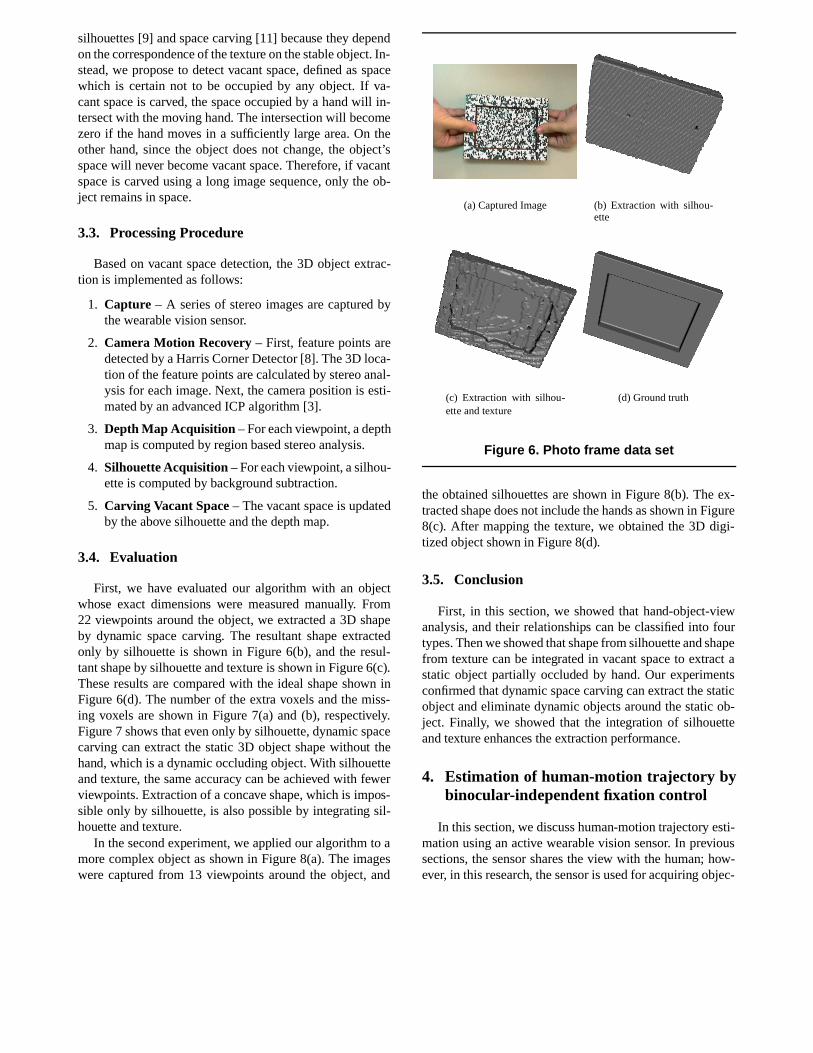
First, we have evaluated our algorithm with an objectwhose exact dimensions were measured manually. From22 viewpoints around the object, we extracted a 3D shapeby dynamic space carving. The resultant shape extractedonly by silhouette is shown in Figure 6(b), and the resul-tant shape by silhouette and texture is shown in Figure 6(c).These results are compared with the ideal shape shown inFigure 6(d). The number of the extra voxels and the miss-ing voxels are shown in Figure 7(a) and (b), respectively.Figure 7 shows that even only by silhouette, dynamic spacecarving can extract the static 3D object shape without thehand, which is a dynamic occluding object. With silhouetteand texture, the same accuracy can be achieved with fewerviewpoints. Extraction of a concave shape, which is impos-sible only by silhouette, is also possible by integrating sil-houette and texture.
In the second experiment, we applied our algorithm to amore complex object as shown in Figure 8(a). The imageswere captured from 13 viewpoints around the object, and
(a) Captured Image (b) Extraction with silhou-ette
(c) Extraction with silhou-ette and texture
(d) Ground truth
Figure 6. Photo frame data set
the obtained silhouettes are shown in Figure 8(b). The ex-tracted shape does not include the hands as shown in Figure8(c). After mapping the texture, we obtained the 3D digi-tized object shown in Figure 8(d).
3.5. Conclusion
First, in this section, we showed that hand-object-viewanalysis, and their relationships can be classified into fourtypes. Then we showed that shape from silhouette and shapefrom texture can be integrated in vacant space to extract astatic object partially occluded by hand. Our experimentsconfirmed that dynamic space carving can extract the staticobject and eliminate dynamic objects around the static ob-ject. Finally, we showed that the integration of silhouetteand texture enhances the extraction performance.
4. Estimation of human-motion trajectory bybinocular-independent fixation control
In this section, we discuss human-motion trajectory esti-mation using an active wearable vision sensor. In previoussections, the sensor shares the view with the human; how-ever, in this research, the sensor is used for acquiring objec-

(a) Extra Voxels
(b) Missing Voxels
Figure 7. Error analysis of dynamic spacecarving
tive information: the field of view from the cameras is inde-pendent of the person’s.
To estimate human-motion trajectory with two activewearable cameras, we introduce fixation control, i.e., cam-era control in which the camera automatically fixates its op-tical axis on a selected point (called the fixation point) in3D and applies fixation control independently to each ac-tive camera. That is, while the person moves, we control thetwo active cameras independently so that each camera au-tomatically fixates its optical axis to its own fixation point.We call this camera control the binocular-independent fixa-tion control (Figure 9).
In binocular-independent fixation control, the two cam-eras need not share a common field of view because eachcamera fixates its optical axis on its own fixation point in3D. We do not face the problem of feature correspondencesbetween the images captured by the two cameras. More-over, the estimation accuracy becomes independent of thebaseline of two cameras.
To derive sufficient constraints to estimate human mo-tion, we employ lines, which we refer to as focused lines,nearby the fixation point, because (i) we find many lines inan indoor scene, and (ii) we can easily and accurately detectlines with less computation by using the Hough transforma-tion, and (iii) we can easily establish line correspondences
(a) Captured Image (b) Silhouette Image
(c) 3Dshape
(d) 3D shapewith texture
Figure 8. Monster figure data set
over time-series frames due to their spatial extents. The con-straints derived from line correspondences depend only onthe rotation component of the human motion. We can thusdivide the human motion estimation into two steps: the ro-tation estimation and the translation estimation.
The first step is the rotation estimation of the camera mo-tion. We assume a correspondence of n focused lines overtwo time-series frames. Then, we have n + 3 unknowns (nis from the scale factors and 3 is from the rotation), whereaswe have 3n constraints in this case. Therefore, we can es-timate the rotation of the camera motion if we have morethan two focused lines of correspondences.
When we finish estimating the rotation of the cameramotion, translation are the only factors that need to besolved. The constraint derived from the fixation correspon-dence thus becomes homogeneously linear with respect tothe unknowns. Hence, we can obtain the translation of thecamera motion up to scale from two fixation correspon-dences with only linear computation.
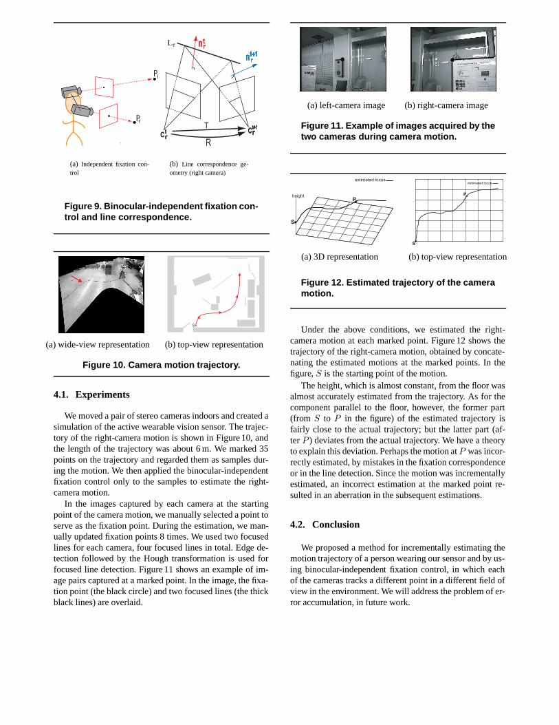
(a) Independent fixation con-trol
L
C
(b) Line correspondence ge-ometry (right camera)
Figure 9. Binocular-independent fixation con-trol and line correspondence.
(a) wide-view representation (b) top-view representation
Figure 10. Camera motion trajectory.
4.1. Experiments
We moved a pair of stereo cameras indoors and created asimulation of the active wearable vision sensor. The trajec-tory of the right-camera motion is shown in Figure 10, andthe length of the trajectory was about 6 m. We marked 35points on the trajectory and regarded them as samples dur-ing the motion. We then applied the binocular-independentfixation control only to the samples to estimate the right-camera motion.
In the images captured by each camera at the startingpoint of the camera motion, we manually selected a point toserve as the fixation point. During the estimation, we man-ually updated fixation points 8 times. We used two focusedlines for each camera, four focused lines in total. Edge de-tection followed by the Hough transformation is used forfocused line detection. Figure 11 shows an example of im-age pairs captured at a marked point. In the image, the fixa-tion point (the black circle) and two focused lines (the thickblack lines) are overlaid.
(a) left-camera image (b) right-camera image
Figure 11. Example of images acquired by thetwo cameras during camera motion.
(a) 3D representation (b) top-view representation
Figure 12. Estimated trajectory of the cameramotion.
Under the above conditions, we estimated the right-camera motion at each marked point. Figure 12 shows thetrajectory of the right-camera motion, obtained by concate-nating the estimated motions at the marked points. In thefigure, S is the starting point of the motion.
The height, which is almost constant, from the floor wasalmost accurately estimated from the trajectory. As for thecomponent parallel to the floor, however, the former part(from S to P in the figure) of the estimated trajectory isfairly close to the actual trajectory; but the latter part (af-ter P ) deviates from the actual trajectory. We have a theoryto explain this deviation. Perhaps the motion at P was incor-rectly estimated, by mistakes in the fixation correspondenceor in the line detection. Since the motion was incrementallyestimated, an incorrect estimation at the marked point re-sulted in an aberration in the subsequent estimations.
4.2. Conclusion
We proposed a method for incrementally estimating themotion trajectory of a person wearing our sensor and by us-ing binocular-independent fixation control, in which eachof the cameras tracks a different point in a different field ofview in the environment. We will address the problem of er-ror accumulation, in future work.

5. Summary
An active wearable vision sensor and its three importantfunctionalities are proposed in this paper. First, 3D gaze-point detection and image retrieval are proposed. They takeadvantage of the epipolar constraints given by the viewingdirection and the stereo cameras and the achieved real timecamera control which balances the viewing field and im-age resolution. Second, 3D digitization of a hand-held ob-ject is proposed. In this research, the hand-object relation-ship is classified by appearance variation. Then a new 3Dshape extraction algorithm, which we refer to as dynamic-space carving, is proposed. The 3D shape of a partially oc-cluded object is carved out of vacant space, which integratesboth silhouette and texture. Third, a new technique to keeptrack of multiple features in a stable environment is pro-posed to recover human-motion trajectory. The camera con-trol on a moving platform, which we refer to as binocular-independent fixation, is equivalent to the tracking of a mov-ing object from wide-baseline stereo cameras embedded inthe environment. This results in stable tracking and precisetrajectory estimation. Our future work will extend gaze andmanipulation analysis and focus on human observation andrecognition to help a symbiosis between machines and hu-mans in the near future.
Acknowledgements
Section 2 and Section 4 include work by AkihiroNakayama and Wataru Nagatomo for their master’s the-sis, respectively.
This series of research is supported in part by the In-formatics Research Center for Development of KnowledgeSociety Infrastructure, 21st. Century COE program and bycontracts 13224051 and 14380161 of the Ministry of Edu-cation, Culture, Sports, Science and Technology, Japan.
References
[1] H. Baker. Three-dimensional modeling. In Fifth int’l JointConf. on Artificial Intelligence, pages 649–655, 1977.
[2] B. G. Baumgart. Geometric modeling for computer vision.Stanford University Technical Report, AIM-249, 1974.
[3] P. J. Besl and N. D. McKey. A method for registration of 3-dshapes. IEEE Trans. PAMI, 14(2):239–256, 1992.
[4] R. Carpenter. Movements of the Eyes. Pion, London, 2ndedition, 1988.
[5] B. Clarkson, K. Mase, and A. Pentland. Recognizing user’scontext from wearable sensors: Baseline system. Visionand Modeling Technical Report, Media Lab. MIT, (TR-519),2000.
[6] M. R. Cutkosky. On grasp choice, grasp models, and the de-sign of hands for manufacturing tasks. IEEE Trans. Robot.Automat., 5(3):269–279, 1989.
[7] A. P. H. Aoki, B. Schiele. Realtime personal positioning sys-tem for wearable computers. Vision and Modeling TechnicalReport, Media Lab., MIT, (TR-520), 2000.
[8] C. J. Harris and M. Stephens. A combined corner and edgedetector. In 4th Alvey Vision Conf., pages 147–151, 1988.
[9] H. Hoppe, T. DeRose, T. Duchamp, J. McDonald, andW. Stuetzle. Surface reconstruction from unorganized points.In SIGGRAPH ’92, volume 26, pages 71–78, July 1992.
[10] M. Kourogi, T. Kurata, and K. Sakaue. A panorama-basedmethod of personal positioning and orientation and its real-time applications for wearable computers. In Proc. of Int.Symposium on Wearable Computers, pages 107–114, 2001.
[11] K. N. Kutulakos and S. M. Seitz. A theory of shape by spacecarving. In IEEE Int’l Conf. on Computer Vision, pages 307–314, 1999.
[12] W. N. Martin and J. K. Aggarwal. Volumetric description ofobjects from multiple views. IEEE Trans. PAMI, 5(2):150–158, 1987.
[13] T. Matsuyama, S. Hiura, T. Wada, K. Murase, and A. Yosh-ioka. Dynamic memory: Architecture for real time integra-tion of visual perception, camera action, and network com-munication. In Proc. Computer Vision and Pattern Recogni-tion Conference, pages 728–735, June 2000.
[14] I. Napier. The prehensile movements if the human hand. J.Bone and Joint Surgery, 38B(4):902–913, 1956.
[15] A. Sugimoto, A. Nakayama, and T. Matsuyama. Detectinga gazing region by visual direction and stereo cameras. InProc. of the 16th int’l Conf. Pattern Recognition, volume III,pages 278–282, 2002.
[16] C. Tomasi and T. Kanade. Shape and motion from imagestreams under orthography: a factorization method. Int’lJournal of Computer Vision, 9(2):137–154, 1992.
[17] B. T. W. W. Mayol and D. W. Murray. Wearable visualrobots. In Proc. of Int. Symposium on Wearable Comput-ers, pages 95–102, 2000.