Embed Size (px)
Citation preview
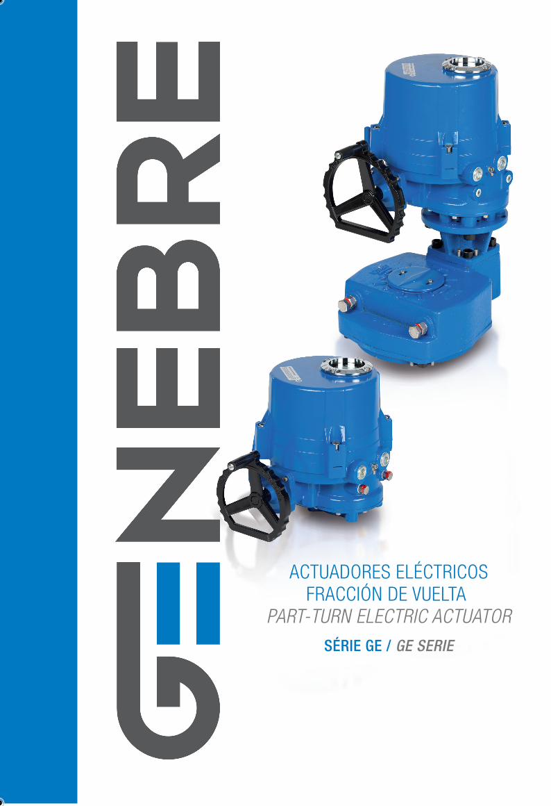
SÉRIE GE / GE SERIE
EDIFICIO GENEBRE. Av. de Joan Carles I , 46-48
08908 L’Hospitalet de Llobregat. Barcelona (Spain)
Nacional: Tel. +34 932 988 001. Fax. +34 932 988 006
Exportación: Tel. +34 932 988 000. Fax. +34 932 988 008
[email protected] - www.genebre.es
Servicio de Atención Técnica al Cliente: 902 504 203
ACTUADORES ELÉCTRICOSFRACCIÓN DE VUELTA
PART-TURN ELECTRIC ACTUATOR
ACTUADORES ELECTRICOS FRACCIÓN DE VUELTA PART-TURN ELECTRIC ACTUATOR
características / features
datos eléctricos / electric datas
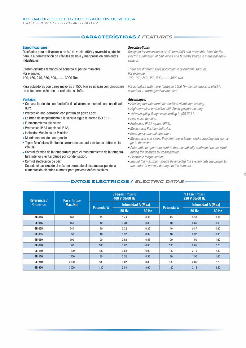
Especificaciones:Diseñados para aplicaciones de ¼” de vuelta (90º) y reversibles, ideales para la automatización de válvulas de bola y mariposas en ambientes industriales.
Existen distintos tamaños de acuerdo al par de maniobra:Por ejemplo:100, 160, 240, 350, 500,...…. 3000 Nm.
Para actuadores con pares mayores a 1500 Nm se utilizan combinaciones de actuadores eléctricos + reductores sinfín.
Ventajas:Carcasa fabricada con fundición de aleación de aluminio con anodinado duro. Protección anti-corrosión con pintura en polvo Epoxi.La brida de acoplamiento a la válvula sigue la norma ISO 5211.Funcionamiento silencioso.Protección IP 67 (opcional IP 68).Indicador Mecánico de Posición.Mando manual de emergencia. Topes Mecánicos, limitan la carrera del actuador evitando daños en la válvula.Control térmico de la temperatura para el mantenimiento de la tempera-tura interior y evitar daños por condensación.Control electrónico de par:Cuando el par excede el máximo permitido el sistema suspende la alimentación eléctrica al motor para prevenir daños posibles.
Specifications:Designed for applications of ¼” turn (90º) and reversible, ideal for the electric automation of ball valves and butterfly valves in industrial appli-cations.
There are different sizes according to operational torques:For example: 100, 160, 240, 350, 500,...…. 3000 Nm.
For actuators with more torque to 1500 Nm combinations of electric actuators + worm gearbox are used.
Advantages:Housing manufactured of anodised aluminium casting.High corrosion protection with Epoxy powder coating.Valve coupling flange is according to ISO 5211.Low noise function.Protection IP 67 (option IP68).Mechanical Position Indicator.Emergency manual operation.Mechanical end stops, they limit the actuator stroke avoiding any dama-ge to the valve.Automatic temperature control thermostatically controlled heater elimi-nating the damage by condensation.Electronic torque limiter:Should the maximum torque be exceded the system cuts the power to the motor to prevent damage to the actuator.
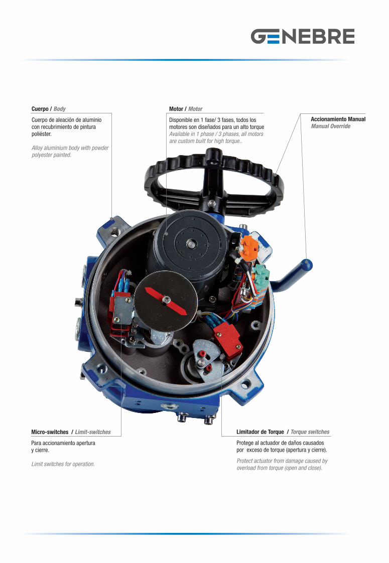
Micro-switches / Limit-switches
Para accionamiento aperturay cierre.
Limit switches for operation.
Cuerpo / Body
Cuerpo de aleación de aluminiocon recubrimiento de pintura poliéster.
Alloy aluminium body with powder polyester painted.
Motor / Motor
Disponible en 1 fase/ 3 fases, todos los motores son diseñados para un alto torqueAvailable in 1 phase / 3 phases, all motors are custom built for high torque..
Limitador de Torque / Torque switches
Protege al actuador de daños causados por exceso de torque (apertura y cierre).
Protect actuator from damage caused by overload from torque (open and close).
Accionamiento ManualManual Override
Distribuidor / Distributor:
Referencia / Reference
Par / TorqueMax. Nm
3 Fases / Phases400 V 50/60 Hz
1 Fase / Phase220 V 50/60 Hz
Potencia WIntensidad A (Max)
Potencia WIntensidad A (Max)
50 Hz 60 Hz 50 Hz 60 Hz
GE-010 100 15 0.43 0.33 15 0.52 0.58
GE-015 160 40 0.30 0.30 40 0.85 0.90
GE-025 240 40 0.32 0.32 40 0.87 0.90
GE-035 350 40 0.32 0.32 40 0.92 0.95
GE-050 500 90 0.52 0.56 90 1.50 1.60
GE-080 800 180 0.82 0.88 180 2.05 2.20
GE-110 1100 180 0.84 0.90 180 2.15 2.30
GE-150 1500 90 0.52 0.56 90 1.50 1.60
GE-210 2000 180 0.82 0.88 180 2.05 2.20
GE-300 3000 180 0.84 0.90 180 2.15 2.30
Cuadriptic actuadores 2012.indd 1 07/11/12 16:43
SÉRIE GE / GE SERIE
EDIFICIO GENEBRE. Av. de Joan Carles I , 46-48
08908 L’Hospitalet de Llobregat. Barcelona (Spain)
Nacional: Tel. +34 932 988 001. Fax. +34 932 988 006
Exportación: Tel. +34 932 988 000. Fax. +34 932 988 008
[email protected] - www.genebre.es
Servicio de Atención Técnica al Cliente: 902 504 203
ACTUADORES ELÉCTRICOSFRACCIÓN DE VUELTA
PART-TURN ELECTRIC ACTUATOR
ACTUADORES ELECTRICOS FRACCIÓN DE VUELTA PART-TURN ELECTRIC ACTUATOR
características / features
datos eléctricos / electric datas
Especificaciones:Diseñados para aplicaciones de ¼” de vuelta (90º) y reversibles, ideales para la automatización de válvulas de bola y mariposas en ambientes industriales.
Existen distintos tamaños de acuerdo al par de maniobra:Por ejemplo:100, 160, 240, 350, 500,...…. 3000 Nm.
Para actuadores con pares mayores a 1500 Nm se utilizan combinaciones de actuadores eléctricos + reductores sinfín.
Ventajas:Carcasa fabricada con fundición de aleación de aluminio con anodinado duro. Protección anti-corrosión con pintura en polvo Epoxi.La brida de acoplamiento a la válvula sigue la norma ISO 5211.Funcionamiento silencioso.Protección IP 67 (opcional IP 68).Indicador Mecánico de Posición.Mando manual de emergencia. Topes Mecánicos, limitan la carrera del actuador evitando daños en la válvula.Control térmico de la temperatura para el mantenimiento de la tempera-tura interior y evitar daños por condensación.Control electrónico de par:Cuando el par excede el máximo permitido el sistema suspende la alimentación eléctrica al motor para prevenir daños posibles.
Specifications:Designed for applications of ¼” turn (90º) and reversible, ideal for the electric automation of ball valves and butterfly valves in industrial appli-cations.
There are different sizes according to operational torques:For example: 100, 160, 240, 350, 500,...…. 3000 Nm.
For actuators with more torque to 1500 Nm combinations of electric actuators + worm gearbox are used.
Advantages:Housing manufactured of anodised aluminium casting.High corrosion protection with Epoxy powder coating.Valve coupling flange is according to ISO 5211.Low noise function.Protection IP 67 (option IP68).Mechanical Position Indicator.Emergency manual operation.Mechanical end stops, they limit the actuator stroke avoiding any dama-ge to the valve.Automatic temperature control thermostatically controlled heater elimi-nating the damage by condensation.Electronic torque limiter:Should the maximum torque be exceded the system cuts the power to the motor to prevent damage to the actuator.
Micro-switches / Limit-switches
Para accionamiento aperturay cierre.
Limit switches for operation.
Cuerpo / Body
Cuerpo de aleación de aluminiocon recubrimiento de pintura poliéster.
Alloy aluminium body with powder polyester painted.
Motor / Motor
Disponible en 1 fase/ 3 fases, todos los motores son diseñados para un alto torqueAvailable in 1 phase / 3 phases, all motors are custom built for high torque..
Limitador de Torque / Torque switches
Protege al actuador de daños causados por exceso de torque (apertura y cierre).
Protect actuator from damage caused by overload from torque (open and close).
Accionamiento ManualManual Override
Distribuidor / Distributor:
Referencia / Reference
Par / TorqueMax. Nm
3 Fases / Phases400 V 50/60 Hz
1 Fase / Phase220 V 50/60 Hz
Potencia WIntensidad A (Max)
Potencia WIntensidad A (Max)
50 Hz 60 Hz 50 Hz 60 Hz
GE-010 100 15 0.43 0.33 15 0.52 0.58
GE-015 160 40 0.30 0.30 40 0.85 0.90
GE-025 240 40 0.32 0.32 40 0.87 0.90
GE-035 350 40 0.32 0.32 40 0.92 0.95
GE-050 500 90 0.52 0.56 90 1.50 1.60
GE-080 800 180 0.82 0.88 180 2.05 2.20
GE-110 1100 180 0.84 0.90 180 2.15 2.30
GE-150 1500 90 0.52 0.56 90 1.50 1.60
GE-210 2000 180 0.82 0.88 180 2.05 2.20
GE-300 3000 180 0.84 0.90 180 2.15 2.30
Cuadriptic actuadores 2012.indd 1 07/11/12 16:43
ACTUADORES ELECTRICOS FRACCIÓN DE VUELTA PART-TURN ELECTRIC ACTUATOR
configuración estándar / standard configuration opciones disponibles / options availabledatos técnicos / engineering datas
especificaciones generales / general specifications
Nº Denominación / Name
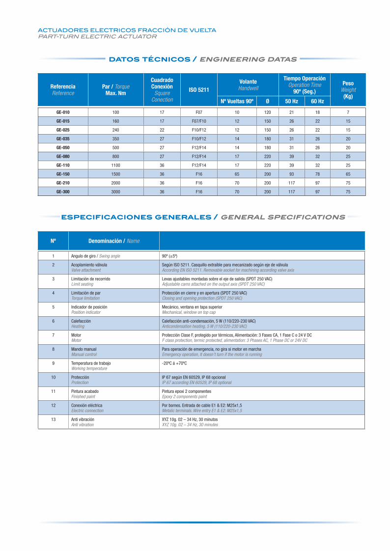
1 Angulo de giro / Swing angle 90º (±5º)
2 Acoplamiento válvulaValve attachment
Según ISO 5211. Casquillo extraíble para mecanizado según eje de válvulaAccording EN ISO 5211. Removable socket for machining according valve axis
3 Limitación de recorridoLimit seating
Levas ajustables montadas sobre el eje de salida (SPDT 250 VAC)Adjustable cams attached on the output axis (SPDT 250 VAC)
4 Limitación de parTorque limitation
Protección en cierre y en apertura (SPDT 250 VAC)Closing and opening protection (SPDT 250 VAC)
5 Indicador de posiciónPosition indicator
Mecánico, ventana en tapa superiorMechanical, window on top cap
6 CalefacciónHeating
Calefacción anti-condensación, 5 W (110/220-230 VAC)Anticondensation heating, 5 W (110/220-230 VAC)
7 MotorMotor
Protección Clase F, protegido por térmicos, Alimentación: 3 Fases CA, 1 Fase C o 24 V DCF class protection, termic protected, alimentation: 3 Phases AC, 1 Phase DC or 24V DC
8 Mando manualManual control
Para operación de emergencia, no gira si motor en marchaEmergency operation, It doesn’t turn if the motor is running
9 Temperatura de trabajoWorking temperature
-20ºC á +70ºC
10 ProtecciónProtection
IP 67 según EN 60529, IP 68 opcionalIP 67 according EN 60529, IP 68 optional
11 Pintura acabadoFinished paint
Pintura epoxi 2 componentesEpoxy 2 components paint
12 Conexión eléctricaElectric connection
Por bornes. Entrada de cable E1 & E2: M25x1,5Metalic terminals. Wire entry E1 & E2: M25x1,5
13 Anti vibraciónAnti vibration
XYZ 10g. 02 – 34 Hz, 30 minutosXYZ 10g. 02 – 34 Hz, 30 minutes
ReferenciaReference
Par / TorqueMax. Nm
CuadradoConexión
SquareConection
ISO 5211VolanteHandwell
Tiempo OperaciónOperation Time
90º (Seg.)Peso
Weight(Kg)
Nº Vueltas 90º Ø 50 Hz 60 Hz
GE-010 100 17 F07 10 120 21 18 7
GE-015 160 17 F07/F10 12 150 26 22 15
GE-025 240 22 F10/F12 12 150 26 22 15
GE-035 350 27 F10/F12 14 180 31 26 20
GE-050 500 27 F12/F14 14 180 31 26 20
GE-080 800 27 F12/F14 17 220 39 32 25
GE-110 1100 36 F12/F14 17 220 39 32 25
GE-150 1500 36 F16 65 200 93 78 65
GE-210 2000 36 F16 70 200 117 97 75
GE-300 3000 36 F16 70 200 117 97 75
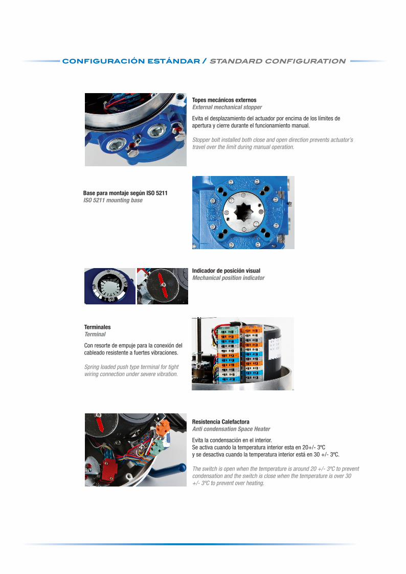
Topes mecánicos externos External mechanical stopper
Evita el desplazamiento del actuador por encima de los límites de apertura y cierre durante el funcionamiento manual.
Stopper bolt installed both close and open direction prevents actuator’s travel over the limit during manual operation.
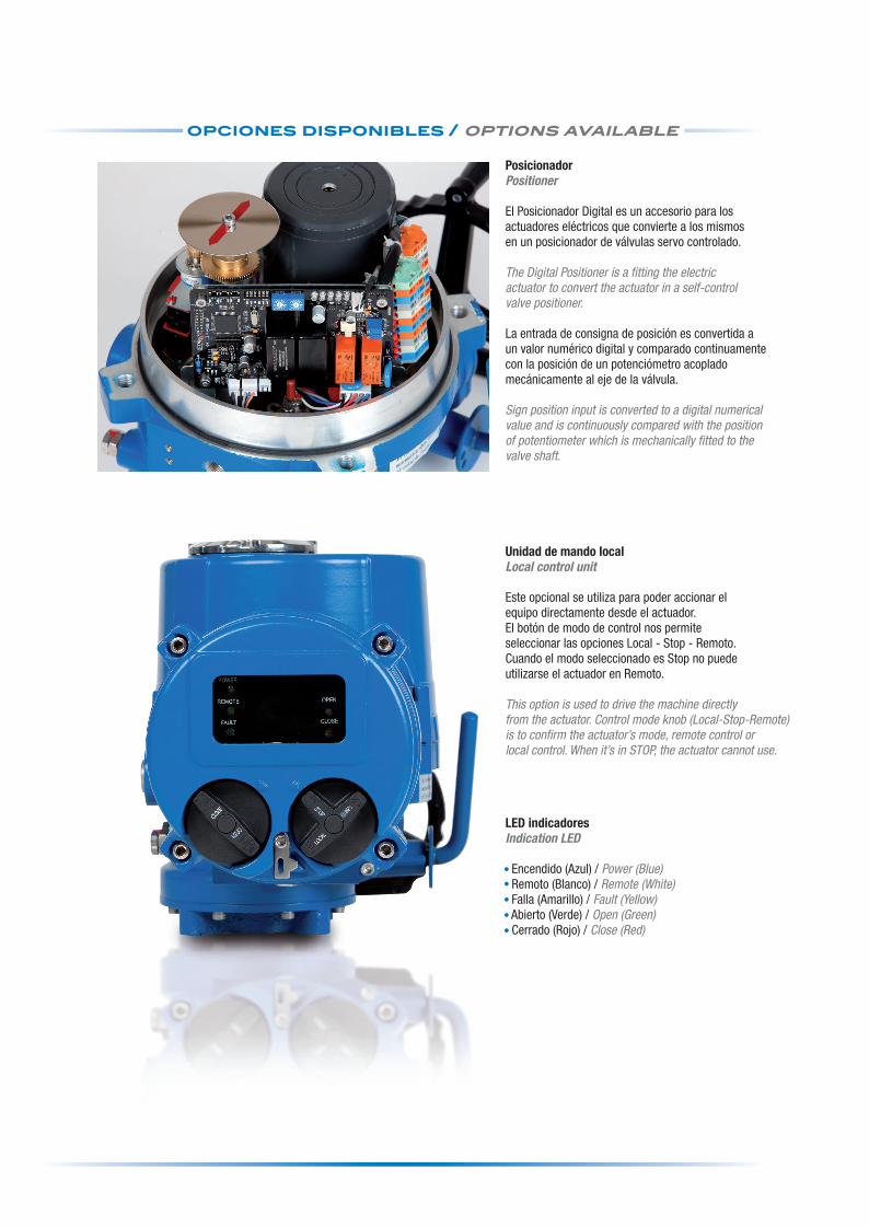
Posicionador Positioner
El Posicionador Digital es un accesorio para losactuadores eléctricos que convierte a los mismosen un posicionador de válvulas servo controlado.
The Digital Positioner is a fitting the electricactuator to convert the actuator in a self-controlvalve positioner.
La entrada de consigna de posición es convertida aun valor numérico digital y comparado continuamentecon la posición de un potenciómetro acopladomecánicamente al eje de la válvula.
Sign position input is converted to a digital numericalvalue and is continuously compared with the positionof potentiometer which is mechanically fitted to thevalve shaft.
Unidad de mando localLocal control unit
Este opcional se utiliza para poder accionar elequipo directamente desde el actuador.El botón de modo de control nos permiteseleccionar las opciones Local - Stop - Remoto.Cuando el modo seleccionado es Stop no puedeutilizarse el actuador en Remoto.
This option is used to drive the machine directlyfrom the actuator. Control mode knob (Local-Stop-Remote)is to confirm the actuator’s mode, remote control orlocal control. When it’s in STOP, the actuator cannot use.
LED indicadoresIndication LED
Encendido (Azul) / Power (Blue) Remoto (Blanco) / Remote (White) Falla (Amarillo) / Fault (Yellow) Abierto (Verde) / Open (Green) Cerrado (Rojo) / Close (Red)
Terminales Terminal
Con resorte de empuje para la conexión del cableado resistente a fuertes vibraciones.
Spring loaded push type terminal for tight wiring connection under severe vibration.
Resistencia CalefactoraAnti condensation Space Heater
Evita la condensación en el interior.Se activa cuando la temperatura interior esta en 20+/- 3ºCy se desactiva cuando la temperatura interior está en 30 +/- 3ºC.
The switch is open when the temperature is around 20 +/- 3ºC to prevent condensation and the switch is close when the temperature is over 30 +/- 3ºC to prevent over heating.
Indicador de posición visual Mechanical position indicator
Base para montaje según ISO 5211ISO 5211 mounting base
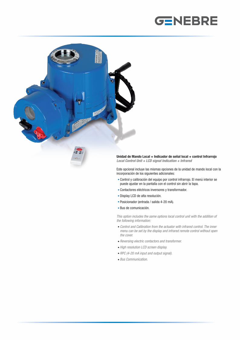
Unidad de Mando Local + Indicador de señal local + control Infrarrojo Local Control Unit + LCD signal Indication + Infrared
Este opcional incluye las mismas opciones de la unidad de mando local con la incorporación de los siguientes adicionales:
Control y calibración del equipo por control infrarrojo. El menú interior se puede ajustar en la pantalla con el control sin abrir la tapa.
Contactores eléctricos inversores y transformador.
Display LCD de alta resolución.
Posicionador (entrada / salida 4-20 mA).
Bus de comunicación.
This option includes the same options local control unit with the addition of the following information:
Control and Calibration from the actuator with infrared control. The inner menu can be set by the display and infrared remote control without open the cover.
Reversing electric contactors and transformer.
High resolution LCD screen display.
RPC (4-20 mA input and output signal).
Bus Communication.
Cuadriptic actuadores 2012.indd 2 07/11/12 16:43
ACTUADORES ELECTRICOS FRACCIÓN DE VUELTA PART-TURN ELECTRIC ACTUATOR
configuración estándar / standard configuration opciones disponibles / options availabledatos técnicos / engineering datas
especificaciones generales / general specifications
Nº Denominación / Name
1 Angulo de giro / Swing angle 90º (±5º)
2 Acoplamiento válvulaValve attachment
Según ISO 5211. Casquillo extraíble para mecanizado según eje de válvulaAccording EN ISO 5211. Removable socket for machining according valve axis
3 Limitación de recorridoLimit seating
Levas ajustables montadas sobre el eje de salida (SPDT 250 VAC)Adjustable cams attached on the output axis (SPDT 250 VAC)
4 Limitación de parTorque limitation
Protección en cierre y en apertura (SPDT 250 VAC)Closing and opening protection (SPDT 250 VAC)
5 Indicador de posiciónPosition indicator
Mecánico, ventana en tapa superiorMechanical, window on top cap
6 CalefacciónHeating
Calefacción anti-condensación, 5 W (110/220-230 VAC)Anticondensation heating, 5 W (110/220-230 VAC)
7 MotorMotor
Protección Clase F, protegido por térmicos, Alimentación: 3 Fases CA, 1 Fase C o 24 V DCF class protection, termic protected, alimentation: 3 Phases AC, 1 Phase DC or 24V DC
8 Mando manualManual control
Para operación de emergencia, no gira si motor en marchaEmergency operation, It doesn’t turn if the motor is running
9 Temperatura de trabajoWorking temperature
-20ºC á +70ºC
10 ProtecciónProtection
IP 67 según EN 60529, IP 68 opcionalIP 67 according EN 60529, IP 68 optional
11 Pintura acabadoFinished paint
Pintura epoxi 2 componentesEpoxy 2 components paint
12 Conexión eléctricaElectric connection
Por bornes. Entrada de cable E1 & E2: M25x1,5Metalic terminals. Wire entry E1 & E2: M25x1,5
13 Anti vibraciónAnti vibration
XYZ 10g. 02 – 34 Hz, 30 minutosXYZ 10g. 02 – 34 Hz, 30 minutes
ReferenciaReference
Par / TorqueMax. Nm
CuadradoConexión
SquareConection
ISO 5211VolanteHandwell
Tiempo OperaciónOperation Time
90º (Seg.)Peso
Weight(Kg)
Nº Vueltas 90º Ø 50 Hz 60 Hz
GE-010 100 17 F07 10 120 21 18 7
GE-015 160 17 F07/F10 12 150 26 22 15
GE-025 240 22 F10/F12 12 150 26 22 15
GE-035 350 27 F10/F12 14 180 31 26 20
GE-050 500 27 F12/F14 14 180 31 26 20
GE-080 800 27 F12/F14 17 220 39 32 25
GE-110 1100 36 F12/F14 17 220 39 32 25
GE-150 1500 36 F16 65 200 93 78 65
GE-210 2000 36 F16 70 200 117 97 75
GE-300 3000 36 F16 70 200 117 97 75
Topes mecánicos externos External mechanical stopper
Evita el desplazamiento del actuador por encima de los límites de apertura y cierre durante el funcionamiento manual.
Stopper bolt installed both close and open direction prevents actuator’s travel over the limit during manual operation.
Posicionador Positioner
El Posicionador Digital es un accesorio para losactuadores eléctricos que convierte a los mismosen un posicionador de válvulas servo controlado.
The Digital Positioner is a fitting the electricactuator to convert the actuator in a self-controlvalve positioner.
La entrada de consigna de posición es convertida aun valor numérico digital y comparado continuamentecon la posición de un potenciómetro acopladomecánicamente al eje de la válvula.
Sign position input is converted to a digital numericalvalue and is continuously compared with the positionof potentiometer which is mechanically fitted to thevalve shaft.
Unidad de mando localLocal control unit
Este opcional se utiliza para poder accionar elequipo directamente desde el actuador.El botón de modo de control nos permiteseleccionar las opciones Local - Stop - Remoto.Cuando el modo seleccionado es Stop no puedeutilizarse el actuador en Remoto.
This option is used to drive the machine directlyfrom the actuator. Control mode knob (Local-Stop-Remote)is to confirm the actuator’s mode, remote control orlocal control. When it’s in STOP, the actuator cannot use.
LED indicadoresIndication LED
Encendido (Azul) / Power (Blue) Remoto (Blanco) / Remote (White) Falla (Amarillo) / Fault (Yellow) Abierto (Verde) / Open (Green) Cerrado (Rojo) / Close (Red)
Terminales Terminal
Con resorte de empuje para la conexión del cableado resistente a fuertes vibraciones.
Spring loaded push type terminal for tight wiring connection under severe vibration.
Resistencia CalefactoraAnti condensation Space Heater
Evita la condensación en el interior.Se activa cuando la temperatura interior esta en 20+/- 3ºCy se desactiva cuando la temperatura interior está en 30 +/- 3ºC.
The switch is open when the temperature is around 20 +/- 3ºC to prevent condensation and the switch is close when the temperature is over 30 +/- 3ºC to prevent over heating.
Indicador de posición visual Mechanical position indicator
Base para montaje según ISO 5211ISO 5211 mounting base
Unidad de Mando Local + Indicador de señal local + control Infrarrojo Local Control Unit + LCD signal Indication + Infrared
Este opcional incluye las mismas opciones de la unidad de mando local con la incorporación de los siguientes adicionales:
Control y calibración del equipo por control infrarrojo. El menú interior se puede ajustar en la pantalla con el control sin abrir la tapa.
Contactores eléctricos inversores y transformador.
Display LCD de alta resolución.
Posicionador (entrada / salida 4-20 mA).
Bus de comunicación.
This option includes the same options local control unit with the addition of the following information:
Control and Calibration from the actuator with infrared control. The inner menu can be set by the display and infrared remote control without open the cover.
Reversing electric contactors and transformer.
High resolution LCD screen display.
RPC (4-20 mA input and output signal).
Bus Communication.
Cuadriptic actuadores 2012.indd 2 07/11/12 16:43
SÉRIE GE / GE SERIE
EDIFICIO GENEBRE. Av. de Joan Carles I , 46-48
08908 L’Hospitalet de Llobregat. Barcelona (Spain)
Nacional: Tel. +34 932 988 001. Fax. +34 932 988 006
Exportación: Tel. +34 932 988 000. Fax. +34 932 988 008
[email protected] - www.genebre.es
Servicio de Atención Técnica al Cliente: 902 504 203
ACTUADORES ELÉCTRICOSFRACCIÓN DE VUELTA
PART-TURN ELECTRIC ACTUATOR
ACTUADORES ELECTRICOS FRACCIÓN DE VUELTA PART-TURN ELECTRIC ACTUATOR
características / features
datos eléctricos / electric datas
Especificaciones:Diseñados para aplicaciones de ¼” de vuelta (90º) y reversibles, ideales para la automatización de válvulas de bola y mariposas en ambientes industriales.
Existen distintos tamaños de acuerdo al par de maniobra:Por ejemplo:100, 160, 240, 350, 500,...…. 3000 Nm.
Para actuadores con pares mayores a 1500 Nm se utilizan combinaciones de actuadores eléctricos + reductores sinfín.
Ventajas:Carcasa fabricada con fundición de aleación de aluminio con anodinado duro. Protección anti-corrosión con pintura en polvo Epoxi.La brida de acoplamiento a la válvula sigue la norma ISO 5211.Funcionamiento silencioso.Protección IP 67 (opcional IP 68).Indicador Mecánico de Posición.Mando manual de emergencia. Topes Mecánicos, limitan la carrera del actuador evitando daños en la válvula.Control térmico de la temperatura para el mantenimiento de la tempera-tura interior y evitar daños por condensación.Control electrónico de par:Cuando el par excede el máximo permitido el sistema suspende la alimentación eléctrica al motor para prevenir daños posibles.
Specifications:Designed for applications of ¼” turn (90º) and reversible, ideal for the electric automation of ball valves and butterfly valves in industrial appli-cations.
There are different sizes according to operational torques:For example: 100, 160, 240, 350, 500,...…. 3000 Nm.
For actuators with more torque to 1500 Nm combinations of electric actuators + worm gearbox are used.
Advantages:Housing manufactured of anodised aluminium casting.High corrosion protection with Epoxy powder coating.Valve coupling flange is according to ISO 5211.Low noise function.Protection IP 67 (option IP68).Mechanical Position Indicator.Emergency manual operation.Mechanical end stops, they limit the actuator stroke avoiding any dama-ge to the valve.Automatic temperature control thermostatically controlled heater elimi-nating the damage by condensation.Electronic torque limiter:Should the maximum torque be exceded the system cuts the power to the motor to prevent damage to the actuator.
Micro-switches / Limit-switches
Para accionamiento aperturay cierre.
Limit switches for operation.
Cuerpo / Body
Cuerpo de aleación de aluminiocon recubrimiento de pintura poliéster.
Alloy aluminium body with powder polyester painted.
Motor / Motor
Disponible en 1 fase/ 3 fases, todos los motores son diseñados para un alto torqueAvailable in 1 phase / 3 phases, all motors are custom built for high torque..
Limitador de Torque / Torque switches
Protege al actuador de daños causados por exceso de torque (apertura y cierre).
Protect actuator from damage caused by overload from torque (open and close).
Accionamiento ManualManual Override
Distribuidor / Distributor:
Referencia / Reference
Par / TorqueMax. Nm
3 Fases / Phases400 V 50/60 Hz
1 Fase / Phase220 V 50/60 Hz
Potencia WIntensidad A (Max)
Potencia WIntensidad A (Max)
50 Hz 60 Hz 50 Hz 60 Hz
GE-010 100 15 0.43 0.33 15 0.52 0.58
GE-015 160 40 0.30 0.30 40 0.85 0.90
GE-025 240 40 0.32 0.32 40 0.87 0.90
GE-035 350 40 0.32 0.32 40 0.92 0.95
GE-050 500 90 0.52 0.56 90 1.50 1.60
GE-080 800 180 0.82 0.88 180 2.05 2.20
GE-110 1100 180 0.84 0.90 180 2.15 2.30
GE-150 1500 90 0.52 0.56 90 1.50 1.60
GE-210 2000 180 0.82 0.88 180 2.05 2.20
GE-300 3000 180 0.84 0.90 180 2.15 2.30
Cuadriptic actuadores 2012.indd 1 07/11/12 16:43