Embed Size (px)
DESCRIPTION
A colection of my early engine designs as an aerospace engineering student.
Citation preview
Aerospace inventics-visual guide
Valeriu Drãgan©
Bucharest 2010
ISBN:978-973-0-09403-9
2

foreword
• The things that are truly
important in life are not
the ones nobody has done
before but the ones that
everyone needs to do.
• Simplification is one of
the most difficult things to
do. That‟s why the ability
to think in a simple way is
so important.
3

4
Contents
• Rotary engines
• Steam engines
• The plano-reactor
• The X-Mass tree turboprop
• The dual core turbofan
• Some history
• The turbo-helix
• Magnetic non-contact cogged wheels
• Sketches for magnetic gearing
• Unconventional compressor turbofan engines
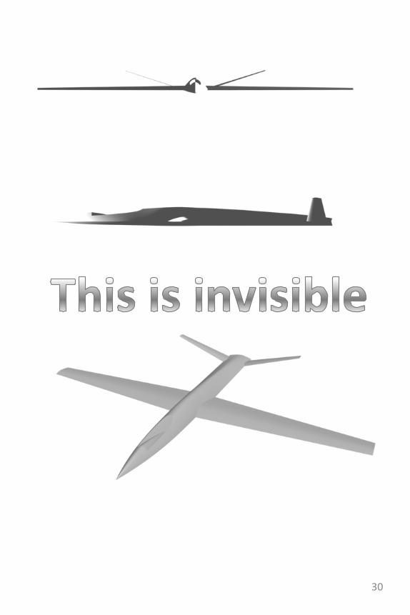
• This is invisible
• Micro-UAV concept
• Other studies stealth jet trainer
• Supercirculation hovering stealth aircraft study
• A modular centrifugal compressor study
• Two stage centrifugal compressor study
• The wind milling enginealso known as theRam Turbine Engine
• Another perspective
• Other variations on the ram turbojet
• -the gyrocopter study
• -the anemometric turbo-jet configurations
• -the slim, variable pitch ram air turbine jet engine
• The MAMuT
• Taking the MAMuT one step further
5
contents
• A fluid gyroscope
• Tip jet evolution
• Tip jet studies
• Micro-turbine propeller
• Hydrogen peroxide power plant
• Nuclear Turbofans
• SANDRa
• Stator heat exchangers for advanced cycle turbofan engines
• From A to C trough B.5
• The cube
• The cuboid engine with hyper modularity
• In operation
• Other considerations regarding the cuboid engine
• Tip compressor turbofan study
• The semi-pressurized burner turbofan
• Supercirculation vs. countercirculation
• The Maximal Attitude Immediate Response Actuator
• The Rhino Chevron and diamond canards
• The negative delta wing and diamond canards
• The ways conventional wings and Delta wings produce lift
• The negative delta
• Diamond canards
• On their ownand on the aircraft
6

7
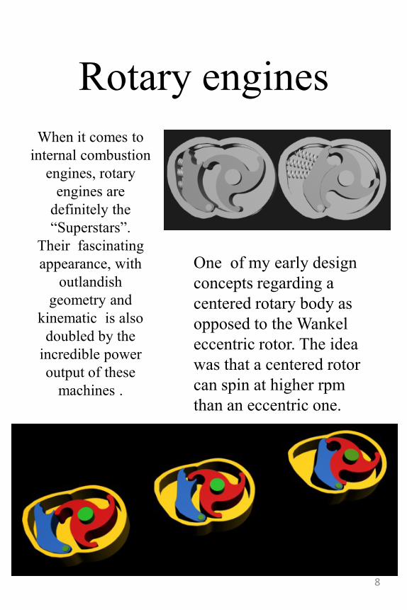
Rotary engines
When it comes to
internal combustion
engines, rotary
engines are
definitely the
“Superstars”.
Their fascinating
appearance, with
outlandish
geometry and
kinematic is also
doubled by the
incredible power
output of these
machines .
One of my early design
concepts regarding a
centered rotary body as
opposed to the Wankel
eccentric rotor. The idea
was that a centered rotor
can spin at higher rpm
than an eccentric one.
8
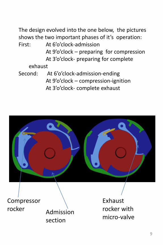
The design evolved into the one below, the pictures shows the two important phases of it’s operation: First: At 6’o’clock-admission
At 9’o’clock – preparing for compressionAt 3’o’clock- preparing for complete
exhaustSecond: At 6’o’clock-admission-ending
At 9’o’clock – compression-ignitionAt 3’o’clock- complete exhaust
Compressor rocker Admission
section
Exhaust rocker with micro-valve
9
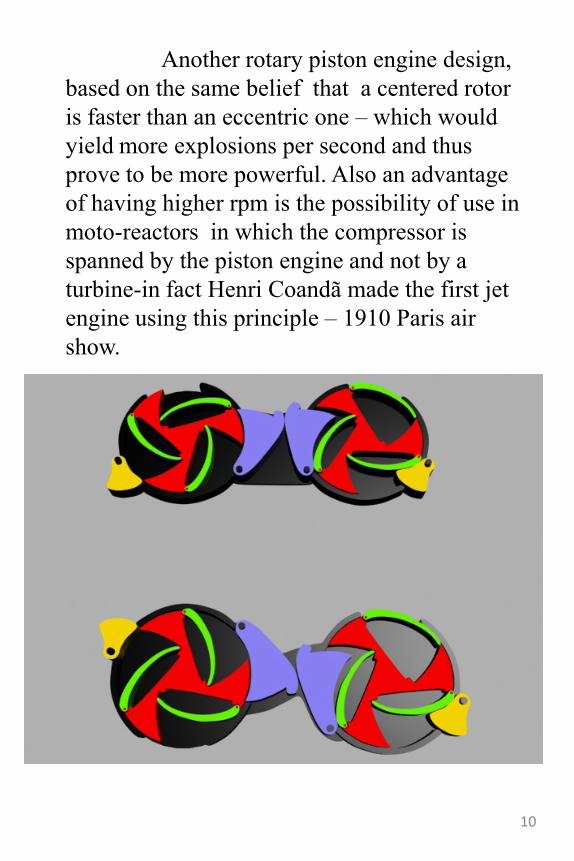
Another rotary piston engine design,
based on the same belief that a centered rotor
is faster than an eccentric one – which would
yield more explosions per second and thus
prove to be more powerful. Also an advantage
of having higher rpm is the possibility of use in
moto-reactors in which the compressor is
spanned by the piston engine and not by a
turbine-in fact Henri Coandã made the first jet
engine using this principle – 1910 Paris air
show.
10
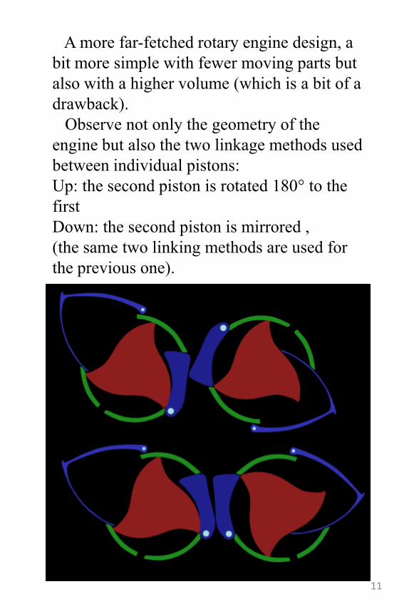
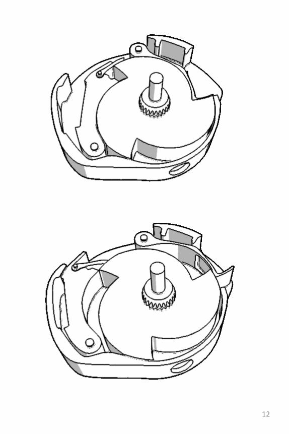
A more far-fetched rotary engine design, a
bit more simple with fewer moving parts but
also with a higher volume (which is a bit of a
drawback).
Observe not only the geometry of the
engine but also the two linkage methods used
between individual pistons:
Up: the second piston is rotated 180° to the
first
Down: the second piston is mirrored ,
(the same two linking methods are used for
the previous one).
11
12
Steam engines• The steam engine has been at the forefront of
engineering for decades, most early brilliant
engineers derived theories and developed
outstandingly complex machines.
• As a measure of relevance, the Wankel engine
a lot of people praise had a steam “cousin”. The
rotor geometry was the same Reuleaux triangle
and the chamber was quite similar in shape too.
Of course it only worked by extracting work
from the steam and not by compressing and
igniting mixtures of air and petrol but the point
is that if it‟s mechanical complexity and
ingenuity you‟re after, you should definitely
take a look at as much steam engines as
possible.
• Another interesting bit is that George
Brayton‟s initial engine worked as an internal
combustion engine using only steam engine
parts: The compression cylinder, the expansion
cylinder and a burner in between. The same
principle governs modern day turbine engines
only the cylinders are replaced by bladed
machinery-which can accommodate a much
higher flow of work fluid. 13
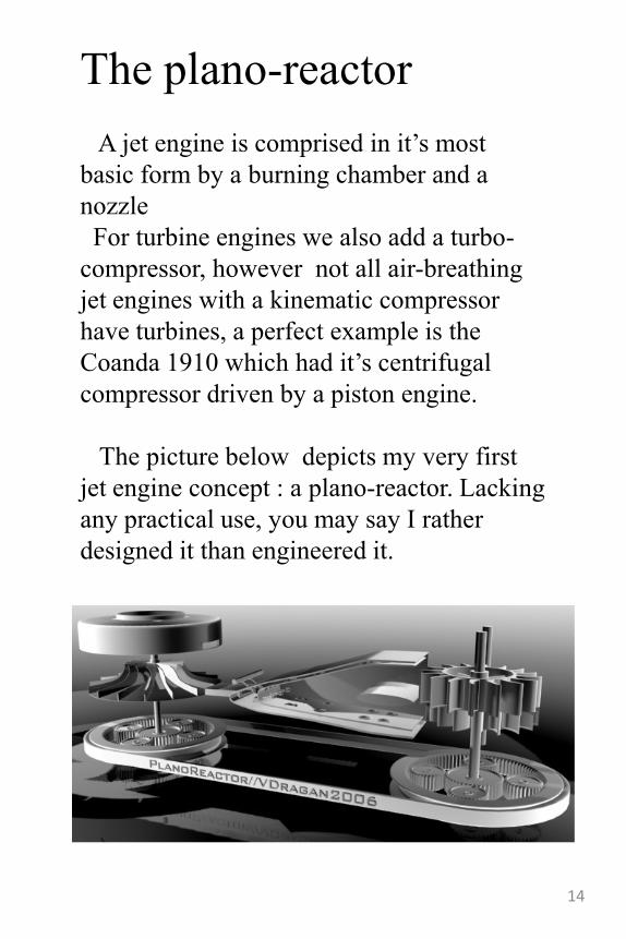
The plano-reactor
A jet engine is comprised in it‟s most
basic form by a burning chamber and a
nozzle
For turbine engines we also add a turbo-
compressor, however not all air-breathing
jet engines with a kinematic compressor
have turbines, a perfect example is the
Coanda 1910 which had it‟s centrifugal
compressor driven by a piston engine.
The picture below depicts my very first
jet engine concept : a plano-reactor. Lacking
any practical use, you may say I rather
designed it than engineered it.
14
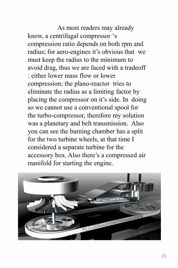
As most readers may already
know, a centrifugal compressor „s
compression ratio depends on both rpm and
radius; for aero-engines it‟s obvious that we
must keep the radius to the minimum to
avoid drag, thus we are faced with a tradeoff
: either lower mass flow or lower
compression; the plano-reactor tries to
eliminate the radius as a limiting factor by
placing the compressor on it‟s side. In doing
so we cannot use a conventional spool for
the turbo-compressor, therefore my solution
was a planetary and belt transmission. Also
you can see the burning chamber has a split
for the two turbine wheels, at that time I
considered a separate turbine for the
accessory box. Also there‟s a compressed air
manifold for starting the engine.
15
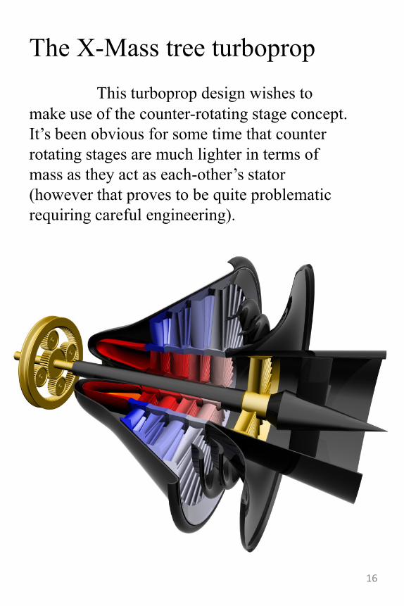
The X-Mass tree turboprop
This turboprop design wishes to
make use of the counter-rotating stage concept.
It‟s been obvious for some time that counter
rotating stages are much lighter in terms of
mass as they act as each-other‟s stator
(however that proves to be quite problematic
requiring careful engineering).
16
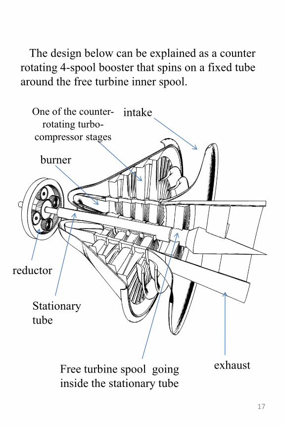
The design below can be explained as a counter
rotating 4-spool booster that spins on a fixed tube
around the free turbine inner spool.
intake
Stationary
tube
One of the counter-
rotating turbo-
compressor stages
burner
reductor
Free turbine spool going
inside the stationary tube
exhaust
17
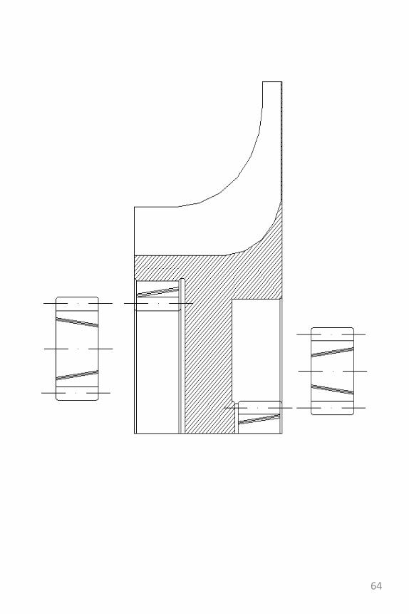
The dual core turbofan
• The dual core concept relies on the counter-rotating turbine/compressor stages on one hand and on the thrust optimization by increasing the core temperature on the other.
• As it can be seen, it has two burning chambers: one for the counter-rotating turbo-compressors and the other for propulsion. The accessory gearbox gets the power via a heat exchanger at the back of the nozzle.
• Separating the turbine combustor from the “core booster” can offer new possibilities for optimization in both engine performance such as thrust or efficiency without having to sacrifice one in favor of the other. It is also a good way to decrease maintenance cost by prolonging the active life of the turbine because the turbine inlet temperature can be lowered.
• This arrangement is somewhat similar in those aspects with the afterburning turbojet.
18
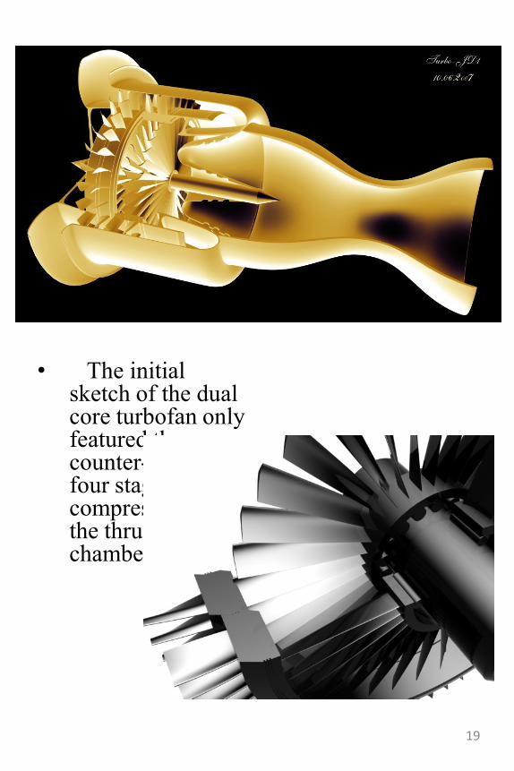
• The initial sketch of the dual core turbofan only featured the counter-rotating four stage turbo-compressors and the thrust core chamber
19
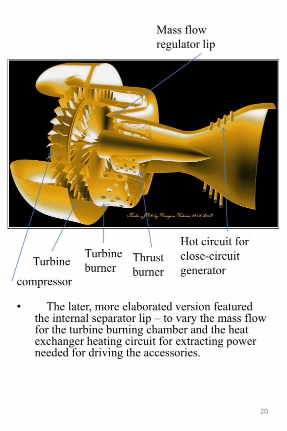
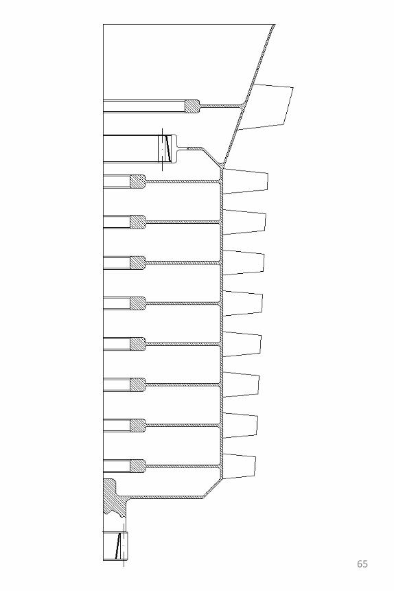
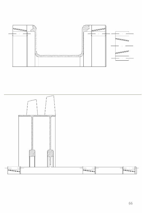
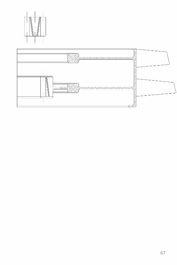
• The later, more elaborated version featured the internal separator lip – to vary the mass flow for the turbine burning chamber and the heat exchanger heating circuit for extracting power needed for driving the accessories.
Turbine
burnerThrust
burner
Hot circuit for
close-circuit
generatorTurbine
compressor
Mass flow
regulator lip
20
Some history
• In 1906 at Montesson-near Paris, France, Traian Vuiaachieved the first self-powered flight in the history of mankind. This may seem puzzling since we all know the first motorized flight was made by the Wright brothers a few years earlier..true but also a deceptive choice of words: motorized flight-yes, but the liftoff could not be achieved on engine power alone-they were catapulted; the fact that they had an engine on board only prolonged the flight.
21
22
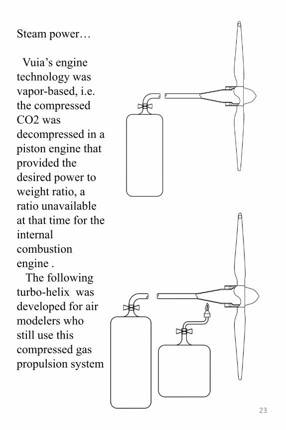
Steam power…
Vuia‟s engine
technology was
vapor-based, i.e.
the compressed
CO2 was
decompressed in a
piston engine that
provided the
desired power to
weight ratio, a
ratio unavailable
at that time for the
internal
combustion
engine .
The following
turbo-helix was
developed for air
modelers who
still use this
compressed gas
propulsion system
23
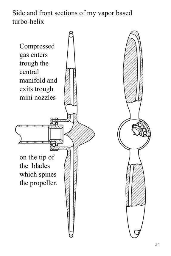
Side and front sections of my vapor based
turbo-helix
Compressed
gas enters
trough the
central
manifold and
exits trough
mini nozzles
on the tip of
the blades
which spines
the propeller.
24
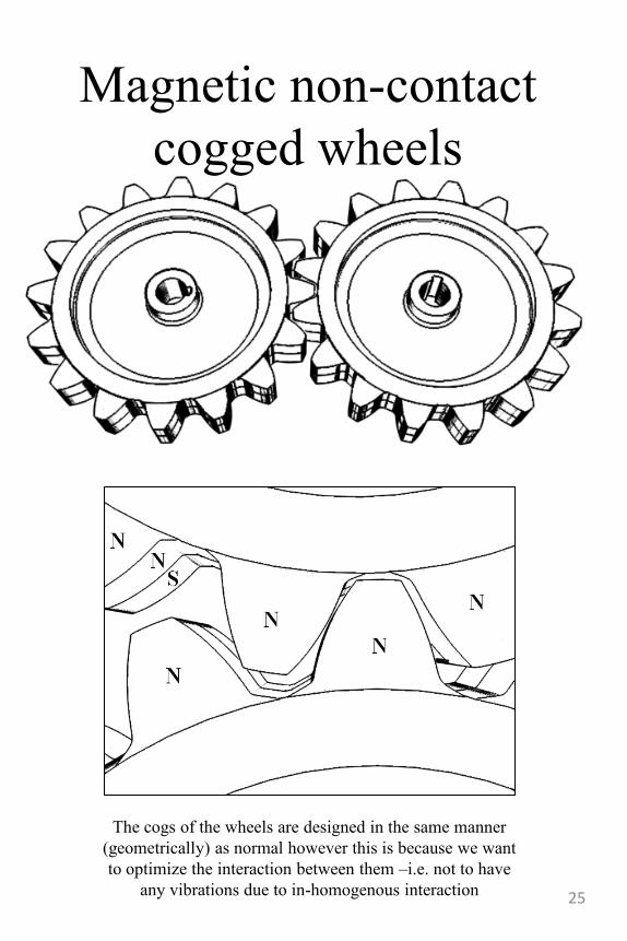
Magnetic non-contact
cogged wheels
The cogs of the wheels are designed in the same manner
(geometrically) as normal however this is because we want
to optimize the interaction between them –i.e. not to have
any vibrations due to in-homogenous interaction 25
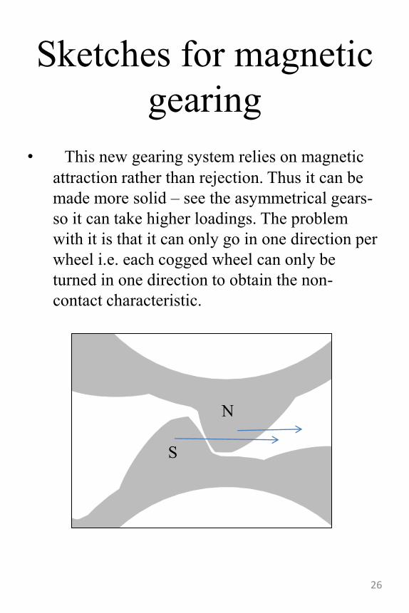
Sketches for magnetic
gearing
• This new gearing system relies on magnetic
attraction rather than rejection. Thus it can be
made more solid – see the asymmetrical gears-
so it can take higher loadings. The problem
with it is that it can only go in one direction per
wheel i.e. each cogged wheel can only be
turned in one direction to obtain the non-
contact characteristic.
N
S
26
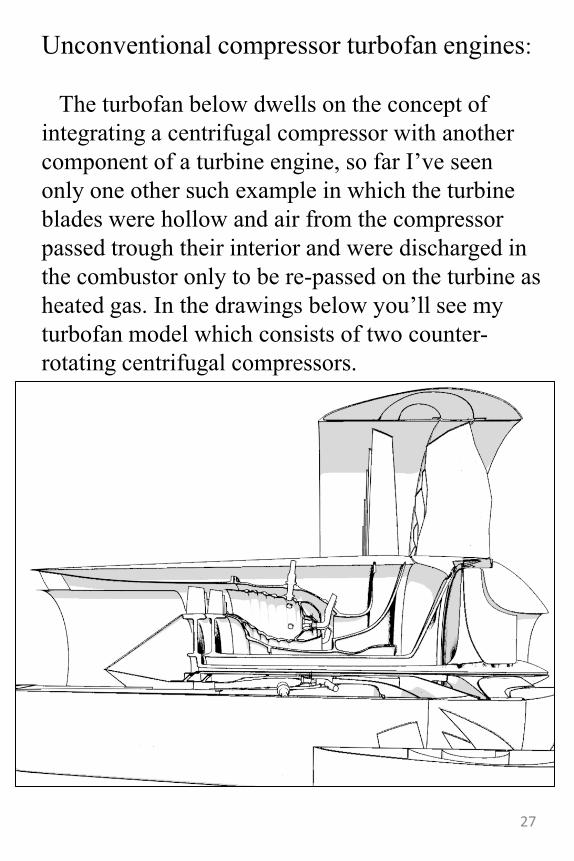
Unconventional compressor turbofan engines:
The turbofan below dwells on the concept of
integrating a centrifugal compressor with another
component of a turbine engine, so far I‟ve seen
only one other such example in which the turbine
blades were hollow and air from the compressor
passed trough their interior and were discharged in
the combustor only to be re-passed on the turbine as
heated gas. In the drawings below you‟ll see my
turbofan model which consists of two counter-
rotating centrifugal compressors.
27
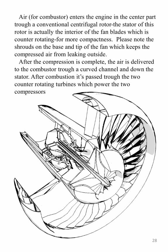
Air (for combustor) enters the engine in the center part
trough a conventional centrifugal rotor-the stator of this
rotor is actually the interior of the fan blades which is
counter rotating-for more compactness. Please note the
shrouds on the base and tip of the fan which keeps the
compressed air from leaking outside.
After the compression is complete, the air is delivered
to the combustor trough a curved channel and down the
stator. After combustion it‟s passed trough the two
counter rotating turbines which power the two
compressors
28
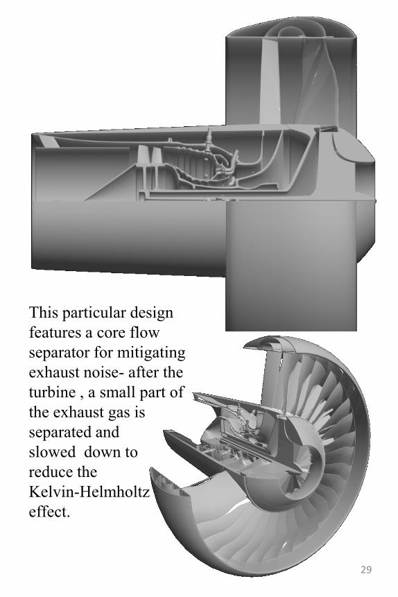
This particular design
features a core flow
separator for mitigating
exhaust noise- after the
turbine , a small part of
the exhaust gas is
separated and
slowed down to
reduce the
Kelvin-Helmholtz
effect.
29
30
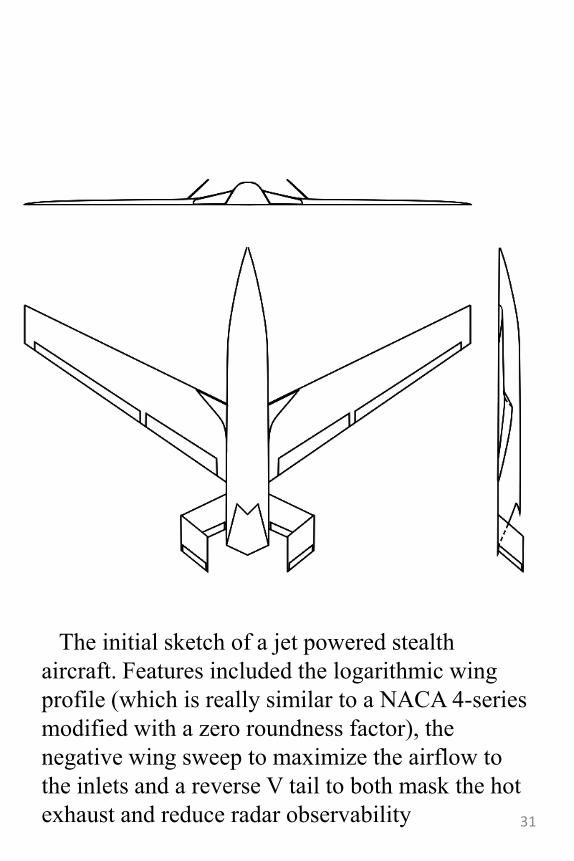
The initial sketch of a jet powered stealth
aircraft. Features included the logarithmic wing
profile (which is really similar to a NACA 4-series
modified with a zero roundness factor), the
negative wing sweep to maximize the airflow to
the inlets and a reverse V tail to both mask the hot
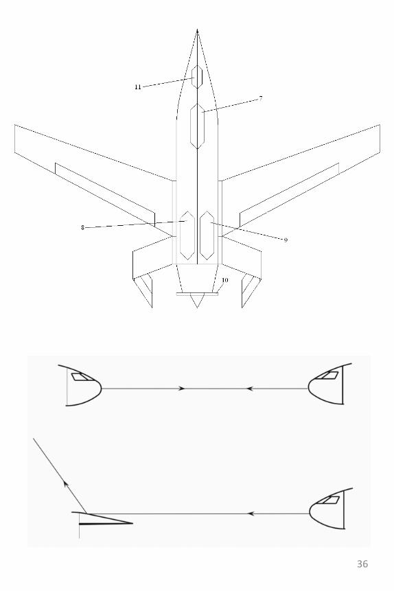
exhaust and reduce radar observability 31
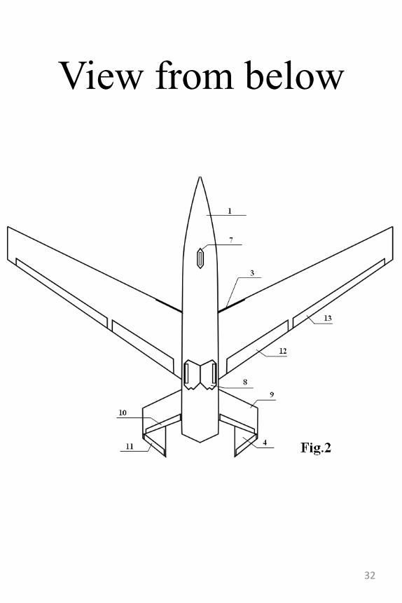
View from below
32
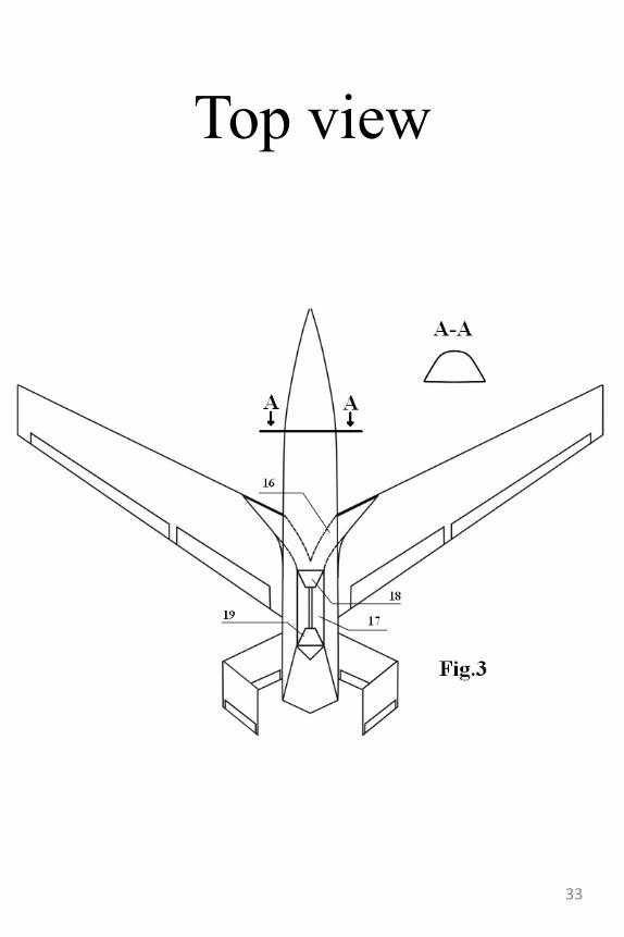
Top view
33
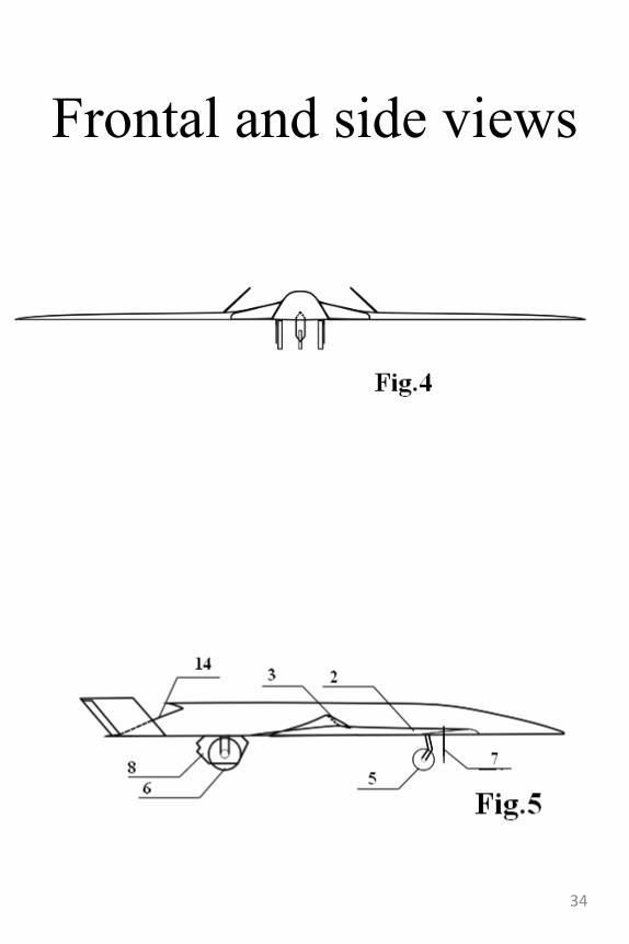
Frontal and side views
34
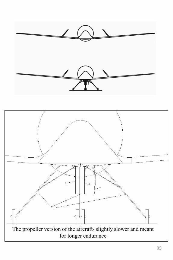
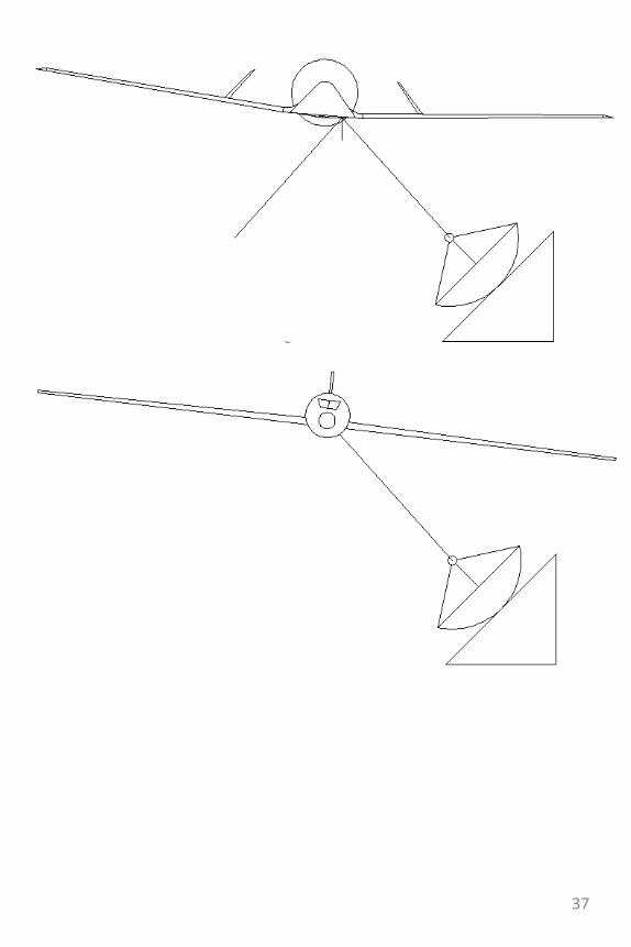
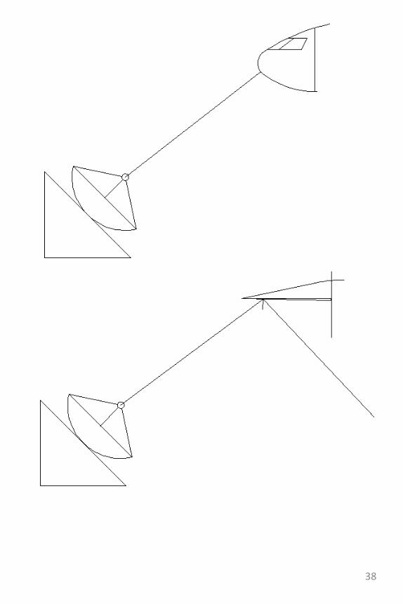
The propeller version of the aircraft- slightly slower and meant
for longer endurance
35
36
37
38
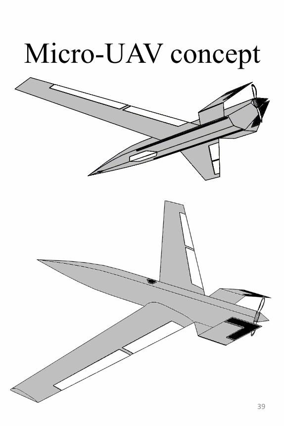
Micro-UAV concept
39
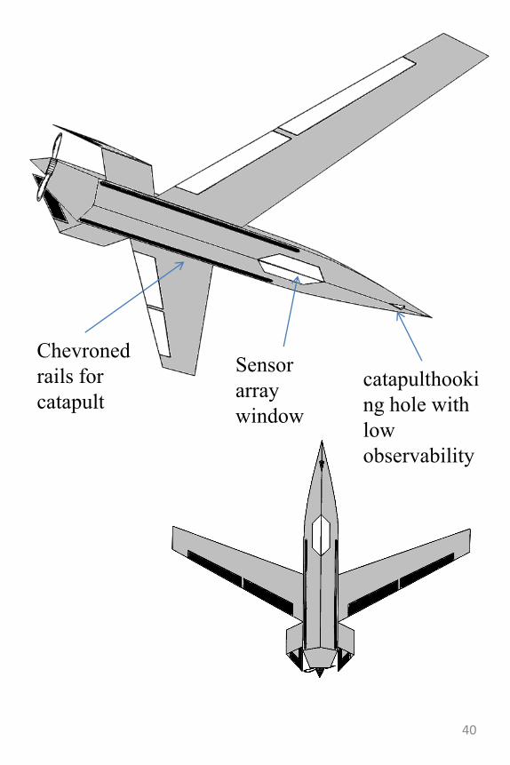
catapulthooki
ng hole with
low
observability
Chevroned
rails for
catapult
Sensor
array
window
40
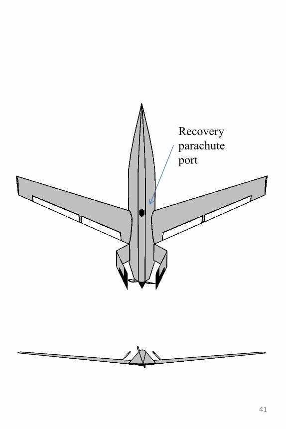
Recovery
parachute
port
41
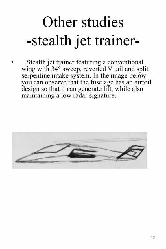
Other studies
-stealth jet trainer-
• Stealth jet trainer featuring a conventional wing with 34° sweep, reverted V tail and split serpentine intake system. In the image below you can observe that the fuselage has an airfoil design so that it can generate lift, while also maintaining a low radar signature.
42
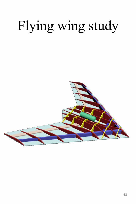
Flying wing study
43
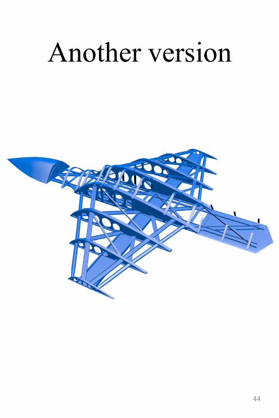
Another version
44
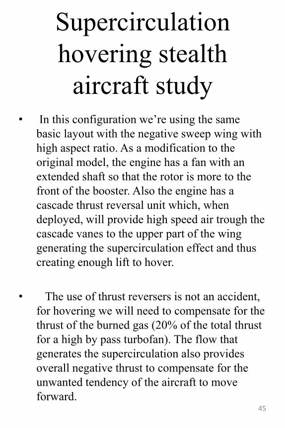
Supercirculation
hovering stealth
aircraft study• In this configuration we‟re using the same
basic layout with the negative sweep wing with
high aspect ratio. As a modification to the
original model, the engine has a fan with an
extended shaft so that the rotor is more to the
front of the booster. Also the engine has a
cascade thrust reversal unit which, when
deployed, will provide high speed air trough the
cascade vanes to the upper part of the wing
generating the supercirculation effect and thus
creating enough lift to hover.
• The use of thrust reversers is not an accident,
for hovering we will need to compensate for the
thrust of the burned gas (20% of the total thrust
for a high by pass turbofan). The flow that
generates the supercirculation also provides
overall negative thrust to compensate for the
unwanted tendency of the aircraft to move
forward.45
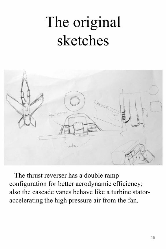
The original
sketches
The thrust reverser has a double ramp
configuration for better aerodynamic efficiency;
also the cascade vanes behave like a turbine stator-
accelerating the high pressure air from the fan.
46
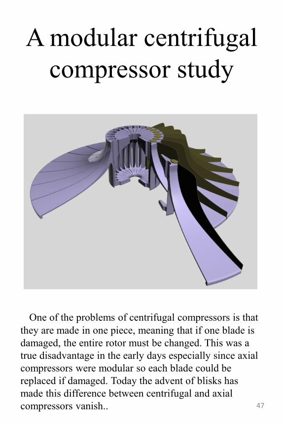
A modular centrifugal
compressor study
One of the problems of centrifugal compressors is that
they are made in one piece, meaning that if one blade is
damaged, the entire rotor must be changed. This was a
true disadvantage in the early days especially since axial
compressors were modular so each blade could be
replaced if damaged. Today the advent of blisks has
made this difference between centrifugal and axial
compressors vanish.. 47
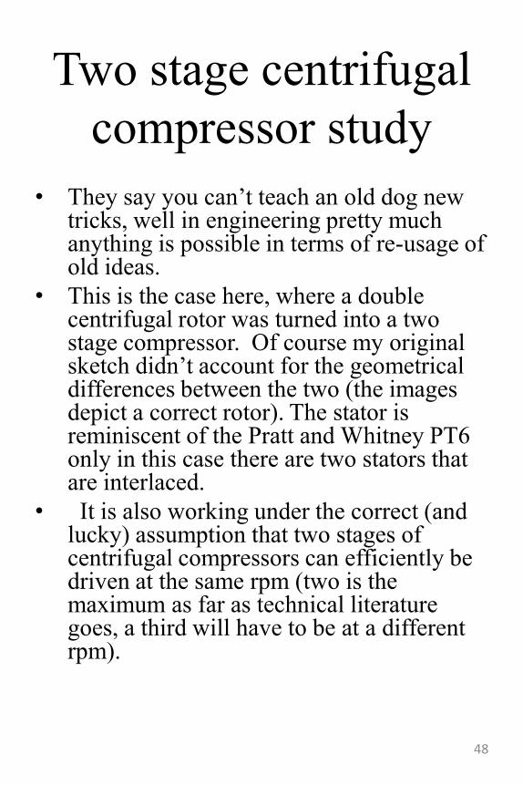
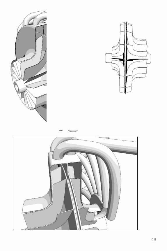
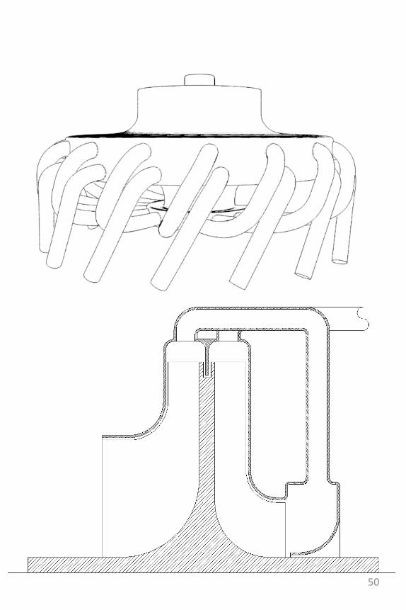
Two stage centrifugal
compressor study
• They say you can‟t teach an old dog new tricks, well in engineering pretty much anything is possible in terms of re-usage of old ideas.
• This is the case here, where a double centrifugal rotor was turned into a two stage compressor. Of course my original sketch didn‟t account for the geometrical differences between the two (the images depict a correct rotor). The stator is reminiscent of the Pratt and Whitney PT6 only in this case there are two stators that are interlaced.
• It is also working under the correct (and lucky) assumption that two stages of centrifugal compressors can efficiently be driven at the same rpm (two is the maximum as far as technical literature goes, a third will have to be at a different rpm).
48
49
50
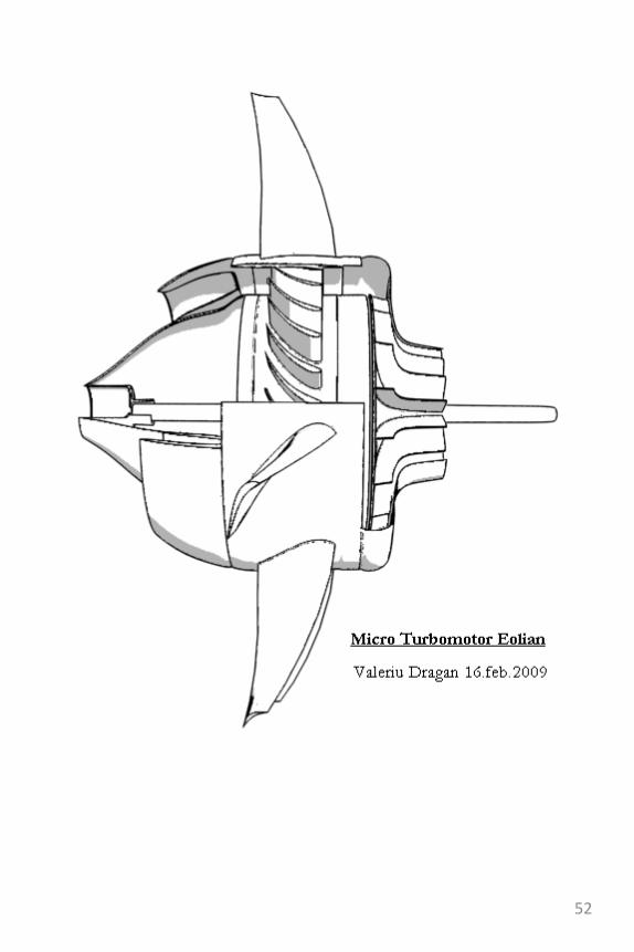
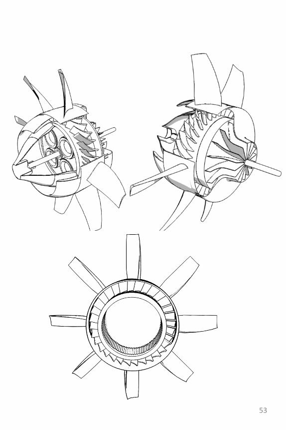
The wind milling engine
also known as the
Ram Turbine Engine• This turbine engine study is a
good example of wordplay, what began as a personal challenge turned out to be a completely uncharted technical field-a fertile one might I add..
• In fact this can also be a good example of one of Edward de Bono‟s theories about creativity.
• Also you may observe how old inventions, ideas and so on can be reused or combined to augment new ones, in this case I reused the two stage centrifugal compressor and also “stole” the principles of rocket launchers and aerospikenozzles.
51
52
53
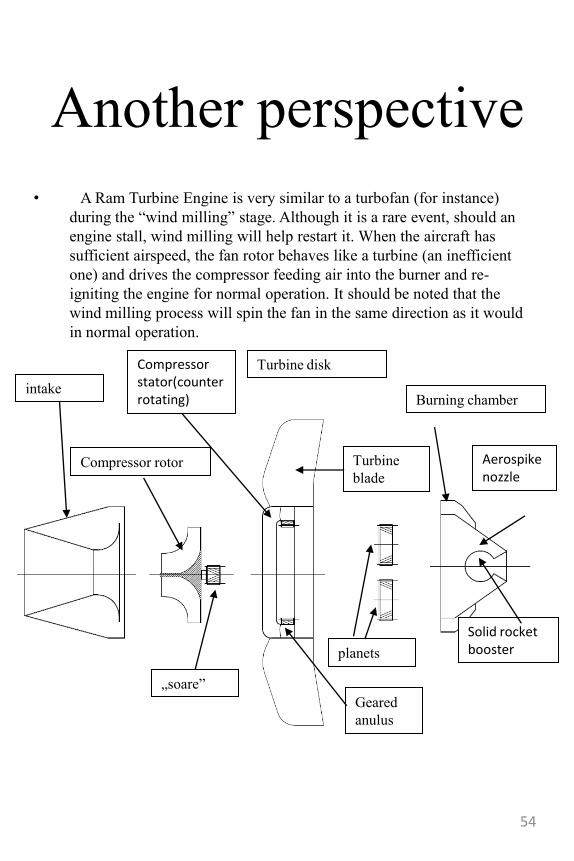
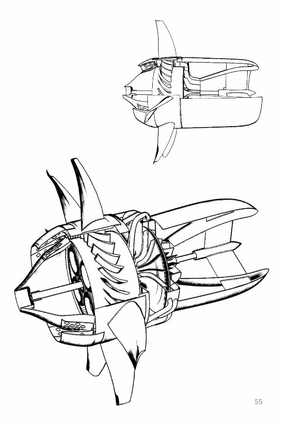
Another perspective
• A Ram Turbine Engine is very similar to a turbofan (for instance)
during the “wind milling” stage. Although it is a rare event, should an
engine stall, wind milling will help restart it. When the aircraft has
sufficient airspeed, the fan rotor behaves like a turbine (an inefficient
one) and drives the compressor feeding air into the burner and re-
igniting the engine for normal operation. It should be noted that the
wind milling process will spin the fan in the same direction as it would
in normal operation.
Compressor rotor
Turbine disk
Burning chamber
Aerospikenozzle
Solid rocket booster
Turbine
blade
planets
„soare”
intake
Compressor stator(counter rotating)
Geared
anulus
54
55
Other variations on the
ram turbojet
• -the gyrocopter study
• -the anemometric turbo-jet
configurations
• -the slim, variable pitch
ram air turbine jet engine
56
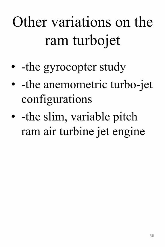
The gyrocopter study• This engine uses the main rotor of the
gyrocopter as a turbine that drives a compressor (in this case double centrifugal) trough a planetary gear system. (top-electro-motor system; bottom direct gear system)
57
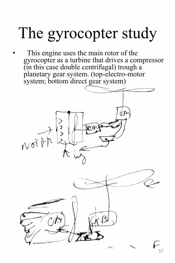
The gearing study
58
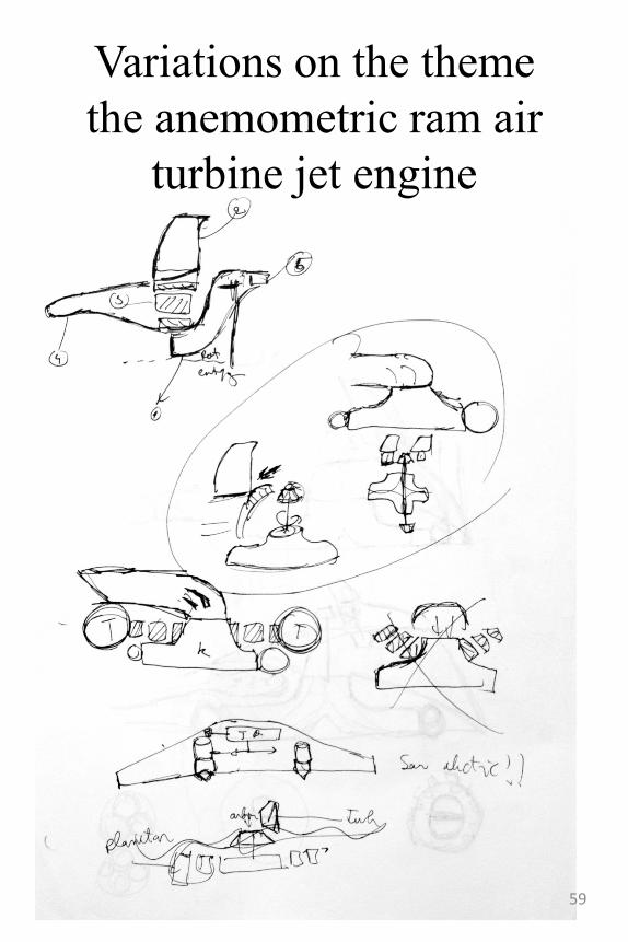
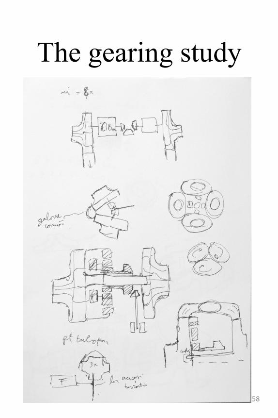
Variations on the theme
the anemometric ram air
turbine jet engine
59
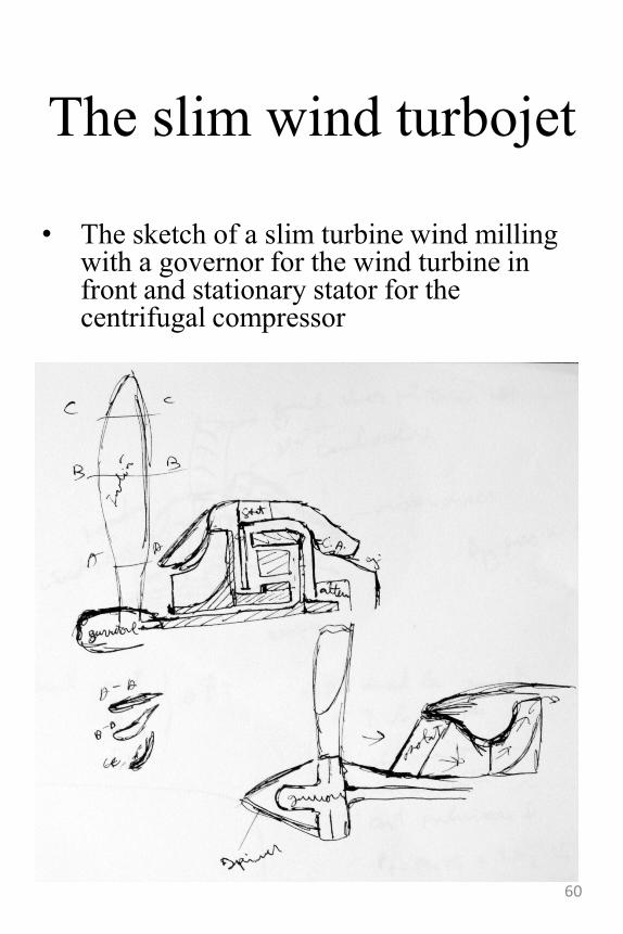
The slim wind turbojet
• The sketch of a slim turbine wind milling with a governor for the wind turbine in front and stationary stator for the centrifugal compressor
60
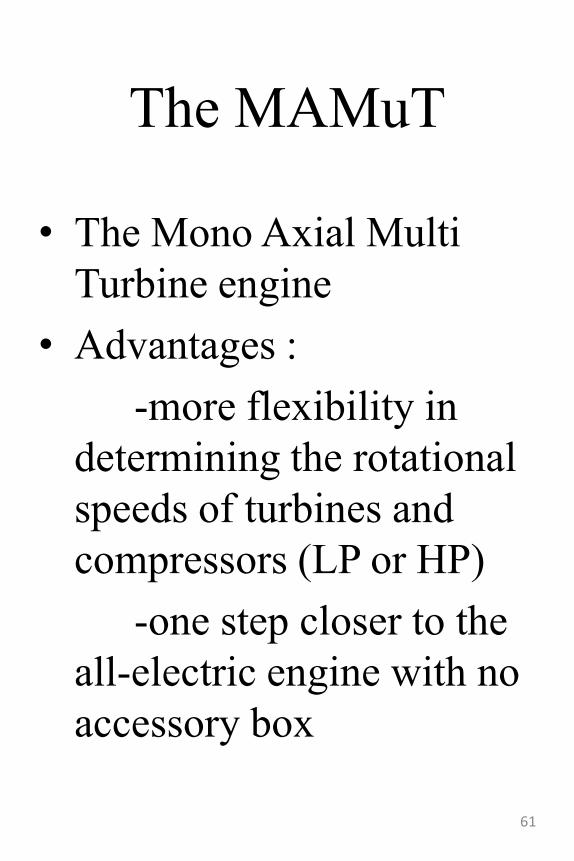
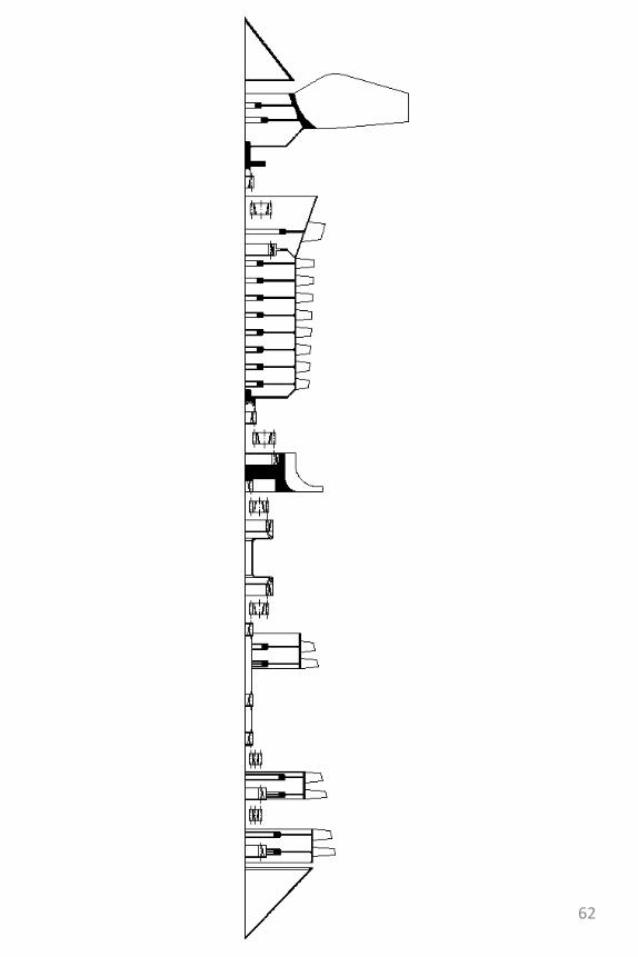
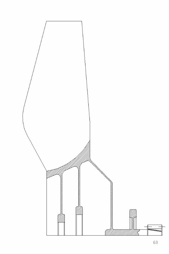
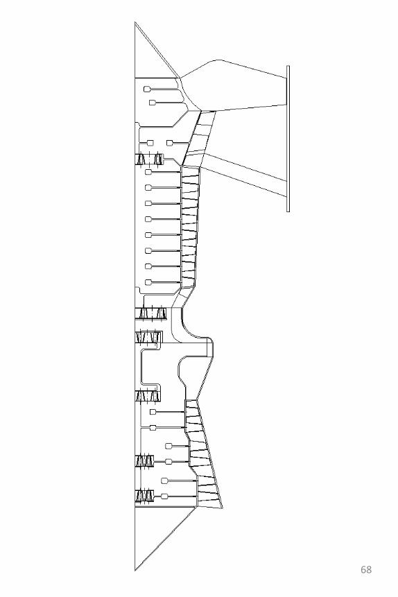
The MAMuT
• The Mono Axial Multi
Turbine engine
• Advantages :
-more flexibility in
determining the rotational
speeds of turbines and
compressors (LP or HP)
-one step closer to the
all-electric engine with no
accessory box
61
62
63
64
65
66
67
68
Taking the MAMuT
one step further
• A reasonable next step with this is to make a turbine engine that has a variable power delivery system, not unlike a gearbox. It would be really effective if it could shift power between the fan stage and the low pressure compressor.
• The benefits of such a system would be increased efficiency on a wider range of rpm/altitudes and also an increased flight envelope.
• For those benefits, a small price of additional weight and maintenance would have to be paid.
69
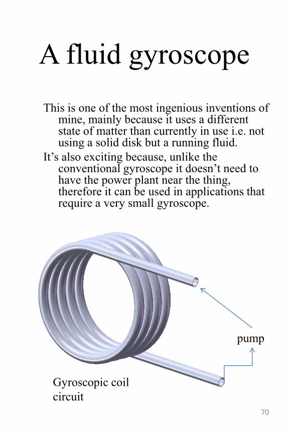
A fluid gyroscope
This is one of the most ingenious inventions of mine, mainly because it uses a different state of matter than currently in use i.e. not using a solid disk but a running fluid.
It‟s also exciting because, unlike the conventional gyroscope it doesn‟t need to have the power plant near the thing, therefore it can be used in applications that require a very small gyroscope.
pump
Gyroscopic coil
circuit
70
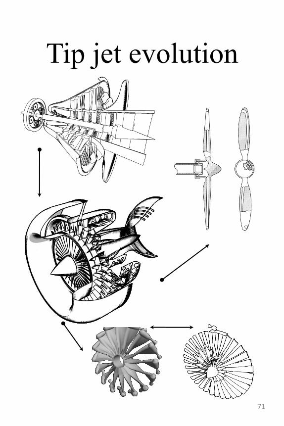
Tip jet evolution
71
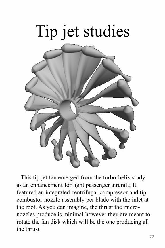
Tip jet studies
This tip jet fan emerged from the turbo-helix study
as an enhancement for light passenger aircraft; It
featured an integrated centrifugal compressor and tip
combustor-nozzle assembly per blade with the inlet at
the root. As you can imagine, the thrust the micro-
nozzles produce is minimal however they are meant to
rotate the fan disk which will be the one producing all
the thrust
72
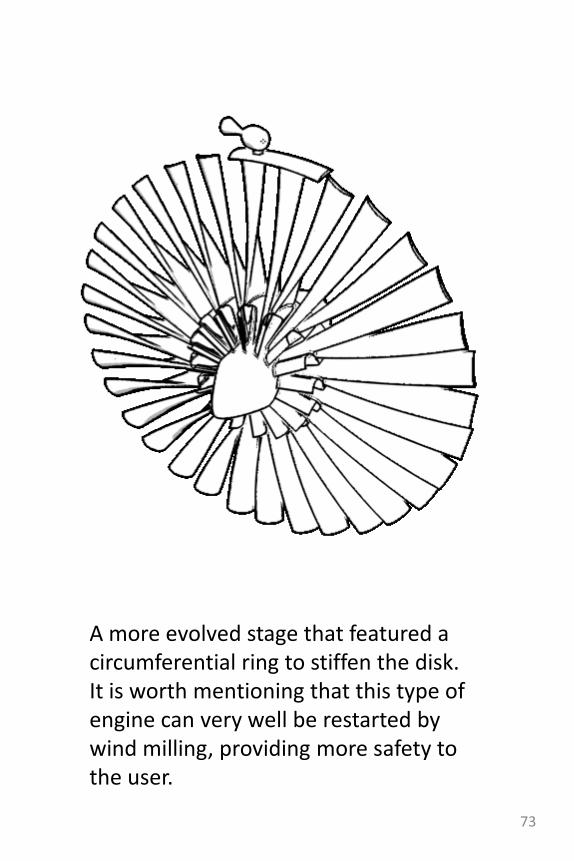
A more evolved stage that featured a circumferential ring to stiffen the disk.It is worth mentioning that this type of engine can very well be restarted by wind milling, providing more safety to the user.
73
Micro-turbine
propeller
• The mechanism of this engine is very similar-and in fact derived from- the ram air turbojet we‟ve seen earlier.
• What differentiates the two concepts is the kinematic scheme, i.e. in the MTP we have a gas turbine group that –in the end drives both the propeller and the compressor.
74
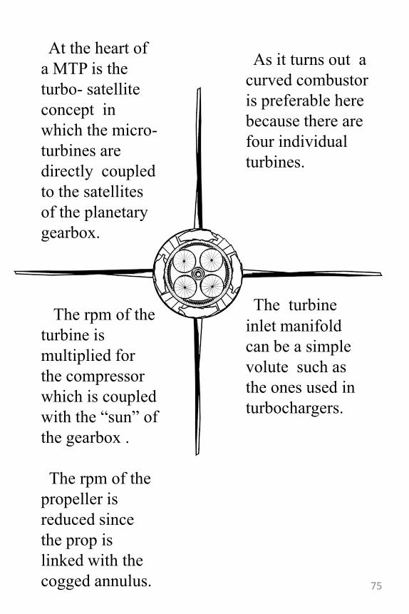
At the heart of
a MTP is the
turbo- satellite
concept in
which the micro-
turbines are
directly coupled
to the satellites
of the planetary
gearbox.
The rpm of the
turbine is
multiplied for
the compressor
which is coupled
with the “sun” of
the gearbox .
The rpm of the
propeller is
reduced since
the prop is
linked with the
cogged annulus.
As it turns out a
curved combustor
is preferable here
because there are
four individual
turbines.
The turbine
inlet manifold
can be a simple
volute such as
the ones used in
turbochargers.
75
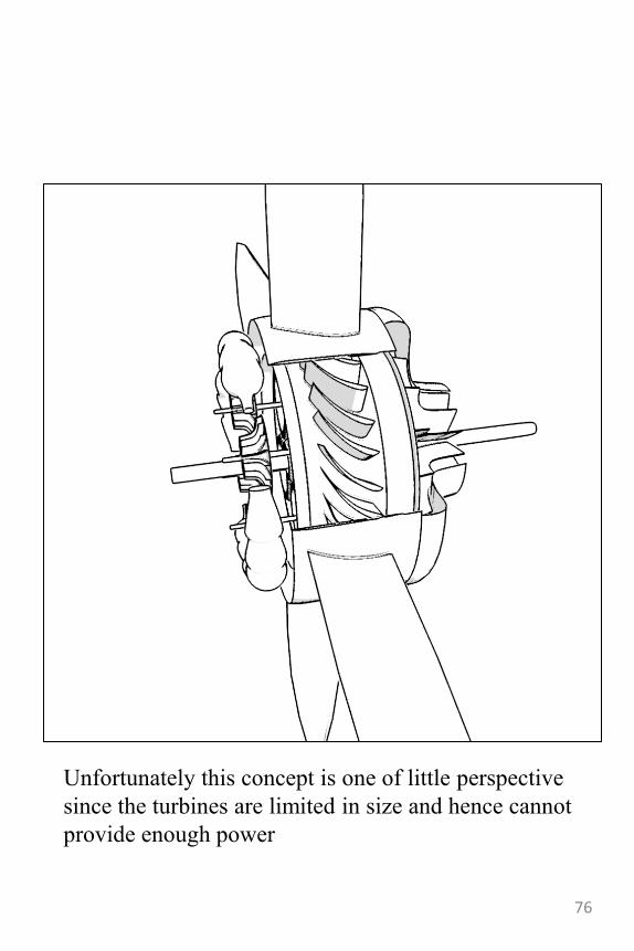
Unfortunately this concept is one of little perspective
since the turbines are limited in size and hence cannot
provide enough power
76
Hydrogen peroxide
power plant
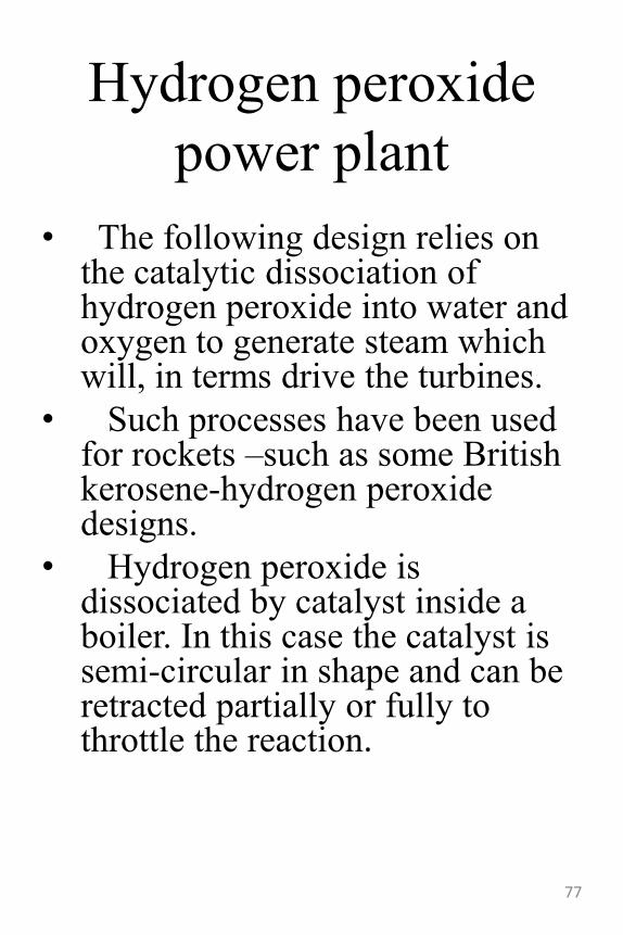
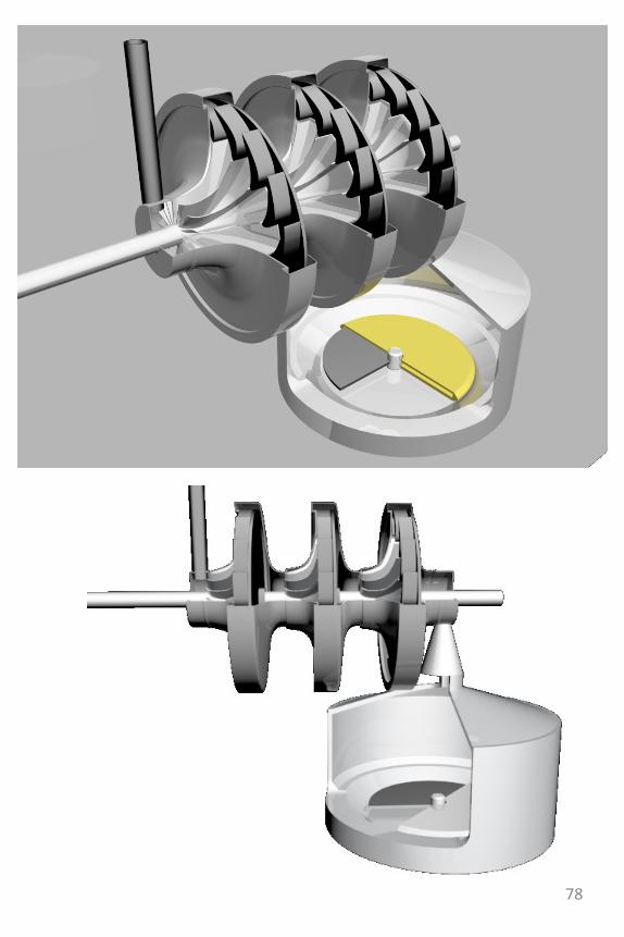
• The following design relies on the catalytic dissociation of hydrogen peroxide into water and oxygen to generate steam which will, in terms drive the turbines.
• Such processes have been used for rockets –such as some British kerosene-hydrogen peroxide designs.
• Hydrogen peroxide is dissociated by catalyst inside a boiler. In this case the catalyst is semi-circular in shape and can be retracted partially or fully to throttle the reaction.
77
78
Nuclear Turbofans• Nuclear jet engines have been the dream of many
engineers and physicists. Unfortunately the only
branch of society which actually invested in the
development of such engines was the military.
• Conventional military nuclear jet designs featured a
reactor-heater instead of a burning chamber leaving
the turbojet engine virtually unchanged in it‟s other
parts.
• This proved to be doomed to failure since there is no
such airplane flying at this time.
• The key to making such engines fly is not by using a
Brayton cycle but by using a Rankine cycle. The two,
very similar cycles are used for jet engines and
ground power plants respectively.
• The Rankine cycle, in my opinion, is ideal for this
nuclear engine because of one key feature: efficiency,
i.e. we will be using more power from the nuclear
reactor than we would if we were to use the Brayton
cycle. It is true there will have to be a closed circuit
with big heat exchangers but those can be neatly
integrated around the structure of the turbofan itself.
One more thing, because we‟re using a Rankine cycle
we shall be using a turbofan configuration which is
also more efficient than the turbojet-as proved by the
airliner industry.79
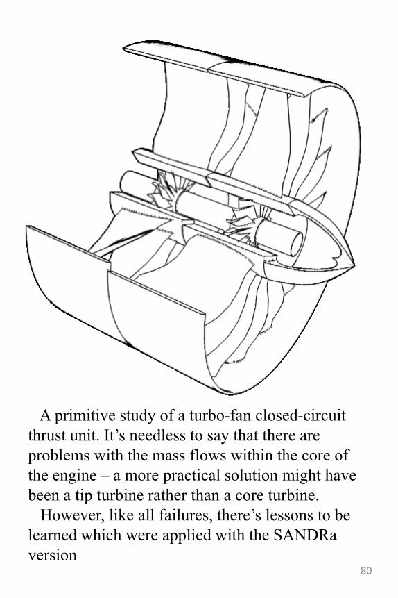
A primitive study of a turbo-fan closed-circuit
thrust unit. It‟s needless to say that there are
problems with the mass flows within the core of
the engine – a more practical solution might have
been a tip turbine rather than a core turbine.
However, like all failures, there‟s lessons to be
learned which were applied with the SANDRa
version80
81
SANDRa
• Sursa de Aviatie Nucleara Dublucircuit Rankine
• It‟s one of the two major examples of how you can under-think an invention. The lesson I should‟ve applied is that it‟s always simpler to focus on the true purpose of your invention and not try make smaller steps in between (see the hovercraft design)
• This new engine is a more viable solution for using a Rankine cycle to drive a turbofan.
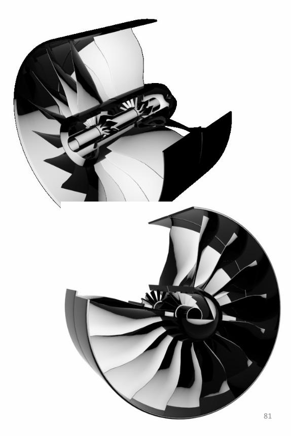
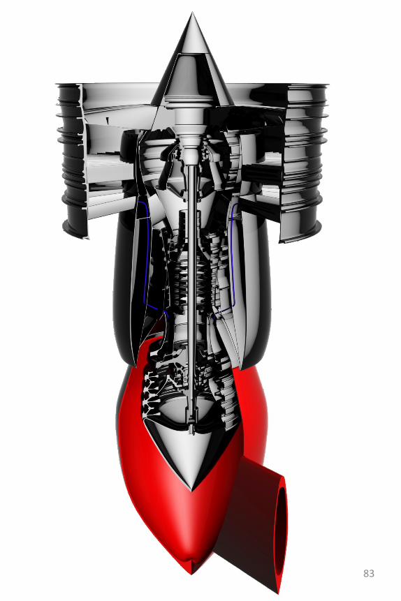
• The 3D renderings you can see however are the intermediate version of it. That is, with a burning chamber to provide the heat for the heat exchanger instead of just nuclear rods.
• This is one way a good idea gets lost because the intermediate version is even more challenging to engineer than the nuclear one. Such problems are: stoichiometricburning, air compression and powering trough the turbine from the Rankine cycle – which is really denying the point of having a Rankine cycle. The Rankine cycle is brilliant because it condenses the working fluid after it exits the turbine so that there is no need for a gas compressor (which The major consumer of power in a turbine engine) –it‟s true it still needs a pump instead of a compressor but the work needed to drive it is really negligible.
82
83
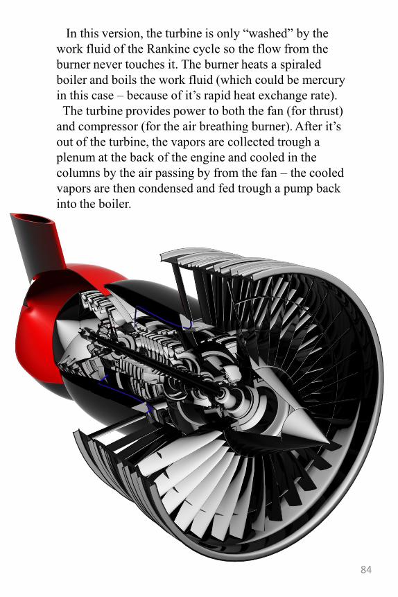
In this version, the turbine is only “washed” by the
work fluid of the Rankine cycle so the flow from the
burner never touches it. The burner heats a spiraled
boiler and boils the work fluid (which could be mercury
in this case – because of it‟s rapid heat exchange rate).
The turbine provides power to both the fan (for thrust)
and compressor (for the air breathing burner). After it‟s
out of the turbine, the vapors are collected trough a
plenum at the back of the engine and cooled in the
columns by the air passing by from the fan – the cooled
vapors are then condensed and fed trough a pump back
into the boiler.
84
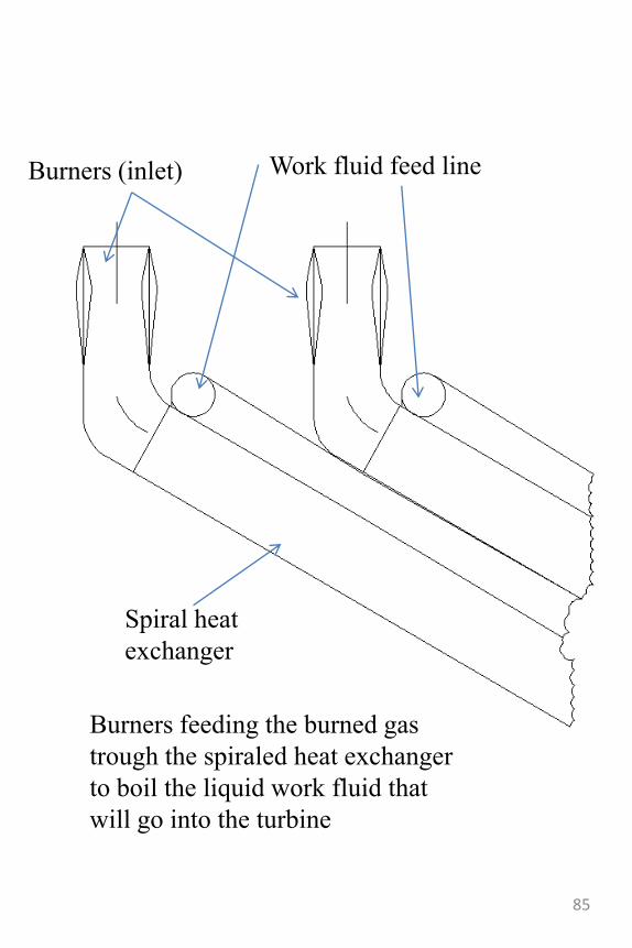
Burners feeding the burned gas
trough the spiraled heat exchanger
to boil the liquid work fluid that
will go into the turbine
Burners (inlet) Work fluid feed line
Spiral heat
exchanger
85
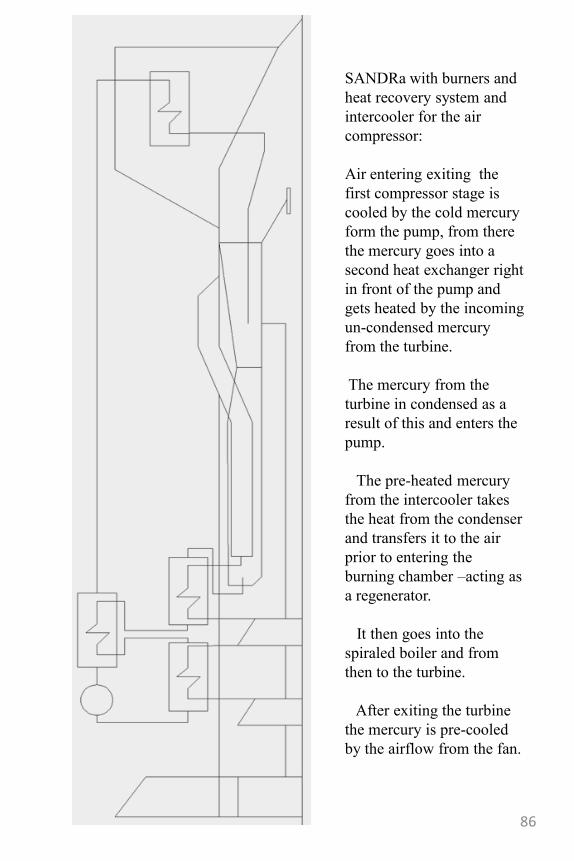
SANDRa with burners and
heat recovery system and
intercooler for the air
compressor:
Air entering exiting the
first compressor stage is
cooled by the cold mercury
form the pump, from there
the mercury goes into a
second heat exchanger right
in front of the pump and
gets heated by the incoming
un-condensed mercury
from the turbine.
The mercury from the
turbine in condensed as a
result of this and enters the
pump.
The pre-heated mercury
from the intercooler takes
the heat from the condenser
and transfers it to the air
prior to entering the
burning chamber –acting as
a regenerator.
It then goes into the
spiraled boiler and from
then to the turbine.
After exiting the turbine
the mercury is pre-cooled
by the airflow from the fan.
86
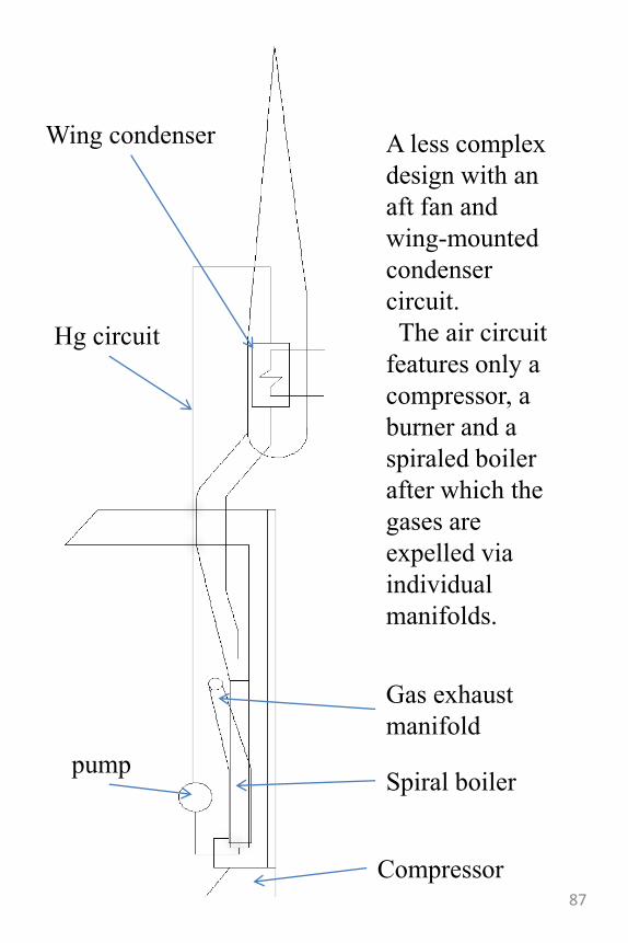
A less complex
design with an
aft fan and
wing-mounted
condenser
circuit.
The air circuit
features only a
compressor, a
burner and a
spiraled boiler
after which the
gases are
expelled via
individual
manifolds.
Gas exhaust
manifold
Wing condenser
Hg circuit
pump
Compressor
Spiral boiler
87
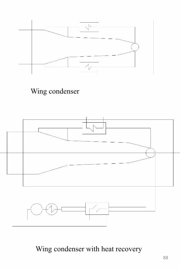
Wing condenser
Wing condenser with heat recovery 88
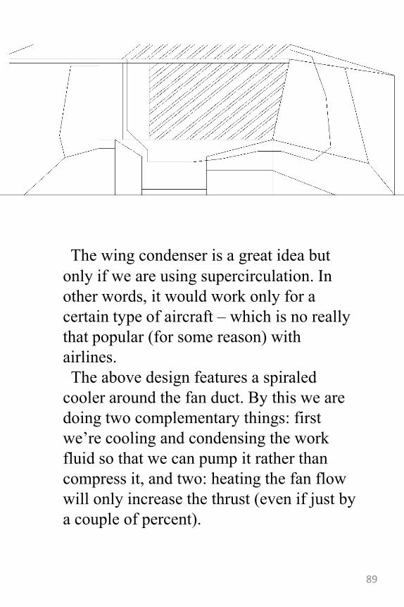
The wing condenser is a great idea but
only if we are using supercirculation. In
other words, it would work only for a
certain type of aircraft – which is no really
that popular (for some reason) with
airlines.
The above design features a spiraled
cooler around the fan duct. By this we are
doing two complementary things: first
we‟re cooling and condensing the work
fluid so that we can pump it rather than
compress it, and two: heating the fan flow
will only increase the thrust (even if just by
a couple of percent).
89
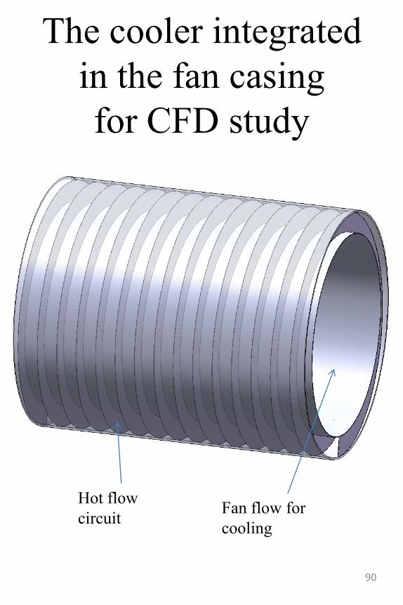
The cooler integrated
in the fan casing
for CFD study
90
Hot flow
circuit Fan flow for
cooling
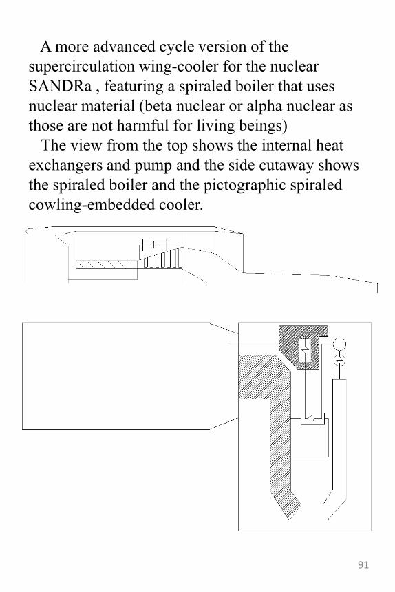
A more advanced cycle version of the
supercirculation wing-cooler for the nuclear
SANDRa , featuring a spiraled boiler that uses
nuclear material (beta nuclear or alpha nuclear as
those are not harmful for living beings)
The view from the top shows the internal heat
exchangers and pump and the side cutaway shows
the spiraled boiler and the pictographic spiraled
cowling-embedded cooler.
91
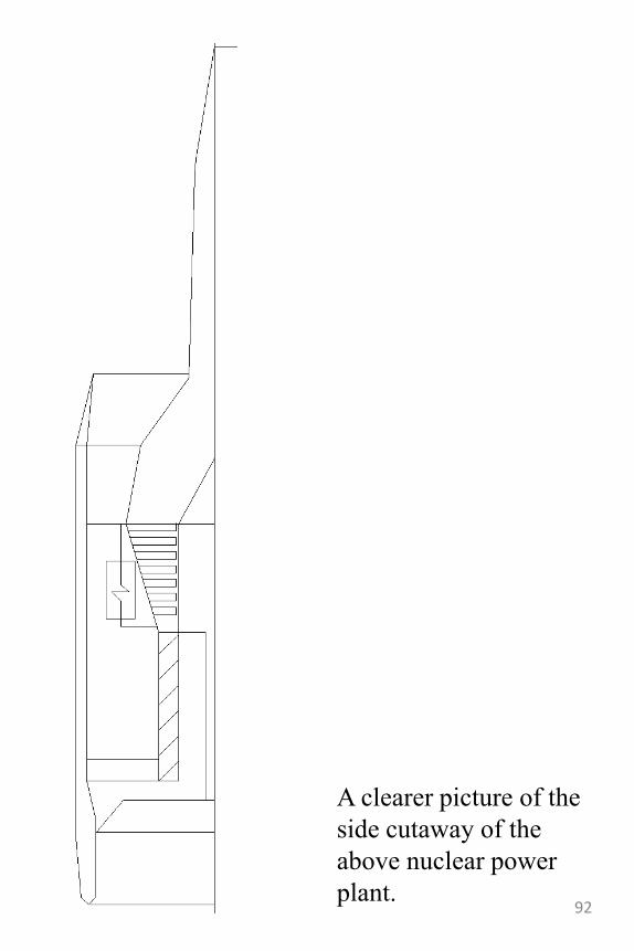
A clearer picture of the
side cutaway of the
above nuclear power
plant.92
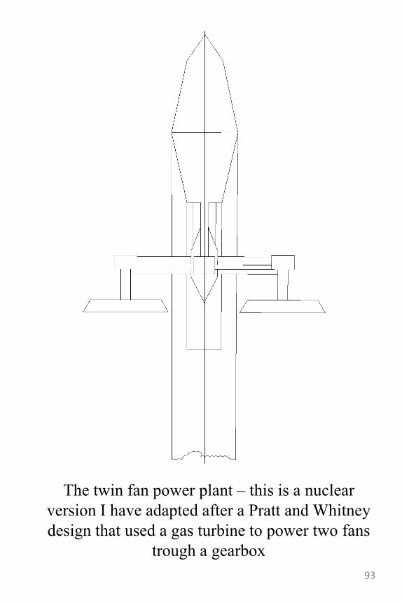
The twin fan power plant – this is a nuclear
version I have adapted after a Pratt and Whitney
design that used a gas turbine to power two fans
trough a gearbox
93
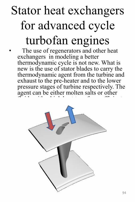
Stator heat exchangers
for advanced cycle
turbofan engines• The use of regenerators and other heat
exchangers in modeling a better thermodynamic cycle is not new. What is new is the use of stator blades to carry the thermodynamic agent from the turbine and exhaust to the pre-heater and to the lower pressure stages of turbine respectively. The agent can be either molten salts or other fluids with a high heat transfer coefficient such as mercury.
94
From A to C trough
B.5
• It‟s a cliché that inventors can go directly from A to C without passing trough B. I refute that, it‟s true that an inventor sees more than a non-inventor (if such persons exist..which I sincerely doubt) but that is not because he looks beyond, but rather because he‟s looking for something new. Usually they‟d spend time breaking the “objective” in smaller “atoms” and recomposing it to see what he gets.– In my brief experience as an engineer I
witnessed this discussion about designing a rudder for an UAV, the FSD team asked for a bigger rudder because the current one didn‟t deliver enough force. The aerodynamics team immediately agreed and started integrating the new requirement for the bigger rudder.
– Experience in this case short-circuited the solution to the problem without any thought process. In fact the problem wasn‟t the rudder at all (especially not it‟s size) but rather the fact that we needed a higher force. This could have been achieved in a lot of different ways for instance making it more efficient or using circulation control..
– The moral is to try and be aware of these short circuits and try to come back and just think for a second.
95
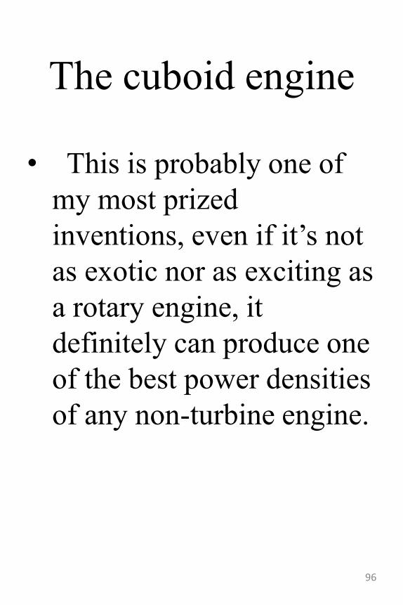
The cuboid engine
• This is probably one of
my most prized
inventions, even if it‟s not
as exotic nor as exciting as
a rotary engine, it
definitely can produce one
of the best power densities
of any non-turbine engine.
96
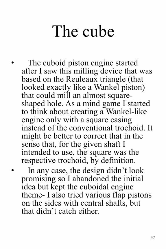
The cube
• The cuboid piston engine started after I saw this milling device that was based on the Reuleaux triangle (that looked exactly like a Wankel piston) that could mill an almost square-shaped hole. As a mind game I started to think about creating a Wankel-like engine only with a square casing instead of the conventional trochoid. It might be better to correct that in the sense that, for the given shaft I intended to use, the square was the respective trochoid, by definition.
• In any case, the design didn‟t look promising so I abandoned the initial idea but kept the cuboidal engine theme- I also tried various flap pistons on the sides with central shafts, but that didn‟t catch either.
97
98
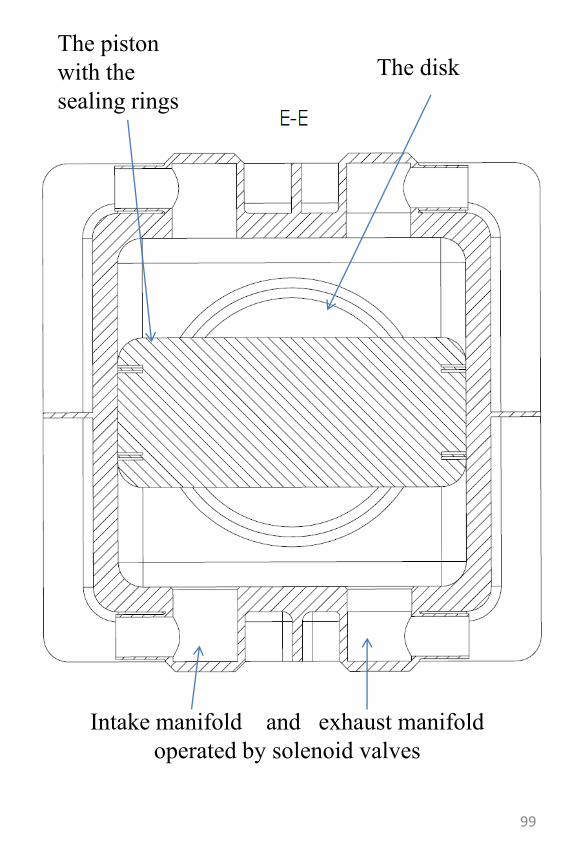
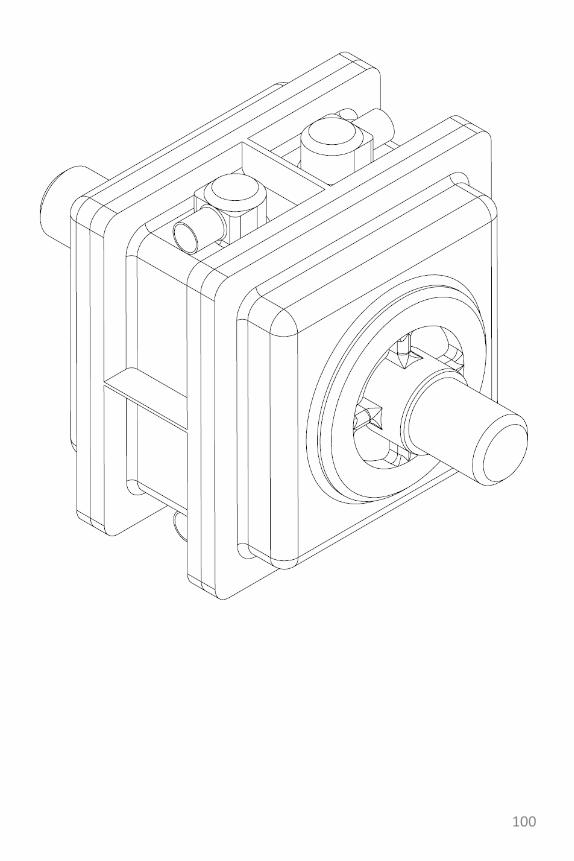
Intake manifold and exhaust manifold
operated by solenoid valves
The piston
with the
sealing rings
The disk
99
100
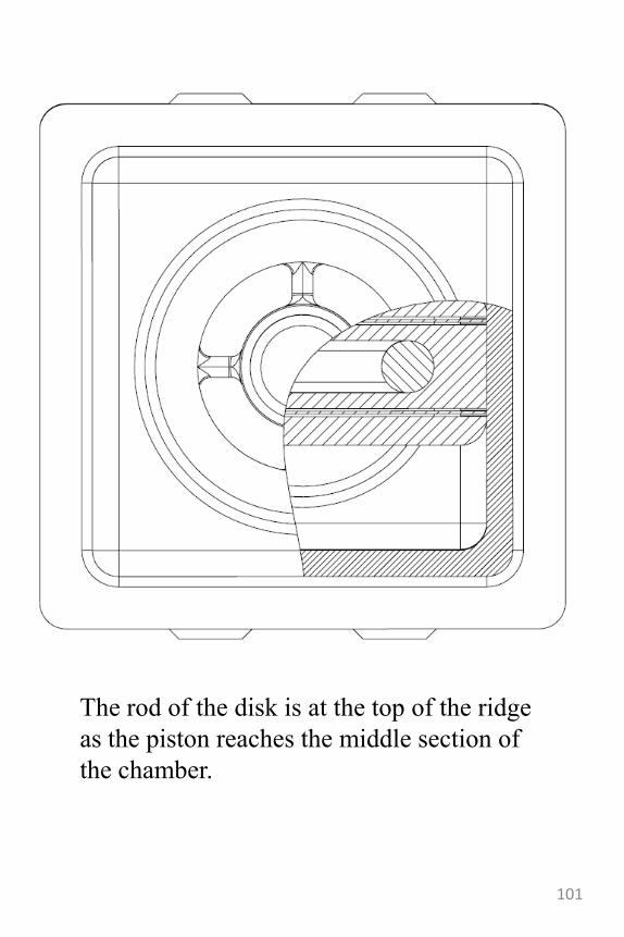
The rod of the disk is at the top of the ridge
as the piston reaches the middle section of
the chamber.
101
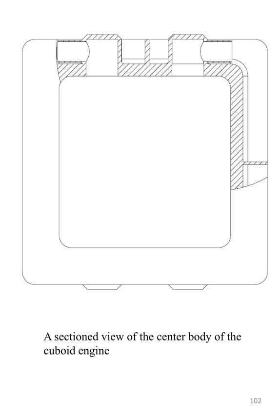
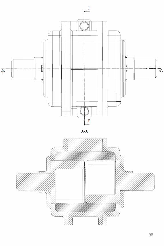
A sectioned view of the center body of the
cuboid engine
102
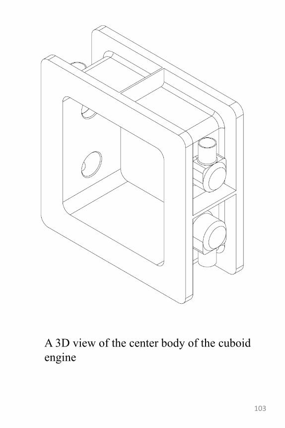
A 3D view of the center body of the cuboid
engine
103
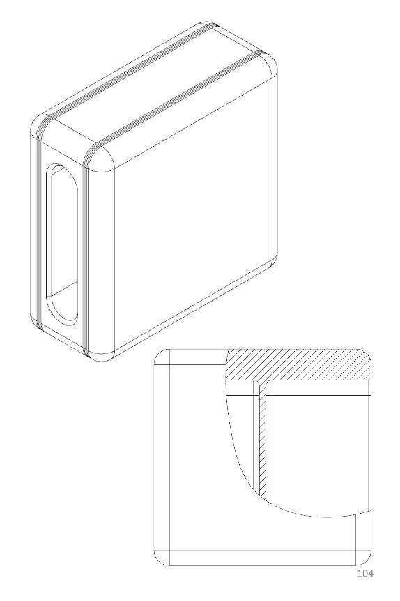
104
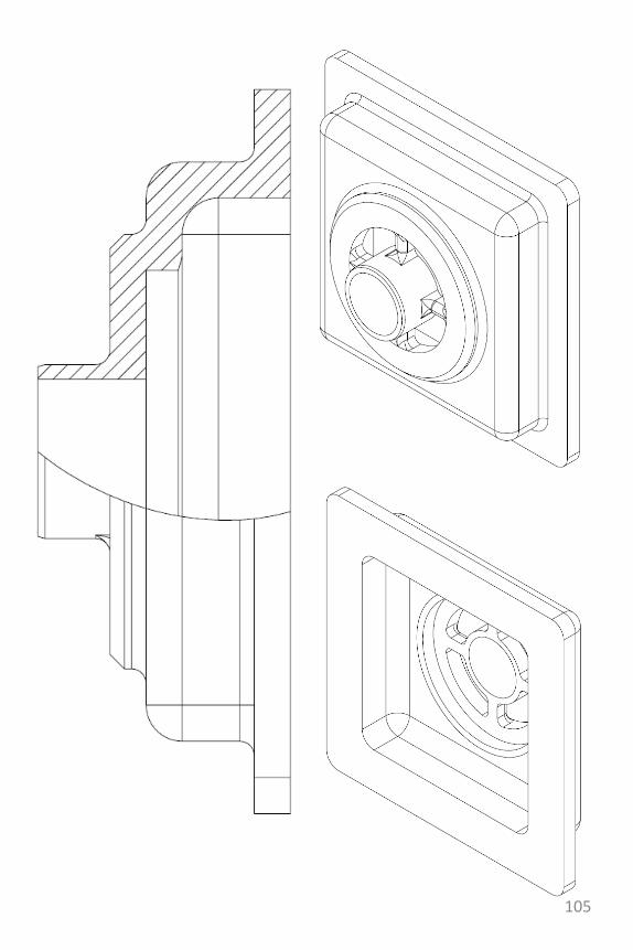
105
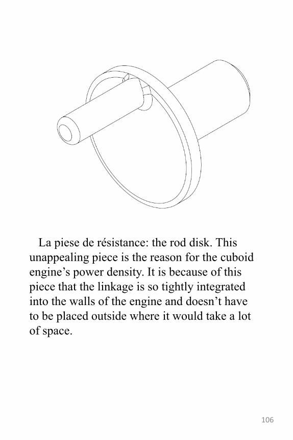
La piese de résistance: the rod disk. This
unappealing piece is the reason for the cuboid
engine‟s power density. It is because of this
piece that the linkage is so tightly integrated
into the walls of the engine and doesn‟t have
to be placed outside where it would take a lot
of space.
106
The cuboid engine
with hyper modularity
• The quad-cuboidal engine is somewhat an over-
stretched version of the cuboid piston engine.
• After sorting out the scotch yoke integration within
the engine walls, I started experimenting with
different configurations, one of which was a two
stroke engine (which I abandoned after realizing that
in the normal configuration the cuboid engine did
already work similar to a two stroke engine).
• Another idea was to make use of the modularity of
the engine which allowed for two or more engines to
be coupled together-producing more power. This was
good on one axis but it still felt like it could be more
to it than that.
• The addition of another scotch yoke linkage on the
other axis of the piston brought with it the possibility
to create a completely new form of modularity: a 3D
modular engine.
• Because of the 3D modularity, this version could
really be made to slim-fit into any engine
compartment regardless of the shape, bearing in mind
that there still has to be some sort of strength to the
components and that there may be other limitations to
the system..107
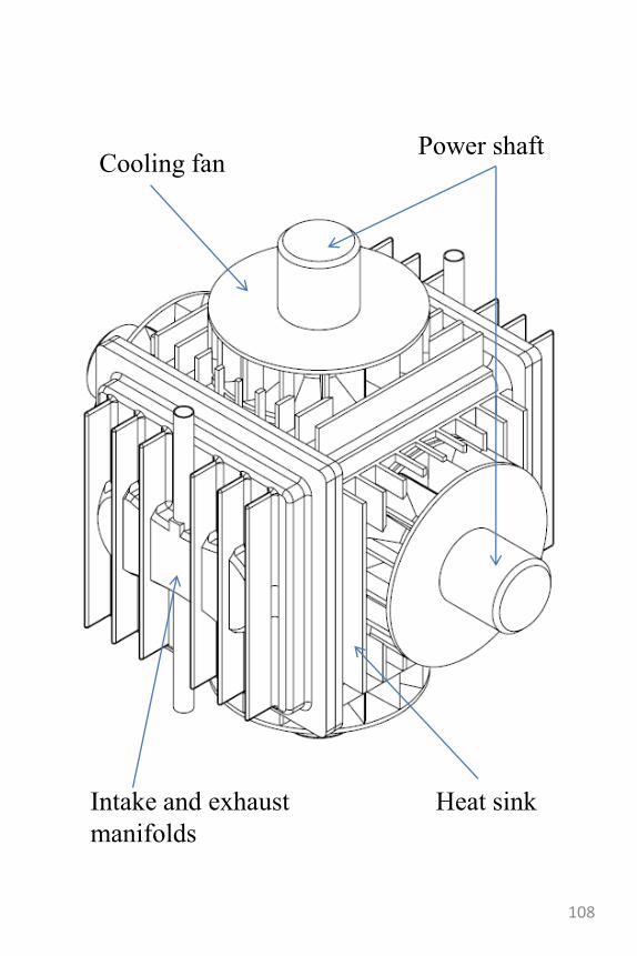
Intake and exhaust
manifolds
Cooling fanPower shaft
Heat sink
108
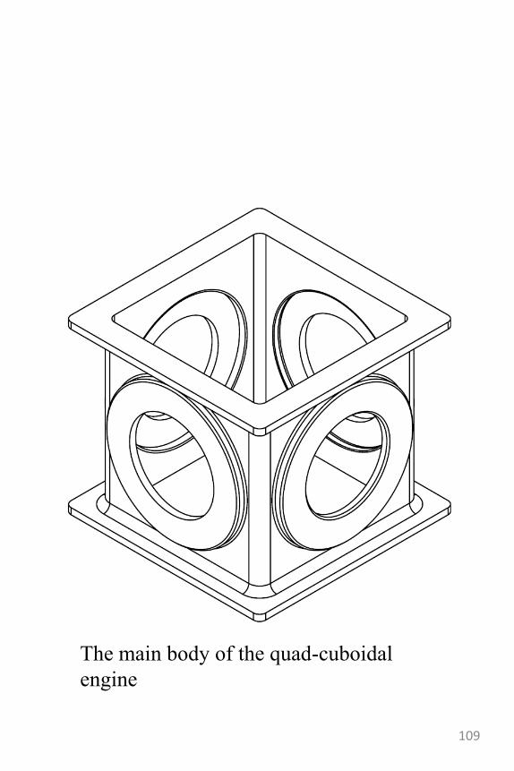
The main body of the quad-cuboidal
engine
109
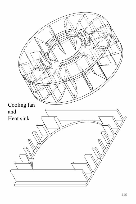
Cooling fan
and
Heat sink
110
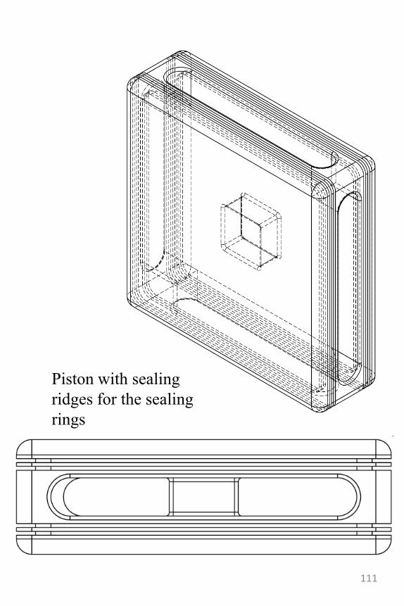
Piston with sealing
ridges for the sealing
rings
111
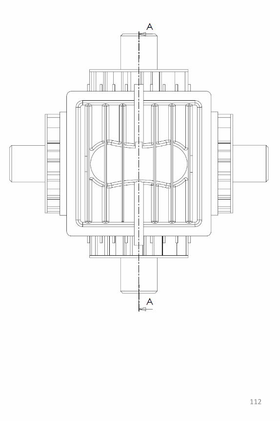
112
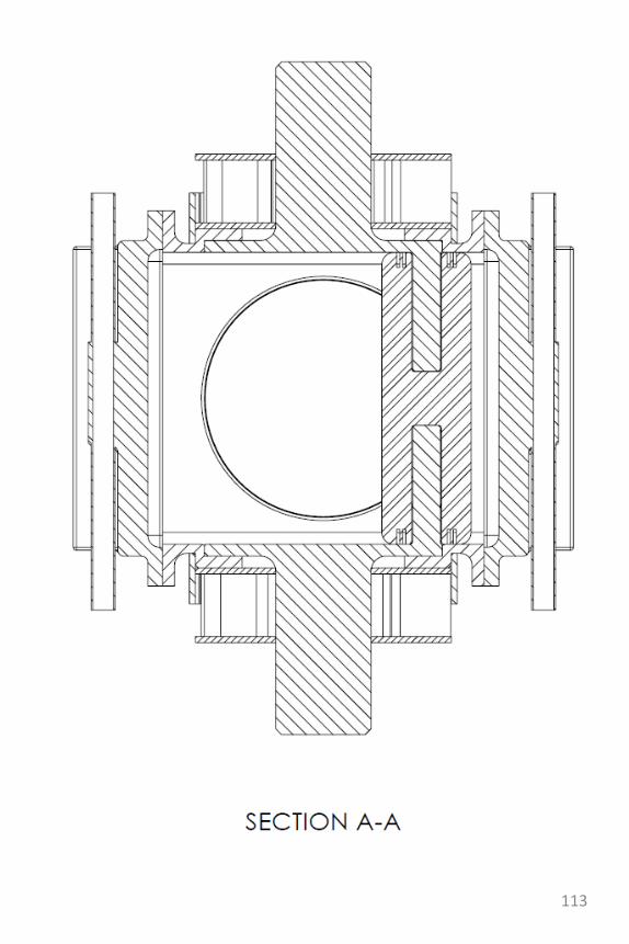
113
114
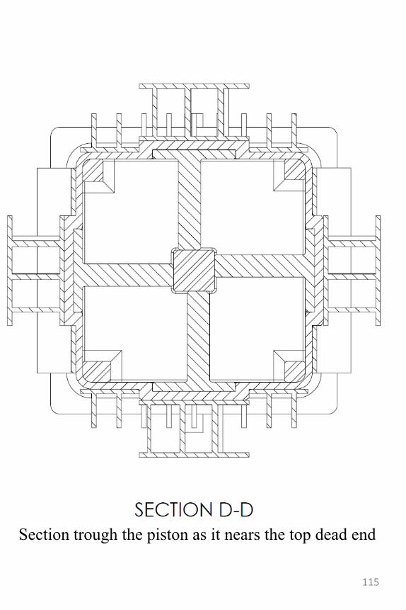
Section trough the piston as it nears the top dead end
115
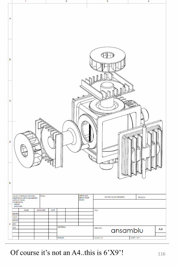
Of course it‟s not an A4..this is 6‟X9‟! 116
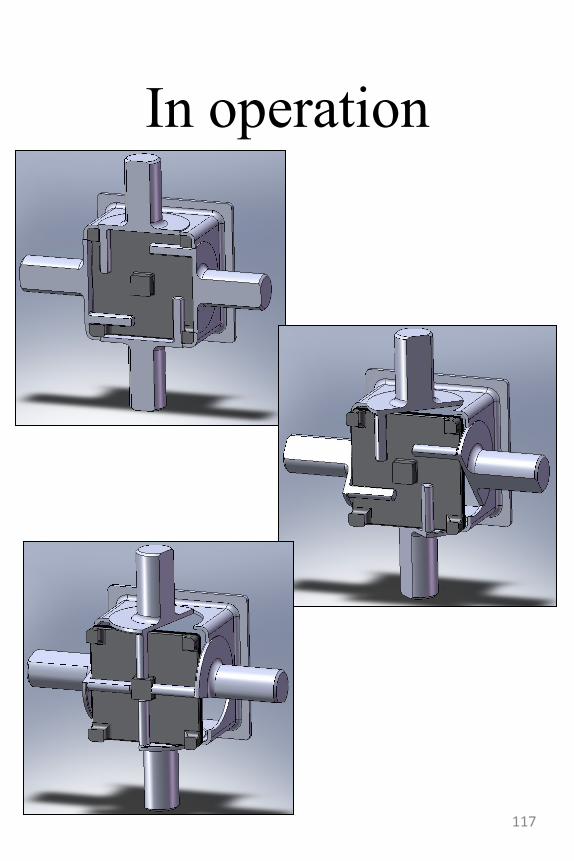
In operation
117
Other considerations
regarding the cuboid
engine• The sealing of the piston as it
passes by the disk has been a major design problem. The solutions used are:
– The chamfering of the disk and it‟s wall
– The use of intermediate oblique holders for the sealing rings. The oblique holders are designed to “attach” the ridges between the disk and the wall perpendicular to the disk circumference (i.e. radial to the point of contact) so as to minimize wear and drag.
118
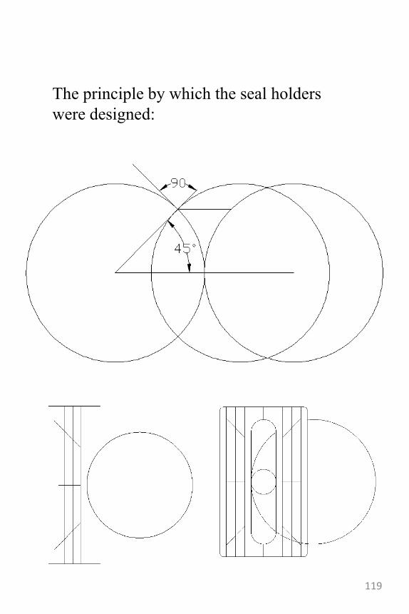
The principle by which the seal holders
were designed:
119
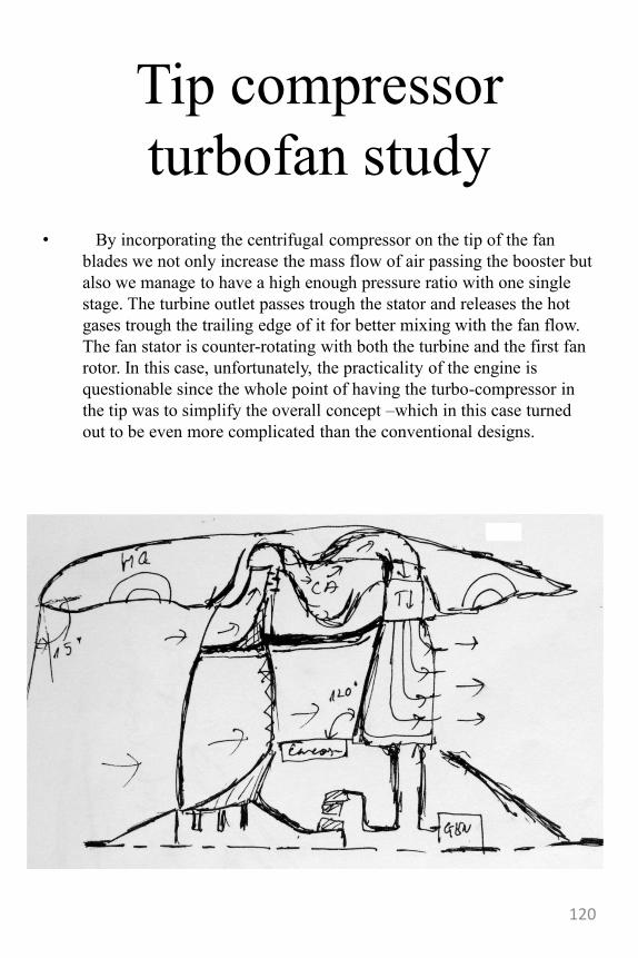
Tip compressor
turbofan study
• By incorporating the centrifugal compressor on the tip of the fan
blades we not only increase the mass flow of air passing the booster but
also we manage to have a high enough pressure ratio with one single
stage. The turbine outlet passes trough the stator and releases the hot
gases trough the trailing edge of it for better mixing with the fan flow.
The fan stator is counter-rotating with both the turbine and the first fan
rotor. In this case, unfortunately, the practicality of the engine is
questionable since the whole point of having the turbo-compressor in
the tip was to simplify the overall concept –which in this case turned
out to be even more complicated than the conventional designs.
120
The semi-pressurized
burner turbofan• This design tries to by-pass the need for a turbo-
compressor using instead an integrated turbine.
• The blades are very similar to the turbo-helix but
with the added feature of the casing for collecting the
exhaust gas and directing it to the stator for cooling.
• Thermodynamically, the engine can run either on
Brayton or Rankine cycles. The stator has three
cooling passages that return the gas from the
integrated turbine to the plenum and from that to the
hot circuit surrounding the combustion chamber.
• A single combustor is used in conjunction with a
ram intake –hence the name “semi compressed”. The
engine will also require a pump to take input the cool
gas back into the heating coil.
• As a remark, it is clear that this engine will work
should everything be dimensioned properly however
the power output will be smaller than usual due to the
fact that the mass flow of air is smaller and so we can
only burn a smaller amount of fuel to extract energy.
• However there is potential for a nuclear application
since the nuclear material will have an output of heat
independent of the mass flow of air.
121
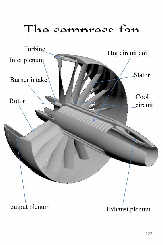
The sempress fan
Exhaust plenum
Inlet plenum
output plenum
Burner intake
Hot circuit coil
Stator
Rotor Cool
circuit
Turbine
122
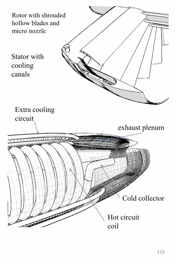
Stator with
cooling
canals
Rotor with shrouded
hollow blades and
micro nozzle
Extra cooling
circuit
exhaust plenum
Cold collector
Hot circuit
coil
123
Supercirculation vs.
countercirculation
• A failure can always be a blessing in disguise.
•
• Working on a supercirculation divertlessthrust vectoring nozzle I stumbled upon the fact that the surfaces I expected to provide a positive force actually produced a negative one. This was because the increase of the static pressure was more than compensated by the total pressure of the jet-so the static pressure never decreased below the ambient pressure.
• For someone who is open minded this should have been an instant revelation-the counter circulation principle. Well, not for me, I believed in the supercirculation effect so much that the failure to achieve it blinded me, and so it was not until I managed to make it work my way that I actually had the revelation that it could have gone the other way also.. I immediately started studying this other principle and designed a mixed circulation nozzle that outperformed the first by far.
124
The Maximal Attitude
Immediate Response
Actuator• One of my latest inventions is this new
kind of thrust vectoring unit. It‟s one of those typical moments when you‟re completely focused on something else and the breakthrough pops out of nothing. It‟s true that I had been studying supercirculation for almost two years at that time but this never occurred to me even if it‟s so simple almost anyone else would have seen it from the beginning.
• The principle is simple: use supercirculation to create “lift” on a surface that is surrounding the nozzle. The resulting force will act upon the entire airframe and vector the aircraft. The catch is-and this is a big one-that the flow remains virtually un-diverted so that the result is a very spectacular (and potentially dangerous) maneuver: the turning of the aircraft with the front to the back (tète-a-cue)
125
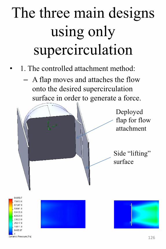
The three main designs
using only
supercirculation• 1. The controlled attachment method:
– A flap moves and attaches the flow
onto the desired supercirculation
surface in order to generate a force.
Side “lifting”
surface
Deployed
flap for flow
attachment
126
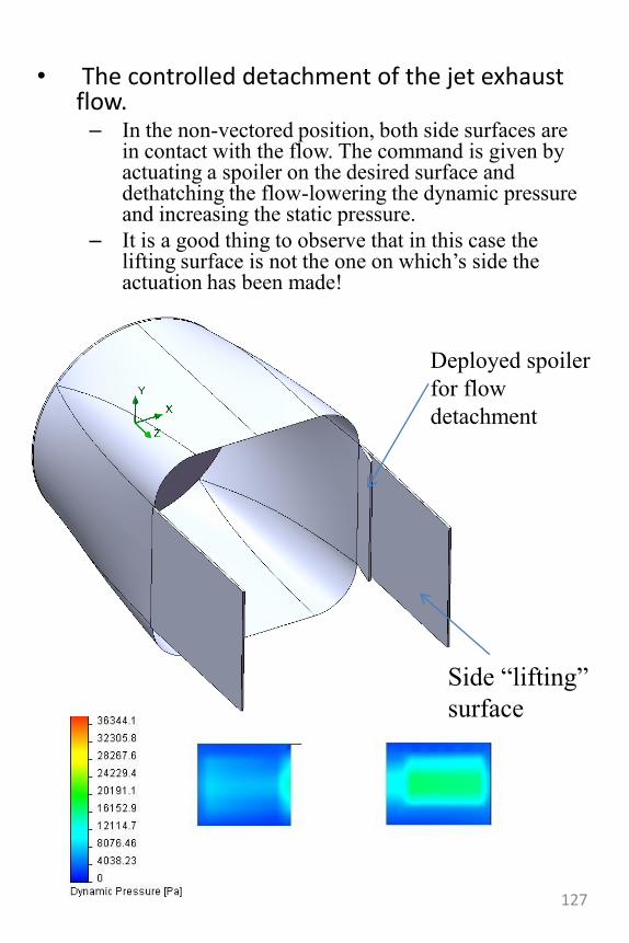
• The controlled detachment of the jet exhaust flow.– In the non-vectored position, both side surfaces are
in contact with the flow. The command is given by actuating a spoiler on the desired surface and dethatching the flow-lowering the dynamic pressure and increasing the static pressure.
– It is a good thing to observe that in this case the lifting surface is not the one on which‟s side the actuation has been made!
Deployed spoiler
for flow
detachment
Side “lifting”
surface
127
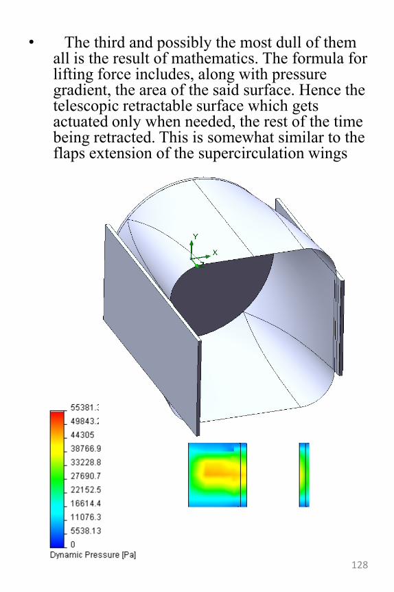
• The third and possibly the most dull of them all is the result of mathematics. The formula for lifting force includes, along with pressure gradient, the area of the said surface. Hence the telescopic retractable surface which gets actuated only when needed, the rest of the time being retracted. This is somewhat similar to the flaps extension of the supercirculation wings
128
The Rhino Chevron
-and diamond canards-• Chevrons are vortex generator devices aiming to
decrease the jet mixing noise in jet engine exhaust.
They work by promoting longitudinal vortices and
mixing the two adjacent flows so that they defuse the
Kelvin-Helmholtz phenomenon that causes the noise.
• So far so good.. The problem with chevrons is that
they are great energy consumers and this is one of the
reasons why they are not as common today (even if
they have been invented decades ago).
• Studying chevrons in CFD revealed the source of
their aerodynamic loss: two symmetrical vortices
emerging from the upper surface and feeding each
other so that in the end they consumed a lot of kinetic
energy, slowing down the flow near by.
• The immediate solution was to insert a separating
wall right between the two and try and contain them
so that, at least, they won‟t be feeding each other.
• It was with great surprise that I realized the
phenomenon almost disappeared immediately after
the wall was introduced.
• Luck sometimes works in our favor so a result such
as this is better than we‟ve expected. In the end, the
aerodynamic losses were reduced seven folds!
129
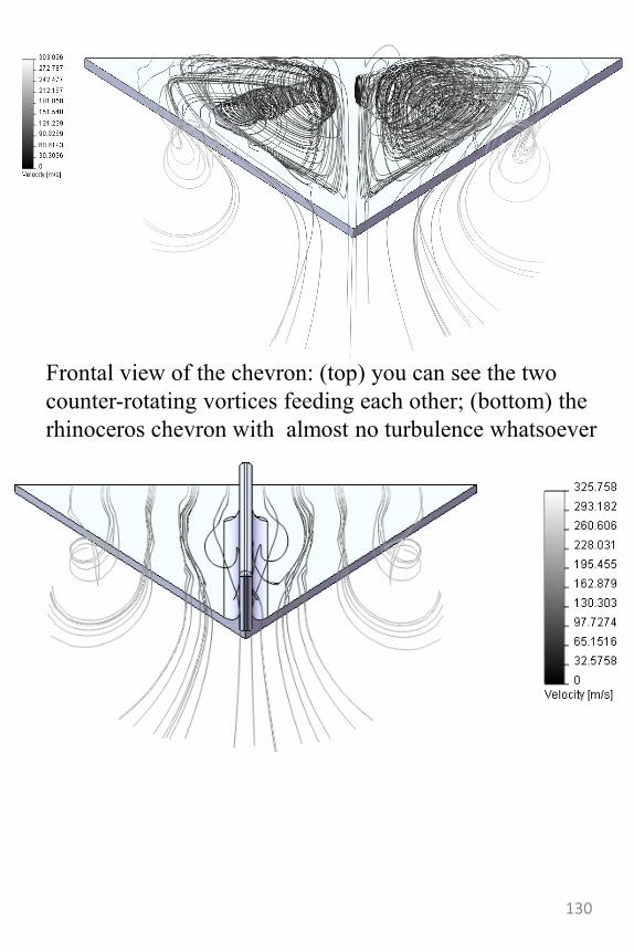
Frontal view of the chevron: (top) you can see the two
counter-rotating vortices feeding each other; (bottom) the
rhinoceros chevron with almost no turbulence whatsoever
130
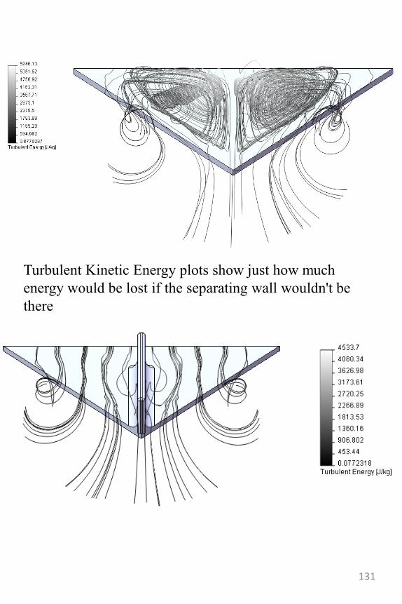
Turbulent Kinetic Energy plots show just how much
energy would be lost if the separating wall wouldn't be
there
131
132
133
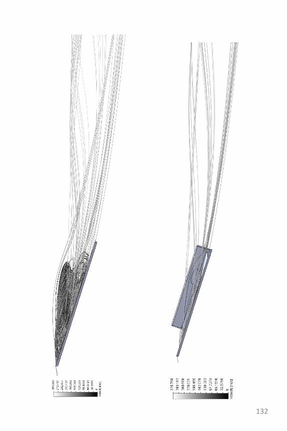
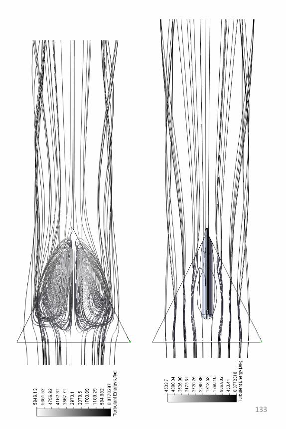
The negative delta wing
and diamond canards
• There are three major wing configurations to date: the classical wing with a high aspect ratio be it with positive or negative sweep, delta wings and reverse delta wings.
• The delta wing generates two counter rotating vortices that generate low static pressure on top of the wings-hence generating lift.
134
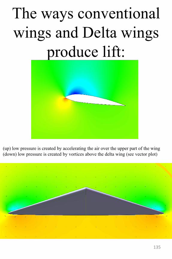
The ways conventional
wings and Delta wings
produce lift:
(up) low pressure is created by accelerating the air over the upper part of the wing
(down) low pressure is created by vortices above the delta wing (see vector plot)
135
The negative delta
• As everybody knows by now, airliners, fighter planes and so on either use conventional wings or delta wings but how about reverse delta wings? Those are also used but for a less known type of aircraft: the ekranoplane, named after the ground effect used to generate lift. Apart for that, the reverse delta hasn‟t been used much mainly because at high angles of attack it generates the same vortices we‟ve seen forming on chevrons.
• So this is our connection, if we could transpose the lessons learned with chevrons to reverse delta wings maybe we could design aircraft that fly both as ekranoplanes and as conventional aircraft at high altitudes and being able to make normal maneuvers.
136
Diamond canards
• And at last, we reach the diamond canards: they are formed by sticking a regular delta to a reverse delta canard with the effect that they generate a downstream vortex not unlike the ones a delta wing would create. Only this time the vortex is generated by the much smaller surface of the canard so that we don‟t really need a delta wing to create it‟s own vortex-hence a new principle of flying (with the mention that canards have been used in conjunction with delta wings to augment lift for decades, however in this case, the diamond canards are working with a non delta wing that behaves like a delta because of the diamond canards).
137
On their own
and on the aircraft
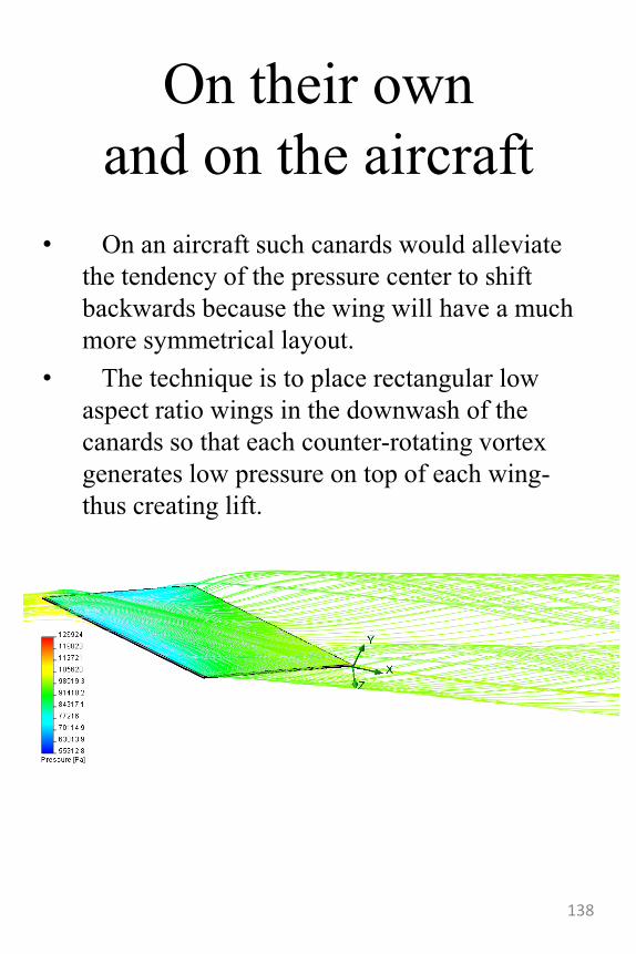
• On an aircraft such canards would alleviate
the tendency of the pressure center to shift
backwards because the wing will have a much
more symmetrical layout.
• The technique is to place rectangular low
aspect ratio wings in the downwash of the
canards so that each counter-rotating vortex
generates low pressure on top of each wing-
thus creating lift.
138
The “hovy”
• Previously we‟ve seen how, on my own, I under-developed a nuclear engine study that was going well and turned it into a combustion engine complicating things uselessly.
• On this occasion, which was chronologically before the nuclear engine, I was asked to design “at least five intermediate steps” because my proposal was too different form the original designs of the person who managed this project. The use of italics, is in order to save space and should not be interpreted as an irony.
139
The attitude vectoring
concepts:
• 2D thrust vectoring
(classic)
• Inertial plate controller
(similar to the ones used
on satellites)
• Nozzle swilling actuators
– Flexible integrated nozzles
– Profiled tri-nozzles
– Cylindrical tri-nozzles
140
2D vectoring vs. new
designs
• The classic designs has three major drawbacks:
• 1.The need for the drive fan to be working-i.e. the craft Must be moving, thus the turning radius is inherently great.
• 2.The Thrust force has an application center considerably above the center of gravity of the craft, thus the craft will have an inherent tendency to lean forward, posing a safety risk
• 3.The control surfaces must have a symmetric profile, thus the maximum angle of attack at which they can be positioned is limited. The profile studied in this paper was a NACA 0004, the max. angle was 12º
141
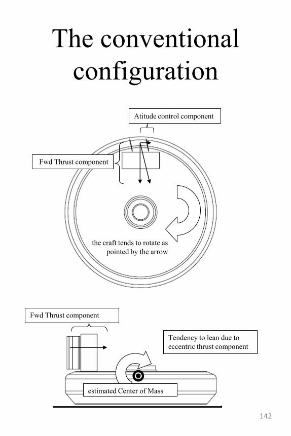
The conventional
configuration
Fwd Thrust component
estimated Center of Mass
Tendency to lean due to
eccentric thrust component
Atitude control component
Fwd Thrust component
the craft tends to rotate as
pointed by the arrow
142
• The current aerodynamic attitude control
concept for the hovercraft is based on the findings of
the previous loop-skirt concept craft.
• Improvements have been made regarding the
effectiveness of said nozzles. In the previous model, the
micro-nozzles created an uniform flow field which
proved to be very efficient in accomplishing the
primary purpose of providing lift (trough a uniform
pressure distribution).
• However, the very nature of the device called for a
heavy control rig –either trough a unison ring or by a
plurality of servo-motors. In addition to that, because
the control surfaces had to operate in a low speed
environment (because the inner pressure was
approximately the same with the pressure inside the
skirt) the impulse component of the micro-jets was very
low.
• Changes to the present design include a more
concentrated means of inserting air inside the cushion,
thus creating a higher pressure gradient between the
inside of the ducts and the inside of the cushions-in
terms, providing more impulse to the control jets- also,
the skirt has been modified from a loop design to a
more simple one layered design. The skirt changes have
been made because a loop skirt would not have been
able to withstand the higher pressures that the new craft
uses for lift and atitude control.
143
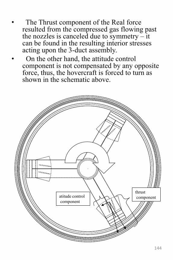
• The Thrust component of the Real force resulted from the compressed gas flowing past the nozzles is canceled due to symmetry – it can be found in the resulting interior stresses acting upon the 3-duct assembly.
• On the other hand, the attitude control component is not compensated by any opposite force, thus, the hovercraft is forced to turn as shown in the schematic above.
atitude control
component
thrust
component
144
The three main advantages of the
new design are:
• The attitude control is no longer dependent on the main thruster fan, meaning that the craft can perform a full turn even at zero speed (which is unprecedented in the history of hovercraft)
• The resultant of the attitude control components of all three control nozzles is perfectly balanced, thus the craft will have no residual sideway skids (such is the case with our first design)
• The center of application for the forces that control the attitude of the craft is inherently near the center of mass of the craft(because it‟s inside the skirt), yielding no dangerous leaning.
145
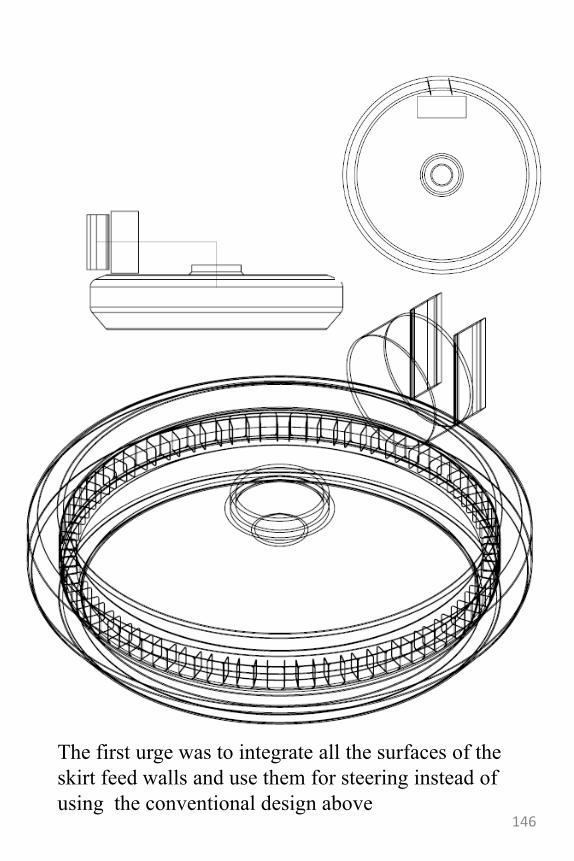
The first urge was to integrate all the surfaces of the
skirt feed walls and use them for steering instead of
using the conventional design above146
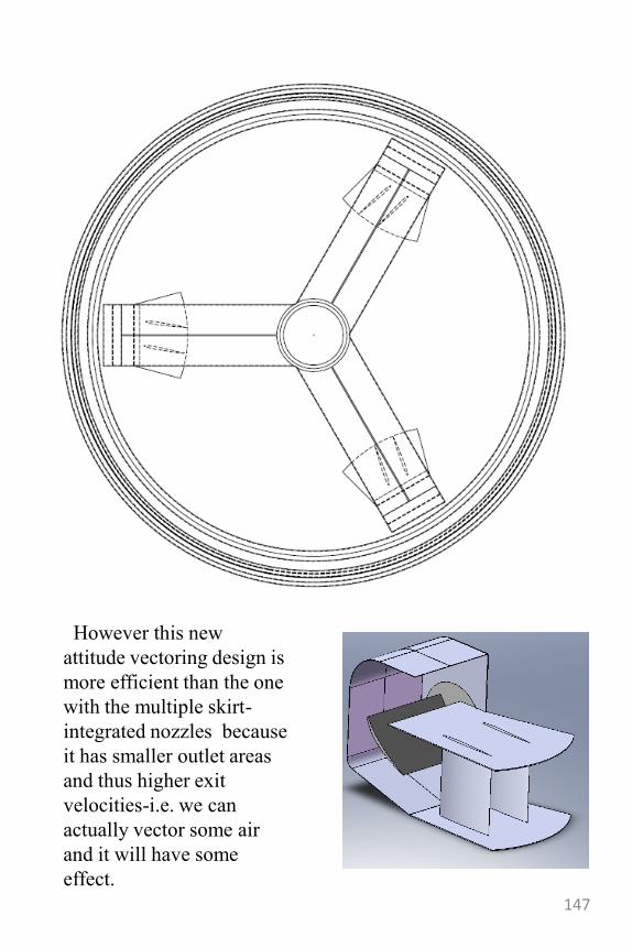
However this new
attitude vectoring design is
more efficient than the one
with the multiple skirt-
integrated nozzles because
it has smaller outlet areas
and thus higher exit
velocities-i.e. we can
actually vector some air
and it will have some
effect.
147
148
149
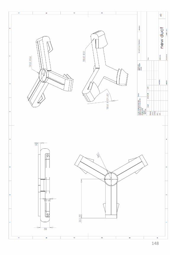
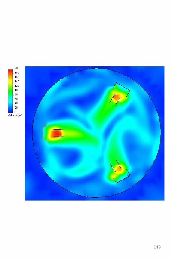
Fan noise reduction
devices-studies
• The following noise
reduction techniques are
also a result of the tip jet
study-more precisely they
are a result of trying to
integrate a centrifugal
compressor into a fan
blade.
150
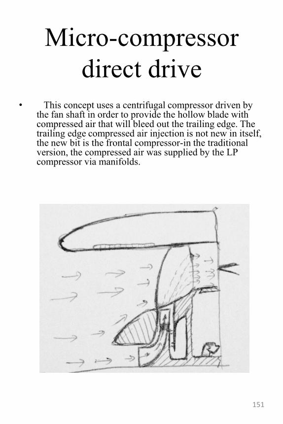
Micro-compressor
direct drive
• This concept uses a centrifugal compressor driven by the fan shaft in order to provide the hollow blade with compressed air that will bleed out the trailing edge. The trailing edge compressed air injection is not new in itself, the new bit is the frontal compressor-in the traditional version, the compressed air was supplied by the LP compressor via manifolds.
151
Micro-compressor
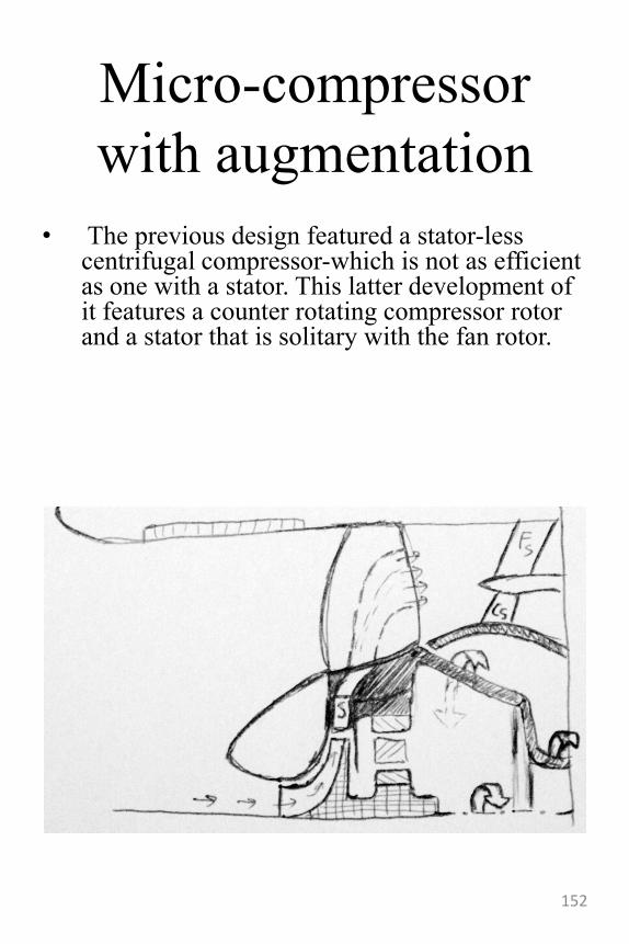
with augmentation
• The previous design featured a stator-less centrifugal compressor-which is not as efficient as one with a stator. This latter development of it features a counter rotating compressor rotor and a stator that is solitary with the fan rotor.
152
The toxi-jet
• A theoretically (and hopefully never materialized) idea of mine was to use the atmosphere‟s mixture of gases, nitrogen and oxygen to obtain a combustive mixture. This would only happen at high temperatures but the reaction is exothermal and hence could be used to sustain the burning. It goes without saying that the toxins that would result are really harmful and such a jet engine should never be allowed to fly even if it could be technologically available should it be small enough and powerful enough to put on an airplane that would fly virtually endlessly.
153
Constant volume
burning jet engine
designs• -stato-dinamo-reactor
• -valveless pulsejet unison
ring variation
• -semi-nozzled cam valve
system-aero engine
• -turbine obturator
154
Stato-dinamo-reactor
the rotating ramjet
• What started as a more theoretical far fetched study quickly developed into this more feasible concept of having a plurality of ramjet engines arrayed around a main drum and having their inlets shaped as a fan rotor stage. This way, after it is started using an APU or GPU, a S-D-R would be able to operate at zero ground speed (even if inefficiently).
• The applications for this engines are mainly military (as they are the only current >Mach 1 operators).
• The benefits of having such an engine are the result of it‟s capability to work (poorly) at zero ground speed and (optimal) al high Mach numbers.
• As one can imagine, the rpm of the engine is turned down as it reaches it‟s optimum air speed and the front intake lips are re-aligned with the rest of the ram-jet array.
155
The schematics of this
engine
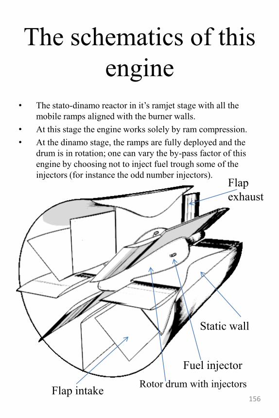
• The stato-dinamo reactor in it‟s ramjet stage with all the
mobile ramps aligned with the burner walls.
• At this stage the engine works solely by ram compression.
• At the dinamo stage, the ramps are fully deployed and the
drum is in rotation; one can vary the by-pass factor of this
engine by choosing not to inject fuel trough some of the
injectors (for instance the odd number injectors).
Flap intakeRotor drum with injectors
Fuel injector
Static wall
Flap
exhaust
156
The unison ring valve
constant volume
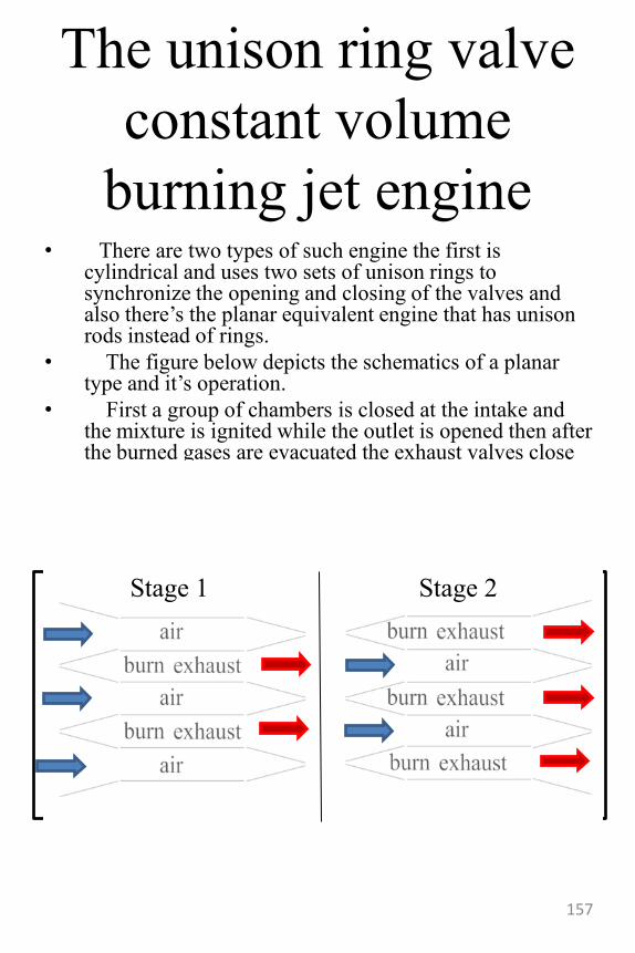
burning jet engine• There are two types of such engine the first is
cylindrical and uses two sets of unison rings to synchronize the opening and closing of the valves and also there‟s the planar equivalent engine that has unison rods instead of rings.
• The figure below depicts the schematics of a planar type and it‟s operation.
• First a group of chambers is closed at the intake and the mixture is ignited while the outlet is opened then after the burned gases are evacuated the exhaust valves close and the intake is opened. Control rods are used to flip the intake and outlet flap valves.
• The next invention will work great with this one if we were to adapt the exhaust valves to that design.
Stage 1 Stage 2
157
The semi-nozzle cam
actuated constant
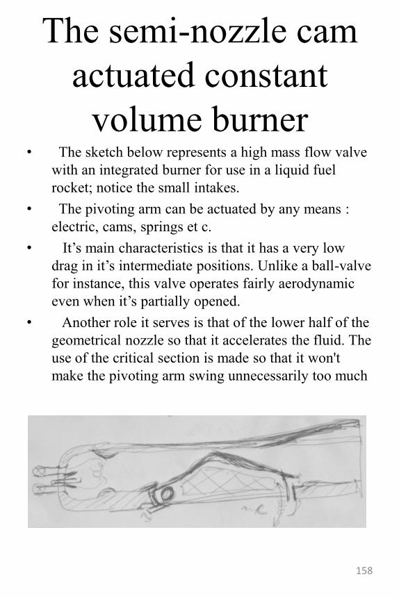
volume burner• The sketch below represents a high mass flow valve
with an integrated burner for use in a liquid fuel
rocket; notice the small intakes.
• The pivoting arm can be actuated by any means :
electric, cams, springs et c.
• It‟s main characteristics is that it has a very low
drag in it‟s intermediate positions. Unlike a ball-valve
for instance, this valve operates fairly aerodynamic
even when it‟s partially opened.
• Another role it serves is that of the lower half of the
geometrical nozzle so that it accelerates the fluid. The
use of the critical section is made so that it won't
make the pivoting arm swing unnecessarily too much
158
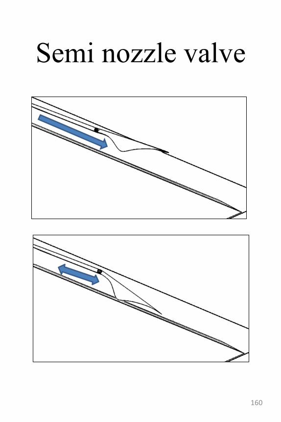
Other semi-nozzle
valve systems
• This layout features a superior semi nozzle valve mounted on an aerospikenozzle. Because of it‟s superior position it will perform less poorly in transitions because the flow will tend to be attached to the inferior part of the nozzle, i.e. the ramp of the aerospike via the Coanda effect.
• At the closed position the burner lets air and fuel mix and burn at a constant volume – providing a much better thermodynamic efficiency.
• At the open position the burned gases are let out the aerospike ramp and accelerated in the de Laval nozzle formed by the ramp and the interior of the semi-nozzle valve.
• The valve position can be controlled electrically or hydraulically depending on the application and the desired configuration.
159
Semi nozzle valve
160
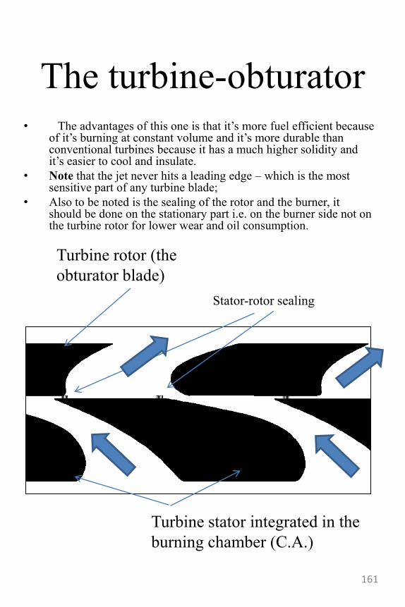
The turbine-obturator• The advantages of this one is that it‟s more fuel efficient because
of it‟s burning at constant volume and it‟s more durable than conventional turbines because it has a much higher solidity and it‟s easier to cool and insulate.
• Note that the jet never hits a leading edge – which is the most sensitive part of any turbine blade;
• Also to be noted is the sealing of the rotor and the burner, it should be done on the stationary part i.e. on the burner side not on the turbine rotor for lower wear and oil consumption.
Turbine rotor (the
obturator blade)
Turbine stator integrated in the
burning chamber (C.A.)
Stator-rotor sealing
161
Positron-electron
propulsion
• The main aspect of this propulsion system is that it doesn‟t require a work fluid (or mass).
• Another very important aspect is that if accelerated beyond a critical velocity, the particles we create are more efficient at giving us thrust than photons would be.
• Basically, the e+e- propulsor uses the pair formation effect encountered when a high energy photon enters the field of a heavy atom. The energy of the photon is converted into a pair of matter and anti-matter particles. In our case we shall discuss the electron-positron formation.
• After their formation we might capture those particles and guide them to a betatron where we could accelerate them at relativistic speeds and eject them out into space trough magnetic nozzles.
162
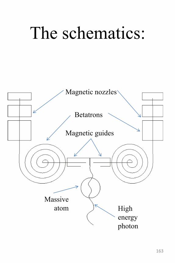
The schematics:
Magnetic nozzles
Betatrons
Magnetic guides
High
energy
photon
Massive
atom
163
Photonic vs. corpuscular
momentum
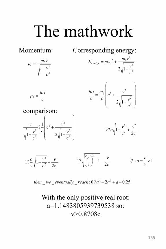
• Following on the positron-electron propulsion system I sat out to see how it would compare to a simpler photon-momentum engine (basically a laser)
• Comparing the two momentafor the same energy requirement bearing in mind the fact that we have to generate the electron and positron. Meaning that even if they were material – and thus better for propulsion, they still were “expensive” energy-wise.
164
The mathwork
2
2
0
1c
v
vmpe
2
2
2
02
0_
12c
v
vmcmE etotal
2
2
220
12c
v
vc
c
m
c
h
c
hp
2
2
22
2
2
12
1?
1c
v
vc
c
c
v
v
c
v
c
vcv
21?
2
2
2
c
v
c
v
v
c
21?1
2
2
c
v
v
c
21?1
2
25.02?0:___ 24 aaareacheventuallywethen
1: v
caif
With the only positive real root:
a=1.1483805939739538 so:
v>0.8708c
Momentum: Corresponding energy:
comparison:
165

Impossible
• As long as the impossible is imaginable, the unimaginable will be possible.
• Just because everyone sais one thing is impossible it doesn‟t mean it really is. It means that the prize for doing it is bigger and that the competition for it is little. It doesn‟t get much better than that!
166
Setting goals
• For instance you can start (ad absurdum) by trying to make an engine using a certain geometry. Why? Because you think you can do it. And therefore you should do it. Never underestimate the power of small victories.
• Another example is to try and make an engine with a minimum number of parts or with a lower diameter while maintaining the same power. Maybe you‟d like to have a minimum weight or a low maintenance cost -which would imply as little stress on the parts and a high modularity.
• There are virtually no limits to what you can set as a goal and once you‟ve done that you‟ll be surprised on how quickly ideas come flowing in.
167
Using principles• This may be a drawback at one point-as experience
starts to short circuit the thinking process and offeres
predetermined solutions without a thought. However,
it is quite useful to try and make an invention that
involves a certain principle. Such principles might be
from other fields – and in fact those are the most
interesting ones.
• For instance you may use the supercirculation effect
on the nozzle instead of a wing.
• One example that I‟m very found of is a device that
measured the thickness of an oil film by measuring
the electrical capacity (the piece looked like a
condenser).
• There are plans for aircraft flying on the Magnus
effect or compressors that use an acoustic stationary
waves. Some stealthy materials use what‟s called
“moth eyes” for reducing the reflection of an incident
radar wave.
• They may not look efficient but it is your job as an
inventor to make it efficient and then be it‟s advocate-
i.e. find a branch where only it would perform much
better than the rest. Once you‟ve identified the things
only your device can perform then people will start
thinking of buying it.
168
Using variations
• Earlier you‟ve seen variations on the ram air turbine engine and the cuboidal piston engines.
• The truth is that it really takes a lot to make something that is practical. For that you need variations on the theme to make a sort of natural selection-ideas that are more appealing will tend to stay and those which are not viable will become latent.
• One example of easy variations are linkages: instead of a crank-shaft you can use a scotch yoke or other, more bizarre linkages and see how they work.
169
Math
• Mathematics and especially geometry provides a lot of ingenious solutions and principles you can make use of.
• A good example is of prime numbers-they‟ve been in use everywhere from ciphers to jet engines. For instance the fan noise from a turbine engine is mainly produced by the rotor-stator interaction. There are techniques to optimize this but one of them is extremely simple and works quite well in conjunction with the others: make the number of blades of stator and rotor have only one common denominator or, even better, none. It is impossible to have the rotor blades in prime numbers because usually rotors work better with even numbers.
• Also take a look at the “ancient” mathematical devices used to calculate reregulate surfaces or slide rules. A lot of them can inspire great ideas.
• You can also amuse yourself with Reuleauxpolygons and other such mathematical “toys”
170
Engine building blocks• Turbines- I‟ve mentioned earlier that the first jet engine did not have a
turbine but a piston engine to drive it‟s compressor. Turbines are a great idea and extract a lot of energy from the given flow of air-thus they can provide the compressor with more work without having to carry a lot of weight. However turbines are notoriously difficult to engineer and work with, Frank Whittle‟s turbine engine wasn‟t great because it featured a turbine – people tried the concept before- but it was great because it had a Working turbine – which was where everyone else had failed till that day.
• Valves-there‟s a great variety of valves from high speed to high mass flow and to high aerodynamic efficiency. Also you‟ll need to take a look at the various ways they are actuated and figure out which one is better suited to your design.
– Valves can be used –and in fact are used-to create engines that burn at constant volume (although it‟s not the only solution-see the Wankel an the pulse engines)
• Intercooler-isothermal evolutions are the least demanding in terms of work needed to compress a fluid. This is why people have tried all sorts of things to cool down the compressed fluid trough a compressor. There is a subtle but important difference between pressure ratio and the compression ratio. Intercoolers come in all shapes and sizes, we can consider injecting water into the compressor as a process of cooling the stream of air for instance.
• Linkages- this should go in front of the pistons because it can really give life to entire new families of engines from the in-line V-12 and the boxer to the radial and axial engines (which are really rare but extremely interesting). Another interesting layout is that of the Delticengine. Don‟t forget about the cam engines either!
• Pistons-They too come in all shapes and sizes (it‟s needlless to say that bigger diameters are not necessarily better). Rotary pistons are a bit too exotic to generalize but the matter of the toroidal engine can be squeezed in this chapter – so you should definitely look it up. Another very nice piston is used by the flap-piston engine-just brilliant. I‟ve mentioned the Deltic engine with it‟s opposite pistons, well turn the Deltic inside out and you might get something resembling the Britalus. Kenneth Porter‟s Britalus engine is one of the most famous two piston engines that works on the Brayton cycle (the other one being George Brayton‟s). It‟s also interesting because the pistons are driven by cams instead of traditional linkages.
• The list is opened to anything you might want to add, and you should add things to it just for the fun of it, it‟s always that wacky device nobody cared about that makes a revolutionary design work – and I‟m not saying this just because I‟m thrilled by the flap engine and the Britalus.
171
Cycles and engines
• Try to keep in mind that
there isn‟t a necessary link
between the cycle of an
engine and the fact that it‟s a
piston or a turbine engine.
• There are piston engines that
use the Brayton cycle and
there are jet engines that can
work on constant volume
burner cycles-not
necessarily the pulsejets.
172

Ending:
Mistakes are inevitable and should be
embraced.
A good inventor studies his mistakes but
does not run nor hide from them.
A lot of people, after some success, try
only easy tasks for fear of loosing their
“name” if they were to make a wrong choice
in a harder project. Personally I‟m trying to
avoid becoming one of them
We‟re human, we make mistakes, that‟s
what we do-it‟s what we‟re good at!
173
References
• [1] Rotary piston machines – Felix Wankel London Iliffe books ltd. 1963
• [2] The jet engine- Rolls Royce fifth edition -1996
• [3] Aeroacoustic Prediction Codes-NASA 2000- P. Gliebe GE Aircraft Engines, Cincinnati, Ohio, R. Mani GE-Corporate Research Development, Schenectady, New York, H. Shin GE Aircraft Engines, Cincinnati, Ohio, B. Mitchell, G. Ashford, S. Salamah, and S. Connell GE-Corporate Research Development, Schenectady, New York
• [4]Pratt and Whitney PW100 maintenance manual
• [5] YF-23 Utility manual Northrop Grumman corp. 1990
• [6] CFM 56 5-a training manual- Engine systems
• [7] CFM 56 5-a training manual- Basic engine
• [8] CFM 56 5-a training manual- Component identification answer book
• [9] Aircraft Engine Design Second Edition Jack D. Mattingly University of Washington William H. Heiser U.S. Air Force Academy David T. Pratt University of Washington
• [10] Aero Analysis And Design Of Flight Vehicles Structures_-_Bruhn
174
References
• [11] How Round Is Your Circle?: Where Engineering and Mathematics Meet- John Bryant, Chris Sangwin Princeton University Press 2008
• [12] freepatentsonline.com
• [13] Flight global archive
• [14] Derwent Mk.9 Aero engines maintenance manual – Rolls Royce
• [15] GasTurb 11 Design and Off-Design Performance of Gas Turbines by Joachim Kurzke 2007
• [16] RX-7 Factory service material Mazda 1988
• [17]Rotary Engine by Kenichi Yamamoto, Toyo kogyo co.ltd
• [18] 17]Rotary Engine by Kenichi Yamamoto, Mazda
• [19] Gas Turbine Performance Second Edition Paul Fletcher Philip P. Walsh Rolls Royce
• [20] First Stage of the Centrifugal Compressor Design with Tandem Rotor Blades Daniel Hanus, Tomáš Čenský Jaromír Nevečeřal, Vojtěch Horký
175
References
• [21]Flying lightness – promises for structural elegance Adriaan Beukersand Ed van Hinte 010 publishers 2005
• [22] First read this – system engineering in practice Ed van Hinte and Michael van Tooren 010 publishers 2008
• [23] Introducere în propulsia neconventionalã-Virgil Stanciu, Adriana Miclescu Editura Bren 2003
• [24] Aviatia moderna-realizari si perspective- Gheorghe Zarioiu EdituraScrisul Romanesc 1980
• [25] CFM 56 5-a training manual- fault detection and annunciation
• [26] CFM 56 5-a training manual- nacelle
• [27] Transmisii neconvenţitonale-Petre-Lucian Seiciu, Tiberiu LaurianEditura Printech 2007
• [28] Wave-Rotor-Enhanced Gas Turbine Engine Demonstrator Gerard E. Welch U.S. Army Research Laboratory, Glenn Research Center, Cleveland, Ohio Daniel E. Paxson Glenn Research Center, Cleveland, Ohio Jack Wilson Dynacs Engineering Company, Inc., Brook Park, Ohio Philip H. Snyder Rolls-Royce Allison, Indianapolis, Indiana
• [29] Gas Turbine Handbook: Principles and Practices 3rd Edition Tony Giampaolo, MSME, PE The Fairmont Press 2006
• [30] Wind-Tunnel Development of an SR-71 Aerospike Rocket Flight Test Configuration Timothy R. Moes, Brent R. Cobleigh, Timothy R. Conners,
• Timothy H. Cox, Stephen C. Smith, and Norm Shirakata
176

177

178


![Cognitive biases: A visual study guide [Eric Fernandez]](https://img.pdfslide.tips/doc/110x75/577d36331a28ab3a6b927394/cognitive-biases-a-visual-study-guide-eric-fernandez.jpg)