Embed Size (px)
Citation preview

Agilent 700 Series ICP-OESMaintenance Tips & Tricks
Maintenance Checklist (1)
Daily
• Inspect nebulizer / torch
• Inspect pump tubing
• Empty drain vessel
Weekly
• Clean torch
• Inspect cone (axial) or snout (radial)
• Inspect bonnet (radial)

Maintenance Checklist (2)
Monthly
• Clean spraychamber
• Clean nebulizer
• Inspect the state of induction coil
• Verify that the water level in water recirculator is sufficient
– If low, add more water
– Do not add more Chloramine - T without flushing out the recirculator
• Clean/check air filter on top of ICP-OES (behind chimney)

Nebulizer Cleaning
Concentric Glass – High sensitivity nebulizer: • Soak in Aqua Regia• Back flush with water or vacuum
NEVER sonicate • Inner capillary may shatter or crack
– This is NOT always visually apparent

Wavelength Calibration using S21Agilent ICP-OES can be calibrated using S21 Oil standard
• Perform dark current scan/wavelength calibration monthly
ICP Expert software:
1. Go to ‘Supplied Worksheets’ directory2. Rename worksheet ‘wavelength calibration.vws’ to ‘wavelength
calibration aqueous.vws’3. Rename worksheet ‘S21 organic matrix wavelength
calibration.vws to ‘wavelength calibration.vws’
ICP Expert II software:
1. From within the Wavelength Calibration page, select Browse and locate the S21 method within the Supplied Worksheets
Weekly Torch Maintenance
Inspect Torch for Cracks or Deformations • Replace damaged torches
Inspect injector tube for sample buildup
Inspect outer tube for deposits
Weekly Inspection
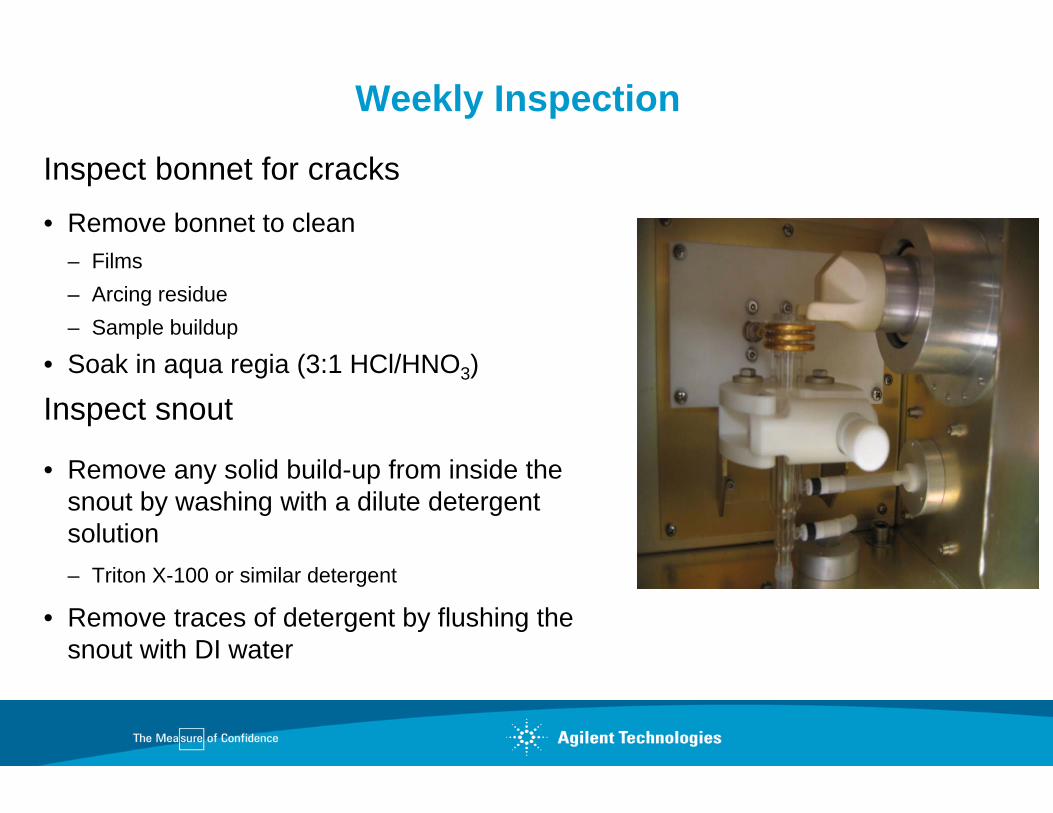
Inspect bonnet for cracks• Remove bonnet to clean
– Films– Arcing residue– Sample buildup
• Soak in aqua regia (3:1 HCl/HNO3)
Inspect snout
• Remove any solid build-up from inside the snout by washing with a dilute detergent solution – Triton X-100 or similar detergent
• Remove traces of detergent by flushing the snout with DI water

Cleaning Torch
Rinse the torch with clean water to remove salt deposits, and allow to dry before use
To remove other deposits or stains• Soak in aqua regia (3:1 HCl/HNO3) overnight• Rinse well with water and allow to dry before use• Use a pipe cleaner dipped in aqua regia to remove persistent
compounds from the injector tube
2% HF can be used to remove stubborn stains
• Will weaken the torch over time

Periodic Torch Maintenance (2)
Devitrification Cleaning (radial ICP only)• Soak in 2% HF Acid• Monitor every 5 minutes• Rinse and Dry
Torch for axial ICP will exhibit devitrification after first use• DO NOT spend time cleaning• Monitor for cracks

Torch Alignment (1)
Must be Concentric within Coil
• Uneven RF can cause Torch Meltdown
• Arcing between Plasma & Coil

Replacing Radial Torch
Position the top of the torch intermediate tube at least 2 mm below the induction coil• Arcing may occur if too low• Torch Meltdown or Plasma
Ignition Failure if too high
3 mm

Replacing Axial Torch
Align the torch horizontally by positioning it so that the intermediate tube of the torch is approximately 3 mm to the left of the left end of the induction coil
3-5 mm

+ 3 mm0 mm
- 3 mmTop View of Torch
Horizontal Torch Alignment (4)
Perform after Radial or Axial torch removal/replacement• +/- 1.5 mm from center• Go to Torch Alignment page in Instrument Module• Select TORCH method provided with the software• Use the provided tuning solution (1:10)• Method scans for Mn at 257.610 nm

Vertical Torch Alignment
Perform after AXIAL torch removal/ replacement• Go to Torch Alignment page in Instrument Module• Select TORCH method provided with the software• Use the provided tuning solution (1:10)• Select VERTICAL box in software• Method scans for Mn at 257.610 nm

Spraychamber Cleaning Glass Cyclonic
Cleaning required when the sample aerosol begins to BEAD UP on the spraychamber walls• Remove spraychamber from instrument• Soak in aqua regia, rinse and replace• NOTE: Sonication may damage glass spraychamber
– Place in a small beaker BEFORE starting the sonicator

Water Cooling System
Set thermostat at 21- 25oC
Check correct water level• Fill with DI water only – not > 18 m ohms
Prevent growth of aerobic bacteria by adding Chloramine -T (Trihydrate)
• Only when water is changed• Add 1 gram for each liter of water used (0.1%)• Read owner’s service manual

Troubleshooting (1)
90% of all ICP-OES related problems are in the sample introduction area
There are common procedures available to indicate if there is a sample introduction problem
Troubleshooting (2)
Diagnose Sample Introduction Problems Using Yttrium• Red bullet should not pulsate
– Radial - Bullet should be ~ 1mm above top of torch – Axial - Bullet should be between second and third coils
The blue portion of the plasma represents the NORMAL analytical zone and should be clearly visible• Radial normal analytical zone should be 3 mm to 16 mm above the coil• Axial normal analytical zone should extend to the cooled cone • The orange plasma tail should be fanned around the cone orifice

Plasma Ionization Zones
Preheating Zone
Viewing height above load coil in mm’s
Induction Zone
Initial Radiation Zone
Normal Analytical Zone
Plasma Tail25201510
50

Radial Plasma
Slit Height
Work coil
Viewing VolumeFireball
Central Channel
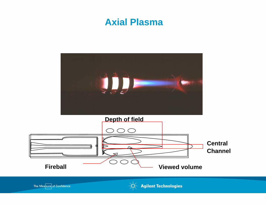
Axial Plasma
Depth of field
Central Channel
Viewed volumeFireball

Troubleshooting (3)
Low analytical signal• Standards prepared incorrectly• Blocked nebulizer or low nebulizer gas flow• Blocked injector• Bad pump tubing• Conditions not optimized

Troubleshooting (4)
It’s a good idea to keep a log of the intensities whenever you run the Torch Alignment program

Troubleshooting (5)
Poor precision• Determine if it is drift or noise related• Check the nebulizer for blockage• Check the torch and injector tube• Check the pump and pump tubing
Summary
Frequently, degradation of results is due to problems associated with the sample introduction area rather than the instrument itself
• Check plasma with Y solution
• Maintain the system
• Check wavelength calibration
• Monitor intensity of calibrations within a worksheet