Embed Size (px)
Citation preview
1. INDICADOR DE LUGAR-NOMBRE DEL AERÓDROMO LEPA/LESJ - PALMA DE MALLORCAAERODROME LOCATION INDICATOR - NAME
AIP AD 2-LEPA/LESJ 1ESPAÑA WEF 24-MAY-18
2. DATOS GEOGRÁFICOS Y DE ADMINISTRACIÓN DEL AERÓDROMO
ARP: 393306N 0024420E. Ver AD 2-LEPA/LESJ ADC.Distancia y dirección desde la ciudad: 8 km E.Elevación: 8 m/27 ft.Ondulación geoide: 48.98 m ± 0.10 m (1).Temperatura de referencia: 31°C.Declinación magnética: 1°E (2015).Cambio anual: 6.2’E.Administración AD: CIV: Aena.
MIL: Ejército del Aire.Dirección: CIV: Aeropuerto de Palma de Mallorca, 07611 Palma.
MIL: Base Aérea de Son San Juan. Crta de Manacor s/n07071 Palma
TEL: CIV: +34-971 789 000 FAX: CIV:+34-971 789 010/1/2MIL: +34-971 497 504 MIL:+34-971 497 605
AFTN: CIV: LEPA E-mail: CIV: [email protected]: LESJ MIL: [email protected]
Tránsito autorizado: IFR/VFR (2).Observaciones: (1) Para todos los puntos del AD.
(2) No se admite tráfico VFR excepto vuelos hospitales,militares, búsqueda y salvamento y de estado del 1 MAY al31 OCT, de viernes a domingo, HR: H24.
3. HORARIO DE OPERACIÓN
Aeropuerto: H24. (1)Aduanas e Inmigración: H24.Servicios médicos y de sanidad: Ver GEN 1.4.AIS/ARO/OPV: H24.Información MET: H24.ATS: H24.Abastecimiento de combustible: H24.Asistencia en tierra: H24.Seguridad: H24.Deshielo: H24.Observaciones: (1) Aeronaves de estado extranjeras, ver casil la 20:
Reglamentación local.
4. SERVICIOS E INSTALACIONES PARA CARGA Y MANTENIMIENTO
Instalaciones para el manejo de carga: CIV: Sin limitaciones.MIL: 1 horquilla elevadora (uña) hasta 8.000 Kg;
2 horquillas elevadoras (uñas) hasta 4.500 Kg.Tipos de combustible: CIV: JET A-1.
MIL: F-34.Tipo de lubricante: MIL: G-354, G-395, H-573, H-542, O-156, O-1236, S-750,
S-753.Capacidad de reabastecimiento: CIV: Sin limitaciones.
MIL: Cisternas: 40000 L; 22.5 L/s.Cisternas: 20000 L; 16.66 L/s.
Instalaciones para el deshielo: Servicio prestado por el agente handling.Superficie de deshielo para aeronaves enPRKG 104, 106, 108 y 114 a 118B.
Espacio disponible en hangar: No.Instalaciones para reparaciones: CIV: Reparaciones de poca importancia por
las compañías.Observaciones: MIL: GPU: Unidad de CA (hasta 100 KVA) y CC (hasta 2500 A).
Agentes de rampa:ACCIONATEL: +34-971 789 441FAX: +34-971 789 910Móvil: +34-607 536 745E-mail: [email protected]: PMIIHXH
GROUNDFORCETEL: +34-971 789 505 / +34-971 178 267.FAX: +34-971 789 603Móvil: +34-610 196 151E-mail: [email protected]: PMIGFXH
AERODROME GEOGRAPHICAL AND ADMINISTRATIVE DATA
ARP: 393306N 0024420E. See AD 2-LEPA/LESJ ADC.Distance and direction from the city: 8 km E.Elevation: 8 m/27 ft.Geoid undulation: 48.98 m ± 0.10 m (1).Reference temperature: 31°C.Magnetic variation: 1°E (2015).Annual change: 6.2’E.AD administration: CIV: Aena.
MIL: Ejército del Aire.Address: CIV: Aeropuerto de Palma de Mallorca, 07611 Palma.
MIL: Base Aérea de Son San Juan. Crta de Manacor s/n07071 Palma
TEL: CIV: +34-971 789 000 FAX: CIV:+34-971 789 010/1/2MIL: +34-971 497 504 MIL:+34-971 497 605
AFTN: CIV: LEPA E-mail: CIV: [email protected]: LESJ MIL: [email protected]
Approved traffic: IFR/VFR (2).Remarks: (1) For all AD points.
(2) VFR traffic is not accepted except for hospital, military, searchand rescue and State flights from MAY 1st to OCT 31st fromFriday to Sunday, HR: H24.
OPERATIONAL HOURS
Airport: H24. (1)Customs and Immigration: H24.Health and Sanitation: See GEN 1.4.AIS/ARO/OPV: H24.MET briefing: H24.ATS: H24.Fuelling: H24.Handling: H24.Security: H24.De-icing: H24.Remarks: (1) Foreign State aircraft, see item 20: Local regulations.
HANDLING SERVICES AND FACILITIES
Cargo facilities: CIV: No limitations.MIL: 1 forklift (claw) up to 8,000 Kg;
2 forklifts (claws) up to 4,500 Kg.Fuel types: CIV: JET A-1.
MIL: F-34.Oil types: MIL: G-354, G-395, H-573, H-542, O-156, O-1236, S-750, S-753.
Refuelling capacity: CIV: No limitations.MIL: Trucks: 40000 L; 22.5 L/s.
Trucks: 20000 L; 16.66 L/s.De-Icing facilities: Service provided by handling operator.
Aircraft de-icing area on PRKG 104, 106, 108 and 114 to118B.
Hangar space: No.Repair facilities: CIV: Minor repairs by operating companies.
Remarks: MIL: GPU: AC (up to 100 KVA) and DC (up to 2500 A) units.
Ramp agents:ACCIONATEL: +34-971 789 441FAX: +34-971 789 910Mobile phone: +34-607 536 745E-mail: [email protected]: PMIIHXH
GROUNDFORCETEL: +34-971 789 505 / +34-971 178 267FAX: +34-971 789 603Mobile phone: +34-610 196 151E-mail: [email protected]: PMIGFXH
AIS-ESPAÑA AIRAC AMDT 04/18
AD 2-LEPA/LESJ 2 AIPWEF 29-MAR-18 ESPAÑA
AIRAC AMDT 02/18 AIS-ESPAÑA
IBERIATEL: +34-971 628 802FAX: +34-971 789 258Móvil: +34-660 327 184E-mail: [email protected]: PMIKIIB, PMIKQIB
Agentes de rampa de Aviación General y Negocios:GENERAL AVIATION SERVICE GASTEL: +34-913 936 906FAX: +34-913 936 671Móvil: +34-685 938 716E-mail: [email protected]: PMIGAXH
GESTAIRTEL: +34-916 782 648FAX: +34-971 789 674Móvil: +34-609 001 137E-mail: [email protected]: MADOOG5
JETLAND EXECUTIVE SERVICESMóvil: +34-669 922 395E-mail: [email protected]
MALLORCAIRTEL: +34-971 789 522FAX: +34-971 787 932Móvil: +34-609 734 727E-mail: [email protected]: PMIZJXH
MELENDEZTEL: +34-971 268 276FAX: +34-971 789 897Móvil: +34-659 949 916E-mail: [email protected]: PMIGMXH
SKY VALET SPAINTEL:+34-916 782 648FAX: +34-971 789 674Móvil: +34-609 001 137E-mail: [email protected]: MADOOG5
SWISSPORTTEL: +34-971 789 200FAX: +34-971 789 201Móvil: +34-620 940 547E-mail: [email protected]: PMIAPXH
5. INSTALACIONES PARA LOS PASAJEROS
Hoteles: MIL: Sí.Restaurante: Si.Transporte: CIV: Autobuses y taxis.
MIL: Vehículo según disponibilidad, previa petición (PPR).Instalaciones médicas: CIV: Servicio de ambulancias.
MIL: Primeros auxilios y ambulancia. (1)Banco/Oficina Postal: Sí.Información turística: Sí.Observaciones: (1) HR 0730-1430 LT.
6. SERVICIOS DE SALVAMENTO Y EXTINCIÓN DE INCENDIOS
Categoría de incendios: CIV: 9. (1)MIL: 4. (2)
Equipo de salvamento: MIL y CIV: De acuerdo a la categoría de incendiospublicada.
Retirada de aeronaves inutilizadas:CIV: cojines de varias capacidades, eslingas de varias capacidades, 4 vigas
transversales de diferentes capacidades (MAX. 25 TM), esteras ymaterial accesorio para su uso, camión con grúa de capacidad máxima2.4 TM, 2 plataformas recuperadoras 30 TM de carga (CAT III) y materialauxiliar. Medios externos: grúas de 40 a 200 TM y camiones grúa de 30a 220 TM. (3)
MIL: Tractor remolcador y grúa de rescate de aeronaves hasta 30 TM.Observaciones: (1) Objetivo operacional de tiempo de respuesta hasta el
punto más alejado de las pistas menor de 3 MIN.(2) Se proporcionará nivel 6, previa solicitud PPR con 48 horas
de antelación.(3) Teléfono de contacto para retirada de aeronaves
inutilizadas: Ejecutivo Servicio: +34-971 789 595.
IBERIATEL: +34-971 628 802FAX: +34-971 789 258Mobile phone: +34-660 327 184E-mail: [email protected]: PMIKIIB, PMIKQIB
Ramp agents for General and Business Aviation:GENERAL AVIATION SERVICE GASTEL: +34-913 936 906FAX: +34-913 936 671Mobile phone: +34-685 938 716E-mail: [email protected]: PMIGAXH
GESTAIRTEL: +34-916 782 648FAX: +34-971 789 674Mobile phone: +34-609 001 137E-mail: [email protected]: MADOOG5
JETLAND EXECUTIVE SERVICESMobile phone: +34-669 922 395E-mail: [email protected]
MALLORCAIRTEL: +34-971 789 522FAX: +34-971 787 932Mobile phone: +34-609 734 727E-mail: [email protected]: PMIZJXH
MELENDEZTEL: +34-971 268 276FAX: +34-971 789 897Mobile phone: +34-659 949 916E-mail: [email protected]: PMIGMXH
SKY VALET SPAINTEL:+34-916 782 648FAX: +34-971 789 674Mobile phone: +34-609 001 137E-mail: [email protected]: MADOOG5
SWISSPORTTEL: +34-971 789 200FAX: +34-971 789 201Mobile phone: +34-620 940 547E-mail: [email protected]: PMIAPXH
PASSENGER FACILITIES
Hotels: MIL: Yes.Restaurant: Yes.Transportation: CIV: Buses and taxis.
MIL: Vehicle subject to availability, on request (PPR).Medical facilities: CIV: Ambulance service.
MIL: First aid and ambulance. (1)Bank/Post Office: Yes.Tourist information: Yes.Remarks: (1) HR 0730-1430 LT.
RESCUE AND FIRE FIGHTING SERVICES
Fire category: CIV: 9. (1)MIL: 4. (2)
Rescue equipment: MIL and CIV: In accordance with the fire categorypublished.
Removal of disabled aircraft:CIV: bags of various capacities, slings of various capacities, 4 transverse
beams of different capacities (MAX. 25 TM),mats and accessorymaterials for their use, truck crane of maximum capacity 2.4 TM, 230 TM load recovery platforms (CAT III) and auxiliary material.External facilities: cranes of 40 to 200 TM and truck cranes from 30to 220 TM. (3)
MIL: Towing tractor and aircraft rescue crane up to 30 TM.Remarks: (1) Operational objective of response time up to the furthest away
point of the runways less than 3 MIN.(2) Level 6 will be provided upon request PPR 48 hours in advance.
(3) Contact phone number for removal of disabled aircraft: ServiceExecutive: +34-971 789 595.
AIP AD 2-LEPA/LESJ 3ESPAÑA WEF 21-JUN-18
AIS-ESPAÑA AIRAC AMDT 05/18
7. DISPONIBILIDAD ESTACIONAL/REMOCIÓN DE OBSTÁCULOS
Equipo: Deshielo/antihielo de RWY 06L/24R y 06R/24L con urea, barredoracon cuchilla quitanieves, camión y tractores.
Prioridad: RWY, TWY, plataforma, vías de servicio y accesos.Observaciones: Periodo de aplicación del plan de nieve: desde el 01-NOV al
15-APR. (Ver tambien AD 1.2).
8. DETALLES DEL ÁREA DE MOVIMIENTO
Plataforma: Superficie: Hormigón y asfalto.Resistencia:
TWY LA: PCN 95/R/A/W/T;LB, LC, LQ, LY, Y2, Y3: PCN 54/R/A/W/T;LD, LF: PCN 101/F/A/W/T;LE: PCN 150/F/A/W/T;LG, LJ a LK, V, V1 a V2: PCN 87/F/B/W/T;LM: PCN 146/F/A/W/T;LP: PCN 122/R/A/W/T;T1 a T2: PCN 96/R/A/W/T;W5: PCN 46/R/B/W/T;Y1: PCN 44/F/C/W/T.
PRKG: 01 a 06, 24 a 26, 100 a 103B, 115 a 119: PCN 84/R/A/W/T;08 a 23B, 104 a 109, 114, 114B: PCN 46/R/B/W/T;27 a 29, 46 a 48, 50 a 52, 54 a 58, 120, 121, 123: PCN 90/R/B/W/T;30 a 44: PCN 81/R/A/W/T;60 a 68, 72, 80 a 86: PCN 96/R/A/W/T;88 a 98: PCN 122/R/A/W/T;150 a 159, 200 a 247, 311 a 318: PCN 54/R/A/W/T;301 a 310: PCN 95/R/A/W/T.
Plataforma MIL Este: PCN 85/R/A/W/T.Plataforma MIL Oeste: PCN 71/R/A/W/T.
Calles de rodaje: Anchura: 23 m, EXC S2: 25 m, N1 a N6: 29 m, N7 (exclusiva para helicópteros): 8.6 m,U (acceso a Plataforma MIL Este): 24 m, MU: 18 m.
Superficie: Asfalto y hormigón.Resistencia: H1: PCN 58/F/A/W/T;
H2: PCN 65/F/A/W/TH4 a H5: PCN 89/F/A/W/T; H6 a H8: PCN 62/F/A/W/T;H9 a H10: PCN 43/F/A/W/T;LINK: PCN 115/F/A/W/T EXC tramo entre J y SOUTH: PCN 83/F/C/W/T; MU: PCN 114/F/A/W/U;N1: PCN 72/F/A/W/T; N2 a N5: PCN 61/F/A/W/T;N6: PCN 91/F/A/W/T;N7: PCN 26/F/A/W/T;NORTH: PCN 49/F/B/W/T;S1, S3: PCN 96/F/A/W/T;S2: PCN 85/F/A/W/T;SOUTH: PCN 96/F/A/W/T EXC tramo entre S1 y H10: PCN 43/F/A/W/T.U: PCN 44/R/A/W/T.
Posiciones de comprobación: Altímetro: Plataforma: 4 m/14 ft EXC PRKG 58, 60y 62: 7 m/24 ft.
VOR: No.INS: Ver AD 2-LEPA/LESJ PDC.
Observaciones: Ninguna.
9. SISTEMAS Y SEÑALES DE GUÍA DE RODAJE
Sistema de guía de rodaje: Puntos de espera de la pista, puntos de esperaintermedios, barras de parada, luces de punto deespera intermedio, indicadores de posicióniluminados, letreros de NO ENTRY, indicador dedispositivo de frenado, luces de protección de pistae información LGTD y puestos de estacionamiento.
Señalización de RWY: Designadores, umbral, umbral desplazado (RWY 24R yRWY 06R), eje, faja lateral, punto de visada, zona de tomade contacto con clave de distancia y señales indicadorasde salida rápida de RWY 24L en TWY S1 y S2.
Señalización de TWY: Eje y faja lateral, EXC N7: eje.Observaciones: Ninguna.
SEASONAL AVAILABILITY/OBSTACLE CLEARING
Equipment: RWY 06L/24R and 06R/24L de-iced/anti-iced with urea, sweeperwith snow- plough blade, truck and tractors.
Priority: RWY, TWY, apron, service roads and entries.Remarks: Period of application of snow plan: from 01-NOV to 15-APR.
(See also AD 1.2).
MOVEMENT AREA DETAILS
Apron: Surface: Concrete and asphalt.Strength:
TWY LA: PCN 95/R/A/W/T;LB, LC, LQ, LY, Y2, Y3: PCN 54/R/A/W/T;LD, LF: PCN 101/F/A/W/T;LE: PCN 150/F/A/W/T;LG, LJ to LK, V, V1 to V2: PCN 87/F/B/W/T;LM: PCN 146/F/A/W/T;LP: PCN 122/R/A/W/T;T1 to T2: PCN 96/R/A/W/T;W5: PCN 46/R/B/W/T;Y1: PCN 44/F/C/W/T.
PRKG: 01 to 06, 24 to 26, 100 to 103B, 115 to 119: PCN 84/R/A/W/T;08 to 23B, 104 to 109, 114, 114B: PCN 46/R/B/W/T;27 to 29, 46 to 48, 50 to 52, 54 to 58, 120, 121, 123: PCN 90/R/B/W/T;30 to 44: PCN 81/R/A/W/T;60 to 68, 72, 80 to 86: PCN 96/R/A/W/T;88 to 98: PCN 122/R/A/W/T;150 to 159, 200 to 247, 311 to 318: PCN 54/R/A/W/T;301 to 310: PCN 95/R/A/W/T.
East MIL apron: PCN 85/R/A/W/T.West MIL apron: PCN 71/R/A/W/T.
Taxiways: Width: 23 m, EXC S2: 25 m, N1 to N6: 29 m, N7 (exclusively for helicopters): 8.6 m,U (access to East MIL apron): 24 m, MU: 18 m.
Surface: Asphalt and concrete.Strength: H1: PCN 58/F/A/W/T;
H2: PCN 65/F/A/W/TH4 to H5: PCN 89/F/A/W/T; H6 to H8: PCN 62/F/A/W/T;H9 to H10: PCN 43/F/A/W/T;LINK: PCN 115/F/A/W/T EXC section between J and SOUTH: PCN 83/F/C/W/T; MU: PCN 114/F/A/W/U;N1: PCN 72/F/A/W/T; N2 to N5: PCN 61/F/A/W/T;N6: PCN 91/F/A/W/T;N7: PCN 26/F/A/W/T;NORTH: PCN 49/F/B/W/T;S1, S3: PCN 96/F/A/W/T;S2: PCN 85/F/A/W/T;SOUTH: PCN 96/F/A/W/T EXC section between S1 and H10: PCN 43/F/A/W/T.U: PCN 44/R/A/W/T.
Check locations: Altimeter: Apron: 4 m/14 ft. EXC PRKG 58, 60 and 62: 7m/24 ft.
VOR: No.INS: See AD 2-LEPA/LESJ PDC.
Remarks: None.
TAXIING GUIDANCE SYSTEM AND MARKINGS
Taxiing guidance system: Runway-holding positions, intermediate holdingposition, stopbars, intermediate holding positionlights, l ighted position indicators, NO ENTRYboards, arresting gear marking, runway guard lights,LGTD information and stands.
RWY markings: Designators, threshold, threshold displaced (RWY 24R andRWY 06R), centre line, side stripe, aiming point, touchdownzone with distance code and rapid exit indicator markingsfrom RWY 24L in TWY S1 and S2.
TWY markings: Centre line and side stripe, EXC N7: centre line.Remarks: None.
AD 2-LEPA/LESJ 4 AIPWEF 01-MAR-18 ESPAÑA
AIRAC AMDT 01/18 AIS-ESPAÑA
10. OBSTÁCULOS DE AERÓDROMO
Obstáculos que perforan las Superficies de Cónica, Horizontal interna,Aproximación, Aproximación interna, Transición, Transición interna, Aterrizajeinterrumpido y Ascenso en el despegue establecidas en el Anexo 14; y lasáreas 2A y 3 establecidas en el anexo 15 de OACI:
Ver carpeta del DVD "Item 10".
Observaciones: Ver AD 2-LEPA/LESJ AOC.
11. SERVICIO METEOROLÓGICO PRESTADO
Oficina MET: Palma de Mallorca MET.HR: H24.METAR: Semihorario.TAF: 24 HR.TREND: Sí.Información: En persona y telefónica.Documentación de vuelo/Idioma: Cartas y lenguaje claro / Español.Cartas: Mapas previstos significativos y de viento y temperatura en altitud.Equipo suplementario: Presentador de imágenes de nubes, rayos y de
información radar.Dependencia ATS atendida: TWR, APP.Información adicional: Oficina principal: Valencia; H24; TEL: +34-963 690 750.
Oficina meteorológica Palma; H24; TEL: +34-971 789 319.
Observaciones: Existe resumen climatológico de aeródromo. Se hacen avisosde aeródromo.Existe, en las proximidades del aeródromo, una estaciónmeteorológica en 3936N 00242E. Ver ENR 5.3.
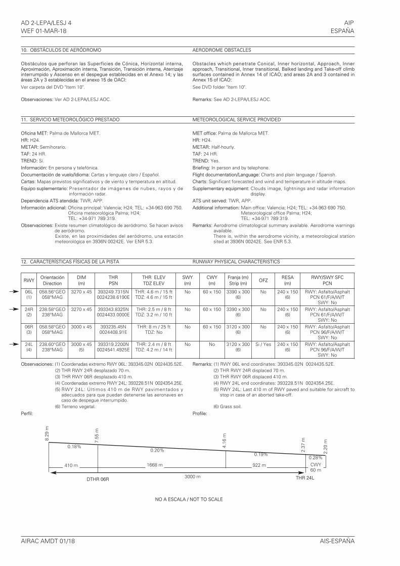
12. CARACTERÍSTICAS FÍSICAS DE LA PISTA
Observaciones: (1) Coordenadas extremo RWY 06L: 393345.02N 0024435.52E.(2) THR RWY 24R desplazado 70 m.(3) THR RWY 06R desplazado 410 m.(4) Coordenadas extremo RWY 24L: 393228.51N 0024354.25E.(5) RWY 24L: Últimos 410 m de RWY pavimentados y
adecuados para que puedan detenerse las aeronaves encaso de despegue interrumpido.
(6) Terreno vegetal.Perfil:
AERODROME OBSTACLES
Obstacles which penetrate Conical, Inner horizontal, Approach, Innerapproach, Transitional, Inner transitional, Balked landing and Take-off climbsurfaces contained in Annex 14 of ICAO; and areas 2A and 3 contained inAnnex 15 of ICAO:
See DVD folder "Item 10".
Remarks: See AD 2-LEPA/LESJ AOC.
METEOROLOGICAL SERVICE PROVIDED
MET office: Palma de Mallorca MET.HR: H24.METAR: Half-hourly.TAF: 24 HR.TREND: Yes.Briefing: In person and by telephone.Flight documentation/Language: Charts and plain language / Spanish.Charts: Significant forecasted and wind and temperature in altitude maps.Supplementary equipment: Clouds image, lightnings and radar information
display.ATS unit served: TWR, APP.Additional information: Main office: Valencia; H24; TEL: +34-963 690 750.
Meteorological office Palma; H24; TEL: +34-971 789 319.
Remarks: Aerodrome climatological summary available. Aerodrome warningsavailable.There is, within the aerodrome vicinity, a meteorological stationsited at 3936N 00242E. See ENR 5.3.
RUNWAY PHYSICAL CHARACTERISTICS
Remarks: (1) RWY 06L end coordinates: 393345.02N 0024435.52E.(2) THR RWY 24R displaced 70 m.(3) THR RWY 06R displaced 410 m.(4) RWY 24L end coordinates: 393228.51N 0024354.25E.(5) RWY 24L: Last 410 m of RWY paved and suitable for aircraft to
stop in case of an aborted take-off.
(6) Grass soil.Profile:
RWYOrientaciónDirection
DIM(m)
THRPSN
THR ELEVTDZ ELEV
SWY(m)
CWY(m)
Franja (m)Strip (m)
OFZRESA(m)
RWY/SWY SFCPCN
06L(1)
058.56°GEO058°MAG
3270 x 45 393249.7315N0024238.6190E
THR: 4.6 m / 15 ftTDZ: 4.6 m / 15 ft
No 60 x 150 3390 x 300(6)
No 240 x 150(6)
RWY: Asfalto/AsphaltPCN 61/F/A/W/T
SWY: No24R(2)
238.58°GEO238°MAG
3270 x 45 393343.8325N0024433.0000E
THR: 2.5 m / 8 ftTDZ: 3.2 m / 10 ft
No 60 x 150 3390 x 300(6)
No 240 x 150(6)
RWY: Asfalto/AsphaltPCN 61/F/A/W/T
SWY: No06R(3)
058.58°GEO058°MAG
3000 x 45 393235.45N0024408.91E
THR: 8 m / 25 ftTDZ: No
No 60 x 150 3120 x 300(6)
No 240 x 150(6)
RWY: Asfalto/AsphaltPCN 96/F/A/W/T
SWY: No24L(4)
238.60°GEO238°MAG
3000 x 45(5)
393319.2200N0024541.4925E
THR: 2.4 m / 8 ftTDZ: 4.2 m / 14 ft
No No 3120 x 300(6)
Si / Yes 240 x 150(6)
RWY: Asfalto/AsphaltPCN 96/F/A/W/T
SWY: No
DTHR 06R THR 24L
0.20%0.19%
0.28%
0.18%
1668 m 922 m CWY60 m
410 m
3000 m
8.29
m
7.55
m
4.16
m
2.37
m
2.20
m
NO A ESCALA / NOT TO SCALE
AIP AD 2-LEPA/LESJ 5ESPAÑA WEF 01-MAR-18
AIS-ESPAÑA AIRAC AMDT 01/18
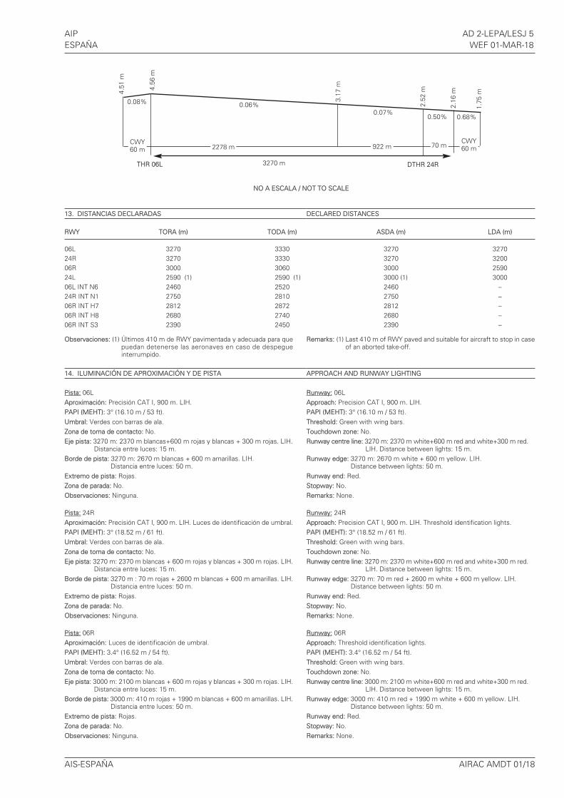
13. DISTANCIAS DECLARADAS
Observaciones: (1) Últimos 410 m de RWY pavimentada y adecuada para quepuedan detenerse las aeronaves en caso de despegueinterrumpido.
14. ILUMINACIÓN DE APROXIMACIÓN Y DE PISTA
Pista: 06LAproximación: Precisión CAT I, 900 m. LIH.PAPI (MEHT): 3° (16.10 m / 53 ft).Umbral: Verdes con barras de ala.Zona de toma de contacto: No.Eje pista: 3270 m: 2370 m blancas+600 m rojas y blancas + 300 m rojas. LIH.
Distancia entre luces: 15 m.Borde de pista: 3270 m: 2670 m blancas + 600 m amarillas. LIH.
Distancia entre luces: 50 m.Extremo de pista: Rojas.Zona de parada: No.Observaciones: Ninguna.
Pista: 24RAproximación: Precisión CAT I, 900 m. LIH. Luces de identificación de umbral.PAPI (MEHT): 3° (18.52 m / 61 ft).Umbral: Verdes con barras de ala.Zona de toma de contacto: No.Eje pista: 3270 m: 2370 m blancas + 600 m rojas y blancas + 300 m rojas. LIH.
Distancia entre luces: 15 m.Borde de pista: 3270 m : 70 m rojas + 2600 m blancas + 600 m amarillas. LIH.
Distancia entre luces: 50 m.Extremo de pista: Rojas.Zona de parada: No.Observaciones: Ninguna.
Pista: 06RAproximación: Luces de identificación de umbral.PAPI (MEHT): 3.4° (16.52 m / 54 ft).Umbral: Verdes con barras de ala.Zona de toma de contacto: No.Eje pista: 3000 m: 2100 m blancas + 600 m rojas y blancas + 300 m rojas. LIH.
Distancia entre luces: 15 m.Borde de pista: 3000 m: 410 m rojas + 1990 m blancas + 600 m amarillas. LIH.
Distancia entre luces: 50 m.Extremo de pista: Rojas.Zona de parada: No.Observaciones: Ninguna.
DECLARED DISTANCES
Remarks: (1) Last 410 m of RWY paved and suitable for aircraft to stop in caseof an aborted take-off.
APPROACH AND RUNWAY LIGHTING
Runway: 06LApproach: Precision CAT I, 900 m. LIH.PAPI (MEHT): 3° (16.10 m / 53 ft).Threshold: Green with wing bars.Touchdown zone: No.Runway centre line: 3270 m: 2370 m white+600 m red and white+300 m red.
LIH. Distance between lights: 15 m.Runway edge: 3270 m: 2670 m white + 600 m yellow. LIH.
Distance between lights: 50 m.Runway end: Red.Stopway: No.Remarks: None.
Runway: 24RApproach: Precision CAT I, 900 m. LIH. Threshold identification lights.PAPI (MEHT): 3° (18.52 m / 61 ft).Threshold: Green with wing bars.Touchdown zone: No.Runway centre line: 3270 m: 2370 m white+600 m red and white+300 m red.
LIH. Distance between lights: 15 m.Runway edge: 3270 m: 70 m red + 2600 m white + 600 m yellow. LIH.
Distance between lights: 50 m.Runway end: Red.Stopway: No.Remarks: None.
Runway: 06RApproach: Threshold identification lights.PAPI (MEHT): 3.4° (16.52 m / 54 ft).Threshold: Green with wing bars.Touchdown zone: No.Runway centre line: 3000 m: 2100 m white+600 m red and white+300 m red.
LIH. Distance between lights: 15 m.Runway edge: 3000 m: 410 m red + 1990 m white + 600 m yellow. LIH.
Distance between lights: 50 m.Runway end: Red.Stopway: No.Remarks: None.
THR 06L
0.06%0.07%
0.50% 0.68%
70 m
3270 m
4.51
m
4.56
m
3.17
m
0.08% 2.52
m
2.16
m
1.75
m
2278 m 922 mCWY60 m
DTHR 24R
CWY60 m
NO A ESCALA / NOT TO SCALE
RWY TORA (m) TODA (m) ASDA (m) LDA (m)
06L 3270 3330 3270 327024R 3270 3330 3270 320006R 3000 3060 3000 259024L 2590 (1) 2590 (1) 3000 (1) 300006L INT N6 2460 2520 2460 –24R INT N1 2750 2810 2750 –06R INT H7 2812 2872 2812 –06R INT H8 2680 2740 2680 –06R INT S3 2390 2450 2390 –
AD 2-LEPA/LESJ 6 AIPWEF 01-MAR-18 ESPAÑA
AIRAC AMDT 01/18 AIS-ESPAÑA
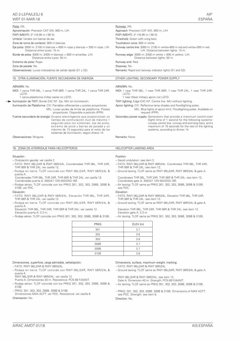
Pista: 24LAproximación: Precisión CAT II/III, 900 m, LIH.PAPI (MEHT): 3° (16.95 m / 56 ft).Umbral: Verdes con barras de ala.Zona de toma de contacto: 900 m blancas.Eje pista: 3000 m: 2100 m blancas + 600 m rojas y blancas + 300 m rojas. LIH.
Distancia entre luces: 15 m.Borde de pista: 3000 m: 2400 m blancas + 600 m amarillas. LIH.
Distancia entre luces: 50 m.Extremo de pista: Rojas.Zona de parada: No.Observaciones: Luces indicadoras de salida rápida (S1 y S2).
15. OTRA ILUMINACIÓN, FUENTE SECUNDARIA DE ENERGÍA
ABN/IBN: No.WDI: 1 cerca THR 06L, 1 cerca THR 06R, 1 cerca THR 24L, 1 cerca THR 24R.
LGTD.1 cerca plataforma militar oeste no LGTD.
Iluminación de TWY: Borde EXC N7. Eje. MU sin iluminación.Iluminación de Plataforma: CIV: Pantallas reflectantes y postes proyectores.
MIL: Luces azules de límite de plataforma. Postesproyectores. Disponible a petición (PPR).
Fuente secundaria de energía: Grupos electrógenos que proporcionan untiempo de conmutación (luz) de máximo 1segundo para los sistemas: eje de pista,extremo de pista y barras de parada y unmáximo de 15 segundos para el resto de lossistemas de iluminación, según Anexo 14.
Observaciones: Ninguna.
16. ZONA DE ATERRIZAJE PARA HELICÓPTEROS
Situación: – Ondulación geoide: ver casilla 2. – FATO: RWY 06L/24R & RWY 06R/24L. Coordenadas THR 06L, THR 24R,
THR 06R & THR 24L: ver casilla 12. – Rodaje en tierra: TLOF coincide con RWY 06L/24R, RWY 06R/24L &
puerta A.Coordenadas THR 06L, THR 24R, THR 06R & THR 24L: ver casilla 12. Coordenadas puerta A: 393247.12N 0024253.16E.
– Rodaje aéreo: TLOF coincide con los PRKG 301, 302, 303, 308B, 309B &310B: ver PDC.
Elevación: – FATO: RWY 06L/24R & RWY 06R/24L. Elevación THR 06L, THR 24R,
THR 06R & THR 24L: ver casilla 12.– Rodaje en tierra: TLOF coincide con RWY 06L/24R, RWY 06R/24L &
puerta A.Elevación THR 06L, THR 24R, THR 06R & THR 24L: ver casilla 12.Elevación puerta A: 3.3 m.
– Rodaje aéreo: TLOF coincide con PRKG 301, 302, 303, 308B, 309B & 310B.
Dimensiones, superficie, carga admisible, señalización: – FATO: RWY 06L/24R & RWY 06R/24L.– Rodaje en tierra: TLOF coincide con RWY 06L/24R, RWY 06R/24L &
puerta A.RWY 06L/24R & RWY 06R/24L: ver casilla 12.Puerta A: Dimensiones 40 m. Resistencia: PCN 89 F/A/W/T.
– Rodaje aéreo: TLOF coincide con los PRKG 301, 302, 303, 308B, 309B &310B.
– PRKG: 301, 302, 303, 308B, 309B & 310B.Dimensiones MAX ACFT: ver PDC. Resistencia: ver casilla 8.
Orientación: No.
Runway: 24LApproach: Precision CAT II/III, 900 m, LIH. PAPI (MEHT): 3° (16.95 m / 56 ft).Threshold: Green with wing bars.Touchdown zone: 900 m white.Runway centre line: 3000 m: 2100 m white+600 m red and white+300 m red.
LIH. Distance between lights: 15 m.Runway edge: 3000 m: 2400 m white + 600 m yellow. LIH.
Distance between lights: 50 m.Runway end: Red.Stopway: No.Remarks: Rapid exit taxiway indicator lights (S1 and S2).
OTHER LIGHTING, SECONDARY POWER SUPPLY
ABN/IBN: No.WDI: 1 near THR 06L, 1 near THR 06R, 1 near THR 24L, 1 near THR 24R.
LGTD. 1 near West military apron not LGTD.
TWY lighting: Edge EXC N7. Centre line. MU without lighting.Apron lighting: CIV: Reflective lamp shades and floodlighting poles.
MIL: Blue lights of apron limit. Floodlighting poles. Available onrequest (PPR).
Secondary power supply: Generators that provide a maximum switch-over(light) time of 1 second for the following systems:runway centre line, runway end and stop bars, and amaximum of 15 seconds for the rest of the lightingsystems, according to Annex 14.
Remarks: None.
HELICOPTER LANDING AREA
Position:– Geoid undulation: see item 2.– FATO: RWY 06L/24R & RWY 06R/24L. Coordinates THR 06L, THR 24R,
THR 06R & THR 24L: see item 12. – Ground taxiing: TLOF same as RWY 06L/24R, RWY 06R/24L & gate A.
Coordinates THR 06L, THR 24R, THR 06R & THR 24L: see item 12.Coordinates gate A: 393247.12N 0024253.16E.
– Air taxiing: TLOF same as PRKG 301, 302, 303, 308B, 309B & 310B:see PDC.
Elevation:– FATO: RWY 06L/24R & RWY 06R/24L. Elevation THR 06L, THR 24R,
THR 06R & THR 24L: see item 12.– Ground taxiing: TLOF same as RWY 06L/24R, RWY 06R/24L & gate A.
Elevation THR 06L, THR 24R, THR 06R & THR 24L: see item 12.Elevation gate A: 3.3 m.
– Air taxiing: TLOF same as PRKG 301, 302, 303, 308B, 309B & 310B.
Dimensions, surface, maximum weight, marking:– FATO: RWY 06L/24R & RWY 06R/24L– Ground taxiing: TLOF same as RWY 06L/24R, RWY 06R/24L & gate A.
RWY 06L/24R & RWY 06R/24L: see item 12.Gate A: Dimension 40 m. Strength: PCN 89 F/A/W/T.
– Air taxiing: TLOF same as PRKG 301, 302, 303, 308B, 309B & 310B.
– PRKG: 301, 302, 303, 308B, 309B & 310B. Dimensions of MAX ACFT:see PDC. Strength: see item 8.
Direction: No.
PRKG ELEV (m)
301 3.7
302 3.6
303 3.8
308B 3.7
309B 3.7
310B 3.6
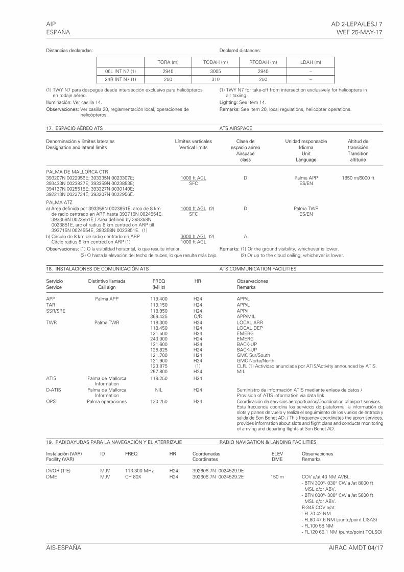
AIP AD 2-LEPA/LESJ 7ESPAÑA WEF 25-MAY-17
Distancias declaradas: Declared distances:
(1) TWY N7 para despegue desde intersección exclusivo para helicópteros (1) TWY N7 for take-off from intersection exclusively for helicopters inen rodaje aéreo. air taxiing.
Iluminación: Ver casilla 14. Lighting: See item 14.Observaciones: Ver casilla 20, reglamentación local, operaciones de Remarks: See item 20, local regulations, helicopter operations.
helicópteros.
17. ESPACIO AÉREO ATS ATS AIRSPACE
Denominación y límites laterales Límites verticales Clase de Unidad responsable Altitud deDesignation and lateral limits Vertical limits espacio aéreo Idioma transición
Airspace Unit Transitionclass Language altitude
PALMA DE MALLORCA CTR393207N 0022956E; 393335N 0023307E; 1000 ft AGL D Palma APP 1850 m/6000 ft393433N 0023827E; 393359N 0023853E; SFC ES/EN394137N 0025518E; 393327N 0030140E;392213N 0023734E; 393207N 0022956E.
PALMA ATZa) Área definida por 393358N 0023851E, arco de 8 km 1000 ft AGL (2) D Palma TWR
de radio centrado en ARP hasta 393715N 0024554E, SFC ES/EN393358N 0023851E / Area defined by 393358N0023851E, arc of radius 8 km centred on ARP till393715N 0024554E, 393358N 0023851E. (1)
b) Círculo de 8 km de radio centrado en ARP 3000 ft AGL (2) ACircle radius 8 km centred on ARP (1) 1000 ft AGL
Observaciones: (1) O la visibilidad horizontal, lo que resulte inferior. Remarks: (1) Or the ground visibility, whichever is lower.(2) O hasta la elevación del techo de nubes, lo que resulte más bajo. (2) Or up to the cloud ceiling, whichever is lower.
18. INSTALACIONES DE COMUNICACIÓN ATS ATS COMMUNICATION FACILITIES
Servicio Distintivo llamada FREQ HR ObservacionesService Call sign (MHz) Remarks
APP Palma APP 119.400 H24 APP/LTAR 119.150 H24 APP/LSSR/SRE 118.950 H24 APP/I
369.425 O/R APP/MILTWR Palma TWR 118.300 H24 LOCAL ARR
118.450 H24 LOCAL DEP121.500 H24 EMERG243.000 H24 EMERG121.600 H24 BACK-UP125.825 H24 BACK-UP121.700 H24 GMC Sur/South121.900 H24 GMC Norte/North123.875 (1) CLR. (1) Actividad anunciada por ATIS/Activity announced by ATIS.257.800 H24 MIL
ATIS Palma de Mallorca 119.250 H24Information
D-ATIS Palma de Mallorca NIL H24 Suministro de información ATIS mediante enlace de datos / Information Provision of ATIS information via data link.
OPS Palma operaciones 130.250 H24 Coordinación de servicios aeroportuarios/Coordination of airport services.Esta frecuencia coordina los servicios de plataforma, la información deslots y planes de vuelo y realiza el seguimiento de los vuelos de entrada ysalida de Son Bonet AD. / This frequency coordinates the apron services,provides information about slots and flight plans and conducts monitoringof arriving and departing flights at Son Bonet AD.
19. RADIOAYUDAS PARA LA NAVEGACIÓN Y EL ATERRIZAJE RADIO NAVIGATION & LANDING FACILITIES
Instalación (VAR) ID FREQ HR Coordenadas ELEV ObservacionesFacility (VAR) Coordinates DME Remarks
DVOR (1ºE) MJV 113.300 MHz H24 392606.7N 0024529.9EDME MJV CH 80X H24 392606.7N 0024529.2E 150 m COV a/at 40 NM AVBL:
- BTN 300°- 030° CW a /at 8000 ftMSL o/or ABV.
- BTN 030°- 300° CW a /at 5000 ftMSL o/or ABV.
R-345 COV a/at:- FL70 42 NM - FL80 47.6 NM (punto/point LISAS)- FL100 58 NM- FL120 66.1 NM (punto/point TOLSO)
AIS-ESPAÑA AIRAC AMDT 04/17
TORA (m) TODAH (m) RTODAH (m) LDAH (m)
06L INT N7 (1) 2945 3005 2945 –
24R INT N7 (1) 250 310 250 –
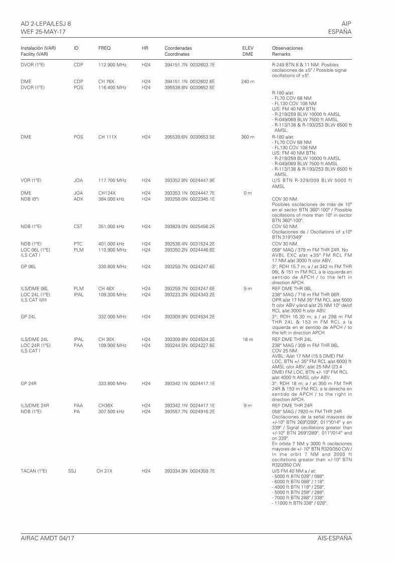
Instalación (VAR) ID FREQ HR Coordenadas ELEV ObservacionesFacility (VAR) Coordinates DME Remarks
DVOR (1ºE) CDP 112.900 MHz H24 394151.7N 0032603.7E R-249 BTN 8 & 11 NM: Posibles oscilaciones de ±5º / Possible signaloscillations of ±5º.
DME CDP CH 76X H24 394151.1N 0032602.6E 240 mDVOR (1ºE) POS 116.400 MHz H24 395538.8N 0030652.5E
R-180 a/at:- FL70 COV 68 NM- FL130 COV 108 NMU/S: FM 40 NM BTN:- R-219/259 BLW 10000 ft AMSL- R-049/069 BLW 7500 ft AMSL- R-113/138 & R-193/253 BLW 6500 ftAMSL.
DME POS CH 111X H24 395539.6N 0030653.5E 360 m R-180 a/at:- FL70 COV 68 NM- FL130 COV 108 NMU/S: FM 40 NM BTN:- R-219/259 BLW 10000 ft AMSL- R-049/069 BLW 7500 ft AMSL- R-113/138 & R-193/253 BLW 6500 ftAMSL.
VOR (1ºE) JOA 117.700 MHz H24 393352.8N 0024447.9E U/S BTN R-329/009 BLW 5000 ftAMSL
DME JOA CH124X H24 393353.1N 0024447.7E 0 mNDB (0º) ADX 384.000 kHz H24 393258.0N 0022345.1E COV 30 NM.
Posibles oscilaciones de más de 10ºen el sector BTN 360º-100º / Possibleoscillations of more than 10º in sectorBTN 360º-100º.
NDB (1ºE) CST 351.000 kHz H24 393829.0N 0025456.2E COV 50 NM.Oscilaciones de / Oscillations of ±10º BTN 319º/349º
NDB (1ºE) PTC 401.000 kHz H24 392538.4N 0031524.2E COV 30 NM.LOC 06L (1ºE) PLM 110.900 MHz H24 393350.2N 0024446.6E 058° MAG / 379 m FM THR 24R. No ILS CAT I AVBL EXC a/at ±35º FM RCL FM
17 NM a/at 3000 ft o/or ABV.GP 06L 330.800 MHz H24 393259.7N 0024247.6E 3°; RDH 15.7 m; a / at 342 m FM THR
06L & 151 m FM RCL a la izquierda ensentido de APCH / to the left indirection APCH.
ILS/DME 06L PLM CH 46X H24 393259.7N 0024247.6E 9 m REF DME THR 06LLOC 24L (1ºE) IPAL 109.300 MHz H24 393223.3N 0024343.2E 238° MAG / 718 m FM THR 06R. ILS CAT II/III OPR a/at 17 NM 35º FM RCL a/at 5000
ft o/or ABV y/and a/at 25 NM 10º de/ofRCL a/at 3000 ft o/or ABV.
GP 24L 332.000 MHz H24 393309.9N 0024534.2E 3°; RDH 16.30 m; a / at 298 m FMTHR 24L & 153 m FM RCL a laizquierda en el sentido de APCH / tothe left in direction APCH.
ILS/DME 24L IPAL CH 30X H24 393309.8N 0024534.2E 18 m REF DME THR 24LLOC 24R (1ºE) PAA 109.900 MHz H24 393244.5N 0024227.6E 238° MAG / 309 m FM THR 06LILS CAT I COV 25 NM.
AVBL: A/at 17 NM (15.5 DME) FMLOC, BTN +/- 35º FM RCL a/at 6000 ftAMSL o/or ABV; a/at 25 NM (23.4DME) FM LOC, BTN +/- 10º FM RCLa/at 4000 ft AMSL o/or ABV.
GP 24R 333.800 MHz H24 393342.1N 0024417.1E 3°; RDH 18 m; a / at 350 m FM THR24R & 153 m FM RCL a la derecha ensentido de APCH / to the right indirection APCH.
ILS/DME 24R PAA CH36X H24 393342.1N 0024417.1E 9 m REF DME THR 24RNDB (1ºE) PA 307.500 kHz H24 393557.7N 0024916.2E 058° MAG / 7920 m FM THR 24R
Oscilaciones de la señal mayores de+/-10º BTN 269º/289º, 011º/014º y en339º / Signal oscillations greater than+/-10º BTN 269º/289º, 011º/014º andon 339º.En órbita 7 NM y 3000 ft oscilacionesmayores de +/- 10º BTN R320/350 CW /In the orbit 7 NM and 3000 ftoscillations greater than +/-10º BTNR320/350 CW.
TACAN (1ºE) SSJ CH 21X H24 393334.9N 0024359.7E U/S FM 40 NM a / at:- 5000 ft BTN 028º / 088º.- 6000 ft BTN 088º / 118º.- 4000 ft BTN 118º / 258º.- 5000 ft BTN 258º / 288º.- 7000 ft BTN 288º / 338º.- 11000 ft BTN 338º / 028º.
AIRAC AMDT 04/17 AIS-ESPAÑA
AD 2-LEPA/LESJ 8 AIPWEF 25-MAY-17 ESPAÑA
AIP AD 2-LEPA/LESJ 9ESPAÑA WEF 22-JUN-17
LOCAL REGULATIONS
1. AIRPORT REGULATION
1.1. RESTRICTIONS TO OPERATIONS
From May 1st until October 31st, the use of the airport shall be restricted foraircraft with a cruising speed lower than 220 kt (except State, hospital andsearch and rescue aircraft), daily from 0530 to 0700 and 1600 to 1830.
If any affected aircraft requires the use of the airport during these periods, itshall assume the possible delays, as not restricted aircraft will always havepriority.
Due to General Aviation apron limited capacity, from April 1st until September30th, all the General Aviation and Corporative Aviation traffics which want tooperate in the airport, must include in their messages or request for slot thedata corresponding to the arrival and the departure flights. The slot requestshall be understood as not authorized until the reception of the confirmedcoordination. The coordination request must include: aircraft registrationnumber, ICAO code, length and wingspan.
In case of lack of capacity in the apron, it should may coordinate flights with amaximum stay of 3 hours, in order to unload passengers and refuelling of theaircraft, but at least one member of the crew shall stay inside the aircraft.
Flights without previous coordination requested, shall be coordinated onarrival, subject in every case to the capacity available.
1.2. DIVERTING
All flights which, by any cause, deviate to the airport, shall notify the cause ofthis matter to the Air Navigation Services whom, in turn, shall transmit it toCEOPS of the airport.
1.3. GENERAL AVIATION AND BUSINESS
It is mandatory to contract handling agent for all operation to General andBusiness Aviation, by virtue of provisions in item 3.1.6 of AD 1.1 of the AIP-Spain.
1.4. FOREIGN STATE AIRCRAFT
PPR request is mandatory 24 hours in advance. When transporting dangerousgoods it shall be requested at least two working days in advance.
2. GROUND MOVEMENT
Collision avoidance with other aircraft or obstacles is a responsibility of:• Pilots taxiing in the apron and in the area not visible from TWR.
• Handling companies during push-back manoeuvring or exiting the stand.
2.1. APRON
a) It is forbidden to cross the taxiways in the apron on foot. Access to theaircraft on foot will only be possible if parked in a stand next to the terminalbuilding. Access to the rest of stands shall be made by vehicle.
b) Neither the arrival nor the permanence of any code letter F aircraft will beauthorized without the previous airport authority permission.
c) On every stand equipped with 400 Hz system supply:
• It is mandatory the use of the 400 Hz system.• The use of aircraft APU (Auxiliary Power Unit) is forbidden for the period
with 2 minutes after blocks-on for arrivals and 5 minutes before offblocksfor departures.
• The aircraft APU (Auxiliary Power Unit) will only be used when neither the400 Hz system nor the mobile units are operative, or when the airconditioning service is required and it is not available.
• The use of a harness hook is recommended for fastening of the 400 Hzhosepipe of the system to the aircraft. Otherwise, the airport authoritywill not accept responsibility for any damages the aircraft could suffer.
d) When it is necessary to connect the 400 Hz system before an aircraft turnoff the engines, either due to the aircraft APU (Auxiliary Power Unit) is notoperational or a company procedure with prior permission of the airportauthority:• The flight coordinator shall ascertain that the aircraft is totally stopped and
confirm it by means of signals with the pilot in charge of the aircraft (RCA,Appendix C, Adjunct 5) before the blocks will be on.
• Any operation shall not be carried out until the blocks will be on.
20. REGLAMENTACIÓN LOCAL
1. REGLAMENTACIÓN AEROPORTUARIA
1.1. RESTRICCION A LAS OPERACIONES
Desde el 01 de mayo hasta el 31 de octubre, diariamente de 0530 a 0700 y de1600 a 1830, las aeronaves cuya velocidad de crucero sea inferior a 220 kt(excepto aeronaves de estado, hospitales y salvamento) tendrán restringido eluso del aeropuerto.
Las aeronaves afectadas que soliciten el uso del aeropuerto durante el horariocitado, asumirán las posibles demoras, ya que las aeronaves no restringidastendrán prioridad sobre ellas.
Debido a la capacidad limitada de la plataforma de Aviación General, desde el01 de abril hasta el 30 de septiembre, en todos los mensaje o solicitudes deslot correspondientes a tráficos de Aviación General y Aviación Corporativa que deseen operar en el aeropuerto, deberán incluirse tanto los datos del vuelo de llegada como del de salida. Hasta recibir confirmación de lacoordinación, se entenderá que la petición solicitada no ha sido autorizada. Laspeticiones de coordinación deberán incluir: matrícula, código OACI de laaeronave, longitud y envergadura.
En caso de falta de capacidad de la plataforma, se podrán coordinar vuelos conuna permanencia máxima de 3 horas para desembarque de personal yreabastecimiento de la aeronave, debiendo permanecer algún miembro de latripulación en la aeronave.
Los vuelos que no hayan solicitado coordinación previa, deberán sercoordinados a su llegada y siempre sujetos a la capacidad disponible.
1.2. DESVÍO DE VUELOS
Todos los vuelos que, por cualquier motivo, se desvíen al aeropuerto, deberáncomunicar los motivos del mismo a los Servicios de Navegación Aérea, quien asu vez los transmitirá al CEOPS del aeropuerto.
1.3. AVIACIÓN GENERAL Y DE NEGOCIOS
Todas las aeronaves de Aviación General y de Negocios, deberán contratar losservicios de asistencia en tierra, en virtud de lo establecido en el punto 3.1.6del AD 1.1 del AIP-España.
1.4. AERONAVES DE ESTADO EXTRANJERAS
La solicitud PPR es obligatoria con 24 horas de antelación. En caso detransporte de mercancías peligrosas se realizará con al menos dos díaslaborables de antelación.
2. MOVIMIENTO EN SUPERFICIE
Evitar colisiones con otra aeronaves y obstáculos es responsabilidad de:• Los pilotos en el rodaje en plataforma y en las zonas de plataforma no
visibles desde TWR.• Las compañías de asistencia en tierra durante la maniobra de retroceso o
salida del puesto de estacionamiento.
2.1. PLATAFORMA
a) Se prohibe cruzar a pie las calles de rodaje en plataforma. Solamente sepodrá acceder a pie a las aeronaves estacionadas en posiciones próximas aledificio terminal. En el resto de posiciones, las tripulaciones se deberántrasladar en vehículo.
b) No se autoriza ni la llegada ni la permanencia de aeronaves de letra clave F,si no es con la autorización previa del aeropuerto.
c) En todos los puestos de estacionamiento dotados de instalaciones desuministro de corriente de 400 Hz:• Es obligatorio el uso de la instalación de 400 Hz.• El uso del APU (Unidad Auxiliar de Potencia) del avión está prohibido
dentro del periodo comprendido entre 2 minutos después de calzos a lallegada y 5 minutos antes de la retirada de calzos a la salida.
• La APU (Unidad Auxiliar de Potencia) del avión solo podrá utilizarsecuando no estén operativas ni la instalación de 400 Hz ni las unidadesmóviles o cuando se requiera el servicio de aire acondicionado y no estédisponible el equipamiento.
• Es recomendable la utilización del gancho de sujeción de la manguera dela instalación de 400 Hz a la aeronave. En caso de no utilizar dicho gancho,el aeropuerto no se hace responsable de las afecciones que pueda sufrirla aeronave.
d) Cuando sea preciso conectar la instalación de 400 Hz antes de que unaaeronave pare motores, porque la APU (Unidad Auxiliar de Potencia) delavión esté no operativa o por procedimiento de la compañía autorizado por elaeropuerto:• El coordinador de vuelo se asegurará de que la aeronave esté totalmente
detenida y lo confirmará mediante señales con el comandante de laaeronave (RCA, Apéndice C, Adjunto 5) antes de que se proceda a lapuesta de calzos.
• Ninguna actuación se llevará a cabo hasta que no se hayan puestocalzos.
AIS-ESPAÑA AIRAC AMDT 06/17
AD 2-LEPA/LESJ 10 AIPWEF 24-MAY-18 ESPAÑA
e) En los estacionamientos remotos que no tienen instalación de 400 Hz, seprohíbe la utilización de la APU (Unidad Auxiliar de Potencia) durante elhorario nocturno, (ver casilla 21), excepto aeronaves que tengan autorizada lapuesta en marcha de motores y el rodaje.
2.2. PROCEDIMIENTO DE PUESTA EN MARCHA
Las aeronaves deberán estar completamente listas para la puesta en marchaantes de llamar en la frecuencia de Autorizaciones. Las aeronaves realizaránuna única llamada a Palma Autorizaciones en la frecuencia CLR, en el rango de± 5 minutos respecto su TOBT, para:• Solicitar autorización de puesta en marcha e informar de la necesidad de
realizar arranque cruzado si así fuese requerido, • Informar del tipo y serie de aeronave, puesto de estacionamiento y del
mensaje ATIS recibido,• Solicitar información de demora para la puesta en marcha,• Recibir Autorización ATC e• Informar de posibles restricciones para cumplir la reglamentación local
(equipamiento RNAV, performance al despegue, etc).
De ser posible, Palma Autorizaciones emitirá la autorización de puesta enmarcha junto con la Autorización ATC. En caso de no ser posible, el CLRanotará la solicitud de puesta en marcha en el sistema A-CDM y procederá aautorizar la misma cuando la TSAT lo permita. La anotación de la solicitud depuesta en marcha en el sistema equivale a la solicitud de mensaje de listo parasalir (REA) para vuelos regulados con CTOT.
En caso de no cumplir parámetros A-CDM, ATC no anotará la solicitud depuesta en marcha y el piloto deberá contactar con su coordinador de vuelo paracorregir parámetros A-CDM. Palma Autorizaciones no facilitará informaciónsobre incumplimientos del proceso A-CDM para evitar sobrecargar lafrecuencia.
Para evitar saturar la frecuencia CLR los pilotos se abstendrán de realizarllamadas sucesivas antes de recibir la llamada de Palma Autorizaciones paraaprobar su puesta en marcha conforme a la TSAT actualizada.
Si 5 minutos después de TOBT, Palma Autorizaciones no ha recibido peticiónde puesta en marcha, el vuelo perderá su TSAT y no se podrá autorizar supuesta en marcha. Será necesario recibir una nueva TOBT y EOBT actualizadaspara que el vuelo sea secuenciado nuevamente y reciba una nueva TSAT. Laactualización de TOBT y/o EOBT solo puede ser realizada por la compañía aéreao su agente de asistencia en tierra, por lo que los pilotos se abstendrán derealizar peticiones a ATC en este sentido.
La petición de retroceso deberá ser solicitada en la frecuencia GMCcorrespondiente y comenzar antes de 5 minutos desde la recepción de laautorización de puesta en marcha. La autorización de retroceso sólo puededarla GMC.
En la maniobra de puesta en marcha con GPU o APU externa, las aeronavessolicitarán autorización de arranque cruzado junto con la autorización delretroceso en frecuencia de rodadura y posteriormente pondrán en marcha unmotor, harán la maniobra de retroceso manteniendo potencia a ralentí, y unavez posicionadas en la calle de rodaje en plataforma podrán incrementar lapotencia lo estrictamente necesario para poner en marcha el resto de motores.
2.3. PROCEDIMIENTOS DE RODAJE
Para optimizar la gestión de la plataforma en momentos de alta demanda detráfico, se define una zona denominada GMC-C (ver plano PDC para mayordetalle) que, dependiendo del momento, puede ser gestionada bien por GMC-N, bien por GMC-S.
A. AERONAVES DE SALIDALos pilotos contactarán con Palma Rodadura (GMC, GMC-N, GMC-S)correspondiente (ver casilla 18), según indique CLR para solicitar permiso deretroceso remolcado y/o rodaje.Las aeronaves deben estar listas para retroceso remolcado o rodaje dentro delos 5 minutos siguientes a la hora aprobada de puesta en marcha. En casocontrario el piloto deberá informar a ATC.En caso de detectar un retroceso de aeronave incorrecto, GMC solicitará alcomandante que vuelva a estacionar la aeronave en la posición inicial.En caso de que el comandante desee solicitar un retroceso que no siganinguno de los procedimientos publicados, deberá contactar con GMCcorrespondiente quien enviará a un vehículo “SÍGAME” para supervisar laoperación. El vehículo “SÍGAME” comunicará al coordinador de vuelo elsentido del retroceso.GMC podrá aprobar retrocesos publicados que correspondan a laconfiguración contraria a la pista en uso, informando al piloto de hacia quédirección tiene que aproar. El vehículo “SÍGAME” comunicará al coordinadorde vuelo el sentido del retroceso.Se prohíbe en toda la plataforma la utilización de la reversa para la operaciónde retroceso.
B. AERONAVES DE LLEGADALas aeronaves, después de abandonar la pista en caso de no recibirinstrucciones de rodaje, mantendrán la posición cortos de TWYNORTH/SOUTH y esperarán instrucciones del ATC para continuar rodaje alpuesto de estacionamiento.En caso de estar operativos GMC-N y GMC-S, si la aeronave no consigueestablecer comunicación con el GMC al que ha sido transferido, mantendráposición en el primer punto de espera intermedio que se encuentre en su rutade rodaje.
e) On the remote stands without 400 Hz system, the use of APU (AuxiliaryPower Unit) is forbidden during the night hours, (see item 21), except foraircraft cleared to start-up engines and taxiing.
2.2. START-UP PROCEDURE
Aircraft must be completely ready for start-up prior to making the call on theClearance frequency. Aircraft shall make a single call to Palma Clearance onthe CLR frequency within ±5 minutes of their TOBT to:
• Request start-up clearance and report the need for cross start-up ifnecessary,
• Indicate the aircraft type and series, stand and ATIS message received,
• Request delay information for start-up,• Receive ATC Clearance and• Report possible restrictions in complying with local regulations (RNAV
equipment, take-off performance, etc.).
If possible, Palma Clearance shall issue the start-up clearance along with theATC Clearance. If not possible, CLR will enter the start-up request in the A-CDM system and will authorise such when the T-SAT so allows. The start-up request entry in the system is equivalent to the ready to departmessage (REA) for flights regulated with CTOT.
If the A-CDM parameters are not met, ATC will not enter the start-up requestand the pilot must contact the flight coordinator to correct the A-CDMparameters. Palma Clearance shall not provide information on non-compliancein the A-CDM process, to prevent frequency overload.
To avoid saturating the CLR frequency, pilots shall refrain from makingsuccessive calls prior to receiving the call from Palma Clearance to approvestart-up in accordance with the updated TSAT.
If Palma Clearance has not received the start-up request within 5 minutes ofTOBT, the flight will miss its TSAT and start-up will not be cleared. Newupdated TOBT and EOBT must be received for the flight to be sequencedagain and to receive a new TSAT. The TOBT and/or EOBT may only beupdated by the air carrier or the ground handling agent, so pilots shall refrainfrom making those requests to ATC.
The push-back request must be submitted on the corresponding (GMC)frequency and begin within 5 minutes after the receipt of start-up clearance.Push-back clearance is given by GMC only.
In the start-up manoeuvre with external GPU or APU, aircraft shall requestcross start-up clearance together with the push-back clearance on the taxiingfrequency and then start-up one engine. They must complete the push-backmanoeuvre at idle power, and once positioned on the taxiway on the apron,they may increase power as strictly necessary to start the rest of the engines.
2.3. TAXIING PROCEDURES
To optimise apron management at times of high traffic demand, a zone calledGMC-C is defined (see the PDC for more detail), which will be managed atdifferent times either by GMC-N or GMC-S.
A. DEPARTING AIRCRAFTPilots shall contact the corresponding Palma Ground (GMC, GMC-N, GMC-S)(see item 18) to request permission for towed push-back and/or taxiing.
The aircraft must be ready to be pushed back by towing or taxiing no later than5 minutes after the time approved for the start-up. Otherwise the pilot mustnotify ATC.Whenever an incorrect push-back of aircraft is detected, GMC shall requestthe pilot to park the aircraft in the initial position again.Whenever the pilot wishes to request a push-back that does not follow any ofthe published procedures, should contact the corresponding GMC who willsend a “FOLLOW ME” vehicle to oversee the operation. The “FOLLOW ME”vehicle shall communicate to the flight coordinator the push-back direction.
GMC may approve the published push-back corresponding to the oppositeconfiguration to the runway in use, reporting the pilot which direction has tonose to. The “FOLLOW ME” vehicle shall communicate to the flightcoordinator the push-back direction.The use of the reverse power is forbidden in the whole apron for thebackward operation.
B. ARRIVING AIRCRAFTIf no taxiing instructions are received, aircraft shall hold short position of theNORTH/SOUTH TWY after vacating the runway and expect ATC taxiinginstructions in order to continue taxiing up to the parking position.
When GMC-N and GMC-S are operational, if the aircraft does not manage toestablish communication with the GMC to which it has been transferred, itshall hold at the first intermediate holding position along its taxiing route.
AIRAC AMDT 04/18 AIS-ESPAÑA
Únicamente se prestará el servicio de guiado mediante vehículo “SÍGAME” alos puestos de estacionamiento de Aviación General y en las que el sistema deguía de atraque visual esté U/S.
También se realizará el servicio de guiado tanto a petición de TWR, como arequerimiento del piloto o en casos excepcionales.
Las aeronaves que se dirijan a los PRKG comprendidos entre el 30 y el 48,entrarán, preferentemente, por la TWY V1 y mantendrán corto del punto deespera intermedio.
ATC autorizará, siempre que sea posible, la entrada directa a estos puestos deestacionamiento por la TWY V2.
Es de especial importancia que las aeronaves antes de acceder a la plataformaextremen su atención al tráfico existente en las calles de rodaje. Las aeronavesque efectúen el rodaje por plataforma lo realizarán a una velocidad tal queproporcione un tiempo de reacción lo suficientemente elevado como paraprevenir frenazos bruscos. En las vías de servicio próximas a las puertas F, G, Ky M, como áreas especialmente críticas se debe prestar una especial atencióna la velocidad del tráfico de manera que sea la adecuada para poder detenersede forma segura ante cualquier incidencia que pudiera acontecer en su camino.
2.4. RUTAS DE RODAJE NORMALIZADAS
2.4.1. CONFIGURACIÓN ESTE
A) LLEGADAS POR RWY 06L
• R-1 a R-6, R-7 (PRKG 24, 25 y 114 a 117): Ruta estándar: N3, N2, N1 ofinal de pista, TWY NORTH.- PRKG 301-303 (helicópteros): ver casilla 20. Reglamentación local,Operación de helicópteros.
- PRKG 306 (aeronaves de letra de clave F): ver casil la 20.Reglamentación local, Operación de aeronaves de letra de clave F.
- PRKG 303 (aviones), 306 (aeronaves de letra de clave E o inferior) y 307-310: Ruta estándar, puerta A y TWY LA.
- PRKG 311-315: Ruta estándar, puerta A y TWY LB.- PRKG 316-318: Ruta estándar, puerta B y TWY LC.- PRKG 1-6 y 100-103B: Ruta estándar, puerta C y TWY LD, EXC PRKG103: Ruta estándar, puerta D y TWY LD.
- PRKG 8-22: Ruta estándar, puerta D y TWY LE.- PRKG 104-109: Ruta estándar, puerta E y TWY W5.- PRKG 23A-25 y 114-117: Ruta estándar, puerta E y TWY LF.
• R-7 (PRKG 118-118B, 26, 119): N3, N2, N1 o final de pista, TWY NORTH,LINK, puerta F y TWY LF.- PRKG 118 (aeronaves de letra de clave F): ver casil la 20,Reglamentación local, Operación de aeronaves de letra de clave F.
• R-8 a R-11: Ruta estándar: N3, N2, N1 o final de pista, TWY NORTH yLINK.- PRKG 27-29 y 120-121: Ruta estándar, puerta F y TWY LF y LG.- PRKG 30-36 Ruta estándar, puerta G y TWY LG y V1.- PRKG 38-48: Ruta estándar, puerta G y TWY LG, V1 y V2; o bien,previa autorización de ATC, ruta estándar, puerta G y TWY LG y V2.
- PRKG 50-54: Ruta estándar, puerta G y TWY LJ.- PRKG 56-58: Ruta estándar, puerta J y TWY LK.- PRKG 123: Ruta estándar, puerta G y TWY LG.
• R-13 a R-17: Ruta estándar: N3, N2, N1 o final de pista, TWY NORTH,LINK y SOUTH.- PRKG 60-68: Ruta estándar, puerta M y TWY T1.- PRKG 72: Ruta estándar, puerta M y TWY T1 o T2.- PRKG 80-86: Ruta estándar, puerta M y TWY T2.- PRKG 88-96: Ruta estándar, puerta M y TWY LP.- PRKG 98-154B: Ruta estándar, puerta P y TWY LQ.- PRKG 155-159: Ruta estándar, puerta Q y TWY LY.- PRKG de aviación general 200-226: Ruta estándar, puerta Q y TWY Y3.- PRKG de aviación general 227-230: Ruta estándar, puerta Q y TWY LY.- PRKG de aviación general 231-241: Ruta estándar, puerta Q, TWY LY yY2.
- PRKG de aviación general 242-247: Ruta estándar, puerta Q, TWY LY yY1.
• Plataforma Militar Este: N3, N2, N1 o final de pista y TWY NORTH.
• Plataforma Militar Oeste: N3, N2, N1 o final de pista y TWY NORTH.
B) SALIDAS POR RWY 06R
• R-1 a R-7:- PRKG 301-303 (helicópteros): ver casilla 20. Reglamentación local,Operación de helicópteros.
- PRKG 306 y 118 (aeronaves de letra de clave F): ver casilla 20.Reglamentación local, Operación de aeronaves de letra de clave F.
- PRKG 303 (aviones), 306 (aeronaves de letra de clave E o inferior) y 307-310: TWY LA,…LF, puerta F, TWY LINK y SOUTH, puntos deespera de la pista H6, H7 o H8.
- PRKG 311-315: TWY LB,...LF, puerta F, TWY LINK y SOUTH, puntosde espera de la pista H6, H7 o H8.
- PRKG 316-318: TWY LC,...LF, puerta F, TWY LINK y SOUTH, puntosde espera de la pista H6, H7 o H8.
Guidance by a “FOLLOW ME” vehicle shall only be provided to GeneralAviation stands and those which visual docking guidance system is U/S.
Guidance service shall also be provided at the request of TWR and so the pilotor in exceptional cases.
Aircraft taxiing to the PRKG between 30 and 48, shall entry, preferably, byTWY V1 and hold short of the intermediate holding position.
ATC shall authorize, whenever possible, the direct entry to those parkingpositions by TWY V2.
It is very important that before going to the apron aircraft pay special attentionto the traffic on the taxiways. Aircraft taxiing on the apron shall do so at aspeed that provides sufficient reaction time to prevent hard braking. In theservice roads next to gate F, G, K and M as specially critical areas whereaircraft must pay special attention to traffic speed because aircraft has theappropriate speed to stop in a safe way for any circumstance which occursduring its course.
2.4. STANDARD TAXIING ROUTES
2.4.1. EAST CONFIGURATION
A) ARRIVALS BY RWY 06L
• R-1 to R-6, R-7 (stands 24, 25 and 114 to 117): Standard route: N3, N2,N1 or runway end, TWY NORTH.- PRKG 301-303 (helicopters): see item 20, Local regulations, Operationof helicopters.
- PRKG 306 (code letter F aircraft): see item 20, Local regulations, Codeletter F aircraft operations.
- PRKG 303 (aircraft), 306 (code letter E aircraft or lower) and 307-310:Standard route, gate A and TWY LA.
- PRKG 311-315: Standard route, gate A and TWY LB.- PRKG 316-318: Standard route, gate B and TWY LC.- PRKG 1-6 and 100-103B: Standard route, gate C and TWY LD, EXCPRKG 103: Standard route, gate D and TWY LD.
- PRKG 8-22: Standard route, gate D and TWY LE.- PRKG 104-109: Standard route, gate E and TWY W5.- PRKG 23A-25 and 114-117: Standard route, gate E and TWY LF.
• R-7 (PRKG 118-118B, 26, 119): N3, N2, N1 or runway end, TWYNORTH, LINK, gate F and TWY LF.- PRKG 118 (code letter F aircraft): see ítem 20, Local regulations, Codeletter F aircraft operations.
• R-8 to R-11: Standard route: N3, N2, N1 or runway end, TWY NORTHand LINK.- PRKG 27-29 and 120-121: Standard route, gate F and TWY LF and LG.- PRKG 30-36 Standard route, gate G and TWY LG and V1.- PRKG 38-48: Standard route, gate G and TWY LG, V1 and V2; as well as,previous ATC clearance, Standard route, gate G and TWY LG and V2.
- PRKG 50-54: Standard route, gate G and TWY LJ.- PRKG 56-58: Standard route, gate J and TWY LK.- PRKG 123: Standard route, gate G and TWY LG.
• R-13 to R-17: Standard route: N3, N2, N1 or runway end, TWY NORTH,LINK and SOUTH.- PRKG 60-68: Standard route, gate M and TWY T1.- PRKG 72: Standard route, gate M and TWY T1 or T2.- PRKG 80-86: Standard route, gate M and TWY T2.- PRKG 88-96: Standard route, gate M and TWY LP.- PRKG 98-154B: Standard route, gate P and TWY LQ.- PRKG 155-159: Standard route, gate Q and TWY LY.- General aviation PRKG 200-226: Standard route, gate Q and TWY Y3.- General aviation PRKG 227-230: Standard route, gate Q and TWY LY.- General aviation PRKG 231-241: Standard route, gate Q, TWY LY andY2.
- General aviation PRKG 242-247: Standard route, gate Q, TWY LY andY1.
• East military apron: N3, N2, N1 or runway end and TWY NORTH.
• West military apron: N3, N2, N1 or runway end and TWY NORTH.
B) DEPARTURES BY RWY 06R
• R-1 to R-7:- PRKG 301-303 (helicopters): see item 20, Local regulations, Operationof helicopters.
- PRKG 306 and 118 (code letter F aircraft): see item 20, Localregulations, Code letter F aircraft operations.
- PRKG 303 (aircraft), 306 (code letter E aircraft or lower) and 307-310:TWY LA,…LF, gate F, TWY LINK and SOUTH, runway-holding positionH6, H7 or H8.
- PRKG 311-315: TWY LB,...LF, gate F, TWY LINK and SOUTH, runway-holding positions H6, H7 or H8.
- PRKG 316-318: TWY LC,...LF, gate F, TWY LINK and SOUTH, runway-holding positions H6, H7 or H8.
AIS-ESPAÑA AIRAC AMDT 05/18
AIP AD 2-LEPA/LESJ 11ESPAÑA WEF 21-JUN-18
AD 2-LEPA/LESJ 12 AIPWEF 21-JUN-18 ESPAÑA
- PRKG 100: puerta C, TWY NORTH, LINK y SOUTH, puntos de esperade la pista H6, H7 o H8.
- PRKG 1-6, 100B y 101-103B: TWY LD,...LF, puerta F, TWY LINK ySOUTH, puntos de espera de la pista H6, H7 o H8.
- PRKG 8-22 y 104-109: TWY LE, LF, puerta F, TWY LINK y SOUTH,puntos de espera de la pista H6, H7 o H8.
- PRKG 23A-26, 114-118B (aeronaves de letra de clave E o inferior) y 119: TWYLF, puerta F, TWY LINK y SOUTH, puntos de espera de la pista H6, H7 o H8.
• R-8 a R-11:- PRKG 27-29 y 120-123: TWY LG, puerta G, TWY LINK y SOUTH,puntos de espera de la pista H6, H7 o H8.
- PRKG 30-48: TWY V2 y LG, puerta G, TWY LINK y SOUTH, puntos deespera de la pista H6, H7 o H8.
- PRKG 50: TWY LJ, puerta G, TWY LINK y SOUTH, puntos de esperade la pista H6, H7 o H8.
- PRKG 52-58: TWY LJ, LK, puerta K, TWY SOUTH, puntos de esperade la pista H6, H7 o H8.
• R-13 a R-17:- PRKG 60-62: TWY T1, puerta M, TWY SOUTH, puntos de espera de lapista H6, H7 o H8.
- PRKG 64-68: TWY T1, T2, puerta M, TWY SOUTH, puntos de esperade la pista H6, H7 o H8.
- PRKG 72: TWY T1 o T2, puerta M, TWY SOUTH, puntos de espera dela pista H6, H7 o H8.
- PRKG 80 y 82: TWY T2, T1, puerta M, TWY SOUTH, puntos de esperade la pista H6, H7 o H8.
- PRKG 84 y 86: TWY T2, puerta M, TWY SOUTH, puntos de espera dela pista H6, H7 o H8.
- PRKG 88-96: TWY LP, puerta P, TWY SOUTH, puntos de espera de lapista H6, H7 o H8.
- PRKG 98-154B: TWY LQ, puerta Q, TWY SOUTH, puntos de espera dela pista H6, H7 o H8.
- PRKG 155-159: TWY LY, puerta Q, TWY SOUTH, puntos de espera dela pista H6, H7 o H8.
- PRKG de aviación general 200-226: TWY Y3, Y2, LY, puerta Q, TWYSOUTH, puntos de espera de la pista H6, H7 o H8.
- PRKG de aviación general 227-230: TWY LY, puerta Q, TWY SOUTH,puntos de espera de la pista H6, H7 o H8.
- PRKG de aviación general 231-241: TWY Y2, LY, puerta Q, TWYSOUTH, puntos de espera de la pista H6, H7 o H8.
- PRKG de aviación general 242-247: TWY Y1, LY, puerta Q, TWYSOUTH, puntos de espera de la pista H6, H7 o H8.
• Plataforma Militar Este: TWY NORTH, LINK, SOUTH, puntos de esperade la pista H6, H7 o H8.
• Plataforma Militar Oeste: TWY NORTH, LINK, SOUTH, puntos de esperade la pista H6, H7 o H8.
2.4.2. CONFIGURACIÓN OESTE
A) LLEGADAS POR RWY 24L
• R-1 a R-6, R-7 (PRKG 24 y 25): Ruta estándar: S1, TWY LINK y NORTH obien S2, S3 o final de pista, TWY SOUTH, LINK y NORTH.- PRKG 301-303 (helicópteros): ver casilla 20. Reglamentación local,Operación de helicópteros.
- PRKG 306 (aeronaves de letra de clave F): ver casil la 20.Reglamentación local, Operación de aeronaves de letra de clave F.
- PRKG 303 (aviones), 306 (aeronaves de letra de clave E o inferior) y 307-310: Ruta estándar, puerta A y TWY LA.
- PRKG 311-315: Ruta estándar, puerta A y TWY LB.- PRKG 316-318: Ruta estándar, puerta B y TWY LC.- PRKG 1-6 y 100-103B: Ruta estándar, puerta C y TWY LD, EXC PRKG103: Ruta estándar, puerta D y TWY LD.
- PRKG 8-22: Ruta estándar, puerta D y TWY LE.- PRKG 104-109: Ruta estándar, puerta E y TWY W5.- PRKG 23A-25: Ruta estándar, puerta E y TWY LF.
• R-7 (PRKG 114 a 118B, 119), R-8 (PRKG 120 a 123): Ruta estándar: S1,TWY LINK o bien S2, S3 o final de pista, TWY SOUTH y LINK.- PRKG 118 (aeronaves de letra de clave F): ver casil la 20,Reglamentación local, Operación de aeronaves de letra de clave F.
- PRKG 114-117: Ruta estándar, TWY NORTH, puerta E y TWY LF.- PRKG 118-118B (aeronaves de letra de clave E o inferior): Rutaestándar y puerta F.
- PRKG 119: Ruta estándar, puerta F y TWY LF.- PRKG 120-121: Ruta estándar, puerta G y TWY LG.- PRKG 123: Ruta estándar, puerta G.
• R-7 (PRKG 26), R-8 (PRKG 27 a 29), R-9 a R-11: Ruta estándar: S1, TWYLINK o bien S2, S3 o final de pista, TWY SOUTH y LINK.- PRKG 26: Ruta estándar, puerta F y TWY LF.- PRKG 27-29: Ruta estándar, puerta G y TWY LG.- PRKG 30-36 Ruta estándar, puerta G y TWY LG y V1.- PRKG 38-48: Ruta estándar, puerta G y TWY LG, V1 y V2; o bien,previa autorización ATC, ruta estándar, puerta G y TWY LG y V2.
- PRKG 100: gate C, TWY NORTH, LINK and SOUTH, runway-holdingpositions H6, H7 or H8.
- PRKG 1-6, 100B and 101-103B: TWY LD,...LF, gate F, TWY LINK andSOUTH, runway-holding positions H6, H7 or H8.
- PRKG 8-22 and 104-109: TWY LE, LF, gate F, TWY LINK and SOUTH,runway-holding positions H6, H7 or H8.
- PRKG 23A-26, 114-118B (code letter E aircraft o lower) and 119: TWY LF,gate F, TWY LINK and SOUTH, runway-holding positions H6, H7 or H8.
• R-8 to R-11:- PRKG 27-29 and 120-123: TWY LG, gate G, TWY LINK and SOUTH,runway-holding positions H6, H7 or H8.
- PRKG 30-48: TWY V2 and LG, gate G, TWY LINK and SOUTH, runway-holding positions H6, H7 or H8.
- PRKG 50: TWY LJ, gate G, TWY LINK and SOUTH, runway-holdingpositions H6, H7 or H8.
- PRKG 52-58: TWY LJ, LK, gate K, TWY SOUTH, runway-holdingpositions H6, H7 or H8.
• R-13 to R-17:- PRKG 60-62: TWY T1, gate M, TWY SOUTH, runway-holding positionsH6, H7 or H8.
- PRKG 64-68: TWY T1, T2, gate M, TWY SOUTH, runway-holdingpositions H6, H7 or H8.
- RKG 72: TWY T1 or T2, gate M, TWY SOUTH, runway-holdingpositions H6, H7 or H8.
- PRKG 80 and 82: TWY T2, T1, gate M, TWY SOUTH, runwayholdingpositions H6, H7 or H8.
- PRKG 84 and 86: TWY T2, gate M, TWY SOUTH, runway-holdingpositions H6, H7 or H8.
- PRKG 88-96: TWY LP, gate P, TWY SOUTH, runway-holding positionsH6, H7 or H8.
- PRKG 98-154B: TWY LQ, gate Q, TWY SOUTH, runway-holdingpositions H6, H7 or H8.
- PRKG 155-159: TWY LY, gate Q, TWY SOUTH, runway-holdingpositions H6, H7 or H8.
- General aviation PRKG 200-226: TWY Y3, Y2, LY, gate Q, TWYSOUTH, runway-holding positions H6, H7 or H8.
- General aviation PRKG 227-230: TWY LY, gate Q, TWY SOUTH,runway-holding positions H6, H7 or H8.
- General aviation PRKG 231-241: TWY Y2, LY, gate Q, TWY SOUTH,runway-holding positions H6, H7 or H8.
- General aviation PRKG 242-247: TWY Y1, LY, gate Q, TWY SOUTH,runway-holding positions H6, H7 or H8.
• East military apron: TWY NORTH, LINK, SOUTH, runway-holdingpositions H6, H7 or H8.
• West military apron: TWY NORTH, LINK, SOUTH, runway-holdingpositions H6, H7 or H8.
2.4.2. WEST CONFIGURATION.
A) ARRIVALS BY RWY 24L
• R-1 to R-6, R-7 (PRKG 24 and 25): Standard route: S1, TWY LINK andNORTH or S2, S3 or runway end, TWY SOUTH, LINK and NORTH.- PRKG 301-303 (helicopters): see item 20, Local regulations, Operationof helicopters.
- PRKG 306 (code letter F aircraft): see item 20, Local regulations, Codeletter F aircraft operations.
- PRKG 303 (aircraft), 306 (code letter E aircraft or lower) and 307-310:Standard route, gate A and TWY LA.
- PRKG 311-315: Standard route, gate A and TWY LB.- PRKG 316-318: Standard route, gate B and TWY LC.- PRKG 1-6 and 100-103B: Standard route, gate C and TWY LD, EXCPRKG 103: Standard route, gate D and TWY LD.
- PRKG 8-22: Standard route, gate D and TWY LE.- RKG 104-109: Standard route, gate E and TWY W5.- PRKG 23A-25: Standard route, gate E and TWY LF.
• R-7 (PRKG 114 to 118B, 119), R-8 (PRKG 120 to 123): Standard route:S1, TWY LINK or S2, S3 or runway end, TWY SOUTH and LINK.- PRKG 118 (code letter F aircraft): see ítem 20, Local regulations, Codeletter F aircraft operations.
- PRKG 114-117: Standard route, TWY NORTH, gate E and TWY LF.- PRKG 118-118B (code letter E aircraft o lower): Standard route andgate F.
- PRKG 119: Standard route, gate F and TWY LF.- PRKG 120-121: Standard route, gate G and TWY LG.- PRKG 123: Standard route, gate G.
• R-7 (PRKG 26), R-8 (PRKG 27 to 29), R-9 to R-11: Standard route: S1,TWY LINK or S2, S3 or runway end, TWY SOUTH and LINK.- PRKG 26: Standard route, gate F and TWY LF.- PRKG 27-29: Standard route, gate G and TWY LG.- PRKG 30-36 Standard route, gate G and TWY LG and V1.- PRKG 38-48: Standard route, gate G and TWY LG, V1 and V2; as well as,previous ATC clearance, Standard route, gate G and TWY LG and V2.
AIRAC AMDT 05/18 AIS-ESPAÑA
AIP AD 2-LEPA/LESJ 13ESPAÑA WEF 21-JUN-18
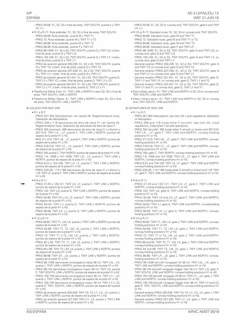
- PRKG 50-58: S1, S2, S3 o final de pista, TWY SOUTH, puerta K y TWYLK, LJ.
• R-13 a R-17: Ruta estándar: S1, S2, S3 o final de pista, TWY SOUTH.- PRKG 60-68: Ruta estándar, puerta M y TWY T1.- PRKG 72: Ruta estándar, puerta M y TWY T1 o T2.- PRKG 80-86: Ruta estándar, puerta M y TWY T2.- PRKG 88-96: Ruta estándar, puerta P y TWY LP.- PRKG 98-154B: S1, S2 o S3, TWY SOUTH, puerta Q y TWY LQ; o bien,final de pista, puerta Q y TWY LQ.
- PRKG 155-159: S1, S2 o S3, TWY SOUTH, puerta Q y TWY LY; o bien,final de pista, puerta Q y TWY LY.
- PRKG de aviación general 200-226: S1, S2 o S3, TWY SOUTH, puertaQ y TWY Y3; o bien, final de pista, puerta Q y TWY Y3.
- PRKG de aviación general 227-230: S1, S2 o S3, TWY SOUTH, puertaQ y TWY LY; o bien, final de pista, puerta Q y TWY LY.
- PRKG de aviación general 231-241: S1, S2 o S3, TWY SOUTH, puerta Q,TWY LY y TWY Y2; o bien, final de pista, puerta Q, TWY LY y Y2.
- PRKG de aviación general 242-247: S1, S2 o S3, TWY SOUTH, puerta Q,TWY LY y Y1; o bien, final de pista, puerta Q, TWY LY y Y1.
• Plataforma Militar Este: S1, TWY LINK y NORTH o bien S2, S3 o final depista, TWY SOUTH, LINK y NORTH.
• Plataforma Militar Oeste: S1, TWY LINK y NORTH o bien S2, S3 o finalde pista, TWY SOUTH, LINK y NORTH.
B) SALIDAS POR RWY 24R
• R-1 a R-7:- PRKG 301-303 (helicópteros): ver casilla 20. Reglamentación local,Operación de helicópteros.
- PRKG 306 y 118 (aeronaves de letra de clave F): ver casilla 20.Reglamentación local, Operación de aeronaves de letra de clave F.
- PRKG 303 (aviones), 306 (aeronaves de letra de clave E o inferior) y307-310: TWY LA,…LF, puerta F, TWY LINK y NORTH, puntos deespera de la pista H1 o H2.
- RKG 311-315: TWY LB,...LF, puerta F, TWY LINK y NORTH, puntos deespera de la pista H1 o H2.
- PRKG 316-318: TWY LC,...LF, puerta F, TWY LINK y NORTH, puntosde espera de la pista H1 o H2.
- PRKG 100: puerta C, TWY NORTH, puntos de espera de la pista H1 o H2.- PRKG 1-6, 100B y 101-103B: TWY LD,...LF, puerta F, TWY LINK yNORTH, puntos de espera de la pista H1 o H2.
- PRKG 8-22 y 104-109: TWY LE, LF, puerta F, TWY LINK y NORTH,puntos de espera de la pista H1 o H2.
- PRKG 23A-26, 114-118B (aeronaves de letra de clave E o inferior) y119: TWY LF, puerta F, TWY LINK y NORTH, puntos de espera de la pistaH1 o H2.
• R-8 a R-11:- PRKG 27-29 y 120-121: TWY LG, LF, puerta F, TWY LINK y NORTH,puntos de espera de la pista H1 o H2.
- PRKG 123: TWY LG, puerta G, TWY LINK y NORTH, puntos de esperade la pista H1 o H2.
- PRKG 30-48: TWY V2 y LG, LF, puerta F, TWY LINK y NORTH, puntosde espera de la pista H1 o H2.
- PRKG 50-54: TWY LJ, puerta G, TWY LINK y NORTH, puntos deespera de la pista H1 o H2.
- PRKG 56-58: TWY LK, LJ, puerta G, TWY LINK y NORTH, puntos deespera de la pista H1 o H2.
• R-13 a R-17:- PRKG 60-62: TWY T1, LM, LK, puerta J, TWY LINK y NORTH, puntos deespera de la pista H1 o H2.
- PRKG 64-68: TWY T1, T2, LM, LK, puerta J, TWY LINK y NORTH,puntos de espera de la pista H1 o H2.
- PRKG 72: TWY T1 o T2, LM, LK, puerta J, TWY LINK y NORTH,puntos de espera de la pista H1 o H2.
- PRKG 80 y 82: TWY T2, T1, LM, LK, puerta J, TWY LINK y NORTH,puntos de espera de la pista H1 o H2.
- PRKG 84 y 86: TWY T2, LM, LK, puerta J, TWY LINK y NORTH, puntosde espera de la pista H1 o H2.
- PRKG 88-96: TWY LP,...LK, puerta J, TWY LINK y NORTH, puntos deespera de la pista H1 o H2.
- PRKG 98-154B (aeronaves envergadura hasta 36 m): TWY LQ,...LK,puerta J, TWY LINK y NORTH, puntos de espera de la pista H1 o H2.
- PRKG 98-154 (aeronaves envergadura mayor 36 m): TWY LQ, puertaP, TWY SOUTH, LINK y NORTH, puntos de espera de la pista H1 o H2.
- PRKG 155-159 (aeronaves envergadura hasta 36 m): TWY LY,...LK,puerta J, TWY LINK y NORTH, puntos de espera de la pista H1 o H2.
- PRKG 155-159 (aeronaves envergadura mayor 36 m): TWY LY y LQ,puerta P, TWY, SOUTH, LINK y NORTH, puntos de espera de la pistaH1 o H2.
- PRKG de aviación general 200-226: TWY Y3, Y2, LY, LQ,..LK, puerta J,TWY LINK y NORTH, puntos de espera de la pista H1 o H2.
- PRKG de aviación general 227-230: TWY LY,..LK, puerta J, TWY LINKy NORTH, puntos de espera de la pista H1 o H2.
- PRKG 50-58: S1, S2, S3 or runway end, TWY SOUTH, gate K and TWYLK, LJ.
• R-13 to R-17: Standard route: S1, S2, S3 or runway end, TWY SOUTH.- PRKG 60-68: Standard route, gate M and TWY T1.- PRKG 72: Standard route, gate M and TWY T1 or T2.- PRKG 80-86: Standard route, gate M and TWY T2.- PRKG 88-96: Standard route, gate P and TWY LP.- PRKG 98-154B: S1, S2 or S3, TWY SOUTH, gate Q and TWY LQ; or,runway end, gate Q and TWY LQ.
- PRKG 155-159: S1, S2 or S3, TWY SOUTH, gate Q and TWY LY; or,runway end, gate Q and TWY LY.
- General aviation PRKG 200-226: S1, S2 or S3, TWY SOUTH, gate Qand TWY Y3; or runway end, gate Q and TWY Y3.
- General aviation PRKG 227-230: S1, S2 or S3, TWY SOUTH, gate Qand TWY LY; or runway end, gate Q and TWY LY.
- General aviation PRKG 231-241: S1, S2 or S3, TWY SOUTH, gate Q,TWY LY and TWY Y2; or runway end, gate Q, TWY LY and Y2.
- General aviation PRKG 242-247: S1, S2 or S3, TWY SOUTH, gate Q,TWY LY and Y1; or runway end, gate Q, TWY LY and Y1.
• East military apron: S1, TWY LINK and NORTH or S2, S3 or runway end,TWY SOUTH, LINK and NORTH.
• West military apron: S1, TWY LINK and NORTH or S2, S3 or runwayend, TWY SOUTH, LINK and NORTH.
B) DEPARTURES BY RWY 24R
• R-1 to R-7:- PRKG 301-303 (helicopters): see item 20, Local regulations, Operationof helicopters.
- PRKG 306 and 118 (code letter F aircraft): see item 20, Localregulations, Code letter F aircraft operations.
- PRKG 303 (aircraft), 306 (code letter E aircraft or lower) and 307-310:TWY LA,…LF, gate F, TWY LINK and NORTH, runway-holdingpositions H1 or H2.
- PRKG 311-315: TWY LB,...LF, gate F, TWY LINK and NORTH, runway-holding positions H1 or H2.
- PRKG 316-318: TWY LC,...LF, gate F, TWY LINK and NORTH, runway-holding positions H1 or H2.
- PRKG 100: gate C, TWY NORTH, runway-holding positions H1 or H2.- PRKG 1-6, 100B and 101-103B: TWY LD,...LF, gate F, TWY LINK andNORTH, runway-holding positions H1 or H2.
- PRKG 8-22 and 104-109: TWY LE, LF, gate F, TWY LINK and NORTH,runway-holding positions H1 or H2.
- PRKG 23A-26, 114-118B (code letter E aircraft or lower) and 119: TWYLF, gate F, TWY LINK and NORTH, runway-holding positions H1 or H2.
• R-8 to R-11:- PRKG 27-29 and 120-121: TWY LG, LF, gate F, TWY LINK andNORTH, runway-holding positions H1 or H2.
- PRKG 123: TWY LG, gate G, TWY LINK and NORTH, runway-holdingpositions H1 or H2.
- PRKG 30-48: TWY V2 and LG, LF, gate F, TWY LINK and NORTH,runway-holding positions H1 or H2.
- PRKG 50-54: TWY LJ, gate G, TWY LINK and NORTH, runwayholdingpositions H1 or H2.
- PRKG 56-58: TWY LK, LJ, gate G, TWY LINK and NORTH, runway-holding positions H1 or H2.
• R-13 to R-17:- PRKG 60-62: TWY T1, LM, LK, gate J, TWY LINK and NORTH, runway-holding positions H1 or H2.
- PRKG 64-68: TWY T1, T2, LM, LK, gate J, TWY LINK and NORTH,runway-holding positions H1 or H2.
- PRKG 72: TWY T1 or T2, LM, LK, gate J, TWY LINK and NORTH,runway-holding positions H1 or H2.
- PRKG 80 and 82: TWY T2, T1, LM, LK, gate J, TWY LINK and NORTH,runway-holding positions H1 or H2.
- PRKG 84 and 86: TWY T2, LM, LK, gate J, TWY LINK and NORTH,runway-holding positions H1 or H2.
- PRKG 88-96: TWY LP,...LK, gate J, TWY LINK and NORTH, runway-holding positions H1 or H2.
- PRKG 98-154B (aircraft wingspan till 36 m): TWY LQ,...LK, gate J,TWY LINK and NORTH, runway-holding positions H1 or H2.
- PRKG 98-154 (aircraft wingspan bigger than 36 m): TWY LQ, gate P,TWY SOUTH, LINK and NORTH, runway-holding positions H1 or H2.
- PRKG 155-159 (aircraft wingspan till 36 m): TWY LY,...LK, gate J, TWYLINK and NORTH, runway-holding positions H1 or H2.
- PRKG 155-159 (aircraft wingspan bigger than 36 m): TWY LY and LQ,gate P, TWY, SOUTH, LINK and NORTH, runway-holding positions H1or H2.
- General aviation PRKG 200-226: TWY Y3, Y2, LY, LQ,..LK, gate J, TWYLINK and NORTH, runway-holding positions H1 or H2.
- General aviation PRKG 227-230: TWY LY,..LK, gate J, TWY LINK andNORTH, runway-holding positions H1 or H2.
AIS-ESPAÑA AIRAC AMDT 05/18
AD 2-LEPA/LESJ 14 AIPWEF 21-JUN-18 ESPAÑA
- PRKG de aviación general 231-241: TWY Y2, LY,..LK, puerta J, TWYLINK y NORTH, puntos de espera de la pista H1 o H2.
- PRKG de aviación general 242-247: TWY Y1, LY,...LK, puerta J, TWYLINK y NORTH, puntos de espera de la pista H1 o H2.
• Plataforma Militar Este: TWY NORTH, puntos de espera de la pista H1 oH2.
• Plataforma Militar Oeste: TWY NORTH, puntos de espera de la pista H1o H2.
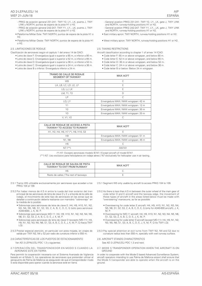
2.5. LIMITACIONES DE RODAJE
Clasificación de aeronaves según el capítulo 1 del anexo 14 de OACI:• Letra de clave F: Envergadura igual o superior a 65 m, e inferior a 80 m.• Letra de clave E: Envergadura igual o superior a 52 m, e inferior a 65 m.• Letra de clave D: Envergadura igual o superior a 36 m, e inferior a 52 m.• Letra de clave C: Envergadura igual o superior a 24 m, e inferior a 36 m.• Letra de clave B o inferior: Envergadura inferior a 24 m.
2.5.1 Tramo W5 utilizable exclusivamente por aeronaves que accedan a losPRKG 104 al 109.
2.5.2 Por haber menos de 4.5 m entre la rueda del tren exterior del trenprincipal de las aeronaves de letra de clave D y E y el borde de la calle derodaje, el movimiento de este tipo de aeronaves en las zonas que sedetallan a continuación debería realizarse con maniobra “sobreviraje” enla medida de lo posible:• Sobreviraje para aeronaves de letra de clave E: H4, H9, H10, N1, N2,
N3, N4, N5, N6, S1, S2, S3, Z, A, B, C, D, E, G (sólo para aeronaveA340-600), J, K, M, P.
• Sobreviraje para aeronaves MD-11: H4, H9, H10, N1, N2, N3, N4, N5,N6, S1, S2, S3, Z, A, B, C, D, E, J, K, M, P.
• Sobreviraje para aeronaves de letra de clave D (excepto MD-11): H4,H9, N1, N2, N3, N5, N6, S1, S3, A, B, C, D, E, J, K, M, P, Q (hacia TWYLQ).
2.5.3 Prestar especial atención, en particular con pista mojada, en virajes desalida por TWY N2, N4 y S2 por radio de curvatura inferior a 550 m.
2.6 CARACTERÍSTICAS DE LOS PUESTOS DE ESTACIONAMIENTO
Ver AD 2-LEPA/LESJ PDC 1.3 y siguientes.
2.7 OPERACIÓN DEL TRANSPONDEDOR EN MODO S CUANDO LAAERONAVE ESTÉ EN TIERRA
Para permitir la cooperación necesaria con el Sistema Avanzado de Vigilanciabasado en el Modo S, los operadores de aeronaves que pretendan utilizar elaeropuerto de Palma de Mallorca se asegurarán de que el transpondedor modoS está disponible para operar cuando la aeronave esté en tierra.
- General aviation PRKG 231-241: TWY Y2, LY,..LK, gate J, TWY LINKand NORTH, runway-holding positions H1 or H2.
- General aviation PRKG 242-247: TWY Y1, LY,...LK, gate J, TWY LINKand NORTH, runway-holding positions H1 or H2.
• East military apron: TWY NORTH, runway-holding positions H1 or H2.
• West military apron: TWY NORTH, runway-holding positions H1 or H2.
2.5. TAXIING RESTRICTIONS
Aircraft classification according to chapter 1 of annex 14 ICAO:• Code letter F: 65 m or above wingspan, and below 80 m.• Code letter E: 52 m or above wingspan, and below 65 m.• Code letter D: 36 m or above wingspan, and below 52 m.• Code letter C: 24 m or above wingspan, and below 36 m.• Code letter B or below: Below 24 m wingspan.
2.5.1 Segment W5 only usable by aircraft to access PRKG 104 to 109.
2.5.2 As there is less than 4.5 m between the outer wheel of the main gear ofcode letter D and E aircraft and the taxiway edge, the movement ofthese types of aircraft in the areas listed below must be made with"oversteering" manoeuvre, as far as possible:
• Oversteering for code letter E aircraft: H4, H9, H10, N1, N2, N3, N4,N5, N6, S1, S2, S3, Z, A, B, C, D, E, G (only for A340-600 aircraft), J, K,M, P.
• Oversteering for MD-11 aircraft: H4, H9, H10, N1, N2, N3, N4, N5, N6,S1, S2, S3, Z, A, B, C, D, E, J, K, M, P.
• Oversteering for code letter D aircraft (except MD-11): H4, H9, N1, N2,N3, N5, N6, S1, S3, A, B, C, D, E, J, K, M, P, Q (to TWY LQ).
2.5.3 Pay special attention at exit turns from TWY N2, N4 and S2 due tocurvature radius less than 550 m, specially with wet runway surface.
2.6. AIRCRAFT STANDS CHARACTERISTICS
See AD 2-LEPA/LESJ PDC 1.3 and next.
2.7. MODE S TRANSPONDER OPERATION WHEN THE AIRCRAFT IS ONGROUND
In order to cooperate with the Mode-S based Advanced Surveillance System,aircraft operators intending to use Palma de Mallorca airport shall ensure thatthe Mode S transponder are able to operate when the aircraft is on theground.
AIRAC AMDT 05/18 AIS-ESPAÑA
CALLE DE RODAJE DE SALIDA DE PISTATAXIWAY TO EXIT FROM RUNWAY
MAX ACFT
H5 C
Resto de calles / The rest of taxiways E
CALLE DE RODAJE DE ACCESO A PISTATAXIWAY TO ACCESS TO RUNWAY
MAX ACFT
H1, H2, H4, H6, H7 (*), H8, H10, S3 E
H9 Envergadura MAX / MAX wingspan: 51 m
N1, N6 Envergadura MAX / MAX wingspan: 45 m
H5 C
N7 (**) AW101
(*) H7: Excepto aeronaves modelo B747 / Except aircraft of model B747.(**) N7: Uso exclusivo para helicópteros en rodaje aéreo / N7 exclusively for helicopter use in air taxiing.
TRAMO DE CALLE DE RODAJESEGMENT OF TAXIWAY
MAX ACFT
W5 C
LA, LB, LC, LD, LE, LF E
LG, LJ, LK E
LM, T1, T2 D
LP C
LQ, LY Envergadura MAX / MAX wingspan: 42 m
Y1 Envergadura MAX / MAX wingspan: 12 m
Y2 Envergadura MAX / MAX wingspan: 30 m
Y3 Envergadura MAX / MAX wingspan: 20 m
V, V1, V2 C
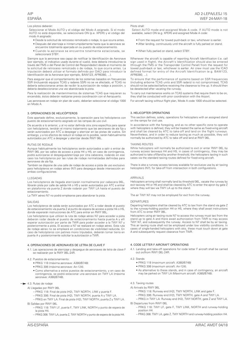
AIP AD 2-LEPA/LESJ 15ESPAÑA WEF 24-MAY-18
Los pilotos deberán:Seleccionar el Modo AUTO y el código del Modo A asignado. Si el modoAUTO no está disponible, se seleccionará ON (p.e. XPDR) y el código delmodo A asignado:
• Desde la solicitud de retroceso remolcado o rodaje, lo que ocurra antes.• Después del aterrizaje e ininterrumpidamente hasta que la aeronave se
encuentre totalmente aparcada en su puesto de estacionamiento.• Cuando la aeronave se encuentre totalmente estacionada, se
seleccionará STBY.
Siempre que la aeronave sea capaz de notificar la Identificación de Aeronave(por ejemplo, el indicativo usado durante el vuelo), ésta debería introducirse (através del FMS o del Panel de Control del Respondedor) desde el momento dela solicitud de retroceso remolcado o de rodaje, lo que ocurra antes. Latripulación deberá utilizar el formato definido por OACI para introducir laIdentificación de la Aeronave (por ejemplo, BAW123, AFR6380, ...).
Para asegurar que el comportamiento de los sistemas basados en frecuenciasSSR (incluyendo equipos TCAS y radares SSR) no se ve afectado, el TCAS nodebería seleccionarse antes de recibir la autorización de rodaje a posición, ydebería deseleccionarse una vez abandonada la pista.
Para la realización de mantenimientos de sistemas TCAS que requieran suencendido, éstos deberán realizarse previa coordinación con el Aeropuerto.
Las aeronaves en rodaje sin plan de vuelo, deberían seleccionar el código 1000en Modo A.
3. OPERACIONES DE HELICÓPTEROS
Este apartado define, exclusivamente, la operación para los helicópteros conpuesto de estacionamiento asignado en las rampas de uso civil.
De acuerdo a lo anterior, y al no estar definida otra zona específica para operarcon helicópteros, tendrán el mismo tratamiento que las aeronaves de ala fija yserán autorizados por ATC a despegar y aterrizar en las pistas de vuelos. Sinembargo, y a los efectos de reducir el rodaje en lo posible, serán habitualmenteautorizados por ATC a despegar y aterrizar desde RWY 06L.
RUTAS DE RODAJEAunque habitualmente los helicópteros serán autorizados a salir o entrar deRWY 06L por las calles de acceso a pista H4 y H5; en caso de contingencia,podrá autorizarse el despegue/aterrizaje por otra cabecera, rodando en esecaso los helicópteros por las rutas de rodaje normalizadas definidas paraaeronaves de ala fija.También se dispone de una calle de rodaje de acceso a pista de uso exclusivopara helicópteros en rodaje aéreo (N7) para despegue desde intersección enambas configuraciones.
LLEGADASLos helicópteros de llegada aterrizarán normalmente por cabecera 06L,librarán pista por calle de salida H4 o H5 y serán autorizados por ATC a entraren plataforma vía puerta Z donde rodarán por TWY LA hasta el puesto deestacionamiento.La TWY aéreo N7 no podrá emplearse para abandonar la pista.
SALIDASLos helicópteros de salida serán autorizados por ATC a rodar desde el puestode estacionamiento vía puerta Z al punto de espera de acceso a pista H4 o H5,donde esperarán instrucciones de ATC para entrar en RWY 06L.Los helicópteros que utilicen la ruta de rodaje aéreo N7 para acceder a pistadeberán rodar desde el puesto de estacionamiento hasta puerta A y allíesperar autorización por parte de TWR para poder acceder a la TWY N7 yposteriormente a pista. El acceso a N7 se realizará en rodaje aéreo. Esta rutade rodaje aéreo no se empleará en condiciones de visibilidad reducida. Encaso de helicópteros con patines mono tripulados, deberán tomar tierra enpuerta A y posteriormente solicitar la autorización a TWR.
4. OPERACIONES DE AERONAVES DE LETRA DE CLAVE F
4.1. Las operaciones de aterrizaje y despegue de aeronaves de letra de clave Fse realizarán por la RWY 06L-24R.
4.2. Puestos de estacionamiento:• PRKG 118 (máxima aeronave: A380/B748)• PRKG 306 (máxima aeronave: An-124).• Como alternativa a estos puestos de estacionamiento, y en caso de
contingencia, se podrá estacionar una aeronave en TWY LA (máximaaeronave: A380/B748).
4.3. Rutas de rodaje
A) Llegadas por RWY 06L– PRKG 118: Final de pista (H2), TWY NORTH, LINK y puerta F.– PRKG 306: Final de pista (H2), TWY NORTH, puerta A y TWY LA.– PRKG en TWY LA: Final de pista (H2), TWY NORTH, puerta Z y TWY LA.
B) Salidas por RWY 06L– PRKG 118: TWY LF, puerta F, TWY LINK, NORTH y punto de espera de
la pista H4.– PRKG 306: TWY LA, puerta Z, TWY NORTH y punto de espera de la pista H4.
Pilots shall:Select AUTO mode and assigned Mode A code. If AUTO mode is notavailable, select ON (e.g. XPDR) and assigned Mode A code:
• From the request for towed push-back or taxi, whichever is earlier.• After landing, continuously until the aircraft is fully parked on stand.
• When fully parked on stand, select STBY.
Whenever the aircraft is capable of reporting Aircraft Identification (i.e. callsign used in flight), the Aircraft's Identification should also be entered(through the FMS or the Transponder Control Panel) from the request fortowed push-back or taxi, whichever is earlier. Air crew must use the ICAOdefined format for entry of the Aircraft Identification (e.g. BAW123,AFR6380, ...).
To ensure that the performance of systems based on SSR frequencies(including airborne TCAS units and SSR radars) is not compromised, TCASshould not be selected before receiving the clearance to line up. It should thenbe deselected after vacating the runway.
To carry out maintenance works on TCAS systems that require them to be on,they shall be conducted with prior coordination with the Airport.
For aircraft taxiing without flight plan, Mode A code 1000 should be selected.
3. HELICOPTER OPERATIONS
This section defines, solely, operations for helicopters with an assigned standon the ramps for civil use.
In accordance with the foregoing, and as no other specific zone to operatewith helicopters is defined, they will be treated the same as fixed-wing aircraftand shall be cleared by ATC to take-off and land on the flight runways.Nevertheless, and in order to reduce taxiing as much as possible, they willnormally be authorized by ATC to take off and land at RWY 06L.
TAXIING ROUTESWhile helicopters will normally be authorized to exit or enter RWY 06L byrunway access taxiways H4 and H5, in cases of contingency, they may beauthorized to take off/land by another threshold, the helicopters taxiing in suchcases via the standard taxiing routes defined for fixed-wing aircraft.
There is also a runway access taxiway available for exclusive use by air taxiinghelicopters (N7), for take-off from intersection in both configurations.
ARRIVALSHelicopters arriving shall normally land by threshold 06L, vacate the runway byexit taxiway H4 or H5 and shall be cleared by ATC to enter the apron by gate Zwhere they will taxi via TWY LA up to the stand.
The air TWY N7 may not be employed for exit from the runway.
DEPARTURESDeparting helicopters shall be cleared by ATC to taxi from the stand via gate Zto the runway-holding position H4 or H5, where they shall await instructionsfrom ATC to enter RWY 06L.Helicopters using air taxiing route N7 to access the runway must taxi from thestand up to gate A and there await authorization from TWR to may accessTWY N7, and subsequently the runway. Access to N7 shall be by air taxiing.This air taxiing route shall not be employed under low visibility conditions. Incases of single-handed helicopters with skis, these must touch down at gateA and subsequently request clearance from TWR.
4. CODE LETTER F AIRCRAFT OPERATIONS
4.1. Landing and take-off operations for code letter F aircraft shall be carriedout on/from RWY 06L-24R.
4.2. Stands• PRKG 118 (maximum aircraft: A380/B748)• PRKG 306 (maximum aircraft: An-124).• As alternative to these stands, and in case of contingency, an aircraft
may be parked on TWY LA (Maximum aircraft: A380/B748).
4.3. Taxiing routes
A) Arrivals by RWY 06L– PRKG 118: Runway end (H2), TWY NORTH, LINK and gate F.– PRKG 306: Runway end (H2), TWY NORTH, gate A and TWY LA.– PRKG in TWY LA: Runway end (H2), TWY NORTH, gate Z and TWY LA.
B) Departures from RWY 06L– PRKG 118: TWY LF, gate F, TWY LINK, NORTH and runway-holding
position H4.– PRKG 306: TWY LA, gate Z, TWY NORTH and runway-holding position H4.
AIS-ESPAÑA AIRAC AMDT 04/18
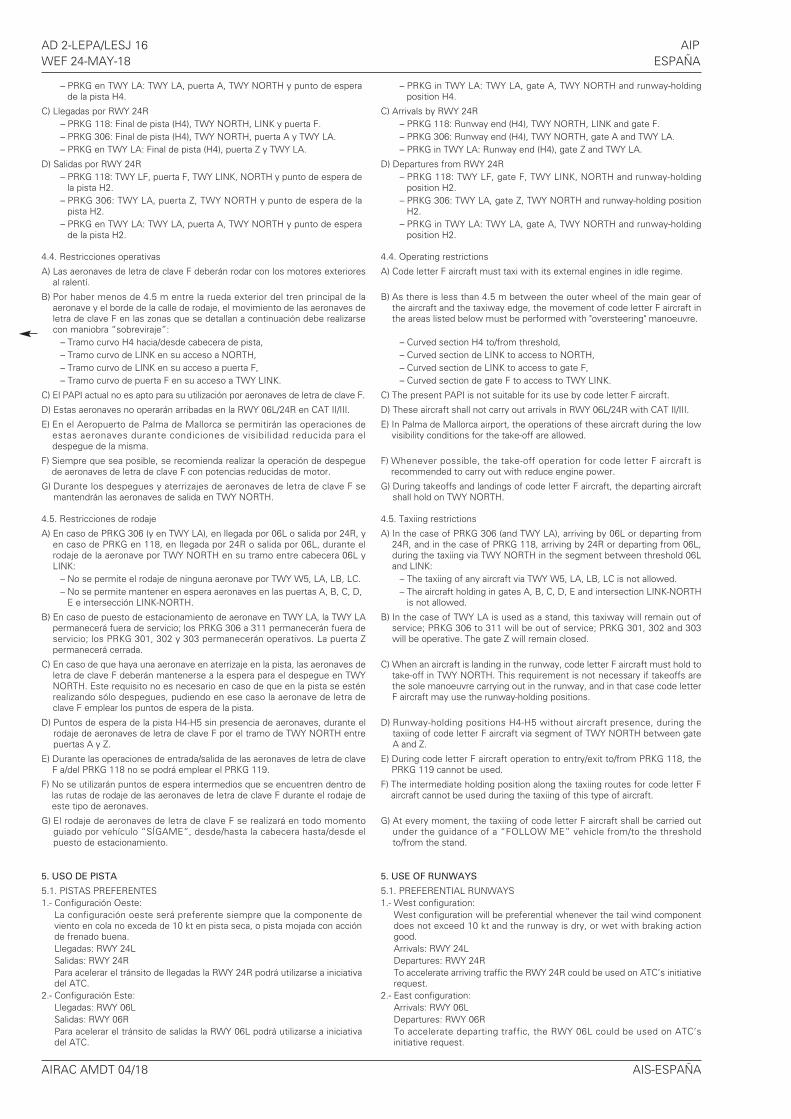
AD 2-LEPA/LESJ 16 AIPWEF 24-MAY-18 ESPAÑA
– PRKG en TWY LA: TWY LA, puerta A, TWY NORTH y punto de esperade la pista H4.
C) Llegadas por RWY 24R– PRKG 118: Final de pista (H4), TWY NORTH, LINK y puerta F.– PRKG 306: Final de pista (H4), TWY NORTH, puerta A y TWY LA.– PRKG en TWY LA: Final de pista (H4), puerta Z y TWY LA.
D) Salidas por RWY 24R– PRKG 118: TWY LF, puerta F, TWY LINK, NORTH y punto de espera de
la pista H2.– PRKG 306: TWY LA, puerta Z, TWY NORTH y punto de espera de la
pista H2.– PRKG en TWY LA: TWY LA, puerta A, TWY NORTH y punto de espera
de la pista H2.
4.4. Restricciones operativas
A) Las aeronaves de letra de clave F deberán rodar con los motores exterioresal ralentí.
B) Por haber menos de 4.5 m entre la rueda exterior del tren principal de laaeronave y el borde de la calle de rodaje, el movimiento de las aeronaves deletra de clave F en las zonas que se detallan a continuación debe realizarsecon maniobra “sobreviraje”:
– Tramo curvo H4 hacia/desde cabecera de pista,– Tramo curvo de LINK en su acceso a NORTH,– Tramo curvo de LINK en su acceso a puerta F,– Tramo curvo de puerta F en su acceso a TWY LINK.
C) El PAPI actual no es apto para su utilización por aeronaves de letra de clave F.
D) Estas aeronaves no operarán arribadas en la RWY 06L/24R en CAT II/III.
E) En el Aeropuerto de Palma de Mallorca se permitirán las operaciones deestas aeronaves durante condiciones de visibilidad reducida para eldespegue de la misma.
F) Siempre que sea posible, se recomienda realizar la operación de despeguede aeronaves de letra de clave F con potencias reducidas de motor.
G) Durante los despegues y aterrizajes de aeronaves de letra de clave F semantendrán las aeronaves de salida en TWY NORTH.
4.5. Restricciones de rodaje
A) En caso de PRKG 306 (y en TWY LA), en llegada por 06L o salida por 24R, yen caso de PRKG en 118, en llegada por 24R o salida por 06L, durante elrodaje de la aeronave por TWY NORTH en su tramo entre cabecera 06L yLINK:
– No se permite el rodaje de ninguna aeronave por TWY W5, LA, LB, LC.– No se permite mantener en espera aeronaves en las puertas A, B, C, D,
E e intersección LINK-NORTH.
B) En caso de puesto de estacionamiento de aeronave en TWY LA, la TWY LApermanecerá fuera de servicio; los PRKG 306 a 311 permanecerán fuera deservicio; los PRKG 301, 302 y 303 permanecerán operativos. La puerta Zpermanecerá cerrada.
C) En caso de que haya una aeronave en aterrizaje en la pista, las aeronaves deletra de clave F deberán mantenerse a la espera para el despegue en TWYNORTH. Este requisito no es necesario en caso de que en la pista se esténrealizando sólo despegues, pudiendo en ese caso la aeronave de letra declave F emplear los puntos de espera de la pista.
D) Puntos de espera de la pista H4-H5 sin presencia de aeronaves, durante elrodaje de aeronaves de letra de clave F por el tramo de TWY NORTH entrepuertas A y Z.
E) Durante las operaciones de entrada/salida de las aeronaves de letra de claveF a/del PRKG 118 no se podrá emplear el PRKG 119.
F) No se utilizarán puntos de espera intermedios que se encuentren dentro delas rutas de rodaje de las aeronaves de letra de clave F durante el rodaje deeste tipo de aeronaves.
G) El rodaje de aeronaves de letra de clave F se realizará en todo momentoguiado por vehículo “SÍGAME”, desde/hasta la cabecera hasta/desde elpuesto de estacionamiento.
5. USO DE PISTA
5.1. PISTAS PREFERENTES1.- Configuración Oeste:
La configuración oeste será preferente siempre que la componente deviento en cola no exceda de 10 kt en pista seca, o pista mojada con acciónde frenado buena.Llegadas: RWY 24LSalidas: RWY 24RPara acelerar el tránsito de llegadas la RWY 24R podrá utilizarse a iniciativadel ATC.
2.- Configuración Este:Llegadas: RWY 06LSalidas: RWY 06RPara acelerar el tránsito de salidas la RWY 06L podrá utilizarse a iniciativadel ATC.
– PRKG in TWY LA: TWY LA, gate A, TWY NORTH and runway-holdingposition H4.
C) Arrivals by RWY 24R– PRKG 118: Runway end (H4), TWY NORTH, LINK and gate F.– PRKG 306: Runway end (H4), TWY NORTH, gate A and TWY LA.– PRKG in TWY LA: Runway end (H4), gate Z and TWY LA.
D) Departures from RWY 24R– PRKG 118: TWY LF, gate F, TWY LINK, NORTH and runway-holding
position H2.– PRKG 306: TWY LA, gate Z, TWY NORTH and runway-holding position
H2.– PRKG in TWY LA: TWY LA, gate A, TWY NORTH and runway-holding
position H2.
4.4. Operating restrictions
A) Code letter F aircraft must taxi with its external engines in idle regime.
B) As there is less than 4.5 m between the outer wheel of the main gear ofthe aircraft and the taxiway edge, the movement of code letter F aircraft inthe areas listed below must be performed with "oversteering" manoeuvre.
– Curved section H4 to/from threshold,– Curved section de LINK to access to NORTH,– Curved section de LINK to access to gate F,– Curved section de gate F to access to TWY LINK.
C) The present PAPI is not suitable for its use by code letter F aircraft.
D) These aircraft shall not carry out arrivals in RWY 06L/24R with CAT II/III.
E) In Palma de Mallorca airport, the operations of these aircraft during the lowvisibility conditions for the take-off are allowed.
F) Whenever possible, the take-off operation for code letter F aircraft isrecommended to carry out with reduce engine power.
G) During takeoffs and landings of code letter F aircraft, the departing aircraftshall hold on TWY NORTH.
4.5. Taxiing restrictions
A) In the case of PRKG 306 (and TWY LA), arriving by 06L or departing from24R, and in the case of PRKG 118, arriving by 24R or departing from 06L,during the taxiing via TWY NORTH in the segment between threshold 06Land LINK:
– The taxiing of any aircraft via TWY W5, LA, LB, LC is not allowed.– The aircraft holding in gates A, B, C, D, E and intersection LINK-NORTH
is not allowed.
B) In the case of TWY LA is used as a stand, this taxiway will remain out ofservice; PRKG 306 to 311 will be out of service; PRKG 301, 302 and 303will be operative. The gate Z will remain closed.
C) When an aircraft is landing in the runway, code letter F aircraft must hold totake-off in TWY NORTH. This requirement is not necessary if takeoffs arethe sole manoeuvre carrying out in the runway, and in that case code letterF aircraft may use the runway-holding positions.
D) Runway-holding positions H4-H5 without aircraft presence, during thetaxiing of code letter F aircraft via segment of TWY NORTH between gateA and Z.
E) During code letter F aircraft operation to entry/exit to/from PRKG 118, thePRKG 119 cannot be used.
F) The intermediate holding position along the taxiing routes for code letter Faircraft cannot be used during the taxiing of this type of aircraft.
G) At every moment, the taxiing of code letter F aircraft shall be carried outunder the guidance of a “FOLLOW ME” vehicle from/to the thresholdto/from the stand.
5. USE OF RUNWAYS
5.1. PREFERENTIAL RUNWAYS1.- West configuration:
West configuration will be preferential whenever the tail wind componentdoes not exceed 10 kt and the runway is dry, or wet with braking actiongood.Arrivals: RWY 24LDepartures: RWY 24RTo accelerate arriving traffic the RWY 24R could be used on ATC’s initiativerequest.
2.- East configuration:Arrivals: RWY 06LDepartures: RWY 06RTo accelerate departing traffic, the RWY 06L could be used on ATC’sinitiative request.
AIRAC AMDT 04/18 AIS-ESPAÑA
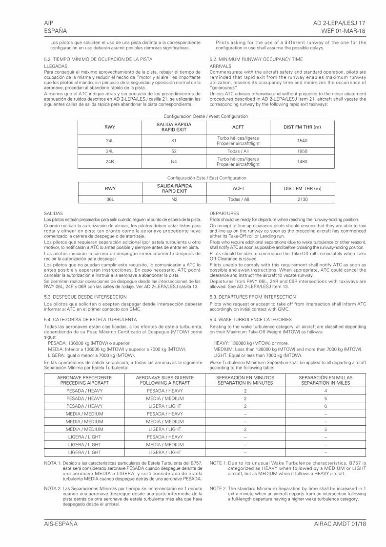
AIP AD 2-LEPA/LESJ 17ESPAÑA WEF 01-MAR-18
Los pilotos que soliciten el uso de una pista distinta a la correspondienteconfiguración en uso deberán asumir posibles demoras significativas.
5.2. TIEMPO MÍNIMO DE OCUPACIÓN DE LA PISTA
LLEGADASPara conseguir el máximo aprovechamiento de la pista, rebajar el tiempo deocupación de la misma y reducir el hecho de “motor y al aire” es importanteque los pilotos al mando, sin perjuicio de la seguridad y operación normal de laaeronave, procedan al abandono rápido de la pista.A menos que el ATC indique otras y sin perjuicio de los procedimientos deatenuación de ruidos descritos en AD 2-LEPA/LESJ casilla 21, se utilizarán lassiguientes calles de salida rápida para abandonar la pista correspondiente.
SALIDASLos pilotos estarán preparados para salir cuando lleguen al punto de espera de la pista.Cuando reciban la autorización de alinear, los pilotos deben estar listos pararodar y alinear en pista tan pronto como la aeronave precedente hayacomenzado la carrera de despegue o de aterrizaje.Los pilotos que requieran separación adicional (por estela turbulenta u otromotivo), lo notificarán a ATC lo antes posible y siempre antes de entrar en pista.Los pilotos iniciarán la carrera de despegue inmediatamente después derecibir la autorización para despegar.Los pilotos que no puedan cumplir este requisito, lo comunicarán a ATC loantes posible y esperarán instrucciones. En caso necesario, ATC podrácancelar la autorización e instruir a la aeronave a abandonar la pista.Se permiten realizar operaciones de despegue desde las intersecciones de lasRWY 06L, 24R y 06R con las calles de rodaje. Ver AD 2-LEPA/LESJ casilla 13.
5.3. DESPEGUE DESDE INTERSECCION
Los pilotos que soliciten o acepten despegar desde intersección deberáninformar al ATC en el primer contacto con GMC.
5.4. CATEGORÍAS DE ESTELA TURBULENTA
Todas las aeronaves están clasificadas, a los efectos de estela turbulenta,dependiendo de su Peso Máximo Certificado al Despegue (MTOW) comosigue:
PESADA: 136000 kg (MTOW) o superior.MEDIA: Inferior a 136000 kg (MTOW) y superior a 7000 kg (MTOW).LIGERA: Igual o menor a 7000 kg (MTOW).
En las operaciones de salida se aplicará, a todas las aeronaves la siguienteSeparación Mínima por Estela Turbulenta:
NOTA 1: Debido a las características particulares de Estela Turbulenta del B757,éste será considerado aeronave PESADA cuando despegue delante deuna aeronave MEDIA o LIGERA, y será considerada de estelaturbulenta MEDIA cuando despegue detrás de una aeronave PESADA.
NOTA 2: Las Separaciones Mínimas por tiempo se incrementarán en 1 minutocuando una aeronave despegue desde una parte intermedia de lapista detrás de otra aeronave de estela turbulenta más alta que hayadespegado desde el umbral.
Pilots asking for the use of a different runway of the one for theconfiguration in use shall assume the possible delays.
5.2. MINIMUM RUNWAY OCCUPANCY TIME
ARRIVALSCommensurate with the aircraft safety and standard operation, pilots arereminded that rapid exit from the runway enables maximum runwayutilization, lessens its occupancy time and minimizes the occurrence of “go-arounds”.Unless ATC advises otherwise and without prejudice to the noise abatementprocedures described in AD 2-LEPA/LESJ item 21, aircraft shall vacate thecorresponding runway by the following rapid exit taxiways:
DEPARTURESPilots should be ready for departure when reaching the runway-holding position.On receipt of line-up clearance pilots should ensure that they are able to taxiand line-up on the runway as soon as the preceding aircraft has commencedeither its Take-Off roll or Landing run. Pilots who require additional separations (due to wake turbulence or other reason),shall notify ATC as soon as possible and before crossing the runway-holding position.Pilots should be able to commence the Take-Off roll immediately when TakeOff Clearance is issued. Pilots unable to comply with this requirement shall notify ATC as soon aspossible and await instructions. When appropriate, ATC could cancel theclearance and instruct the aircraft to vacate runway.Departures from RWY 06L, 24R and 06R intersections with taxiways areallowed. See AD 2-LEPA/LESJ item 13.
5.3. DEPARTURES FROM INTERSECTION
Pilots who request or accept to take off from intersection shall inform ATCaccordingly on initial contact with GMC.
5.4. WAKE TURBULENCE CATEGORIES
Relating to the wake turbulence category, all aircraft are classified dependingon their Maximum Take-Off Weight (MTOW) as follows:
HEAVY: 136000 kg (MTOW) or more.MEDIUM: Less than 136000 kg (MTOW) and more than 7000 kg (MTOW).LIGHT: Equal or less than 7000 kg (MTOW).
Wake Turbulence Minimum Separation shall be applied to all departing aircraftaccording to the following table:
NOTE 1: Due to its unusual Wake Turbulence characteristics, B757 iscategorized as HEAVY when followed by a MEDIUM or LIGHTaircraft, but as MEDIUM when it follows a HEAVY aircraft.
NOTE 2: The standard Minimum Separation by time shall be increased in 1extra minute when an aircraft departs from an intersection followinga full-length departure having a higher wake turbulence category.
AIS-ESPAÑA AIRAC AMDT 01/18
Configuración Este / East Configuration
Configuración Oeste / West Configuration
RWYSALIDA RÁPIDA
RAPID EXITACFT DIST FM THR (m)
24L S1 Turbo hélices/ligerasPropeller aircraft/light 1540
24L S2 Todas / All 1950
24R N4 Turbo hélices/ligerasPropeller aircraft/light 1480
RWYSALIDA RÁPIDA
RAPID EXITACFT DIST FM THR (m)
06L N2 Todas / All 2130
AERONAVE PRECEDENTEPRECEDING AIRCRAFT
AERONAVE SUBSIGUIENTEFOLLOWING AIRCRAFT
SEPARACIÓN EN MINUTOSSEPARATION IN MINUTES
SEPARACIÓN EN MILLASSEPARATION IN MILES
PESADA / HEAVY PESADA / HEAVY 2 4
PESADA / HEAVY MEDIA / MEDIUM 2 5
PESADA / HEAVY LIGERA / LIGHT 2 6
MEDIA / MEDIUM PESADA / HEAVY – –
MEDIA / MEDIUM MEDIA / MEDIUM – –
MEDIA / MEDIUM LIGERA / LIGHT 2 5
LIGERA / LIGHT PESADA / HEAVY – –
LIGERA / LIGHT MEDIA / MEDIUM – –
LIGERA / LIGHT LIGERA / LIGHT – –
AD 2-LEPA/LESJ 18 AIPWEF 01-MAR-18 ESPAÑA
NOTA 3: Las Separaciones Mínimas por distancia se aplicarán de manera que,una vez en el aire, las aeronaves implicadas cumplan con laSeparación Mínima especificada.
Cuando una aeronave no pueda aceptar la separación mínima por estelaturbulenta informará de ello a ATC lo antes posible al comunicar en lafrecuencia DEP y antes de recibir la autorización para alinearse. Una vezrecibida la autorización para alinearse en pista, los pilotos que no hayancomunicado la necesidad de una mayor separación por estela turbulenta seentenderá que aceptan las Separaciones Mínimas por Estela Turbulenta.
6. NOTIFICACIONES DE SEGURIDAD OPERACIONAL
Los pilotos/compañía deberán comunicar lo antes posible al aeropuerto elaccidente, incidente y suceso o evento que pueda tener alguna potencialafección a la seguridad operacional en el que se haya visto involucrado o seatestigo del mismo.
El objeto de estas notificaciones es la recopilación de la información para lamejora de la seguridad operacional, independientemente de la notificaciónobligatoria de sucesos ante la autoridad aeronáutica pertinente. Los datos sepodrán enviar en cualquier formato incluyendo al menos la siguienteinformación:
• Fecha y hora.• Lugar.• Implicados (datos para identificar los vehículos, aeronaves... implicados).• Empresas involucradas.• Descripción de los hechos.• Cualquier otro dato que se considere relevante (ej: condiciones de
iluminación, meteorológicas, fase de la operación como despegue /aterrizaje / escala, estado del pavimento…).
La dirección de correo electrónico del aeropuerto, para la recepción de lasnotificaciones de seguridad operacional, es la siguiente:
Además de notificar al aeropuerto mediante el sistema indicado, es necesarioenviar al menos los datos básicos del accidente, incidente, suceso o evento alproveedor de servicios de control de tránsito aéreo (ATC).
En el caso específico de notificaciones de seguridad relacionadas con elproveedor de servicios de control de tránsito aéreo (área de maniobras, fasesde vuelo y espacio aéreo ATS) pueden remitirse a la dirección de correoelectrónico:
7. PROCEDIMIENTOS A-CDM
7.1. DEFINICIONES• A-CDM: Airport Collaborative Decision Making
• TOBT: Hora objetivo de fuera de calzos. Hora que la compañía aérea oagente de asistencia en tierra espera estar listo, con puertas cerradas,pasarela desconectada y equipo para retroceso de aeronaveconectado.
• TSAT: Hora objetivo de autorización de puesta en marcha. Hora calculadade puesta en marcha en función de la TOBT, el tiempo de rodaje desdeel puesto de estacionamiento, la CTOT (en caso de estar sujeto aregulación) y la capacidad operacional del aeropuerto.
• SOBT: Hora programada de fuera de calzos.
7.2. GENERAL
En el Aeropuerto de Palma de Mallorca se aplican procesos A-CDM en lasecuencia de salida de aeronaves. Los procesos A-CDM empiezan tres horasantes de la hora estimada de fuera de calzos (EOBT) y finalizan con el despeguede la aeronave. Durante todo el proceso deberá mantenerse actualizada lainformación relativa al vuelo. La información será enviada de forma automáticaal Network Manager Operations Centre (NMOC) de Eurocontrol y será usadapara una mejor gestión en la asignación de horas calculadas de despegue(CTOT).
En el Aeropuerto de Palma de Mallorca se aplica el sistema FAM (FlightActivation Monitoring) gestionado por Eurocontrol. Para evitar que los planesde vuelo sean suspendidos automáticamente, se deberá mantener actualizadala EOBT y TOBT hasta la solicitud de puesta en marcha y ceñirse a la TSAT, demodo que el flujo de tráfico permita que se produzca la salida lo más cercaposible a la TTOT.
7.3. PROCESO
7.3.1. VALIDACIÓN DEL SLOT AEROPORTUARIO Y PLAN DE VUELO
Tres horas antes de la EOBT se validará en el sistema A-CDM la informacióndel plan de vuelo (FPL) presentada respecto al slot aeroportuario, debiendocoincidir en ambos la SOBT con la EOBT del FPL inicialmente presentado, eldestino del vuelo y el tipo de aeronave. Si la información no concuerda, elsistema generará una alarma y un mensaje automático a la compañía y a suagente de asistencia en tierra, quienes deberán actualizar la información.
7.3.2. IMPUTACIÓN DE TOBT
Tan pronto la compañía aérea o su agente de asistencia en tierra dispongan deinformación de la hora objetivo de fuera de calzos, imputarán la TOBT en el
NOTE 3: The standard Minimum Separation by distance shall be applied in away that, once airborne, aircraft shall comply with their specifiedMinimum Separation.
Aircraft unable to accept the minimum wake turbulence separation shalladvise ATC as soon as possible on transfer to DEP frequency but before line-up clearance is issued. Pilots accepting line-up clearance withoutdeclaring the need for additional wake turbulence separation shall be assumedto have accepted the standard Wake Turbulence MinimumSeparation.
6. OPERATIONAL SAFETY REPORTS
Pilots/operator shall report to the airport as soon as possible about anyaccidents, incidents, occurrences or events which may have a potentialoperational impact and in which they have been involved or witnessed.
The aim of these reports is the compilation of the information in order toimprove operational safety, independently of the compulsory report of theoccurrence to the appropriate aeronautical authority. Data may be sent in anyformat, including at least the following information:
• Date and time.• Site.• Parties involved (data used to identify vehicles, aircraft...involved).• Companies implicated.• Description of the facts.• Any other data considered relevant (e.g. lighting conditions, weather,
phase of the operation such as take-off / landing / stopover, pavementconditions…).
Contact e-mail address of the airport, for the reception of operational safetyreports, is the following:
In addition to notifying the airport by means of the indicated system, it isnecessary to send at least basic data of the accident, incident, occurrence orevent to the air traffic control service provider (ATC).
On the specific instance of safety reports related with the air traffic controlservice provider (manoeuvring area, flight phases and ATS airspace) may besent to the e-mail address:
7. A-CDM PROCEDURES
7.1. DEFINITIONS
• A-CDM: Airport Collaborative Decision Making
• TOBT: Target Off-Block Time. Time at which the air carrier or the groundhandling agent expects to be ready, with the doors closed, airbridgedisconnected and aircraft push-back equipment connected.
• TSAT: Target start-up clearance time. Estimated start-up time calculatedbased on the TOBT, taxi time from the stand, the CTOT (if subject toregulation) and the airport operational capacity.
• SOBT: Scheduled Off-Block Time.
7.2. GENERAL
Palma de Mallorca Airport applies A-CDM processes in the aircraft departuresequence. The A-CDM processes start three hours prior to the estimated off-block time (EOBT) and end with aircraft take-off. Throughout the process, allflight-related information must be kept up-to-date. The information will be sentautomatically to the Network Manager Operations Centre (NMOC) atEurocontrol and will be used to improve management in assigning calculatedtake-off times (CTOT).
Palma de Mallorca Airport applies the FAM (Flight Activation Monitoring)system managed by Eurocontrol. To prevent flight plans from beingsuspended automatically, the EOBT and TOBT must be kept up-to-date untilthe request for start-up, following the TSAT, so that the traffic flow enablesdeparture to occur as close to TTOT as possible.
7.3. PROCESS
7.3.1. AIRPORT SLOT AND FLIGHT PLAN VALIDATION
Three hours prior to EOBT, the flight plan (FPL) information filed in the A-CDMsystem will be validated with respect to the airport slot, and the flightdestination and the type of aircraft must coincide with the EOBT of the FPLinitially filed in both the SOBT. If the information does not match, the systemwill generate an alarm and an automatic message sent to the airline andground handling agent, who will have to update the information.
7.3.2. TOBT ALLOCATION
As soon as the air carrier or the ground handling agent has the information onthe target off-block time, the TOBT shall be allocated in the A-CDM system.
AIRAC AMDT 01/18 AIS-ESPAÑA
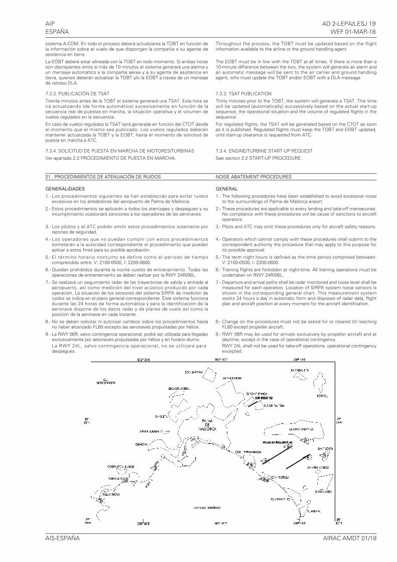
AIP AD 2-LEPA/LESJ 19ESPAÑA WEF 01-MAR-18
sistema A-CDM. En todo el proceso deberá actualizarse la TOBT en función dela información sobre el vuelo de que dispongan la compañía o su agente deasistencia en tierra.
La EOBT deberá estar alineada con la TOBT en todo momento. Si ambas horasson discrepantes entre sí más de 10 minutos el sistema generará una alarma yun mensaje automático a la compañía aérea y a su agente de asistencia entierra, quienes deberán actualizar la TOBT y/o la EOBT a través de un mensajede retraso DLA.
7.3.3. PUBLICACIÓN DE TSAT
Treinta minutos antes de la TOBT el sistema generará una TSAT. Esta hora seirá actualizando (de forma automática) sucesivamente en función de lasecuencia real de puestas en marcha, la situación operativa y el volumen devuelos regulados en la secuencia.
En caso de vuelos regulados la TSAT será generada en función del CTOT desdeel momento que el mismo sea publicado. Los vuelos regulados deberánmantener actualizada la TOBT y la EOBT, hasta el momento de solicitud depuesta en marcha a ATC.
7.3.4. SOLICITUD DE PUESTA EN MARCHA DE MOTORES/TURBINAS
Ver apartado 2.2 PROCEDIMIENTO DE PUESTA EN MARCHA.
21. PROCEDIMIENTOS DE ATENUACIÓN DE RUIDOS
GENERALIDADES
1.- Los procedimientos siguientes se han establecido para evitar ruidosexcesivos en los alrededores del aeropuerto de Palma de Mallorca.
2.- Estos procedimientos se aplicarán a todos los aterrizajes y despegues y suincumplimiento ocasionará sanciones a los operadores de las aeronaves.
3.- Los pilotos y el ATC podrán omitir estos procedimientos solamente porrazones de seguridad.
4.- Los operadores que no puedan cumplir con estos procedimientossometerán a la autoridad correspondiente el procedimiento que puedanaplicar a estos fines para su posible aprobación.
5.- El término horario nocturno se define como el periodo de tiempocomprendido entre: V: 2100-0500, I: 2200-0600.
6.- Quedan prohibidos durante la noche vuelos de entrenamiento. Todas lasoperaciones de entrenamiento se deben realizar por la RWY 24R/06L.
7.- Se realizará un seguimiento radar de las trayectorias de salida y entrada alaeropuerto, así como medición del nivel acústico producido por cadaoperación. La situación de los sensores del sistema SIRPA de medición deruidos se indica en el plano general correspondiente. Este sistema funcionadurante las 24 horas de forma automática y para la identificación de laaeronave dispone de los datos radar y de planes de vuelo así como laposición de la aeronave en cada instante.
8.- No se deben solicitar ni autorizar cambios sobre los procedimientos hastano haber alcanzado FL60 excepto las aeronaves propulsadas por hélice.
9.- La RWY 06R, salvo contingencia operacional, podrá ser utilizada para llegadasexclusivamente por aeronaves propulsadas por hélice y en horario diurno.La RWY 24L, salvo contingencia operacional, no se util izará paradespegues.
Throughout the process, the TOBT must be updated based on the flightinformation available to the airline or the ground handling agent.
The EOBT must be in line with the TOBT at all times. If there is more than a10-minute difference between the two, the system will generate an alarm andan automatic message will be sent to the air carrier and ground handlingagent, who must update the TOBT and/or EOBT with a DLA message.
7.3.3. TSAT PUBLICATION
Thirty minutes prior to the TOBT, the system will generate a TSAT. This timewill be updated (automatically) successively based on the actual start-upsequence, the operational situation and the volume of regulated flights in thesequence.
For regulated flights, the TSAT will be generated based on the CTOT as soonas it is published. Regulated flights must keep the TOBT and EOBT updated,until start-up clearance is requested from ATC.
7.3.4. ENGINE/TURBINE START-UP REQUEST
See section 2.2 START-UP PROCEDURE.
NOISE ABATEMENT PROCEDURES
GENERAL
1.- The following procedures have been established to avoid excessive noiseto the surroundings of Palma de Mallorca airport.
2.- These procedures are applicable to every landing and take-off manoeuvres.No compliance with these procedures will be cause of sanctions to aircraftoperators.
3.- Pilots and ATC may omit these procedures only for aircraft safety reasons.
4.- Operators which cannot comply with these procedures shall submit to thecorrespondent authority the procedure that may apply to this purpose forits possible approval.
5.- The term night hours is defined as the time period comprised between:V: 2100-0500, I: 2200-0600.
6.- Training flights are forbidden at night-time. All training operations must beundertaken on RWY 24R/06L.
7.- Departure and arrival paths shall be radar monitored and noise level shall bemeasured for each operation. Location of SIRPA system noise sensors isshown in the corresponding general chart. This measurement systemworks 24 hours a day in automatic form and disposes of radar data, flightplan and aircraft position at every moment for the aircraft identification.
8.- Change on the procedures must not be asked for or cleared till reachingFL60 except propeller aircraft.
9.- RWY 06R may be used for arrivals exclusively by propeller aircraft and atdaytime, except in the case of operational contingency.RWY 24L shall not be used for take-off operations, operational contingencyexcepted.
AIS-ESPAÑA AIRAC AMDT 01/18
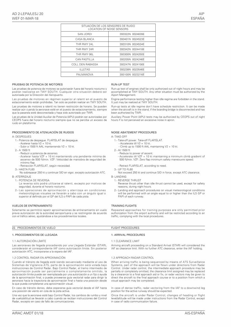
AD 2-LEPA/LESJ 20 AIPWEF 01-MAR-18 ESPAÑA
PRUEBAS DE POTENCIA DE MOTORES
Las pruebas de potencia de motores se autorizarán fuera del horario nocturno ypodrán realizarse en TWY SOUTH. Cualquier otra situación deberá serautorizada por la Dirección del Aeropuerto.
Las pruebas de motores en régimen superior al ralentí en el puesto deestacionamiento están prohibidas. Tan solo se podrán realizar en TWY SOUTH.
Las pruebas de motores a ralentí no tienen restricción de horario. Se puedenrealizar aún cuando la aeronave esté en el puesto de estacionamiento, siempreque la pasarela esté desconectada y haya sido autorizado por TWR.
Las pruebas de la Unidad Auxiliar de Potencia (APU) podrán ser autorizadas porCEOPS fuera del horario nocturno siempre que no se perciba un exceso deruido en plataforma.
PROCEDIMIENTO DE ATENUACIÓN DE RUIDOS
A- DESPEGUES1.- Potencia de despegue. FLAP/SLAT de despegue.
- Acelerar hasta V2 + 10 kt.- Subir a 1500 ft AAL manteniendo V2 + 10 kt.
2.- A 1500 ft- Reducir a potencia de ascenso.- Acelerar hasta VZF + 10 kt manteniendo una pendiente mínima deascenso de 500 ft/min. VZF: Velocidad de maniobra de seguridad demínimo flap.
- Retracción FLAP/SLAT, según necesidad.3.- HASTA FL60
No sobrepasar 250 kt y continuar SID en vigor, excepto autorización ATC.
B- ATERRIZAJE1.- POTENCIA DE REVERSA
La reversa sólo podrá utilizarse al ralentí, excepto por motivos deseguridad, durante el horario nocturno.
2.- Las operaciones de aproximación y aterrizaje en condicionesmeteorológicas visuales se llevarán a cabo con un ángulo igual osuperior al definido por el GP del ILS o PAPI de cada pista.
VUELOS DE ENTRENAMIENTO
Solamente se permitirá repetir aproximaciones de entrenamiento en vueloprevia autorización de la autoridad aeroportuaria y se restringirán de acuerdocon el tráfico aéreo, ajustándose a los procedimientos locales.
22. PROCEDIMIENTOS DE VUELO
1. PROCEDIMIENTOS DE LLEGADA
1.1 AUTORIZACIÓN LÍMITE
Las aeronaves de llegada procediendo por una Llegada Estándar (STAR),considerarán el correspondiente IAF como autorización límite. Sin posteriorautorización ATC, incorporarse a la espera del IAF.
1.2 CONTROL RADAR EN APROXIMACIÓN
Cuando el tránsito de llegada esté siendo secuenciado mediante el uso deSistemas de Vigilancia ATS, parte de la aproximación será volada bajoinstrucciones de Control Radar. Bajo Control Radar, el tramo intermedio deaproximación puede ser parcialmente o completamente omitido, laautorización límite puede ser reemplazada por una autorización a un fijo o ayudade la aproximación final, o puede proveerse guía vectorial radar para dirigir laaeronave hacia la trayectoria de aproximación final o hasta una posición desdela que pueda completarse una aproximación visual.
En caso de tránsito denso, debe esperarse guía vectorial desde el IAF hastauna posición de viento en cola de la pista activa.
Una vez que la aeronave esté bajo Control Radar, los cambios de rumbo y nivelde vuelo/altitud se llevarán a cabo cuando se reciban instrucciones del ControlRadar, excepto en caso de fallo de comunicaciones.
RUN-UP TEST
Run-up test of engines shall be only authorized out of night hours and may beaccomplished at TWY SOUTH. Any other situation must be authorized by theAiport Management.
Engine performance testing higher than idle regime are forbidden in the stand.It just may be realized at TWY SOUTH.
Run-up tests at idle regime don’t have schedule restriction. It can be madewhen the aircraft is in the stand, if the boarding bridge is disconnected and hasbeen authorized by TWR.
Auxiliary Power Point (APU) tests may be authorized by CEOPS out of nighthours if is not perceived an excessive noise in apron.
NOISE ABATEMENT PROCEDURES
A- TAKE-OFF1.- Take-off power. Take-off FLAP/SLAT.
- Accelerate till V2 + 10 kt.- Climb up to 1500 ft AAL maintaining V2 + 10 kt.
2.- At 1500 ft- Reduce to power of ascent.- Accelerate till VZF + 10 kt maintaining a minimum climb gradient of 500 ft/min. VZF: Zero flap minimum safety maneouvre speed.
- Retract FLAP/SLAT, according to need.3.- UP TO FL60
Not exceed 250 kt and continue SID in force, except ATC clearance.
B- LANDING1.- REVERSE THRUST
Reverse thrust other than idle thrust cannot be used, except for safetyreasons, during night hours.
2.- Landing and approach procedures on visual meteorological conditionswill be performed with an angle equal to or higher than the ILS GP orPAPI of each runway.
TRAINING FLIGHTS
Repeated approaches for training purposes are only permitted priorauthorization from the airport authority and will be restricted according to airtraffic, complying with the local procedures.
FLIGHT PROCEDURES
1. ARRIVAL PROCEDURES
1.1 CLEARANCE LIMIT
Arriving aircraft proceeding on a Standard Arrival (STAR) will considered theIAF as clearance limit. With no further ATC clearance, enter the IAF holding.
1.2 APPROACH RADAR CONTROL
When arriving traffic is being sequenced by means of ATS SurveillanceSystems, part of the approach will be flown under directions from RadarControl. Under radar control, the intermediate approach procedure may bepartially or completely omitted, the clearance limit assigned may be replacedby a clearance to a final approach aid or fix, or radar vectors may be given todirect the aircraft to the final approach course or to a position from which avisual approach may be completed.
In case of dense traffic, radar vectoring from the IAF to a downwind legposition for the active runway should be expected.
Once the aircraft is under Radar Control, changes of heading or flightlevel/altitude will be made under instructions from the Radar Control, exceptin case of radio communication failure.
AIRAC AMDT 01/18 AIS-ESPAÑA
SITUACIÓN DE LOS SENSORES DE RUIDOLOCATION OF NOISE SENSORS
SAN JORDI 393322N 0024639E
CASA BLANCA 393401N 0024523E
THR RWY 24L 393310N 0024534E
THR RWY 24R 393342N 0024418E
THR RWY 06L 393300N 0024250E
CAN PASTILLA 393205N 0024246E
COLL DEN RABASSA 393247N 0024156E
ILLETAS 393238N 0023546E
PALMANOVA 393100N 0023216E
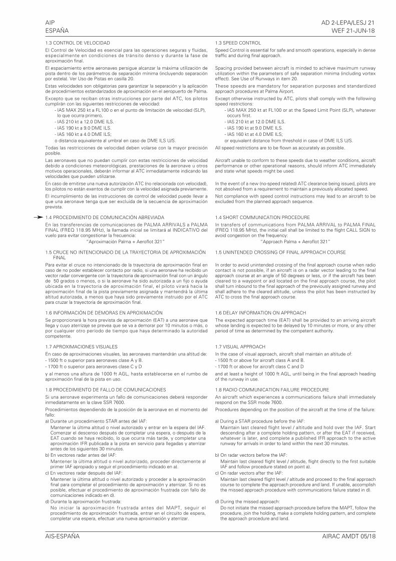
AIP AD 2-LEPA/LESJ 21ESPAÑA WEF 21-JUN-18
AIS-ESPAÑA AIRAC AMDT 05/18
1.3 CONTROL DE VELOCIDAD
El Control de Velocidad es esencial para las operaciones seguras y fluidas,especialmente en condiciones de tránsito denso y durante la fase deaproximación final.
El espaciamiento entre aeronaves persigue alcanzar la máxima utilización depista dentro de los parámetros de separación mínima (incluyendo separaciónpor estela). Ver Uso de Pistas en casilla 20.
Estas velocidades son obligatorias para garantizar la separación y la aplicaciónde procedimientos estandarizados de aproximación en el aeropuerto de Palma.
Excepto que se reciban otras instrucciones por parte del ATC, los pilotoscumplirán con las siguientes restricciones de velocidad:
- IAS MAX 250 kt a FL100 o en el punto de limitación de velocidad (SLP),lo que ocurra primero,
- IAS 210 kt a 12.0 DME ILS.- IAS 190 kt a 9.0 DME ILS.- IAS 160 kt a 4.0 DME ILS;o distancia equivalente al umbral en caso de DME ILS U/S.
Todas las restricciones de velocidad deben volarse con la mayor precisiónposible.
Las aeronaves que no puedan cumplir con estas restricciones de velocidaddebido a condiciones meteorológicas, prestaciones de la aeronave u otrosmotivos operacionales, deberán informar al ATC inmediatamente indicando lasvelocidades que pueden utilizarse.
En caso de emitirse una nueva autorización ATC (no relacionada con velocidad),los pilotos no están exentos de cumplir con la velocidad asignada previamente.
El incumplimiento de las instrucciones de control de velocidad puede llevar aque una aeronave tenga que ser excluida de la secuencia de aproximaciónprevista.
1.4 PROCEDIMIENTO DE COMUNICACIÓN ABREVIADA
En las transferencias de comunicaciones de PALMA ARRIVALS a PALMAFINAL (FREQ 118.95 MHz), la llamada inicial se limitará al INDICATIVO delvuelo para evitar congestionar la frecuencia:
“Aproximación Palma + Aeroflot 321”
1.5 CRUCE NO INTENCIONADO DE LA TRAYECTORIA DE APROXIMACIÓNFINAL
Para evitar el cruce no intencionado de la trayectoria de aproximación final encaso de no poder establecer contacto por radio, si una aeronave ha recibido unvector radar convergente con la trayectoria de aproximación final con un ángulode 50 grados o menos, o si la aeronave ha sido autorizada a un fijo o ayudaubicada en la trayectoria de aproximación final, el piloto virará hacia laaproximación final de la pista previamente asignada y mantendrá la últimaaltitud autorizada, a menos que haya sido previamente instruido por el ATCpara cruzar la trayectoria de aproximación final.
1.6 INFORMACIÓN DE DEMORAS EN APROXIMACIÓN
Se proporcionará la hora prevista de aproximación (EAT) a una aeronave quellega y cuyo aterrizaje se prevea que se va a demorar por 10 minutos o más, opor cualquier otro período de tiempo que haya determinado la autoridadcompetente.
1.7 APROXIMACIONES VISUALES
En caso de aproximaciones visuales, las aeronaves mantendrán una altitud de:- 1500 ft o superior para aeronaves clase A y B.- 1700 ft o superior para aeronaves clase C y D
y al menos una altura de 1000 ft AGL, hasta establecerse en el rumbo deaproximación final de la pista en uso.
1.8 PROCEDIMIENTO DE FALLO DE COMUNICACIONES
Si una aeronave experimenta un fallo de comunicaciones deberá responderinmediatamente en la clave SSR 7600.
Procedimientos dependiendo de la posición de la aeronave en el momento delfallo:a) Durante un procedimiento STAR antes del IAF:
Mantener la última altitud o nivel autorizado y entrar en la espera del IAF.Comenzar el descenso después de completar una espera, o después de laEAT cuando se haya recibido, lo que ocurra más tarde, y completar unaaproximación IFR publicada a la pista en servicio para llegadas y aterrizarantes de los siguientes 30 minutos.
b) En vectores radar antes del IAF:Mantener la última altitud o nivel autorizado, proceder directamente alprimer IAF apropiado y seguir el procedimiento indicado en a).
c) En vectores radar después del IAF:Mantener la última altitud o nivel autorizado y proceder a la aproximaciónfinal para completar el procedimiento de aproximación y aterrizar. Si no esposible, efectuar el procedimiento de aproximación frustrada con fallo decomunicaciones indicado en d).
d) Durante la aproximación frustrada:No iniciar la aproximación frustrada antes del MAPT, seguir elprocedimiento de aproximación frustrada, entrar en el circuito de espera,completar una espera, efectuar una nueva aproximación y aterrizar.
1.3 SPEED CONTROL
Speed Control is essential for safe and smooth operations, especially in densetraffic and during final approach.
Spacing provided between aircraft is minded to achieve maximum runwayutilization within the parameters of safe separation minima (including vortexeffect). See Use of Runways in item 20.
These speeds are mandatory for separation purposes and standardizedapproach procedures at Palma Airport.
Except otherwise instructed by ATC, pilots shall comply with the followingspeed restrictions:
- IAS MAX 250 kt at FL100 or at the Speed Limit Point (SLP), whateveroccurs first.
- IAS 210 kt at 12.0 DME ILS.- IAS 190 kt at 9.0 DME ILS.- IAS 160 kt at 4.0 DME ILS;or equivalent distance from threshold in case of DME ILS U/S.
All speed restrictions are to be flown as accurately as possible.
Aircraft unable to conform to these speeds due to weather conditions, aircraftperformance or other operational reasons, should inform ATC immediatelyand state what speeds might be used.
In the event of a new (no-speed related) ATC clearance being issued, pilots arenot absolved from a requirement to maintain a previously allocated speed.
Not compliance with speed control instructions may lead to an aircraft to beexcluded from the planned approach sequence.
1.4 SHORT COMMUNICATION PROCEDURE
In transfers of communications from PALMA ARRIVAL to PALMA FINAL(FREQ 118.95 MHz), the initial call shall be limited to the flight CALL SIGN toavoid congestion on the frequency:
“Approach Palma + Aeroflot 321”
1.5 UNINTENDED CROSSING OF FINAL APPROACH COURSE
In order to avoid unintended crossing of the final approach course when radiocontact is not possible, if an aircraft is on a radar vector leading to the finalapproach course at an angle of 50 degrees or less, or if the aircraft has beencleared to a waypoint or aid located on the final approach course, the pilotshall turn inbound to the final approach of the previously assigned runway andshall adhere to the cleared altitude, unless the pilot has been instructed byATC to cross the final approach course.
1.6 DELAY INFORMATION ON APPROACH
The expected approach time (EAT) shall be provided to an arriving aircraftwhose landing is expected to be delayed by 10 minutes or more, or any otherperiod of time as determined by the competent authority.
1.7 VISUAL APPROACH
In the case of visual approach, aircraft shall maintain an altitude of:- 1500 ft or above for aircraft class A and B.- 1700 ft or above for aircraft class C and D
and at least a height of 1000 ft AGL, until being in the final approach headingof the runway in use.
1.8 RADIO COMMUNICATION FAILURE PROCEDURE
An aircraft which experiences a communications failure shall immediatelyrespond on the SSR mode 7600.
Procedures depending on the position of the aircraft at the time of the failure:
a) During a STAR procedure before the IAF:Maintain last cleared flight level / altitude and hold over the IAF. Startdescending after a complete holding pattern, or after the EAT if received,whatever is later, and complete a published IFR approach to the activerunway for arrivals in order to land within the next 30 minutes.
b) On radar vectors before the IAF:Maintain last cleared flight level / altitude, flight directly to the first suitableIAF and follow procedure stated on point a).
c) On radar vectors after the IAF:Maintain last cleared flight level / altitude and proceed to the final approachcourse to complete the approach procedure and land. If unable, accomplishthe missed approach procedure with communications failure stated in d).
d) During the missed approach:Do not initiate the missed approach procedure before the MAPT, follow theprocedure, join the holding, make a complete holding pattern, and completethe approach procedure and land.
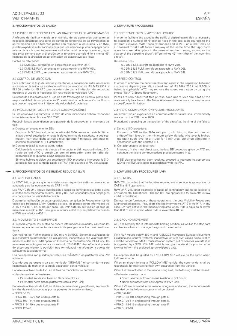
AD 2-LEPA/LESJ 22 AIPWEF 01-MAR-18 ESPAÑA
AIRAC AMDT 01/18 AIS-ESPAÑA
2. PROCEDIMIENTOS DE SALIDA
2.1 PUNTOS DE REFERENCIA EN LAS TRAYECTORIAS DE APROXIMACIÓN
A efectos de facilitar y acelerar el tránsito de las aeronaves que salen esnecesario establecer una serie de puntos de referencia en las trayectorias deaproximación a las diferentes pistas con respecto a los cuales, y en IMC,puedan expedirse autorizaciones para que una aeronave pueda despegar por lamisma pista a la que otra aeronave está efectuando una aproximación, o porotra pista siempre que la dirección de la aeronave que sale difiera menos 45°respecto de la dirección de aproximación de la aeronave que llega.
Puntos de referencia:- 5.0 DME SSJ, aeronaves en aproximación a la RWY 24R.- 5.0 DME ILS PLM, aeronaves en aproximación a la RWY 06L.- 5.0 DME ILS IPAL, aeronaves en aproximación a la RWY 24L.
2.2 CONTROL DE VELOCIDAD
Para optimizar el flujo de salidas y mantener la separación entre aeronavessucesivas en la salida, se establece un límite de velocidad de IAS MAX 250 kt aFL100 o inferior. El ATC puede eximir de dicha limitación de velocidadmediante el uso de la fraselogía ‘Sin restricción de velocidad ATC’.
Se recuerda a los pilotos que el uso de esta fraseología no exime al piloto de laresponsabilidad de cumplir con los Procedimientos de Atenuación de Ruidosque pueden requerir una limitación de velocidad y/o potencia.
2.3 PROCEDIMIENTOS DE FALLO DE COMUNICACIONES
Si una aeronave experimenta un fallo de comunicaciones deberá responderinmediatamente en la clave SSR 7600.
Procedimientos dependiendo de la posición de la aeronave en el momento delfallo:a) Durante un procedimiento SID:
Continuar la SID hasta el punto de salida del TMA, ascender hasta la últimaaltitud o nivel autorizado, o hasta la altitud mínima de seguridad, la que seamayor, mantener dicha altitud o nivel durante 7 minutos, continuar elascenso de acuerdo al FPL actualizado.
b) Durante una salida con vectores radar:Dirigirse de la manera más directa a interceptar el último procedimiento SIDrecibido del ATC y continuar con el procedimiento de fal lo decomunicaciones durante la SID indicado en a).Si no se hubiera recibido una autorización SID, proceder a interceptar la SIDapropiada hasta el punto de salida del TMA y de acuerdo al FPL actualizado.
3. PROCEDIMIENTOS DE VISIBILIDAD REDUCIDA (LVP)
3.1. GENERALIDADES
La RWY 24L, sujeta a que las instalaciones requeridas estén en servicio, esadecuada para las operaciones de CAT II y III.
Las RWY 24R, 24L (previa autorización o casos de contingencia al estar sujetaa limitaciones medioambientales), 06R y 06L son adecuadas para despeguesen condiciones de visibilidad reducida.
Durante la realización de estas operaciones, se aplicarán Procedimientos deVisibilidad Reducida (LVP). Cuando así sea, los pilotos serán informados víaATIS o vía RTF. En cualquier caso, los LVP estarán activos en el área demaniobras cuando el RVR sea igual o inferior a 650 m y en plataforma cuandoel RVR sea inferior a 400 m.
3.2. MOVIMIENTO EN SUPERFICIE
ATC podrá emplear los puntos de espera intermedios iluminados, así como lasbarras de parada como autorizaciones límite para gestionar los movimientos entierra.
Con valores de RVR menores a 400 m y A-SMGCS (Sistemas avanzados deguía y control de movimiento en la superficie) inoperativo o con valores de RVRmenores a 400 m y SMR operativo (Sistema de multilateración MLAT u/s), lasaeronaves rodarán guiadas por un vehículo “SÍGAME” desde/hacia el puestode estacionamiento (o posición tras remolcado) hacia/desde la puerta desalida/entrada a plataforma.
Los helicópteros irán guiados por vehículos “SÍGAME” en plataforma con LVPactivado.
Cuando una aeronave siga a un vehículo “SÍGAME” el comandante seráresponsable de mantener la propia separación con el vehículo.
En fase de activación de LVP en el área de maniobras, se cerrarán:
– Vías de servicio perimetrales:• Perimetral sur desde Aviación General a SEI sur.• Perimetral norte desde plataforma este a TWY Link
En fase de activación de LVP en el área de maniobras y plataforma, se cerraránlas vías de servicio acotadas por los puestos de estacionamiento:– PRKG 6-103.– PRKG 103-104 y que cruza puerta D.– PRKG 109-114 y que cruza puerta E.– PRKG 118-119 y que cruza puerta F.– PRKG 123-48.
2. DEPARTURE PROCEDURES
2.1 REFERENCE FIXES IN APPROACH COURSE
In order to facilitate and expedite the traffic of departing aircraft it is necessaryto establish a number of reference fixes in the approach courses to thedifferent runways. With these references and in IMC, an aircraft may beauthorized to take off from a runway at the same time that approachoperations are taking place in the same or another runway, as long as thecourse of the departing aircraft differs minus 45° from that of the incomingaircraft.
Reference fixes:- 5.0 DME SSJ, aircraft on approach to RWY 24R.- 5.0 DME ILS PLM, aircraft on approach to RWY 06L.- 5.0 DME ILS IPAL, aircraft on approach to RWY 24L.
2.2 SPEED CONTROL
In order to optimize the departure flow and assist in the separation betweensuccessive departing aircraft, a speed limit of IAS MAX 250 kt at FL100 orbelow is applicable. ATC may remove the speed restriction by using thephrase ‘No ATC Speed Restriction’.
Pilots are reminded that this phrase does not relieve the pilot of theresponsibility to adhere to the Noise Abatement Procedures that may requirea speed/power limitation.
2.3 RADIO COMMUNICATION FAILURE PROCEDURES
An aircraft which experiences a communications failure shall immediatelyrespond on the SSR mode 7600.
Procedures depending on the position of the aircraft at the time of the failure:
a) During a SID procedure:Follow the SID to the TMA exit point, climbing to the last clearedaltitude/flight level, or the minimum safety altitude, whatever is higher;maintain such level or altitude for 7 minutes, continue climbing inaccordance with the updated FPL.
b) On radar vectors on departure:Intercept, in the most direct way, the last SID procedure given by ATC andcontinue the failure communications procedure stated in a).
If SID clearance has not been received, proceed to intercept the appropriateSID to the TMA exit point in accordance with the FPL.
3. LOW VISIBILITY PROCEDURES (LVP)
3.1. GENERAL
RWY 24L, provided that the facilities required are in service, is appropriate forCAT II and III operations.
RWY 24R, 24L (prior clearance or cases of contingency due to be subject toenvironmental limitations), 06R and 06L are appropriate for take-offs in lowvisibility conditions.
During the performance of these operations, the Low Visibility Procedures(LVP) shall be applied. If so, pilots shall be informed via ATIS or via RTF. In anycase, LVP are active in the manoeuvring area when RVR is equal to or lowerthan 650 m and in apron when RVR is lower than 400 m.
3.2. GROUND MOVEMENT
ATC shall employ the lit intermediate holding position, as well as the stop barsas clearance limits to manage the ground movements.
With RVR values below 400 m and A-SMGCS (Advanced Surface MovementGuidance and Control Systems) inoperative, or with RVR values below 400 mand SMR operative (MLAT multilateration system out of service), aircraft shalltaxi guided by a "FOLLOW ME" vehicle from/to the stand (or position aftertowing) to/from the assigned apron exit/entry gate.
Helicopters shall be guided by a "FOLLOW ME" vehicle on the apron whenLVP are in force.
When an aircraft follows a "FOLLOW ME" vehicle, the commander shall beresponsible for maintaining their own separation from the vehicle.
When LVP are activated in the manoeuvring area, the following shall be closed:
– Perimeter service roads:• South perimeter from General Aviation to SEI South.• North perimeter from East Apron to TWY Link.
When LVP are activated in the manoeuvring area and apron, the service roadsbounded by the following stands shall be closed:– PRKG 6-103.– PRKG 103-104 and passing through gate D.– PRKG 109-114 and passing through gate E.– PRKG 118-119 and passing through gate F.– PRKG 123-48.
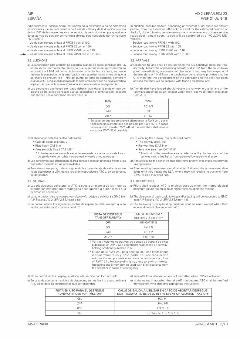
AIP AD 2-LEPA/LESJ 23ESPAÑA WEF 21-JUN-18
AIS-ESPAÑA AIRAC AMDT 05/18
Adicionalmente, posible cierre, en función de la existencia o no de aeronavesestacionadas, de su hora prevista de fuera de calzos y de la duración previstade los LVP, de las siguientes vías de servicio de vehículos (siempre que algunade estas vías de servicio permanezca abierta, será controlado por un vehículo“SÍGAME”):– Vía de servicio que enlaza el PRKG 1 con el 100.– Vía de servicio que enlaza el PRKG 22 con el 109.– Vía de servicio que enlaza el PRKG 25/26 con el 116.– Vía de servicio que enlaza el PRKG 28/29 con el 121-123.
3.3. LLEGADAS
a) La autorización para aterrizar se expedirá cuando las áreas sensibles del ILSestén libres, normalmente, antes de que la aeronave en aproximación seencuentre a 2 NM del punto de toma de contacto. No obstante, se puederetrasar la concesión de la autorización para aterrizar hasta antes de que laaeronave se encuentre a 1 NM del punto de toma de contacto, siempre ycuando el CTA vigile el desarrollo de la aproximación y que se haya advertidoal piloto de que se le suministrará una autorización de aterrizaje tardía.
b) Las aeronaves que hayan aterrizado deberán abandonar la pista en uso poralguna de las calles de rodaje que se especifican a continuación, exceptoque reciban una autorización distinta del ATC:
c) Al abandonar pista los pilotos notificarán:• Calle de salida utilizada, y• Pista libre ( CAT I), o• Área sensible libre ( CAT II/III)*
* El límite del área sensible viene determinada por la transición de lucesde eje de calle de rodaje verde-amarillo- verde a todas verdes.
d) Las aeronaves que abandonen el área sensible tendrán prioridad frente a lasque estén rodando en las proximidades.
e) Tras abandonar pista, rodarán siguiendo las luces de eje de calle de rodajehasta abandonar la LSA, donde recibirán instrucciones ATC o, en su defecto,se detendrán.
3.4. SALIDAS
a) Las tripulaciones solicitarán al ATC la puesta en marcha de los motorescuando los mínimos meteorológicos sean iguales o superiores a susmínimos de operación.
b) La autorización para retroceso, remolcado y/o rodaje se solicitará a GMC (verAIP-España, AD 2-LEPA/LESJ casilla 18).
c) Se podrán utilizar los siguientes puntos de espera de pista, excepto que sereciba una autorización distinta del ATC:
d) No se permitirán los despegues desde intersección con LVP activado.
e) En caso de abortar la maniobra de despegue, se notificará lo antes posible aATC quien dará las instrucciones que correspondan.
In addition, possible closure, depending on whether or not there are aircraftparked, from the estimated off-block time and for the estimated duration ofthe LVP, of the following vehicle service roads (whenever any of these serviceroads does remain open, its use will be controlled by a "FOLLOW ME"vehicle).– Service road linking PRKG 1 with 100.– Service road linking PRKG 22 with 109.– Service road linking PRKG 25/26 with 116.– Service road linking PRKG 28/29 with 121-123.
3.3. ARRIVALS
a) Clearance to land shall be issued when the ILS sensitive areas are free,normally, before the approaching aircraft is at 2 NM from the touchdownpoint. Nevertheless, concession of clearance to land may be delayed untilthe aircraft is at 1 NM from the touchdown point, always provided that theCTA monitors the development of the approach and the pilot has beenadvised that they will be supplied with landing clearance late.
b) Aircraft that have landed should vacate the runway in use by any of thetaxiways specified below, except when they receive different clearancefrom ATC:
c) On vacating the runway, the pilots shall notify:• The taxiway used, and• Runway free (CAT I), or• Sensitive area free (CAT II/III)*
* The limit of the sensitive area is determined by the transition of thetaxiway centre line lights from green-yellow-green to all green.
d) Aircraft leaving the sensitive area shall have priority over those that may betaxiing nearby.
e) After vacating the runway, aircraft shall taxi following the taxiway centrelinelights until they vacate the LSA, where they will receive instructions fromGMC, or else they shall halt.
3.4. DEPARTURES
a) Pilots shall request ATC to engines start-up when the meteorologicalminimum values are equal to or higher than its operation minima.
b) The clearance of push-back, towing and/or taxiing will be requested to GMC(see AIP-España, AD 2-LEPA/LESJ item 18).
c) The following runway-holding positions shall be used, except when theyreceive different clearance from ATC.
d) Take-offs from intersection are not permitted when LVP are activated.
e) In the event of aborting the take-off manoeuvre, ATC shall be notifiedimmediately, who shall give appropriate instructions.
RWY TWY
06L N2, N3
24R N4
24L* S1, S2
* En caso de que las aeronaves abandonen la RWY 24L por elfinal lo harán siempre que sea posible por TWY H7. / In caseswhere aircraft vacate RWY 24L at the end, they shall alwaysdo so via TWY H7 if possible.
PISTA DE DESPEGUETAKE-OFF RUNWAY
PUNTO DE ESPERA *HOLDING POSITION *
06R H8 (CAT II/III)
06L H4, H5
24R H1, H2
24L** H9, H10
* Ver restricciones operativas de puntos de espera de pistapublicadas en AIP. / See operational restrictions on runway-holding positions published in AIP.
** El uso de la RWY 24L para despegues tiene limitacionesmedioambientales y sólo podrá ser uti l izada previaautorización aeroportuaria o en casos de contingencia. / Useof RWY 24L for take-offs is subject to environmentallimitations and it may only be used with prior clearance fromthe airport or in cases of contingency.
PISTA EN USO PARA EL DESPEGUERUNWAY IN USE FOR TAKE-OFF
CALLE DE SALIDA A UTILIZAR EN CASO DE ABORTAR DESPEGUEEXIT TAXIWAY TO BE USED IN THE EVENT OF ABORTED TAKE-OFF
06L H2 / H1
24R H4 / H5
06R H9 / H10
24L S1 / S2 / S3 / H8 / H7 / H6
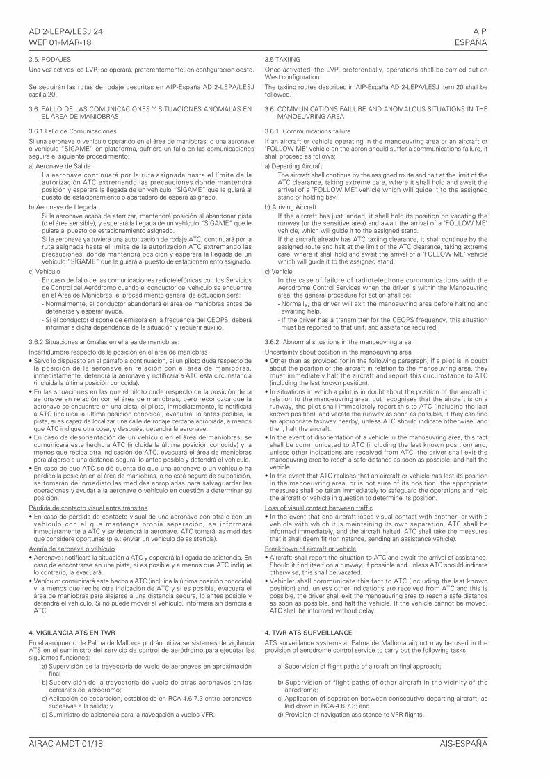
AD 2-LEPA/LESJ 24 AIPWEF 01-MAR-18 ESPAÑA
AIRAC AMDT 01/18 AIS-ESPAÑA
3.5. RODAJES
Una vez activos los LVP, se operará, preferentemente, en configuración oeste.
Se seguirán las rutas de rodaje descritas en AIP-España AD 2-LEPA/LESJcasilla 20.
3.6. FALLO DE LAS COMUNICACIONES Y SITUACIONES ANÓMALAS ENEL ÁREA DE MANIOBRAS
3.6.1 Fallo de Comunicaciones
Si una aeronave o vehículo operando en el área de maniobras, o una aeronaveo vehículo “SÍGAME” en plataforma, sufriera un fallo en las comunicacionesseguirá el siguiente procedimiento:
a) Aeronave de SalidaLa aeronave continuará por la ruta asignada hasta el l ímite de laautorización ATC extremando las precauciones donde mantendráposición y esperará la llegada de un vehículo “SÍGAME” que le guiará alpuesto de estacionamiento o apartadero de espera asignado.
b) Aeronave de LlegadaSi la aeronave acaba de aterrizar, mantendrá posición al abandonar pista(o el área sensible), y esperará la llegada de un vehículo “SÍGAME” que leguiará al puesto de estacionamiento asignado.Si la aeronave ya tuviera una autorización de rodaje ATC, continuará por laruta asignada hasta el límite de la autorización ATC extremando lasprecauciones, donde mantendrá posición y esperará la llegada de unvehículo “SÍGAME” que le guiará al puesto de estacionamiento asignado.
c) VehículoEn caso de fallo de las comunicaciones radiotelefónicas con los Serviciosde Control del Aeródromo cuando el conductor del vehículo se encuentreen el Área de Maniobras, el procedimiento general de actuación será:- Normalmente, el conductor abandonará el área de maniobras antes dedetenerse y esperar ayuda.
- Si el conductor dispone de emisora en la frecuencia del CEOPS, deberáinformar a dicha dependencia de la situación y requerir auxilio.
3.6.2 Situaciones anómalas en el área de maniobras:
Incertidumbre respecto de la posición en el área de maniobras• Salvo lo dispuesto en el párrafo a continuación, si un piloto duda respecto de
la posición de la aeronave en relación con el área de maniobras,inmediatamente, detendrá la aeronave y notificará a ATC esta circunstancia(incluida la última posición conocida).
• En las situaciones en las que el piloto dude respecto de la posición de laaeronave en relación con el área de maniobras, pero reconozca que laaeronave se encuentra en una pista, el piloto, inmediatamente, lo notificaráa ATC (incluida la última posición conocida), evacuará, lo antes posible, lapista, si es capaz de localizar una calle de rodaje cercana apropiada, a menosque ATC indique otra cosa; y después, detendrá la aeronave.
• En caso de desorientación de un vehículo en el área de maniobras, secomunicará este hecho a ATC (incluida la última posición conocida) y, amenos que reciba otra indicación de ATC, evacuará el área de maniobraspara alejarse a una distancia segura, lo antes posible y detendrá el vehículo.
• En caso de que ATC se dé cuenta de que una aeronave o un vehículo haperdido la posición en el área de maniobras, o no esté seguro de su posición,se tomarán de inmediato las medidas apropiadas para salvaguardar lasoperaciones y ayudar a la aeronave o vehículo en cuestión a determinar suposición.
Pérdida de contacto visual entre tránsitos• En caso de pérdida de contacto visual de una aeronave con otra o con un
vehículo con el que mantenga propia separación, se informaráinmediatamente a ATC y se detendrá la aeronave. ATC tomará las medidasque considere oportunas (p.e.: enviar un vehículo de asistencia).
Avería de aeronave o vehículo• Aeronave: notificará la situación a ATC y esperará la llegada de asistencia. En
caso de encontrarse en una pista, si es posible y a menos que ATC indiquelo contrario, la evacuará.
• Vehículo: comunicará este hecho a ATC (incluida la última posición conocida)y, a menos que reciba otra indicación de ATC y si es posible, evacuará elárea de maniobras para alejarse a una distancia segura, lo antes posible ydetendrá el vehículo. Si no puede mover el vehículo, informará sin demora aATC.
4. VIGILANCIA ATS EN TWR
En el aeropuerto de Palma de Mallorca podrán utilizarse sistemas de vigilanciaATS en el suministro del servicio de control de aeródromo para ejecutar lassiguientes funciones:
a) Supervisión de la trayectoria de vuelo de aeronaves en aproximaciónfinal
b) Supervisión de la trayectoria de vuelo de otras aeronaves en lascercanías del aeródromo;
c) Aplicación de separación, establecida en RCA-4.6.7.3 entre aeronavessucesivas a la salida; y
d) Suministro de asistencia para la navegación a vuelos VFR.
3.5 TAXIING
Once activated the LVP, preferentially, operations shall be carried out onWest configuration
The taxiing routes described in AIP-España AD 2-LEPA/LESJ item 20 shall befollowed.
3.6. COMMUNICATIONS FAILURE AND ANOMALOUS SITUATIONS IN THEMANOEUVRING AREA
3.6.1. Communications failure
If an aircraft or vehicle operating in the manoeuvring area or an aircraft or"FOLLOW ME" vehicle on the apron should suffer a communications failure, itshall proceed as follows:
a) Departing AircraftThe aircraft shall continue by the assigned route and halt at the limit of theATC clearance, taking extreme care, where it shall hold and await thearrival of a "FOLLOW ME" vehicle which will guide it to the assignedstand or holding bay.
b) Arriving AircraftIf the aircraft has just landed, it shall hold its position on vacating therunway (or the sensitive area) and await the arrival of a "FOLLOW ME"vehicle, which will guide it to the assigned stand.If the aircraft already has ATC taxiing clearance, it shall continue by theassigned route and halt at the limit of the ATC clearance, taking extremecare, where it shall hold and await the arrival of a "FOLLOW ME" vehiclewhich will guide it to the assigned stand.
c) VehicleIn the case of failure of radiotelephone communications with theAerodrome Control Services when the driver is within the Manoeuvringarea, the general procedure for action shall be:- Normally, the driver will exit the manoeuvring area before halting andawaiting help.
- If the driver has a transmitter for the CEOPS frequency, this situationmust be reported to that unit, and assistance required.
3.6.2. Abnormal situations in the manoeuvring area:
Uncertainty about position in the manoeuvring area• Other than as provided for in the following paragraph, if a pilot is in doubt
about the position of the aircraft in relation to the manoeuvring area, theymust immediately halt the aircraft and report this circumstance to ATC(including the last known position).
• In situations in which a pilot is in doubt about the position of the aircraft inrelation to the manoeuvring area, but recognises that the aircraft is on arunway, the pilot shall immediately report this to ATC (including the lastknown position), and vacate the runway as soon as possible, if they can findan appropriate taxiway nearby, unless ATC should indicate otherwise, andthen, halt the aircraft.
• In the event of disorientation of a vehicle in the manoeuvring area, this factshall be communicated to ATC (including the last known position) and,unless other indications are received from ATC, the driver shall exit themanoeuvring area to reach a safe distance as soon as possible, and halt thevehicle.
• In the event that ATC realises that an aircraft or vehicle has lost its positionin the manoeuvring area, or is not sure of its position, the appropriatemeasures shall be taken immediately to safeguard the operations and helpthe aircraft or vehicle in question to determine its position.
Loss of visual contact between traffic• In the event that one aircraft loses visual contact with another, or with a
vehicle with which it is maintaining its own separation, ATC shall beinformed immediately, and the aircraft halted. ATC shall take the measuresthat it shall deem fit (for instance, sending an assistance vehicle).
Breakdown of aircraft or vehicle• Aircraft: shall report the situation to ATC and await the arrival of assistance.
Should it find itself on a runway, if possible and unless ATC should indicateotherwise, this shall be vacated.
• Vehicle: shall communicate this fact to ATC (including the last knownposition) and, unless other indications are received from ATC and this ispossible, the driver shall exit the manoeuvring area to reach a safe distanceas soon as possible, and halt the vehicle. If the vehicle cannot be moved,ATC shall be informed without delay.
4. TWR ATS SURVEILLANCE
ATS surveillance systems at Palma de Mallorca airport may be used in theprovision of aerodrome control service to carry out the following tasks:
a) Supervision of flight paths of aircraft on final approach;
b) Supervision of flight paths of other aircraft in the vicinity of theaerodrome;
c) Application of separation between consecutive departing aircraft, aslaid down in RCA-4.6.7.3; and
d) Provision of navigation assistance to VFR flights.
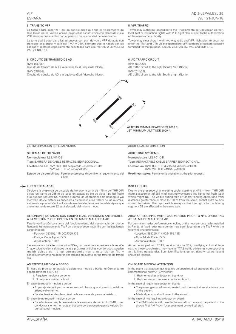
AIP AD 2-LEPA/LESJ 25ESPAÑA WEF 21-JUN-18
AIS-ESPAÑA AIRAC AMDT 05/18
5. TRÁNSITO VFR
La torre podrá autorizar, en las condiciones que fija el Reglamento deCirculación Aérea, vuelos locales, de pruebas o instrucción con planes de vueloVFR siempre que cuenten con el permiso de la autoridad del aeródromo.
La torre podrá autorizar a las aeronaves con plan de vuelo VFR dotadas contransceptor a entrar y salir del TMA y CTR, siempre que lo hagan por lospasillos y sectores especialmente habilitados para ello. Ver AD 2-LEPA/LESJVAC y ENR 6.10.
6. CIRCUITO DE TRÁNSITO DE AD
RWY 06L/06RCircuito de tránsito de AD a la derecha (Sur) / izquierda (Norte).
RWY 24R/24LCircuito de tránsito de AD a la izquierda (Sur) / derecha (Norte).
23. INFORMACIÓN SUPLEMENTARIA
SISTEMAS DE FRENADO
Nomenclatura: LESJ-01-C-B.
Tipo: BARRERA DE CABLE RETRÁCTIL BIDIRECCIONAL.
Localización en: RWY 06R THR desplazado +650m/+2133ft.RWY 24L THR +1940m/+6365ft.
Estado de disponibilidad: Permanentemente disponible, a requerimiento delpiloto.
LUCES ENRASADAS
Debido a la presencia de un cable de frenado, a partir de 475 m del THR 06Rexiste un tramo de 285 m de luces enrasadas de eje de pista (tipo full-flush)que pueden resultar NO visibles durante las operaciones de despegue y/oaterrizaje desde distancias superiores o cercanas a los 100 m de las mismas,extremen la precaución. Las luces de eje de calle de rodaje de salida rápida queune el tramo de rodaje S2 está afectado del mismo modo.
AERONAVES DOTADAS CON EQUIPO TCAS, VERSIONES ANTERIORESA LA VERSIÓN 7, QUE OPEREN EN PALMA DE MALLORCA AD
Para la verificación constante del funcionamiento del nuevo radar de ruta deRanda se ha instalado en la TWR un transpondedor radar fijo con las siguientescaracterísticas:
- Posición: 393255.11N 0024359.13E- Código Modo Alpha: 7777- Altura antena: 100 ft
Las aeronaves dotadas con equipo TCAs, con versiones anteriores a la versión7, que sobrevuelen a altitudes bajas y próximas a dichas coordenadas, puedenrecibir avisos de tráfico correspondientes a este blanco fi jo yconsecuentemente no deberán ser tenidos en cuenta por no tratarse de tráficoreal.
ASISTENCIA MÉDICA A BORDO
En caso de precisar un pasajero asistencia médica a bordo, el Comandantedeberá notificar a ATC si:
1. Requiere médico a bordo, o2. No requiere médico a bordo.
En caso de requerir médico a bordo:• El pasaje deberá permanecer sentado hasta que el servicio médico
atienda el enfermo.• Se efectuará el desplazamiento a la aeronave de personal médico.
En caso de no requerir médico a bordo:• Se efectuará desplazamiento a la aeronave de vehículo PMR, que
conducirá al enfermo hasta el botiquín del aeropuerto para la valoraciónpor personal médico.
5. VFR TRAFFIC
Tower may authorize, according to the “Reglamento de Circulación Aérea”,local, test or instruction flights with VFR flight plan subject to the authorizationof the aerodrome authority.
Tower may clear aircraft with two way radio and VFR flight plan, to depart orenter the TMA and CTR via the appropriate VFR corridors or sectors speciallyfurnished for that purpose. See AD 2-LEPA/LESJ VAC and ENR 6.10.
6. AD TRAFFIC CIRCUIT
RWY 06L/06RAD traffic circuit to the right (South) / left (North).
RWY 24R/24LAD traffic circuit to the left (South) / right (North).
ADDITIONAL INFORMATION
ARRESTING SYSTEMS
Nomenclature: LESJ-01-C-B.
Type: RETRACTABLE CABLE BARRIER BIDIRECTIONAL.
Location on: RWY 06R THR displaced +650m/+2133ft.RWY 24L THR +1940m/+6365ft.
Readiness status: Permanently available, at the pilot request.
INSET LIGHTS
Due to the presence of a arresting cable, starting at 475 m from THR 06Rthere is a segment of 285 m of inset runway centre line lights (full-flush type)which might NOT be visible during take-off and/or landing operations fromdistances greater than or close to 100 m from the same, so that extra cautionshould be taken. The rapid exit taxiway centre line lights to the taxiingsegment S2 are affected in the same way.
AIRCRAFT EQUIPPED WITH TCAS, VERSION PRIOR TO Nº 7, OPERATINGAT PALMA DE MALLORCA AD
For permanent radar performance checking of the new en-route radar installedat Randa, a fixed radar transponder has been located at the TWR with thefollowing characteristics:
- Location: 393255.11N 0024359.13E- Alpha Mode Code: 7777- Antenna altitude: 100 ft
Aircraft equipped with TCAS, version prior to Nº 7, overflying at low altitudenext to these coordinates, may receive TCAS traffic advisories correspondingto this fixed transponder. Such identifications do not identify real traffic andshould be ignored.
ON-BOARD MEDICAL ATTENTION
In the event that a passenger requires on-board medical attention, the pilot-in-command shall notify ATC whether:
1. He/she requires a doctor on board, or2. He/she does not require a doctor on board.
In the case of requiring a doctor on board:• The passengers shall remain seated until the medical service takes care
of the patient.• Medical personnel will travel to the aircraft.
In the case of not requiring a doctor on board:• The PMR vehicle will travel to the aircraft to transport the patient to the
airport First Aid Room for assessment by medical staff.
ALTITUD MÍNIMA REACTORES 2000 ft
JET MINIMUM ALTITUDE 2000 ft
06L
06R
24L
24R
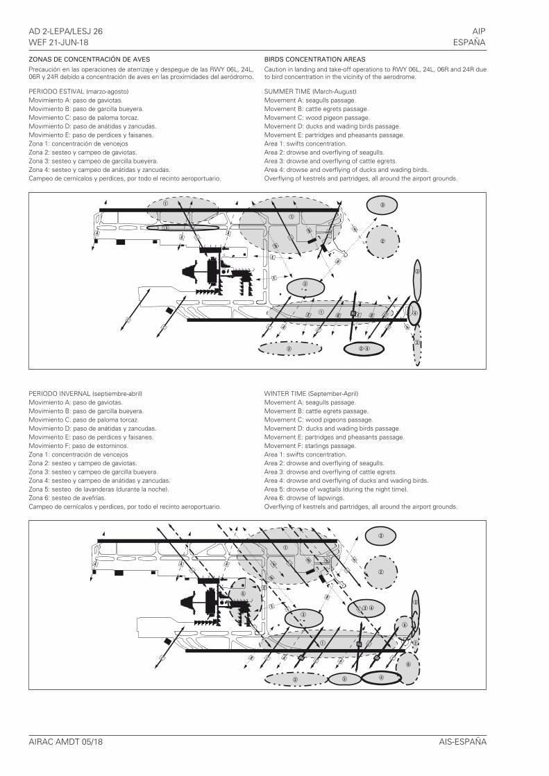
AD 2-LEPA/LESJ 26 AIPWEF 21-JUN-18 ESPAÑA
AIRAC AMDT 05/18 AIS-ESPAÑA
ZONAS DE CONCENTRACIÓN DE AVES
Precaución en las operaciones de aterrizaje y despegue de las RWY 06L, 24L,06R y 24R debido a concentración de aves en las proximidades del aeródromo.
PERIODO ESTIVAL (marzo-agosto)Movimiento A: paso de gaviotas.Movimiento B: paso de garcilla bueyera.Movimiento C: paso de paloma torcaz.Movimiento D: paso de anátidas y zancudas.Movimiento E: paso de perdices y faisanes.Zona 1: concentración de vencejosZona 2: sesteo y campeo de gaviotas.Zona 3: sesteo y campeo de garcilla bueyera.Zona 4: sesteo y campeo de anátidas y zancudas.Campeo de cernícalos y perdices, por todo el recinto aeroportuario.
PERIODO INVERNAL (septiembre-abril)Movimiento A: paso de gaviotas.Movimiento B: paso de garcilla bueyera.Movimiento C: paso de paloma torcaz.Movimiento D: paso de anátidas y zancudas.Movimiento E: paso de perdices y faisanes.Movimiento F: paso de estorninos.Zona 1: concentración de vencejosZona 2: sesteo y campeo de gaviotas.Zona 3: sesteo y campeo de garcilla bueyera.Zona 4: sesteo y campeo de anátidas y zancudas.Zona 5: sesteo de lavanderas (durante la noche).Zona 6: sesteo de avefrías.Campeo de cernícalos y perdices, por todo el recinto aeroportuario.
BIRDS CONCENTRATION AREAS
Caution in landing and take-off operations to RWY 06L, 24L, 06R and 24R dueto bird concentration in the vicinity of the aerodrome.
SUMMER TIME (March-August)Movement A: seagulls passage.Movement B: cattle egrets passage.Movement C: wood pigeon passage.Movement D: ducks and wading birds passage.Movement E: partridges and pheasants passage.Area 1: swifts concentration.Area 2: drowse and overflying of seagulls.Area 3: drowse and overflying of cattle egrets.Area 4: drowse and overflying of ducks and wading birds.Overflying of kestrels and partridges, all around the airport grounds.
WINTER TIME (September-April)Movement A: seagulls passage.Movement B: cattle egrets passage.Movement C: wood pigeons passage.Movement D: ducks and wading birds passage.Movement E: partridges and pheasants passage.Movement F: starlings passage.Area 1: swifts concentration.Area 2: drowse and overflying of seagulls.Area 3: drowse and overflying of cattle egrets.Area 4: drowse and overflying of ducks and wading birds.Area 5: drowse of wagtails (during the night time).Area 6: drowse of lapwings.Overflying of kestrels and partridges, all around the airport grounds.
AIP AD 2-LEPA/LESJ 27ESPAÑA WEF 21-JUN-18
AIS-ESPAÑA AIRAC AMDT 05/18
RECUBRIMIENTO CON ESPUMA DE PISTAS
No se presta el servicio de recubrimiento con espuma de las pistas comomedida de protección, en caso de aterrizaje de emergencia.
APANTALLAMIENTO DE LUCES DE APROXIMACIÓN
FOAM COVERING OF RUNWAYS
In case of emergency landing, foam covering service of runways as a safetymeasure is not provided.
SHIELDING OF APPROACH LIGHTS
ELEMENTO APANTALLADOSHIELDED ELEMENT RWY OBJETO QUE APANTALLA
SHIELDING OBJECTCONSECUENCIACONSECUENCE
Barra transversal situada a 450 m del umbral /Crossbar located at 450 m from threshold 06L Carretera / Road
Se pierde la referencia visual que supone la barratransversal situada a 450 m del umbral / The visualreference provided by the crossbar located at 450 mfrom threshold disappears.
2 luces centrales situadas a 480 m del umbral / 2central lights located at 480 m from threshold 06L Carretera / Road
La distancia entre las luces de la línea central pasaa ser de 81 m / The distance between the lights inthe central line will be 81 m.

INTENCIO
NADAMENTE E
N BLANCO
INTENTIO
NALLY B
LANK