Embed Size (px)
Citation preview
LED color indicator
86
90
26
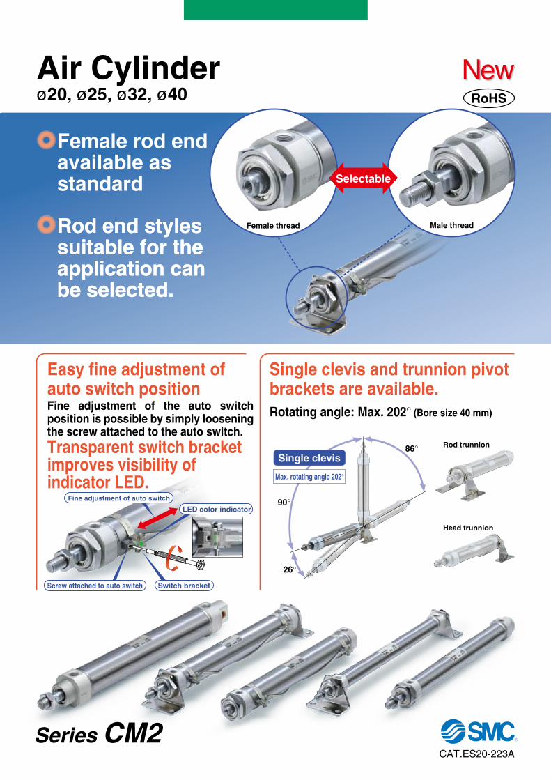
Single clevis
Max. rotating angle 202
Rod trunnion
Head trunnion
Rotating angle: Max. 202 (Bore size 40 mm)
Female rod end available as standard
Rod end styles suitable for the application can be selected.
Rod end styles suitable for the application can be selected.
Fine adjustment of the auto switch position is possible by simply loosening the screw attached to the auto switch.
Easy fine adjustment of auto switch position
Transparent switch bracket improves visibility of indicator LED.
Single clevis and trunnion pivotbrackets are available.
Fine adjustment of auto switch
Female thread Male thread
Selectable
Screw attached to auto switch Switch bracket
Air Cylinderø20, ø25, ø32, ø40
CAT.ES20-223A
Series CM2
NewNewRoHS
Boss-cut/Basic (BZ) Boss-cut/Rod flange (FZ) Boss-cut/Rod trunnion (UZ)
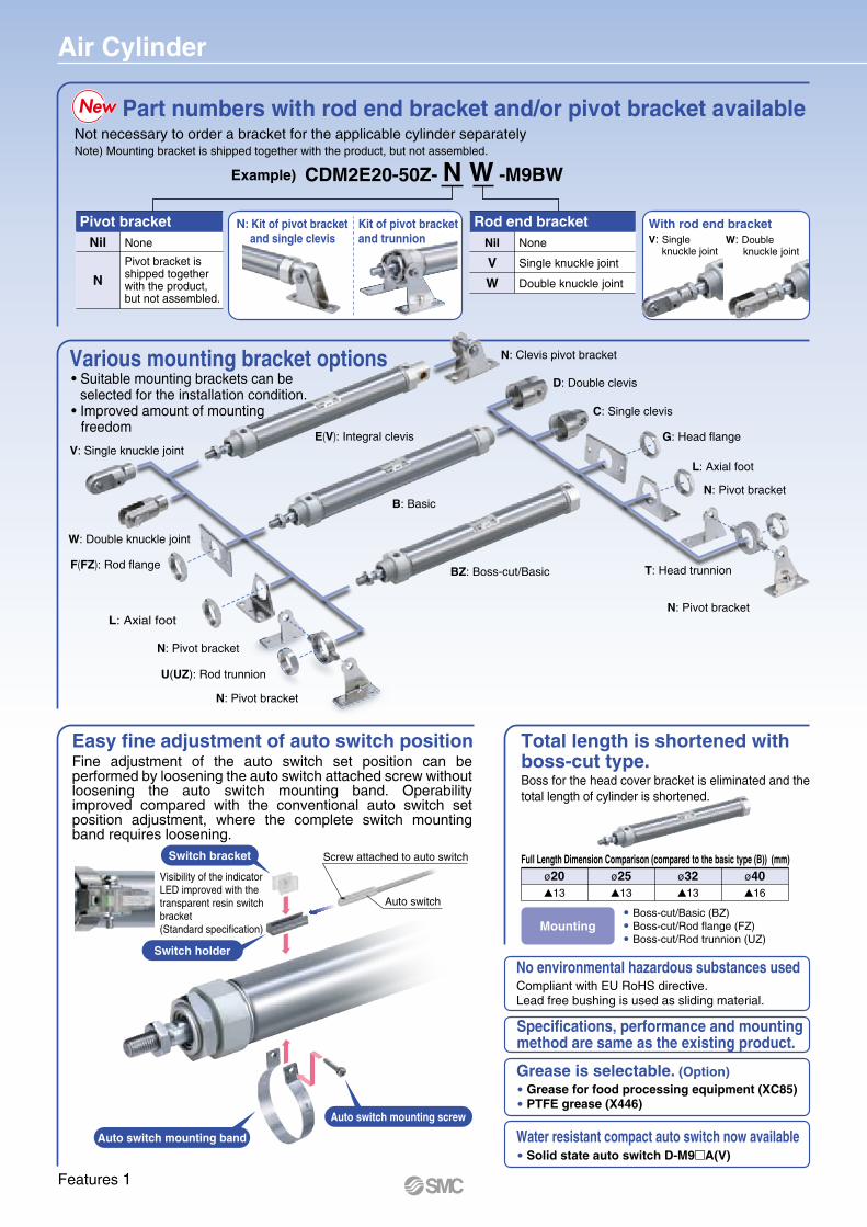
Boss for the head cover bracket is eliminated and the total length of cylinder is shortened.
Full Length Dimension Comparison (compared to the basic type (B)) (mm)ø20
13
ø2513
ø3213
ø4016
Air Cylinder
Compliant with EU RoHS directive. Lead free bushing is used as sliding material.
No environmental hazardous substances used
Grease for food processing equipment (XC85)PTFE grease (X446)
Grease is selectable. (Option)
Solid state auto switch D-M9 A(V)Water resistant compact auto switch now available
Specifications, performance and mounting method are same as the existing product.
Total length is shortened with boss-cut type.
Auto switch mounting band
Switch holder
Auto switch mounting screw
Switch bracket
Visibility of the indicator LED improved with the transparent resin switchbracket(Standard specification)
Auto switch
Screw attached to auto switch
Easy fine adjustment of auto switch position
Mounting
Part numbers with rod end bracket and/or pivot bracket available
With rod end bracketN: Kit of pivot bracket and single clevis
Kit of pivot bracket and trunnion
Not necessary to order a bracket for the applicable cylinder separatelyNote) Mounting bracket is shipped together with the product, but not assembled.
Example) CDM2E20-50Z- N W -M9BW
Pivot bracketNil None
Pivot bracket is shipped together with the product, but not assembled.
N
NewNew
Rod end bracketNil None
Single knuckle jointV
Double knuckle jointW
Various mounting bracket options• Suitable mounting brackets can be selected for the installation condition.• Improved amount of mounting freedom
V: Singleknuckle joint
W: Doubleknuckle joint
D: Double clevis
C: Single clevis
G: Head flange
F(FZ): Rod flange
L: Axial foot
L: Axial foot
T: Head trunnion
U(UZ): Rod trunnion
N: Pivot bracket
N: Pivot bracket
N: Pivot bracket
N: Pivot bracket
N: Clevis pivot bracket
B: Basic
E(V): Integral clevis
BZ: Boss-cut/Basic
V: Single knuckle joint
W: Double knuckle joint
Fine adjustment of the auto switch set position can be performed by loosening the auto switch attached screw without loosening the auto switch mounting band. Operability improved compared with the conventional auto switch set position adjustment, where the complete switch mounting band requires loosening.
Features 1
Page of this catalogPage 1
CAT.ES20-212
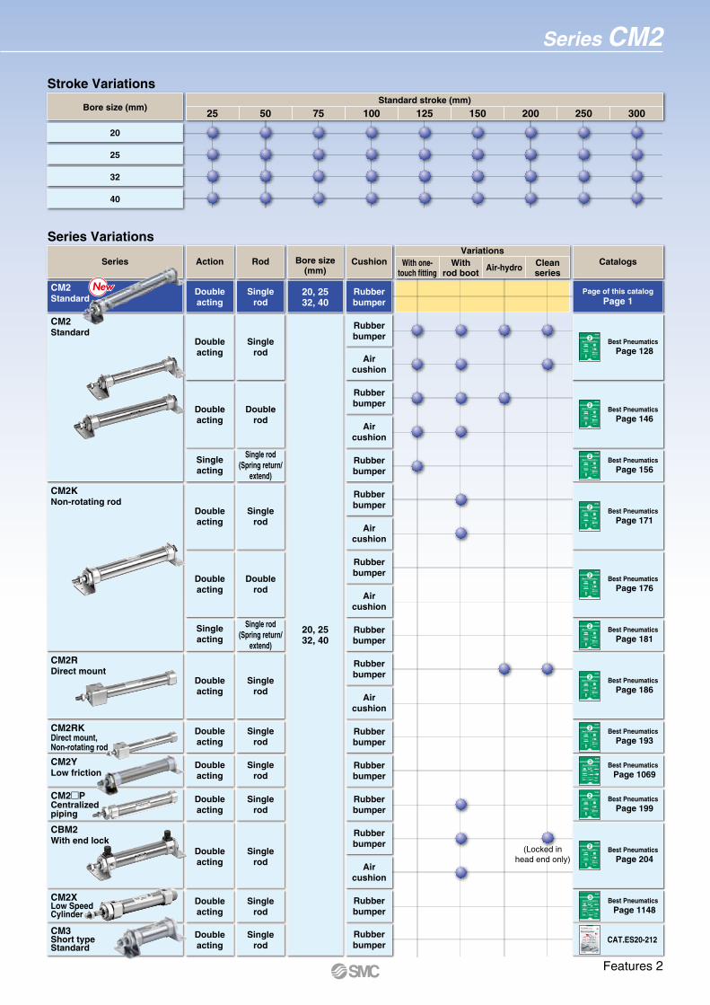
Series Variations
Withrod boot
Cleanseries
With one-touch fitting
Air-hydro
VariationsBore size
(mm)CushionSeries Action Rod Catalogs
Page 128Best Pneumatics
Page 146Best Pneumatics
Page 156Best Pneumatics
Page 171Best Pneumatics
Page 176Best Pneumatics
Page 181Best Pneumatics
Page 186Best Pneumatics
Page 193Best Pneumatics
Page 1069Best Pneumatics
Page 199Best Pneumatics
Page 204Best Pneumatics
Page 1148Best Pneumatics
Space saving; contributes to downsizing of equipment.
138 mm
CM3B40-50 stroke
Up toUp to
Up toUp to
shortershorter
Minimized with shorter total length!Minimized with shorter total length!
Air Cylinder Short Type
Compact with a new construction!New release with full functions
21%21%
66 mm66 mmlighterlighter
RoHS
CM3CM3
CM2
Female thread,Boss-cut
Male thread
Male thread
NEW
CM3CM3NEW
Conventional model
29 mm shorter
NewNew
Series CM3CAT.ES20-212A
Best Pneumatics22
Ver.1
Standard Air Cylinders Compact Air Cylinders
Floating Joints
Water Resistant Cylinders
Air-hydro Units
Rodless Cylinders
Auto Switches
Best Pneumatics22
Ver.1
Standard Air Cylinders Compact Air Cylinders
Floating Joints
Water Resistant Cylinders
Air-hydro Units
Rodless Cylinders
Auto Switches
Best Pneumatics22
Ver.1
Standard Air Cylinders Compact Air Cylinders
Floating Joints
Water Resistant Cylinders
Air-hydro Units
Rodless Cylinders
Auto Switches
Best Pneumatics22
Ver.1
Standard Air Cylinders Compact Air Cylinders
Floating Joints
Water Resistant Cylinders
Air-hydro Units
Rodless Cylinders
Auto Switches
Best Pneumatics22
Ver.1
Standard Air Cylinders Compact Air Cylinders
Floating Joints
Water Resistant Cylinders
Air-hydro Units
Rodless Cylinders
Auto Switches
Best Pneumatics22
Ver.1
Standard Air Cylinders Compact Air Cylinders
Floating Joints
Water Resistant Cylinders
Air-hydro Units
Rodless Cylinders
Auto Switches
Best Pneumatics22
Ver.1
Standard Air Cylinders Compact Air Cylinders
Floating Joints
Water Resistant Cylinders
Air-hydro Units
Rodless Cylinders
Auto Switches
Best Pneumatics22
Ver.1
Standard Air Cylinders Compact Air Cylinders
Floating Joints
Water Resistant Cylinders
Air-hydro Units
Rodless Cylinders
Auto Switches
Best Pneumatics33
Ver.1
Table Cylinders
Specialty Cylinders
Stroke Reading Cylinders
Guide Cylinders
Clamp Cylinders
Valve Mounted Cylinders
Lock Cylinders
Stopper Cylinders
Shock Absorbers
Auto Switches
Best Pneumatics22
Ver.1
Standard Air Cylinders Compact Air Cylinders
Floating Joints
Water Resistant Cylinders
Air-hydro Units
Rodless Cylinders
Auto Switches
Best Pneumatics22
Ver.1
Standard Air Cylinders Compact Air Cylinders
Floating Joints
Water Resistant Cylinders
Air-hydro Units
Rodless Cylinders
Auto Switches
Best Pneumatics33
Ver.1
Table Cylinders
Specialty Cylinders
Stroke Reading Cylinders
Guide Cylinders
Clamp Cylinders
Valve Mounted Cylinders
Lock Cylinders
Stopper Cylinders
Shock Absorbers
Auto Switches
75 100 125 150 200 250 30025 50Standard stroke (mm)
Bore size (mm)
20
25
32
40
CM2Standard
Doubleacting
Singlerod
Rubberbumper
Doubleacting
Singlerod
Doubleacting
Singlerod
Doubleacting
Doublerod
Singleacting
Single rod(Spring return/
extend)
Doubleacting
Singlerod
CM3Short typeStandard
CM2RKDirect mount, Non-rotating rod
CM2Standard
CM2KNon-rotating rod
20, 2532, 40
Rubberbumper
Rubberbumper
Aircushion
Rubberbumper
Aircushion
Rubberbumper
Doubleacting
Doublerod
Singleacting
Single rod(Spring return/
extend)
Rubberbumper
Aircushion
Rubberbumper
Rubberbumper
Aircushion
Doubleacting
Singlerod
Doubleacting
Singlerod
Doubleacting
Singlerod
CM2RDirect mount
CBM2With end lock
Rubberbumper
Aircushion
Doubleacting
Singlerod
CM2 PCentralizedpiping
Rubberbumper
Doubleacting
Singlerod
CM2XLow Speed Cylinder
Rubberbumper
Aircushion
Rubberbumper
Rubberbumper
CM2YLow friction
Doubleacting
Singlerod
Rubberbumper
20, 2532, 40
(Locked inhead end only)
NewNew
Stroke Variations
Series CM2
Features 2

How to Order
M9BWWith auto switch CDM2
CM2
Z
ZC VN
C
MountingBLFGCDT
UEV
BZFZUZ
BasicAxial foot
Rod flangeHead flangeSingle clevisDouble clevisHead trunnion
Rod trunnionIntegral clevis
Integral clevis (90 )Boss-cut/Basic
Boss-cut/Rod flangeBoss-cut/Rod trunnion
Auto switch
NilSn
2 pcs.1 pc.n pcs.
Number ofauto switches
Nil Without auto switch
Bore size20253240
20 mm25 mm32 mm40 mm
With auto switch(Built-in magnet)
20
20
Lead wire length symbols: 0.5 m…………… Nil (Example) M9NW 1 m…………… M (Example) M9NWM 3 m…………… L (Example) M9NWL 5 m…………… Z (Example) M9NWZNone…………… N (Example) H7CN
Solid state auto switches marked with “ ” are produced upon receipt of order.Do not indicate suffix “N” for no lead wire on the D-A3 A/A44A/G39A/K39A models.
Since there are other applicable auto switches than listed above, refer to page 17 for details.For details about auto switches with pre-wired connector, refer to pages 1328 and 1329 in Best Pneumatics No. 2.The D-A9 (V)/M9 (V)/M9 W(V)/M9 (V) auto switches are shipped together, (but not assembled). (However, only the auto switch mounting brackets are assembled before shipment.)
Bore size(mm)
20253240
Standard stroke (mm)Maximum stroke
(mm)
1000
25, 50, 75, 100, 125, 150, 200, 250, 30025, 50, 75, 100, 125, 150, 200, 250, 30025, 50, 75, 100, 125, 150, 200, 250, 30025, 50, 75, 100, 125, 150, 200, 250, 300
StrokeRefer to the table below for applicable strokes.
Water resistant type auto switches can be mounted on the above models, but in such case SMC cannot guarantee water resistance. A water-resistant type cylinder is recommended for use in an environment which requires water resistance.
Applicable Auto Switches/Refer to in pages 1263 to 1371 Best Pneumatic No. 2 for further information on auto switches.
5 V,12 V
12 V
5 V,12 V12 V
5 V,12 V
12 V
5 V,12 V
12 V5 V,12 V
5 V
12 V
12 V
—
NoNo
NoY
esY
esYe
sYe
sY
es
Type Special functionElectrical
entry
Grommet
Connector
Grommet
Grommet
Connector
DIN terminal
Terminalconduit
Grommet
Terminalconduit
—100 V
100 V or less100 V, 200 V200 V or less
—24 V or less
—
100 V, 200 V
—
Wiring(Output)
3-wire (NPN)3-wire (PNP)
2-wire
3-wire (NPN)2-wire
3-wire (NPN)3-wire (PNP)
2-wire3-wire (NPN)3-wire (PNP)
2-wire4-wire (NPN)
3-wire (NPN equivalent)
2-wire
Load voltage
DC
24 V
—
24 V
AC Perpendicular In-line
Lead wire length (m)
——
———
——
———
——
—
—
—
————
———
————————————
—
———
———————————
Applicable loadPre-wiredconnector
Auto switch model
IC circuit
—
IC circuit—
IC circuit
—
IC circuit
—IC circuitIC circuit
—IC circuit
—
IC circuit
—
Relay,PLC
Relay,PLC
Relay,PLCDiagnostic indication
(2-color indication)
Water resistant (2-color indication)
With diagnostic output (2-color indication)
Diagnostic indication (2-color indication)
M9NM9PM9BH7C
G39AK39AM9NWM9PWM9BW
M9NAM9PAM9BA
H7NFA96A93A90B54B64
C73CC80CA33AA34AA44AB59W
M9NVM9PVM9BV
———
M9NWVM9PWVM9BWV
M9NAVM9PAVM9BAV
—A96VA93VA90V
————————
—
PLC
—
0.5(Nil)
3(L)
——————
————————————
1(M)
5(Z)
None(N)
50
50
NilF
Male rod endFemale rod end
Rod end thread
Table (1) Applicable Strokes
NilVW
NoneSingle knuckle jointDouble knuckle joint
Rod end bracket
No bracket is provided for the female rod end type.
A knuckle joint pin is not provided with the single knuckle joint. Rod end bracket is shipped together with the product, but not assembled.
NilN
NonePivot bracket is shipped together
with the product, but not assembled.
Pivot bracket
Only for C, T, U, E, V, UZ mounting types.Pivot bracket is shipped together with the product, but not assembled.
Manufacture of intermediate strokes in 1 mm intervals is possible.
N
For details, refer to the next page.
For applicable auto switches, refer to the table below.
RoHS
V
Indica
tor lig
ht
So
lid s
tate
au
to s
wit
chR
eed
au
to s
wit
ch
Made to Order
1
Air Cylinder Standard: Double Acting, Single Rod
ø20, ø25, ø32, ø40Series CM2

20 25 32 40
0.27 J
0.11 J
0.4 J
0.18 J
0.65 J
0.29 J
1.2 J
0.52 J
+1.4 0 mm
Bore size(mm)
Standard stroke (mm) Maximum stroke(mm)
20253240
25, 50, 75, 100, 125, 150, 200, 250, 300 1000
Note) Intermediate strokes not listed above are produced upon receipt of order. Manufacture of intermediate strokes in 1 mm intervals is possible. (Spacers are not used.)
Operate the cylinder with in the allowable kinetic energy.
Bore size (mm)
• Auto switch proper mounting position (detection at stroke end) and its mounting height
• Minimum stroke for auto switch mounting• Operating range• Auto switch mounting brackets/Part no.
Refer to pages 14 to 17 for cylinders with auto switches
Specifications
Standard Strokes
JIS Symbol
Double acting, Single rod
Type
Action
Fluid
Proof pressure
Maximum operating pressure
Minimum operating pressure
Ambient and fluid temperature
Lubrication
Stroke length tolerance
Piston speed
Cushion
Allowablekinetic energy
Pneumatic
Double acting, Single rod
Air
1.5 MPa
1.0 MPa
0.05 MPa
Not required (Non-lube)
50 to 750 mm/s
Rubber bumper
Without auto switch: −10 C to 70 C(No freezing)
With auto switch: −10 C to 60 C
(Male thread)(Female thread)
Made toOrder Made to Order
(For details, refer to pages 19 to 20.)
Symbol SpecificationsSpecial port locationHead cover axial portMounting nut with set screwGrease for food processing equipmentPTFE grease
-XC3-XC20-XC52-XC85-X446
Warning1. Operate the cylinder within the specified cylinder speed, kinetic
energy and lateral load at the rod end.
2. The allowable kinetic energy is different between the cylinders with male rod end and with female rod end due to the different thread sizes.
3. When female rod end is used, use a washer etc. to prevent the contact part at the rod end from being deformed depending on the material of the work piece.
4. Do not apply excessive lateral load to the piston rod.Easy checking method
Minimum operating pressure after the cylinder is mounted to the equipment (MPa) = Minimum operating pressure of cylinder (MPa) + {Load weight (kg) x Friction coefficient of guide/Sectional area of cylinder (mm2)}If smooth operation is confirmed within the above value, the load on the cylinder is the resistance of the thrust only and it can be judged as having no lateral load.
Caution1. When rod end female thread is used, use a thin wrench when tightening
the piston rod.
Ordering Example of Cylinder Assembly
Cylinder model: CDM2C20-50Z-NV-M9BW
Single knuckle joint
Single clevis
Auto switch
Pivot bracket
Pivot bracket, double knuckle joint and auto switch are shipped together with the product, but not assembled.
Mounting C: Single clevisPivot bracket N: YesRod end bracket V: Single knuckle jointAuto switch D-M9BW: 2 pcs.
Note)
2
Series CM2Air Cylinder
Standard: Double Acting, Single Rod

Accessories
Mounting
Basic (Double-side bossed)
Axial foot
Rod flange
Head flange
Single clevis
Double clevis
Rod trunnion
Head trunnion
Integral clevis
Integral clevis (90 )
Boss-cut/Basic
BLFGCDUTEV
BZ
FZ
UZ
(1 pc.)
(1 pc.)
(1 pc.)
(1 pc.)
(1 pc.)
(1 pc.)
(1 pc.)
(1 pc.)
(1 pc.)
(1 pc.)
(1 pc.)
(1 pc.)
(1 pc.)
(1 pc.)
(1 pc.)
(1 pc.)
(1 pc.)
(1 pc.)
(1 pc.)
(1 pc.)
(1 pc.)
(1 pc.) (1 pc.)(2 pc.)
(2 pc.)
(1 pc.)
(1 pc.)
(1 pc.)
(1 pc.)
(1 pc.) (1 pc.)
(1 pc.)
(1 pc.)Note 2)
(1 pc.)
(1 pc.)Note 3)
Note 3)
Note 4)
Note 4)
Note 3)
Note 3)
(1 pc.)
(1 pc.)
Note 4)
Note 3)
Note 4)
Note 3)
Note 3)
Note 3)
Note 3)
Note 3)
Note 3)
(1 pc.)
(1 pc.)
(1 pc.)
(1 pc.)
(1 pc.)
(1 pc.)
(1 pc.)
(1 pc.)
(1 pc.)
(1 pc.)
(1 pc.)
(1 pc.)
(1 pc.)
(1 pc.)
Standard (mounted to the body) Standard (packaged together, but not assembled)
Standard (mounted to the body) Option
Option
Rod
end
nut
(Mal
e th
read
)
Mou
ntin
g nu
t
Bod
y
(1 pc.)
Sin
gle
clev
is(Max. 3 pcs.)
(Max. 3 pcs.)
Line
r
Dou
ble
clev
is
(1 pc.)Note 2)
Note 3)
Note 3)
Note 3)
Note 3)
(2 pc.)
(1 pc.)
(1 pc.)
(1 pc.)
Mou
ntin
gnu
t
Foo
t
Fla
nge
Piv
otbr
acke
t
Piv
otbr
acke
t pin
(1 pc.)
Dou
ble
clev
is p
in
(1 pc.)
(1 pc.)
(1 pc.)
Trun
nion
(1 pc.)
(1 pc.)
(1 pc.)
Mou
ntin
g nu
t(F
or T
runn
ion)
Cle
vis
pivo
tbr
acke
t(C
M2E
/CM
2V)
Cle
vis
pivo
tbr
acke
t pin
(CM
2E/C
M2V
)
Sing
le kn
uckle
joint
(M
ale th
read o
nly)
Doub
le kn
uckle
joint
(Male
threa
d only
)
Not
e 6)
Note 5
)
Not
e 5)
Not
e 5)
Not
e 7)
Not
e 1)
Mounting and Accessories
Mounting bracket Contents (for minimum order quantity)Min.orderqty.
Bore size (mm)
FootFlangeSingle clevis
Double clevis (with pin)
Trunnion (with nut)Rod end nutMounting nutTrunnion nutSingle knuckle joint
Double knuckle joint
Clevis pin (Double clevis)
Clevis pin(Double knuckle joint)
Pivot bracket pinClevis pivot bracket pin (For CM2E/CM2V)
Clevis pivot bracket (For CM2E/CM2V)
Pivot bracket (For CM2C)
Pivot bracket (For CM2U/CM2T)
211
1
11111
1
1
1
11111
20
Order 2 foots per cylinder.3 liners are included with a clevis bracket for adjusting the mounting angle. A clevis pin and retaining rings (split pins for ø40) are included.
CM-L020BCM-F020BCM-C020B
CM-D020B
CM-T020BNT-02
SN-020BTN-020BI-020B
Y-020B
CM-B020
25CM-L032BCM-F032BCM-C032B
CM-D032B
CM-T032BNT-03
SN-032BTN-032BI-032B
Y-032B
CM-B032
32
CD-S03CM-E032B
40CM-L040BCM-F040BCM-C040B
CM-D040B
CM-T040BNT-04
SN-040BTN-040BI-040B
Y-040B
CDP-2
CM-B040CM-B040
2 foots, 1 mounting nut1 flange1 single clevis, 3 liners
1 trunnion, 1 trunnion nut1 rod end nut1 mounting nut1 trunnion nut1 single knuckle joint1 double knuckle joint,1 clevis pin, 2 retaining rings
1 clevis pin, 2 retaining rings1 clevis pivot bracket, 1 clevis pin, 2 retaining rings2 pivot brackets (1 of each type)2 pivot brackets (1 of each type)
Mounting Brackets/Part No.
Single clevis + Pivot bracket + Pin
Mounting: CPivot bracket symbol: N
Trunnion + Pivot bracket
Mounting: T, U, UZPivot bracket symbol: N
Integral clevis + Pivot bracket + Pin
Mounting: EPivot bracket symbol: N
Integral clevis (90°) + Pivot bracket + Pin
Mounting: VPivot bracket symbol: N
Boss-cut/Rod trunnion
Boss-cut/Rod flange
1 clevis pin, 2 retaining rings (split pins)
1 clevis pin, 2 retaining rings (split pins)
1 pin, 2 retaining rings
1 double clevis, 3 liners,1 clevis pin, 2 retaining rings
CM-B032
CDP-1
CDP-1 CDP-3
CD-S03
CDP-1
CD-S02CM-E020B
(Max. 3 pcs.)
Note 1) Rod end nut is not provided for the female rod end type.Note 2) Two mounting nuts are packaged together.Note 3) Mounting nut is not packaged for the clevis type. Note 4) Trunnion nut is packaged for U, T, UZ.
Note 5) Retaining rings are included.Note 6) A pin and retaining rings (split pins for ø40) are included.Note 7) This is the part(s) used to adjust the clevis angle. Mounting quantity can vary.
3
Series CM2
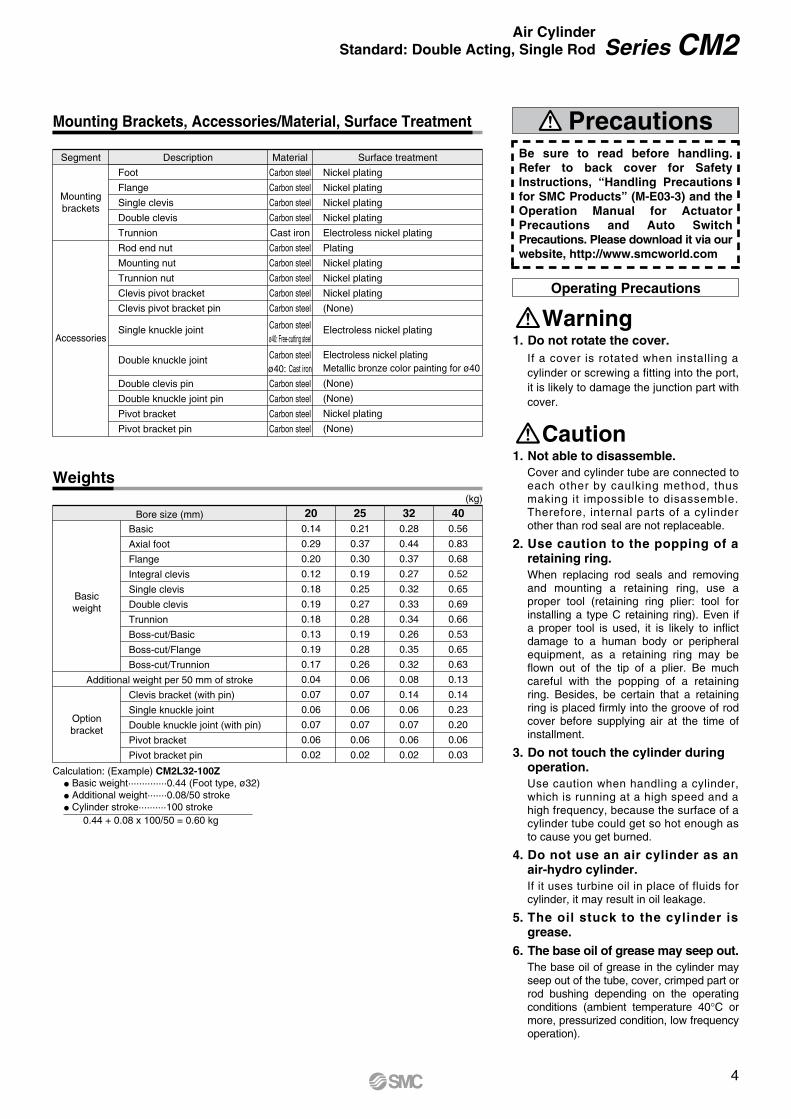
Calculation: (Example) CM2L32-100ZBasic weight··············0.44 (Foot type, ø32)Additional weight·······0.08/50 strokeCylinder stroke··········100 stroke
0.44 + 0.08 x 100/50 = 0.60 kg
Description Material Surface treatmentSegment
Mountingbrackets
Accessories
Foot
Flange
Single clevis
Double clevis
Trunnion
Rod end nut
Mounting nut
Trunnion nut
Clevis pivot bracket
Clevis pivot bracket pin
Single knuckle joint
Double knuckle joint
Double clevis pin
Double knuckle joint pin
Pivot bracket
Pivot bracket pin
Carbon steel
Carbon steel
Carbon steel
Carbon steel
Cast iron
Carbon steel
Carbon steel
Carbon steel
Carbon steel
Carbon steel
Carbon steel
Carbon steel
Carbon steel
Carbon steel
Carbon steelø40: Free-cutting steel
Carbon steelø40: Cast iron
Bore size (mm)
(kg)
Basicweight
Optionbracket
Basic
Axial foot
Flange
Integral clevis
Single clevis
Double clevis
Trunnion
Boss-cut/Basic
Boss-cut/Flange
Boss-cut/Trunnion
Clevis bracket (with pin)
Single knuckle joint
Double knuckle joint (with pin)
Pivot bracket
Pivot bracket pin
Additional weight per 50 mm of stroke
200.14
0.29
0.20
0.12
0.18
0.19
0.18
0.13
0.19
0.17
0.04
0.07
0.06
0.07
0.06
0.02
250.21
0.37
0.30
0.19
0.25
0.27
0.28
0.19
0.28
0.26
0.06
0.07
0.06
0.07
0.06
0.02
320.28
0.44
0.37
0.27
0.32
0.33
0.34
0.26
0.35
0.32
0.08
0.14
0.06
0.07
0.06
0.02
400.56
0.83
0.68
0.52
0.65
0.69
0.66
0.53
0.65
0.63
0.13
0.14
0.23
0.20
0.06
0.03
Precautions
Operating Precautions
1. Do not rotate the cover.If a cover is rotated when installing a cylinder or screwing a fitting into the port, it is likely to damage the junction part with cover.
1. Not able to disassemble.Cover and cylinder tube are connected to each other by caulking method, thus making it impossible to disassemble. Therefore, internal parts of a cylinder other than rod seal are not replaceable.
2. Use caution to the popping of a retaining ring.When replacing rod seals and removing and mounting a retaining ring, use a proper tool (retaining ring plier: tool for installing a type C retaining ring). Even if a proper tool is used, it is likely to inflict damage to a human body or peripheral equipment, as a retaining ring may be flown out of the tip of a plier. Be much careful with the popping of a retaining ring. Besides, be certain that a retaining ring is placed firmly into the groove of rod cover before supplying air at the time of installment.
3. Do not touch the cylinder duringoperation.Use caution when handling a cylinder, which is running at a high speed and a high frequency, because the surface of a cylinder tube could get so hot enough as to cause you get burned.
4. Do not use an air cylinder as an air-hydro cylinder.If it uses turbine oil in place of fluids for cylinder, it may result in oil leakage.
5. The oil stuck to the cylinder is grease.
6. The base oil of grease may seep out.The base oil of grease in the cylinder may seep out of the tube, cover, crimped part or rod bushing depending on the operating conditions (ambient temperature 40 C or more, pressurized condition, low frequency operation).
Be sure to read before handling. Refer to back cover for Safety Instructions, “Handling Precautions for SMC Products” (M-E03-3) and the Operation Manual for Actuator Precautions and Auto Switch Precautions. Please download it via ourwebsite, http://www.smcworld.com
Mounting Brackets, Accessories/Material, Surface Treatment
Weights
Caution
Warning
Nickel plating
Nickel plating
Nickel plating
Nickel plating
Electroless nickel plating
Plating
Nickel plating
Nickel plating
Nickel plating
(None)
Electroless nickel plating
Electroless nickel platingMetallic bronze color painting for ø40
(None)
(None)
Nickel plating
(None)
4
Series CM2Air Cylinder
Standard: Double Acting, Single Rod

Construction
No.
1
2A
2B
2C
3
4
5
6
7
8
9
10
11
12
13
14
15
16
17
Material
Aluminum alloy
Aluminum alloy
Aluminum alloy
Aluminum alloy
Stainless steel
Aluminum alloy
Carbon steel
Bearing alloy
Stainless steel
Carbon steel
Resin
Resin
NBR
NBR
Resin
Bearing alloy
Carbon steel
Carbon steel—
Note
Anodized
Anodized
Anodized
Anodized
Hard chrome plating
Phosphate coating
Nickel plating
Plating
CDM2 20 to 40- Z
Component Parts
No.
11
Description
Rod seal
Material
NBR
20CM20Z-PS
25CM25Z-PS
32CM32Z-PS
40CM40Z-PS
Part no.
Replacement Parts/Seal Kit
Since the seal kit does not include a grease pack, order it separately.Grease pack part number: GR-S-010 (10 g)
q o e r !2 !7 !3 !0 @A @B @C !4y!1
!6 !5
uit
Boss-cut Integral clevis
Description
Rod cover
Head cover A
Head cover B
Head cover C
Cylinder tube
Piston
Piston rod
Bushing
Seal retainer
Retaining ring
Bumper A
Bumper B
Rod seal
Piston seal
Wear ring
Clevis bushing
Mounting nut
Rod end nut
Plastic magnet
5
Series CM2

ø
2 × Rc P2 × NN(Effective thread length 2 x FL)
4 × øLD
HK F G
H2
H1
AAL
MM
ZXY
øD
LT
NAS + Stroke
LS + StrokeZZ + Stroke
X Y
G F
ø
NA
NA
I
ZZ + Stroke
2 × øLC BL
H
LZLX
H
øD
2 x Rc P
2 x
øE
h8
2 x NN
Effective thread length2 x FLWidth across flats KA
GG
MM ALA
HK F
FS + StrokeZZ + Stroke
H2
H1Width across flats B1
Width across flats B2
Width across flats B1
Width across flats KA
Width across flatsWidth across flats B2
Basic (B)
CM2B
Axial Foot (L)
CM2L
ZBore size Stroke
Boss-cutFemale rod end
Bore size
20253240
20253240
A18
22
22
24
AL15.5
19.5
19.5
21
B1
13
17
17
22
B2
26
32
32
41
D 8
10
12
14
F13
13
13
16
FL10.5
10.5
10.5
13.5
G 8
8
8
11
H41
45
45
50
H1
5
6
6
8
H2
8
8
8
10
I28
33.5
37.5
46.5
K5
5.5
5.5
7
KA 6
8
10
12
MMM8 x 1.25
M10 x 1.25
M10 x 1.25
M14 x 1.5
NA24
30
34.5
42.5
(mm)
Bore size NNM20 x 1.5
M26 x 1.5
M26 x 1.5
M32 x 2
P1/8
1/8
1/8
1/4
S62
62
64
88
ZZ116
120
122
154
(mm)
20253240
Bore size MMM8 x 1.25
M10 x 1.25
M10 x 1.25
M14 x 1.5
LZ55
55
55
75
LX40
40
40
55
NA24
30
34.5
42.5
NNM20 x 1.5
M26 x 1.5
M26 x 1.5
M32 x 2
P1/8
1/8
1/8
1/4
S62
62
64
88
X20
20
20
23
Y 8
8
8
10
Z21
25
25
27
ZZ131
135
137
171
(mm)
20253240
Bore size
103
107
109
138
ZZ(mm)Boss-cut
20253240
Bore size
8
8
12
13
A1
20
20
20
21
HM4 x 0.7
M5 x 0.8
M6 x 1
M8 x 1.25
MM 95
95
97
125
ZZ(mm)Female Rod End
E20
26
26
32
0−0.033
0−0.033
0−0.033
0−0.039
Bore size
20253240
A18
22
22
24
AL15.5
19.5
19.5
21
B40
47
47
54
B1
13
17
17
22
B2
26
32
32
41
D 8
10
12
14
F13
13
13
16
FL10.5
10.5
10.5
13.5
G 8
8
8
11
H41
45
45
50
H1
5
6
6
8
H2
8
8
8
10
I28
33.5
37.5
46.5
K5
5.5
5.5
7
KA 6
8
10
12
LC4
4
4
4
LD6.8
6.8
6.8
7
LH25
28
28
30
LS102
102
104
134
LT3.2
3.2
3.2
3.2
(mm)
ZBore size Stroke
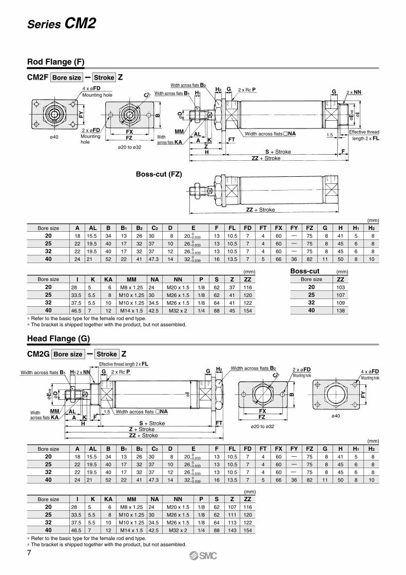
Refer to the basic type for the female rod end type.
The bracket is shipped together with the product, but not assembled.
When female thread is used, use a thin wrench when tightening the piston rod.
When female thread is used, use a washer, etc. to prevent the contact part at the rod end from being deformed depending on the material of the work piece.
ZZ + StrokeH
Depth A1
Female thread MM
6
Series CM2Air Cylinder
Standard: Double Acting, Single Rod
øø
2 x Rc P 2 x NN
Effective threadlength 2 x FL
1.5
øD
MM
AAL
ZH
K FT
GH2H1
NA
F
G
EI
Width across flats
4 x øFD2 x øFD
FXFZ
C2
B FY
ø
Widthacross flats KA
2 x Rc P2 x NNH1
MM
øDE
ALA K F
H
NA
GG H2
FT
øI
2 x øFD FXFZ
FY B
C2
ZZ + Stroke
ZZ + StrokeS + Stroke
Width across flats B1
Width across flats B2
Mounting hole
Mountinghole
ø40
ø20 to ø32
Widthacross flats KA
Width across flats B1Width across flats B2
S + StrokeZ + StrokeZZ + Stroke
ø20 to ø32
ø40
Mounting holeMounting hole
Width across flats
Effective thread length 2 x FL
Rod Flange (F)
CM2F
Boss-cut (FZ)
4 x øFD
Bore size
20253240
Bore size
20253240
A18
22
22
24
AL15.5
19.5
19.5
21
B34
40
40
52
B1
13
17
17
22
B2
26
32
32
41
C2
30
37
37
47.3
D 8
10
12
14
E F13
13
13
16
FL10.5
10.5
10.5
13.5
FD7
7
7
7
FT4
4
4
5
FX60
60
60
66
FY—
—
—
36
FZ75
75
75
82
G 8
8
8
11
H41
45
45
50
H1
5
6
6
8
H2
8
8
8
10
K5
5.5
5.5
7
MMM8 x 1.25
M10 x 1.25
M10 x 1.25
M14 x 1.5
NA24
30
34.5
42.5
NNM20 x 1.5
M26 x 1.5
M26 x 1.5
M32 x 2
P1/8
1/8
1/8
1/4
S62
62
64
88
Z107
111
113
143
ZZ116
120
122
154
(mm)
20
26
26
32
0−0.033
0−0.0330
−0.0330
−0.039
I28
33.5
37.5
46.5
KA 6
8
10
12
(mm)
Head Flange (G)
CM2G
Bore size
20253240
20253240
A18
22
22
24
AL15.5
19.5
19.5
21
B34
40
40
52
B1
13
17
17
22
B2
26
32
32
41
C2
30
37
37
47.3
D 8
10
12
14
F13
13
13
16
FL10.5
10.5
10.5
13.5
FD7
7
7
7
FT4
4
4
5
FX60
60
60
66
FY—
—
—
36
FZ75
75
75
82
G 8
8
8
11
H41
45
45
50
H1
5
6
6
8
H2
8
8
8
10
(mm)
Bore size KA 6
8
10
12
K5
5.5
5.5
7
I28
33.5
37.5
46.5
MMM8 x 1.25
M10 x 1.25
M10 x 1.25
M14 x 1.5
NA24
30
34.5
42.5
NNM20 x 1.5
M26 x 1.5
M26 x 1.5
M32 x 2
P1/8
1/8
1/8
1/4
S62
62
64
88
Z37
41
41
45
ZZ116
120
122
154
(mm)
20253240
Bore size
103
107
109
138
ZZ(mm)Boss-cut
E20
26
26
32
0−0.0330
−0.0330
−0.0330
−0.039
Refer to the basic type for the female rod end type. The bracket is shipped together with the product, but not assembled.
Refer to the basic type for the female rod end type. The bracket is shipped together with the product, but not assembled.
ZBore size Stroke
ZBore size Stroke
7
Series CM2
NA
NACX
øI
ø
ø
Width across flats KA
2 x Rc PNNEffective thread length FL
MM
H1Width across flats B1 G
ALA K F
H
E øD
G
UL
RR
CD
øC
I
NA
NA
CL
CZCX
øI−0.040−0.076
+0.0580
ø
Width across flats KA
2 x Rc PNN
Effective thread length FL
MM
H1Width across flats B1
E øD
ALA K
H
F
G G
øCD hole H10
Axis d9
LRR
øC
I
U
S + StrokeZ + Stroke+1.2
0
ZZ + Stroke+1.20
H10+0.058
0
−0.1−0.2
S + StrokeZ + Stroke+1.2
0
ZZ + Stroke+1.20
+0.2+0.1
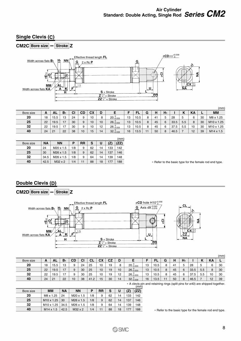
Single Clevis (C)
Double Clevis (D)
CM2C ZBore size Stroke
A clevis pin and retaining rings (split pins for ø40) are shipped together.
Bore size
20253240
Bore size
20253240
A18
22
22
24
AL15.5
19.5
19.5
21
B1
13
17
17
22
CD 9
9
9
10
CI24
30
30
38
CL25
25
25
41.2
CX10
10
10
15
CZ19
19
19
30
D 8
10
12
14
F13
13
13
16
FL10.5
10.5
10.5
13.5
G 8
8
8
11
H41
45
45
50
H1
5
6
6
8
I28
33.5
37.5
46.5
K5
5.5
5.5
7
KA 6
8
10
12
L30
30
30
39
NNM20 x 1.5
M26 x 1.5
M26 x 1.5
M32 x 2
P1/8
1/8
1/8
1/4
U14
14
14
18
(Z)133
137
139
177
(ZZ)142
146
148
188
(mm)
MMM8 x 1.25
M10 x 1.25
M10 x 1.25
M14 x 1.5
NA24
30
34.5
42.5
S62
62
64
88
RR 9
9
9
11
(mm)
E20
26
26
32
0−0.033
0−0.033
0−0.033
0−0.039
Bore size
20253240
Bore size
20253240
A18
22
22
24
AL15.5
19.5
19.5
21
B1
13
17
17
22
CI24
30
30
38
CD 9
9
9
10
CX10
10
10
15
D 8
10
12
14
FL10.5
10.5
10.5
13.5
F13
13
13
16
G 8
8
8
11
H41
45
45
50
H1
5
6
6
8
I28
33.5
37.5
46.5
K5
5.5
5.5
7
KA 6
8
10
12
L30
30
30
39
NNM20 x 1.5
M26 x 1.5
M26 x 1.5
M32 x 2
P1/8
1/8
1/8
1/4
U14
14
14
18
(Z)133
137
139
177
(ZZ)142
146
148
188
(mm)
MMM8 x 1.25
M10 x 1.25
M10 x 1.25
M14 x 1.5
NA24
30
34.5
42.5
S62
62
64
88
RR 9
9
9
11
(mm)
E20
26
26
32
0−0.033
0−0.033
0−0.033
0−0.039
Refer to the basic type for the female rod end type.
CM2D ZBore size Stroke
Refer to the basic type for the female rod end type.
8
Series CM2Air Cylinder
Standard: Double Acting, Single Rod

TZTX
øT
DøT
Y
TXTZ
øT
DøT
Y
2 x Rc P 2 x NN
Width across flats KAEffective thread length
2 x FL
øD
MM ALA K TT
ZH
H1Width across
flats B1
Width across flats B2G
Width across flats NA
S + StrokeZZ + Stroke
ZZ + Stroke
G
F
øE ø
I
øI
Width across flats KA
2 x Rc P2 x NNEffective thread length 2 x FL
MM
H1Width across flats B1
øE øD
ALA
HK F
G
Width across flats NA
S + StrokeZ + StrokeZZ + Stroke
G Width across flats B2
TT
−0.
025
e9−
0.06
1
−0.
025
e9−
0.06
1
Rod Trunnion (U)
Head Trunnion (T)
Boss-cut
Bore size
20253240
Bore size
20253240
A18
22
22
24
AL15.5
19.5
19.5
21
B1
13
17
17
22
B2
26
32
32
41
D 8
10
12
14
F13
13
13
16
FL10.5
10.5
10.5
13.5
G 8
8
8
11
H41
45
45
50
H1
5
6
6
8
I28
33.5
37.5
46.5
K5
5.5
5.5
7
KA 6
8
10
12
MMM8 x 1.25
M10 x 1.25
M10 x 1.25
M14 x 1.5
NA24
30
34.5
42.5
TX32
40
40
53
Z36
40
40
44.5
ZZ116
120
122
154
(mm)
NNM20 x 1.5
M26 x 1.5
M26 x 1.5
M32 x 2
P1/8
1/8
1/8
1/4
S62
62
64
88
TT10
10
10
11
TD 8
9
9
10
TZ52
60
60
77
TY32
40
40
53
(mm)
20253240
Bore size
103
107
109
138
ZZ(mm)Boss-cut
E20
26
26
32
0−0.033
0−0.033
0−0.033
0−0.039
Bore size
20253240
Bore size
20253240
A18
22
22
24
AL15.5
19.5
19.5
21
B1
13
17
17
22
B2
26
32
32
41
D 8
10
12
14
F13
13
13
16
FL10.5
10.5
10.5
13.5
G 8
8
8
11
H41
45
45
50
H1
5
6
6
8
I28
33.5
37.5
46.5
K5
5.5
5.5
7
KA 6
8
10
12
MMM8 x 1.25
M10 x 1.25
M10 x 1.25
M14 x 1.5
NA24
30
34.5
42.5
TX32
40
40
53
Z108
112
114
143.5
ZZ118
122
124
154
(mm)
NNM20 x 1.5
M26 x 1.5
M26 x 1.5
M32 x 2
P1/8
1/8
1/8
1/4
S62
62
64
88
TT10
10
10
11
TD 8
9
9
10
TZ52
60
60
77
TY32
40
40
53
(mm)
E20
26
26
32
0−0.033
0−0.033
0−0.033
0−0.039
CM2U ZBore size Stroke
The bracket is shipped together with the product, but not assembled.
The bracket is shipped together with the product, but not assembled.
CM2T ZBore size Stroke
9
Series CM2

Width across flats KA
2 x Rc P
Effective thread length FL
NA
2 x øLDMMNNWidth across flats B1
øD
øE
G
HFKA
ALH1
LPL
GU
RR
øCD
øC
I
LF LGLYL
T
NA
LH
LV
CX
øI
Refer to page 12 for detailson pivot clevis bracket.
LZ + StrokeZZ + StrokeZ + StrokeS + Stroke
H10+0.0580 −0
−0.1
Integral Clevis (E)
Integral Clevis (90 ) (V)
Bore size
20253240
Bore size
20253240
A18
22
22
24
AL15.5
19.5
19.5
21
B1
13
17
17
22
CD 8
8
10
10
CI20
22
27
33
CX12
12
20
20
D 8
10
12
14
F13
13
13
16
FL10.5
10.5
10.5
13.5
G 8
8
8
11
H41
45
45
50
H1
5
6
6
8
I28
33.5
37.5
46.5
MMM8 x 1.25
M10 x 1.25
M10 x 1.25
M14 x 1.5
L12
12
15
15
KA 6
8
10
12
K5
5.5
5.5
7
Z115
119
124
153
(mm)
NNM20 x 1.5
M26 x 1.5
M26 x 1.5
M32 x 2
P1/8
1/8
1/8
1/4
NA24
30
34.5
42.5
RR 9
9
12
12
U11.5
11.5
14.5
14.5
S62
62
64
88
ZZ124
128
136
165
(mm)
E20
26
26
32
0−0.033
0−0.033
0−0.033
0−0.039
(mm)
Bore size
20253240
LD6.8
6.8
9
9
LF15
15
15
15
LG30
30
40
40
LH30
30
40
40
LP37
37
50
50
LT3.2
3.2
4
4
LV18.4
18.4
28
28
LY59
59
75
75
LZ152
156
174
203
Clevis Pivot Bracket
Port
Refer to the basic type for the female rod end type.
The outer dimensions are the same as those for the integral clevis (E) type.
CM2E ZBore size Stroke
10
Series CM2Air Cylinder
Standard: Double Acting, Single Rod

Series CM2Dimensions of Accessories 1
With Single Knuckle Joint (mm) Single Knuckle Joint (mm)
Double Clevis Pin/Material: Carbon steel (mm) Double Knuckle Pin/Material: Carbon steel (mm)
I-020B/032B Material: Carbon steel I-040B Material: Free-cutting steel Y (MAX)
(MIN)
Bore size
2025, 32
40
A18
22
24
H41
45
50
MMM8 x 1.25
M10 x 1.25
M14 x 1.5
9
9
12
+0.0580
+0.0580
+0.0700
NX1−0.1−0.2
−0.1−0.2
−0.1−0.3
9
9
16
U1
14
14
20
R2
10
10
14
Y11
14
13
Z66
69
92
NDH10
With Double Knuckle Joint (mm)
Double Knuckle Joint (mm)
U1
14
14
20
Part no.
I-020BI-032BI-040B
Applicablebore size
2025, 32
40
A46
48
69
A1
16
18
22
E1
20
20
24
LB36
38
55
MMM8 x 1.25
M10 x 1.25
M14 x 1.5
9
9
12
+0.0580
+0.0580
+0.0700
NX−0.1−0.2
−0.1−0.2
−0.1−0.3
9
9
16
NDH10 R1
10
10
15.5
Y (MAX)
Bore size
2025, 32
40
A18
22
24
H41
45
50
L25
25
49.7
MMM8 x 1.25
M10 x 1.25
M14 x 1.5
NX2+0.2+0.1
+0.2+0.1
+0.3+0.1
9
9
16
R2
10
10
13
U2
14
14
25
Y11
14
13
Z66
69
92
ND 9
9
12
Y-020B/032B Material: Carbon steel Y-040B Material: Cast iron
Part no.
Y-020BY-032BY-040B
A46
48
68
A1
16
18
22
E1
20
20
24
LA25
25
49.7
LB36
38
55
MMM8 x 1.25
M10 x 1.25
M14 x 1.5
NX+0.2+0.1
+0.2+0.1
+0.3+0.1
9
9
16
NZ18
18
38
R1
5
5
13
U1
14
14
25
Included pinpart number
CDP-1
CDP-1
CDP-3
size
Type C 9 for axis
Type C 9 for axis
ø3 x 18L
ND 9
9
12
Applicablebore size
2025, 32
40
Retaining ring Split pin
A knuckle pin and retaining rings (split pins for ø40) are included.
Retaining rings (split pins for ø40) are included.
Bore size/ø20, ø25, ø32
CDP-1 CDP-2Bore size/ø40 Bore size/ø20, ø25, ø32
CDP-1 CDP-3Bore size/ø40
Retaining ring: Type C9 for axis
Retaining rings (split pins for ø40) are included.
Retaining ring: Type C9 for axis Split pin: ø3 x 18LSplit pin: ø3 x 18L
øø
ø
ø
ø
ø
øxThrough hole
øxThrough hole
NX1
øND MM
AU1
R2H
Z
MMøND hole H10Axis d9
NX2
L
R2
U2
AH
Z
MM
A1 U1LB
øE
1
øND
øE
1
MM
A1NX
øND
U1
LBA
ANX
MM MM
A1 U1
LBA
øE
1
øE
1
A1 U1
LBA
R1 R1
NX
NZ
LA
NX
NZ
LA
øND hole H10øND hole H10
R1
R1
(MIN)
Axis d9Axis d9
11

LR
LG
LLVLX
LFLE
LY
LT L
H
Rod End Nut/Material: Carbon steel (mm)
Trunnion Nut/Material: Carbon steel (mm)
Mounting Nut/Material: Carbon steel (mm)
Clevis Pivot Bracket (For CM2E(V)) (mm)
Clevis Pivot Bracket Pin (For CM2E(V)) (mm)
Material: Carbon steel
Material: Carbon steel
Part no.
NT-02NT-03NT-04
Applicable bore size
2025, 32
40
B13
17
22
C15.0
19.6
25.4
D12.5
16.5
21.0
dM8 x 1.25
M10 x 1.25
M14 x 1.5
H5
6
8
Part no.
SN-020BSN-032BSN-040B
Applicable bore size
2025, 32
40
B26
32
41
C30
37
47.3
D25.5
31.5
40.5
dM20 x 1.5
M26 x 1.5
M32 x 2.0
H 8
8
10
L2
Part no.
CM-E020BCM-E032B
Note) Retaining rings are included.
20, 2532, 40
Applicablebore size
Dd9
−0.040−0.076
8
10
−0.040−0.076
LD
6.8
9
LC
8
10
L
24.5
34
LE
22
25
LF
15
15
LG
30
40
LH
30
40
LR
10
13
Included pinpart no.Part no.
CM-E020BCM-E032B
20, 2532, 40
Applicablebore size LT
3.2
4
LX
12
20
LY
59
75
LV
18.4
28
CD-S02
CD-S03
Part no.
CD-S02CD-S03
Applicablebore size
20, 2532, 40
d
7.6
9.6
L1
24.5
34
L2
19.5
29
m
1.6
1.35
t
0.9
1.15
Includedretaining
ring
Type C 8 for axis
Type C 10 for axis
Regarding stainless steel mounting brackets and accessories (some are not available.), refer to page 1408 for -XB12, external stainless steel cylinder in Best Pneumatics No. 2.
øD C
H B
d
øD C
H B
d
øD
øC
H
B
d
ød
øD
m m
tt L1
Part no.
TN-020BTN-032BTN-040B
Applicable bore size
2025, 32
40
B26
32
41
C28
34
45
D25.5
31.5
40.5
dM20 x 1.5
M26 x 1.5
M32 x 2
H10
10
10
Note 1) A clevis pivot bracket pin and retaining rings are included.Note 2) It cannot be used for single clevis (CM2C) and double clevis
(CM2D) types.
øLC hole
2 x øLD
+0.15+0.05
Axis–0.040–0.076
12
Dimensions of Accessories Series CM2
tt
m m
ød
øD
d9
L1
+0.15+0.05
+0.15+0.05øCD
0.2
17
25
ø6.8
7.5 40
R3.4
3.4
R3.4
6.8
57
28
3.2
5.2 40
R11
0.2
17
25
ø6.8
7.540
R3.4
3.4
R3.4
6.8
øCD
5728
3.25.240
R11 L2
A
ø6.8
6.8 x 3.4
øCDB
90
Z + Stroke
7.520.5
4057
5140
3.2
LXLZ
CX
ø6.8
6.8 x 3.4
øCDZ + Stroke
20.57.5 40
57
TX
LXLZ
3.2 40 51
6.8 x 3.4
øCD
ø6.8
51 40 3.2
LXLZ
TX Z + Stroke
7.5
20.5
40
57
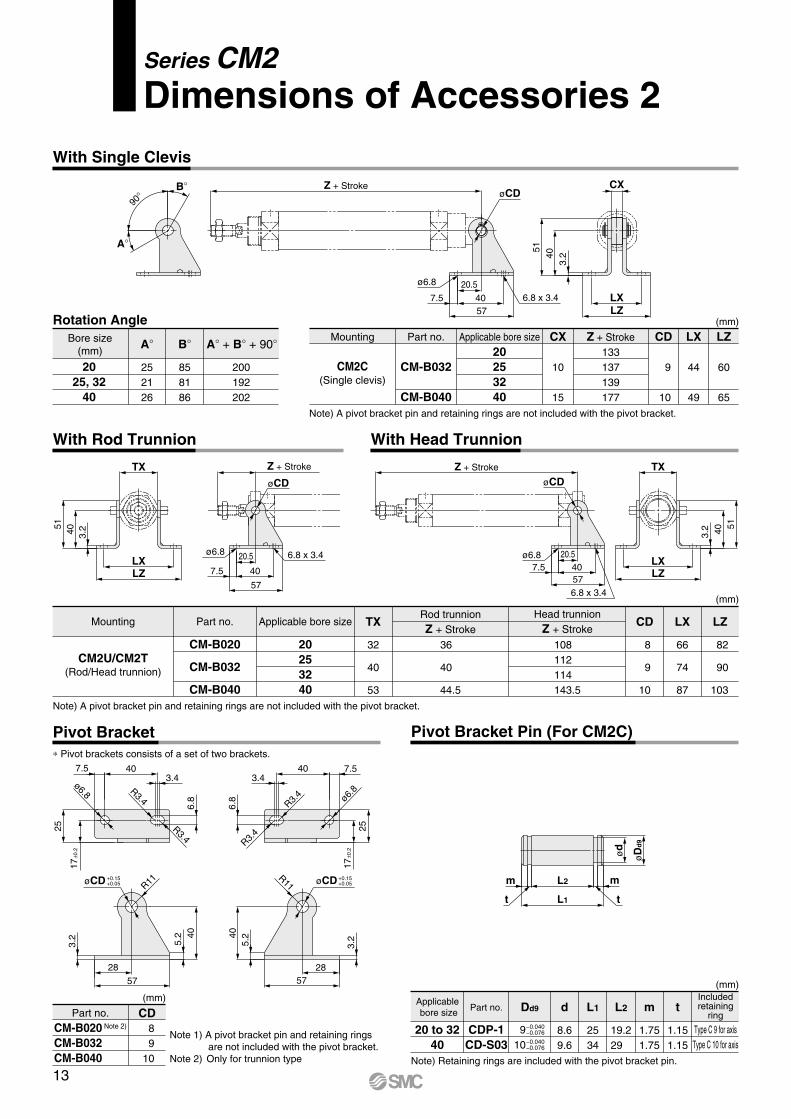
Pivot Bracket
With Rod Trunnion With Head Trunnion
Pivot Bracket Pin (For CM2C)
Rotation Angle
Note) A pivot bracket pin and retaining rings are not included with the pivot bracket.
A + B + 90ABore size(mm)
2025, 32
40
252126
B
858186
200192202
CDPart no.CM-B020 Note 2)
CM-B032CM-B040
89
10
Mounting Part no. Applicable bore size Z + StrokeCX CD
CM2C(Single clevis)
CM-B032
CM-B040
133137139177
20253240
10
15
9
10
LX
44
49
LZ
60
65
(mm)
Note) A pivot bracket pin and retaining rings are not included with the pivot bracket.
Note) Retaining rings are included with the pivot bracket pin.
Pivot brackets consists of a set of two brackets.
Mounting Part no. Applicable bore sizeRod trunnionZ + Stroke
TX CD
CM2U/CM2T(Rod/Head trunnion)
CM-B020
CM-B032
CM-B040
36
40
44.5
Head trunnionZ + Stroke
108112114143.5
20253240
32
40
53
8
9
10
LX
66
74
87
LZ
82
90
103
(mm)
(mm)(mm)
dPart no.Applicablebore size
Includedretaining
ring
20 to 3240
CDP-1CD-S03
Type C 9 for axisType C 10 for axis
Dd9
9−0.040−0.076
10−0.040−0.076
8.69.6
L1
2534
L2
19.229
m
1.751.75
t
1.151.15
Note 1) A pivot bracket pin and retaining rings are not included with the pivot bracket.
Note 2) Only for trunnion type
With Single Clevis
Series CM2Dimensions of Accessories 2
13
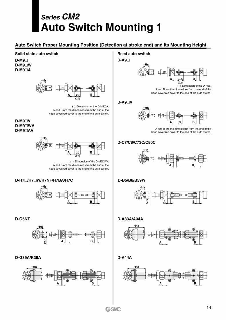
Series CM2Auto Switch Mounting 1
Auto Switch Proper Mounting Position (Detection at stroke end) and Its Mounting Height
D-M9D-M9 WD-M9 A
D-M9 VD-M9 WVD-M9 AV
( ): Dimension of the D-A96.A and B are the dimensions from the end of the
head cover/rod cover to the end of the auto switch.
A and B are the dimensions from the end of thehead cover/rod cover to the end of the auto switch.
( ): Dimension of the D-M9 A.A and B are the dimensions from the end of the
head cover/rod cover to the end of the auto switch.
( ): Dimension of the D-M9 AV.A and B are the dimensions from the end of the
head cover/rod cover to the end of the auto switch.
D-A9
D-A9 V
Reed auto switchSolid state auto switch
D-C7/C8/C73C/C80C
D-B5/B6/B59W
D-A33A/A34A
D-A44A
D-H7 /H7 W/H7NF/H7BA/H7C
D-G5NT
D-G39A/K39A
A
A
A
AHs
22(24)
B
Hs
16
24.5(22)
B
Hs
16
20(22)
B
Hs
16
22 B
A B
Hs
16
Hs16
A B
Hs
24.5 A B
Hs
24.5 A B
Hs
A B
Hs
Hs
A B
A B
16
14
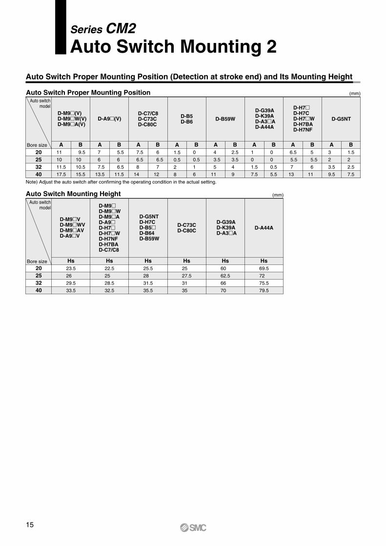
Auto Switch Mounting HeightAuto switch
model
Bore size20253240
Hs22.5
25
28.5
32.5
Hs25.5
28
31.5
35.5
Hs25
27.5
31
35
Hs60
62.5
66
70
Hs69.5
72
75.5
79.5
D-G5NTD-H7CD-B5D-B64D-B59W
D-G39AD-K39AD-A3 A
D-C73CD-C80C D-A44A
Hs23.5
26
29.5
33.5
D-M9 VD-M9 WVD-M9 AVD-A9 V
D-M9D-M9 WD-M9 AD-A9D-H7D-H7 WD-H7NFD-H7BAD-C7/C8
(mm)
Auto Switch Proper Mounting PositionAuto switch
model
Bore size A1.5
0.5
2
8
B0
0.5
1
6
A B2.5
3.5
4
9
A1
0
1.5
7.5
B0
0
0.5
5.5
A B A3
2
3.5
9.5
B1.5
2
2.5
7.5
D-B5D-B6
B
D-C7/C8D-C73CD-C80C
A7
6
7.5
13.5
B 5.5
6
6.5
11.5
D-A9 (V)D-M9 (V)D-M9 W(V)D-M9 A(V)
D-B59W
D-H7D-H7CD-H7 WD-H7BAD-H7NF
D-G5NT
Note) Adjust the auto switch after confirming the operating condition in the actual setting.
B 9.5
10
10.5
15.5
D-G39AD-K39AD-A3 AD-A44A
(mm)
20253240
Auto Switch Proper Mounting Position (Detection at stroke end) and Its Mounting Height
A11
10
11.5
17.5
A 7.5
6.5
8
14
6
6.5
7
12
4
3.5
5
11
6.5
5.5
7
13
5
5.5
6
11
Series CM2Auto Switch Mounting 2
15
A 15
B
3.5
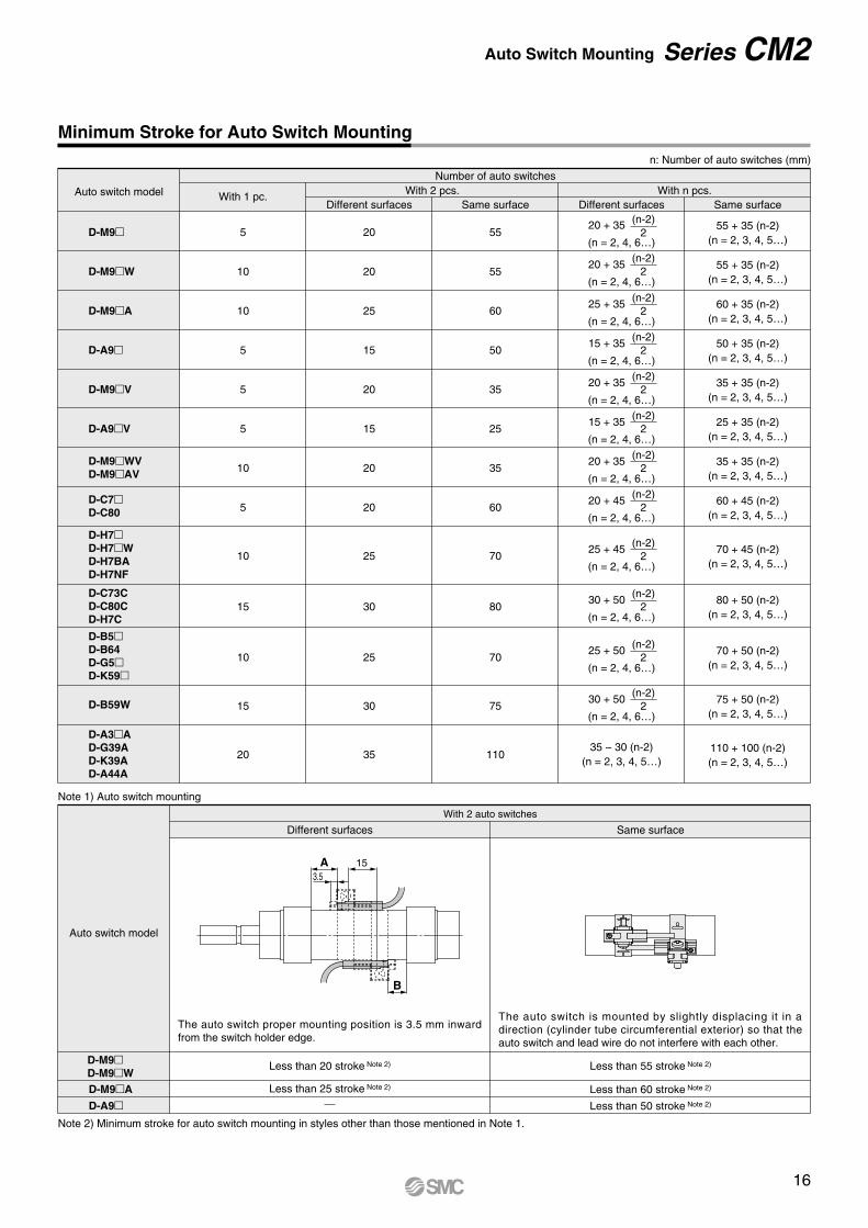
Minimum Stroke for Auto Switch Mounting
D-M9
D-M9 W
D-M9 A
D-A9
D-M9 V
D-A9 V
Auto switch model With 1 pc. With 2 pcs.Different surfaces
With n pcs.Number of auto switches
5
10
10
5
5
5
10
5
10
15
10
15
20
20
20
25
15
20
15
20
20
25
30
25
30
35
Same surface
55
55
60
50
35
25
35
60
70
80
70
75
110
Same surface
n: Number of auto switches (mm)
Different surfaces
20 + 35
(n = 2, 4, 6…)
(n-2)2
20 + 35
(n = 2, 4, 6…)
(n-2)2
25 + 35
(n = 2, 4, 6…)
(n-2)2
15 + 35
(n = 2, 4, 6…)
(n-2)2
20 + 35
(n = 2, 4, 6…)
(n-2)2
20 + 35
(n = 2, 4, 6…)
(n-2)2
20 + 45
(n = 2, 4, 6…)
(n-2)2
25 + 45
(n = 2, 4, 6…)
(n-2)2
30 + 50
(n = 2, 4, 6…)
(n-2)2
25 + 50
(n = 2, 4, 6…)
(n-2)2
30 + 50
(n = 2, 4, 6…)
(n-2)2
35 − 30 (n-2)(n = 2, 3, 4, 5…)
15 + 35
(n = 2, 4, 6…)
(n-2)2
Note 1) Auto switch mounting
Note 2) Minimum stroke for auto switch mounting in styles other than those mentioned in Note 1.
Auto switch model
With 2 auto switches
Different surfaces Same surface
D-M9D-M9 W
Less than 20 stroke Note 2) Less than 55 stroke Note 2)
The auto switch is mounted by slightly displacing it in a direction (cylinder tube circumferential exterior) so that the auto switch and lead wire do not interfere with each other.
The auto switch proper mounting position is 3.5 mm inward from the switch holder edge.
D-M9 A
D-A9
Less than 25 stroke Note 2) Less than 60 stroke Note 2)
Less than 50 stroke Note 2)
D-M9 WVD-M9 AV
D-C7D-C80
D-H7D-H7 WD-H7BAD-H7NF
D-C73CD-C80CD-H7C
D-B5D-B64D-G5D-K59
D-B59W
D-A3 AD-G39AD-K39AD-A44A
55 + 35 (n-2)(n = 2, 3, 4, 5…)
55 + 35 (n-2)(n = 2, 3, 4, 5…)
60 + 35 (n-2)(n = 2, 3, 4, 5…)
50 + 35 (n-2)(n = 2, 3, 4, 5…)
35 + 35 (n-2)(n = 2, 3, 4, 5…)
25 + 35 (n-2)(n = 2, 3, 4, 5…)
35 + 35 (n-2)(n = 2, 3, 4, 5…)
60 + 45 (n-2)(n = 2, 3, 4, 5…)
70 + 45 (n-2)(n = 2, 3, 4, 5…)
80 + 50 (n-2)(n = 2, 3, 4, 5…)
70 + 50 (n-2)(n = 2, 3, 4, 5…)
75 + 50 (n-2)(n = 2, 3, 4, 5…)
110 + 100 (n-2)(n = 2, 3, 4, 5…)
16
Auto Switch Mounting Series CM2

(1) BJ -1 is a set of “a” and “b”.(2) BM2- A(S) is a set of “c” and “d”.
Band (c) is mounted so that the projected part is on the internal side (contact side with the tube).BJ4-1 (Switch bracket: White)BJ5-1 (Switch bracket: Transparent)
Switch bracket(Resin)
Auto switch
a
Switch holder(Zinc)
b
Auto switch mounting screwd
Auto switch mounting bandc
Auto Switch Mounting Brackets/Part No.
Auto switch modelBore size (mm)
D-M9 (V)D-M9 W(V)D-A9 (V)
D-C7 /C80D-C73C/C80CD-H7D-H7 WD-H7NFD-H7BA
D-B5 /B64D-B59WD-G5 /K59D-G5 W/K59WD-G5BA/G59FD-G5NTD-G5NB
D-A3 A/A44AD-G39A/K39A
D-M9 A(V)
20
BA2-020
BM3-020
Note 1)
BM5-020
25
BA2-025
BM3-025
Note 1)
BM5-025
32
BA2-032
BM3-032
Note 1)
BM5-032
40
BA2-040
BM2-020A BM2-025A BM2-032A BM2-040A
BM3-040
Note 1)
BM5-040
Note 2)
BM5-020SNote 2)
BM5-025SNote 2)
BM5-032SNote 2)
BM5-040S
Note 1) Set part number which includes the auto switch mounting band (BM2- A) and the holder kit (BJ5-1/Switch bracket: Transparent). Since the switch bracket (made from nylon) are affected in an environment where alcohol, chloroform, methylamines, hydrochloric acid or sulfuric acid is splashed over, so it cannot be used. Please consult SMC regarding other chemicals.
Note 2) Set part number which includes the auto switch mounting band (BM2- AS/Stainlesssteel screw) and the holder kit (BJ4-1/Switch bracket: White). Avoid the indicator LED for mounting the switch bracket. As the indicator LED is projected from the switch unit, indicator LED may be damaged if the switch bracket is fixed on the indicator LED.
Operating Range
Auto switch modelBore size
20 25 32
3
6
7
8
12
4
7 8
3
6
8
8
12
4
8.59
4
6
8
9
13
4.5
99
40
3.5
6
8
9
13
5
109
D-C7 /C80D-C73C/C80CD-B5 /B64D-A3 A/A44A
D-H7 /H7 W/H7BAD-G5NT/H7NF
D-B59W
D-H7CD-G39A/K39A
D-M9 (V)D-M9 W(V)D-M9 A(V)
D-A9
(mm)
Values which include hysteresis are for guideline purposes only, they are not a guarantee (assuming approximately 30% dispersion) and may change substantially depending on the ambient environment.
Series CM2Auto Switch Mounting 3
[Stainless Steel Mounting Screw]The following stainless steel mounting screw kit is available. Use it in accordance with the operating environment. (Since the auto switch mounting bracket is not included, order it separately.)
BBA4: For D-C7/C8/H7 typesNote 3) Refer to page 1358 in Best Pneumatics No. 2 for details on the BBA4.The above stainless steel screws are used when a cylinder is shipped with the D-H7BA auto switch. When only an auto switch is shipped independently, the BBA4 is attached.
Other than the applicable auto switches listed in “How to Order,” the following auto switches are mountable.Refer to pages 1263 to 1371 in Best Pneumatics No. 2 for detailed specifications.
Type Model FeaturesElectrical entry (Entry direction)
D-H7A1/H7A2/H7B
D-H7NW/H7PW/H7BW
D-H7BA
D-G5NT
D-B53/C73/C76
D-C80
—
Diagnosis indication (2-color indication)
Water resistant (2-color indication)
With timer
—
Without indicator light
Grommet (In-line)
Sold state
Reed
With pre-wired connector is also available for solid state auto switches. For details, refer to pages 1328 and 1329 in Best Pneumatics No. 2.Normally closed (NC = b contact) solid state auto switches (D-F9G/F9H) are also available. For details, refer to page 1290 in Best Pneumatics No. 2. Wide range detection type, solid state auto switch (D-G5NBL) is also available. For details, refer to page 1320 in Best Pneumatics No. 2.
17

Example of AND (Series) and OR (Parallel) Connection
Sink Input Specifications Source Input Specifications
Prior to UseAuto Switch Connection and Example
Load voltage at ON = Power supply voltage – Residual voltage x 2 pcs. = 24 V − 4 V x 2 pcs. = 16 V
Example: Power supply voltage 24 VDC Auto switch internal voltage drop 4 V
Load voltage at OFF = Leakage current x 2 pcs. x Load impedance= 1 mA x 2 pcs. x 3 k= 6 V
Example: Load impedance 3 k Auto switch leakage current 1 mA
(Solid state) (Reed)When two auto switches are connected in series, malfunction may occur because the load voltage will decrease in the ON state. The indicator lights will light up when both of the auto switches are in the ON state.
When two auto switches are connected in parallel, malfunction may occur because the load voltage will increase in the OFF state.
Because there is no leak-age current, the load vol-tage will not increase in the OFF state. However, depending on the num-ber of auto switches in the ON state, the indica-tor lights may sometimes grow dim or not light up, due to the dispersion and reduction of the current flowing to the auto switches.
Connect according to the applicable PLC input specifications, as the connection method will vary depending on the PLC input specifications.
Relay
Relay
Input
COM
COM
Input
COM
Input
COM
Input
2-wire,OR connection
2-wire,AND connection
3-wire,OR connection for PNP output
(Performed with auto switches only)(Using relays)
3-wire,AND connection for PNP output
3-wire,OR connection for NPN output
(Performed with auto switches only)(Using relays)
3-wire,AND connection for NPN output
(PLC internal circuit)
(PLC internal circuit)
(PLC internal circuit)
(PLC internal circuit)
2-wire
3-wire, PNP
2-wire
3-wire, NPN
Load
Load
Load
Load Load
Load Load
Load
Blue
Black
Brown
Auto switch 2
Blue
Black
Brown
Auto switch 1
Blue
Black
Brown
Auto switch 2
Blue
Black
Brown
Auto switch 1
Blue
Black
Brown
Auto switch 2
Blue
Black
Brown
Auto switch 1
Blue
Black
Brown
Auto switch 2
Blue
Black
Brown
Auto switch 1
Blue
Brown
Auto switch 2
Blue
Brown
Auto switch 1
Blue
Black
Brown
Auto switch 2
Blue
Black
Brown
Auto switch 1
Blue
Brown
Auto switch 2
Blue
Brown
Auto switch 1
Blue
Black
Brown
Auto switch 2
Blue
Black
Brown
Auto switch 1
Blue
Brown
Blue
Brown
Blue
Black
Brown
Blue
Black
Brown
Auto switch
Auto switch
Auto switch
Auto switch
18

3 x M4 x 0.72 x Hexagon socket head set screw
Viewed from the rod side, the ports are rendered A, B, C and D, in the clockwise direction.
Series CM2Made to OrderPlease contact SMC for detailed dimensions, specifications and lead times.
Made toOrder
Position of the port on the rod cover and head cover is changed from the standard type.
XC3
Rod port location on the rod cover seen from the rod side
Standard model no.
How to Order
Mounting nut with set screw
Rod port location on the head cover seen from the rod side
Specifications: Same as standard type
Dimensions: Same as standard type
Specifications: Same as standard type
Dimensions: Same as standard type
Rod port location on the head cover seen from the rod side.
A B
Position of the port on the head cover is changed to the axial direction.
XC20Standard model no.
How to Order
Only available for mounting type B: Basic, L: Axial foot, F: Rod flange, G: Head flange, BZ: Boss-cut/Basic, FZ: Boss-cut/Rod flange
Only available for mounting type B: Basic, L: Axial foot, F: Rod flange, G: Head flange, BZ: Boss-cut/Basic, FZ: Boss-cut/Rod flange
Specifications: Same as standard type
In order to prevent the mounting nut from being loosen, set screw should be tighter from the two directions to fix the mounting nut.
XC52Standard model no.
How to Order
Dimensions
Symbol
-XC3Special Port Location1
Symbol
-XC20Head Cover Axial Port2
Symbol
-XC52Mounting Nut with Set Screw3
Port
(Dimensions other than below arethe same as the basic type.)
19

Food grade grease (certified by NSF-H1) is used as lubricant.
XC85
Grease for food processing machine
Standard model no.
How to Order
Specifications: Same as standard model
Dimensions: Same as standard model
When grease is necessary for maintenance, grease pack is available, please order it separately.Grease pack part number: GR-H-010 (10 g)
When the product is used in an area of liquid splash, or a water resistant function is required for the product, please consult SMC.
Operating Environment
Caution1. Avoid installing and using a cylinder inside a food
zone.<Not installable>Food zone……………An environment where food which will
be sold as merchandize, directly touches the cylinder’s components.
Splash zone…………An environment where food which will not be sold as merchandize, directly touches the cylinder’s components.
<Installable>Non-food zone………An environment where there is no contact
with food.
X446Standard model no.
How to Order
Specifications: Same as standard model
Dimensions: Same as standard model
When grease is necessary for maintenance, grease pack is available, please order it separately.Grease pack part number: GR-F-005 (5 g)
Symbol
-XC85Grease for Food Processing Equipment4
Symbol
-X446PTFE Grease5
FoodNon-food zone
Installable
Container
Food zoneNot installable
Splash zoneNot installable
20
Made to Order Series CM2
Akihabara UDX 15F, 4-14-1, Sotokanda, Chiyoda-ku, Tokyo 101-0021, JAPANPhone: 03-5207-8249 Fax: 03-5298-5362http://www.smcworld.com© 2012 SMC Corporation All Rights Reserved
Specifications are subject to change without prior notice and any obligation on the part of the manufacturer.
1st printing QV printing QV 8150SZ Printed in Japan.D-DN
1. The compatibility of the product is the responsibility of the person who designs the equipment or decides its specifications.Since the product specified here is used under various operating conditions, its compatibility with specific equipment must be decided by the person who designs the equipment or decides its specifications based on necessary analysis and test results. The expected performance and safety assurance of the equipment will be the responsibility of the person who has determined its compatibility with the product. This person should also continuously review all specifications of the product referring to its latest catalog information, with a view to giving due consideration to any possibility of equipment failure when configuring the equipment.
2. Only personnel with appropriate training should operate machinery and equipment.The product specified here may become unsafe if handled incorrectly. The assembly, operation and maintenance of machines or equipment including our products must be performed by an operator who is appropriately trained and experienced.
3. Do not service or attempt to remove product and machinery/equipment until safety is confirmed.1. The inspection and maintenance of machinery/equipment should only be
performed after measures to prevent falling or runaway of the driven objects have been confirmed.
2. When the product is to be removed, confirm that the safety measures as mentioned above are implemented and the power from any appropriate source is cut, and read and understand the specific product precautions of all relevant products carefully.
3. Before machinery/equipment is restarted, take measures to prevent unexpected operation and malfunction.
4. Contact SMC beforehand and take special consideration of safety measures if the product is to be used in any of the following conditions.1. Conditions and environments outside of the given specifications, or use
outdoors or in a place exposed to direct sunlight.2. Installation on equipment in conjunction with atomic energy, railways, air
navigation, space, shipping, vehicles, military, medical treatment, combustion and recreation, or equipment in contact with food and beverages, emergency stop circuits, clutch and brake circuits in press applications, safety equipment or other applications unsuitable for the standard specifications described in the product catalog.
3. An application which could have negative effects on people, property, or animals requiring special safety analysis.
4. Use in an interlock circuit, which requires the provision of double interlock for possible failure by using a mechanical protective function, and periodical checks to confirm proper operation.
Warning
Limited warranty and Disclaimer/Compliance Requirements The product used is subject to the following “Limited warranty and Disclaimer” and “Compliance Requirements”.Read and accept them before using the product.
1. The product is provided for use in manufacturing industries.The product herein described is basically provided for peaceful use in manufacturing industries. If considering using the product in other industries, consult SMC beforehand and exchange specifications or a contract if necessary. If anything is unclear, contact your nearest sales branch.
Caution
Limited warranty and Disclaimer1. The warranty period of the product is 1 year in service or 1.5 years after
the product is delivered, whichever is first. 2)
Also, the product may have specified durability, running distance or replacement parts. Please consult your nearest sales branch.
2. For any failure or damage reported within the warranty period which is clearly our responsibility, a replacement product or necessary parts will be provided. This limited warranty applies only to our product independently, and not to any other damage incurred due to the failure of the product.
3. Prior to using SMC products, please read and understand the warranty terms and disclaimers noted in the specified catalog for the particular products.
2) Vacuum pads are excluded from this 1 year warranty.A vacuum pad is a consumable part, so it is warranted for a year after it is delivered. Also, even within the warranty period, the wear of a product due to the use of the vacuum pad or failure due to the deterioration of rubber material are not covered by the limited warranty.
Compliance Requirements1. The use of SMC products with production equipment for the manufacture of
weapons of mass destruction (WMD) or any other weapon is strictly prohibited.
2. The exports of SMC products or technology from one country to another are governed by the relevant security laws and regulations of the countries involved in the transaction. Prior to the shipment of a SMC product to another country, assure that all local rules governing that export are known and followed.
These safety instructions are intended to prevent hazardous situations and/or equipment damage. These instructions indicate the level of potential hazard with the labels of “Caution,” “Warning” or “Danger.” They are all important notes for safety and must be followed in addition to International Standards (ISO/IEC) 1), and other safety regulations.
1) ISO 4414: Pneumatic fluid power – General rules relating to systems. ISO 4413: Hydraulic fluid power – General rules relating to systems. IEC 60204-1: Safety of machinery – Electrical equipment of machines. (Part 1: General requirements) ISO 10218-1: Manipulating industrial robots – Safety. etc.
Caution indicates a hazard with a low level of risk which, if not avoided, could result in minor or moderate injury.
Warning indicates a hazard with a medium level of risk which, if not avoided, could result in death or serious injury.
Caution:
Warning:
Danger :Danger indicates a hazard with a high level of risk which, if not avoided, will result in death or serious injury.
Safety Instructions
Safety Instructions Be sure to read “Handling Precautions for SMC Products” (M-E03-3) before using.