Embed Size (px)
Citation preview
Shear Reinforcement for Slabs
ACI 421.1R-99
Reported by Joint ACI-ASCE Committee 421
Scott D. B. Alexander Neil L. Hammill Edward G. Nawy
Pinaki R. Chakrabarti J. Leroy Hulsey Eugenio M. Santiago
William L. Gamble Theodor Krauthammer* Sidney H. Simmonds
Amin Ghali* James S. Lai Miroslav F. Vejvoda
Hershell Gill Mark D. Marvin Stanley C. Woodson*
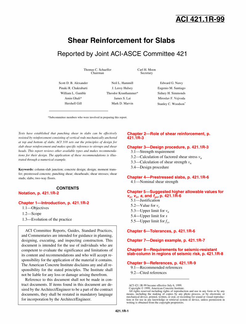
Tests have established that punching shear in slabs can be effectivelyresisted by reinforcement consisting of vertical rods mechanically anchoredat top and bottom of slabs. ACI 318 sets out the principles of design forslab shear reinforcement and makes specific reference to stirrups and shearheads. This report reviews other available types and makes recommenda-tions for their design. The application of these recommendations is illus-trated through a numerical example.
Keywords: column-slab junction; concrete design; design; moment trans-fer; prestressed concrete; punching shear; shearheads; shear stresses; shearstuds; slabs; two-way floors.
Thomas C. SchaefferChairman
Carl H. MoonSecretary
*Subcommittee members who were involved in preparing this report.
ACI Committee Reports, Guides, Standard Practices,and Commentaries are intended for guidance in planning,designing, executing, and inspecting construction. Thisdocument is intended for the use of individuals who arecompetent to evaluate the significance and limitations ofits content and recommendations and who will accept re-sponsibility for the application of the material it contains.The American Concrete Institute disclaims any and all re-sponsibility for the stated principles. The Institute shallnot be liable for any loss or damage arising therefrom.
Reference to this document shall not be made in con-tract documents. If items found in this document are de-sired by the Architect/Engineer to be a part of the contractdocuments, they shall be restated in mandatory languagefor incorporation by the Architect/Engineer.
CONTENTSNotation, p. 421.1R-2
Chapter 1—Introduction, p. 421.1R-21.1—Objectives
1.2—Scope
1.3—Evolution of the practice
421.1
ACI 421.1R-99 became effective July 6, 1999.Copyright 1999, American Concrete Institute.All rights reserved including rights of reproduction and use in any form or by any
means, including the making of copies by any photo process, or by electronic ormechanical device, printed, written, or oral, or recording for sound or visual reproduc-tion or for use in any knowledge or retrieval system or device, unless permission inwriting is obtained from the copyright proprietors.
Chapter 2—Role of shear reinforcement, p. 421.1R-3
Chapter 3—Design procedure, p. 421.1R-33.1—Strength requirement3.2—Calculation of factored shear stress vu
3.3—Calculation of shear strength vn
3.4—Design procedure
Chapter 4—Prestressed slabs, p. 421.1R-64.1—Nominal shear strength
Chapter 5—Suggested higher allowable values for vc, vn, s, and fyv, p. 421.1R-6
5.1—Justification5.2—Value for vc
5.3—Upper limit for vn
5.4—Upper limit for s5.5—Upper limit for fyv
Chapter 6—Tolerances, p. 421.1R-6
Chapter 7—Design example, p. 421.1R-7
Chapter 8—Requirements for seismic-resistant slab-column in regions of seismic risk, p. 421.1R-8
Chapter 9—References, p. 421.1R-99.1—Recommended references9.2—Cited references
R-1
421.1R-2 ACI COMMITTEE REPORT
Appendix A—Details of shear studs, p. 421.1R-10A.1—Geometry of stud shear reinforcementA.2—Stud arrangementsA.3—Stud length
Appendix B—Properties of critical sections of general shape, p. 421.1R-11
Appendix C—Values of vc within shear reinforced zone, p. 421.1R-13
NOTATIONAc = area of concrete of assumed critical sectionAv = cross-sectional area of the shear studs on one
peripheral line parallel to the perimeter of the column section
bo = perimeter of critical sectioncb, ct = clear concrete cover of reinforcement to bottom
and top slab surfaces, respectively.cx, cy = size of a rectangular column measured in two
orthogonal span directionsd = effective depth of slabdb = nominal diameter of flexural reinforcing barsD = stud diameterfc′ = specified compressive strength of concretefct = average splitting tensile strength of lightweight
aggregate concretefpc = average value of compressive stress in concrete in
the two directions (after allowance for all prestresslosses) at centroid of cross section
fyv = specified yield strength of shear studsh = overall thickness of slabIx, Iy = second moment of area of assumed critical section
about the axis x and yJx, Jy = property of assumed critical section analogous to
polar moment of inertia about the axes x and yl = length of a segment of the assumed critical sectionlx , ly = projections of assumed critical section on principal
axes x and ylx1, ly1 = length of sides in the x and y directions of the critical
section at d/2 from column facelx2 , ly2 = length of sides in the x and y directions of the critical
section at d/2 outside the outermost studsls = length of stud (including top anchor plate thickness;
see Fig. 7.1)
Mux, Muy= factored unbalanced moments transferredbetween the slab and the column about centroidal axes x and y of the assumed critical section
nx, ny = numbers of studs per line/strip running in x and y directions
s = spacing between peripheral lines of studsso = spacing between first peripheral line of studs and
column facevc = nominal shear strength provided by concrete in
presence of shear studsvn = nominal shear strength at a critical sectionvs = nominal shear strength provided by studsvu = maximum shear stress due to factored forcesVp = vertical component of all effective prestress forces
crossing the critical sectionVu = factored shear forcex, y = coordinates of the point at which vu is maximum
with respect to the centroidal principal axes x and y of the assumed critical section
α = distance between column face and a critical section divided by d
αs = dimensionless coefficient equal to 40, 30, and 20 for interior, edge and corner columns, respectively
βc = ratio of long side to short side of column cross section
βp = constant used to compute vc in prestressed slabsγvx, γvy = fraction of moment between slab and column that
is considered transferred by eccentricity of the shear about the axes x and y of the assumed critical section
φ = strength-reduction factor = 0.85
CHAPTER 1—INTRODUCTION1.1—Objectives
In flat-plate floors, slab-column connections are subjectedto high shear stresses produced by the transfer of axial loadsand bending moments between slab and columns. Section11.12.3 of ACI 318 allows the use of shear reinforcement forslabs and footings in the form of bars, as in the vertical legsof stirrups. ACI 318R emphasizes the importance of anchor-age details and accurate placement of the shear reinforce-ment, especially in thin slabs. A general procedure forevaluation of the punching shear strength of slab-columnconnections is given in Section 11.12 of ACI 318.
Shear reinforcement consisting of vertical rods (studs) orthe equivalent, mechanically anchored at each end, can beused. In this report, all types of mechanically-anchored shearreinforcement are referred to as “shear stud” or “stud.” To befully effective, the anchorage must be capable of developingthe specified yield strength of the studs. The mechanical an-chorage can be obtained by heads or strips connected to thestuds by welding. The heads can also be formed by forgingthe stud ends.
1.2—ScopeThese recommendations are for the design of shear rein-
forcement using shear studs in slabs. The design is in accor-dance with ACI 318, treating a stud as the equivalent of avertical branch of a stirrup. A numerical design example isincluded.
1.3—Evolution of the practiceExtensive tests1-6 have confirmed the effectiveness of me-
chanically-anchored shear reinforcement, such as shown inFig. 1.1,7 in increasing the strength and ductility of slab-col-
umn connections subjected to concentric punching or punch-ing combined with moment. The Canadian Concrete DesignCode (CSA A23.3) and the German Construction SupervisingAuthority, Berlin,8 allow the use of shear studs for flat slabs(Fig. 1.2). Design rules have been presented9 for applicationof British Standard BS 8110 to stud design for slabs. Various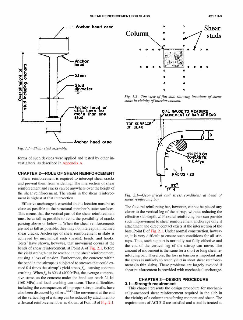
421.1R-3SHEAR REINFORCEMENT FOR SLABS
Fig. 1.1—Shear stud assembly.
forms of such devices were applied and tested by other in-vestigators, as described in Appendix A.
CHAPTER 2—ROLE OF SHEAR REINFORCEMENTShear reinforcement is required to intercept shear cracks
and prevent them from widening. The intersection of shearreinforcement and cracks can be anywhere over the height ofthe shear reinforcement. The strain in the shear reinforce-ment is highest at that intersection.
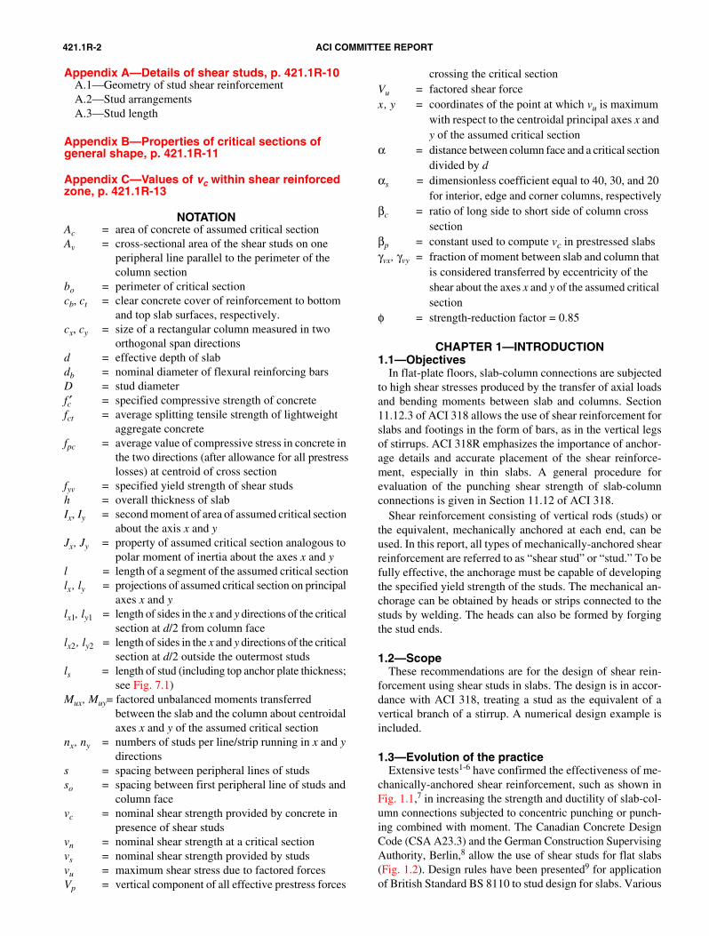
Effective anchorage is essential and its location must be asclose as possible to the structural member’s outer surfaces.This means that the vertical part of the shear reinforcementmust be as tall as possible to avoid the possibility of crackspassing above or below it. When the shear reinforcementsare not as tall as possible, they may not intercept all inclinedshear cracks. Anchorage of shear reinforcement in slabs isachieved by mechanical ends (heads), bends, and hooks.Tests1 have shown, however, that movement occurs at thebends of shear reinforcement, at Point A of Fig. 2.1, before
Fig. 2.1—Geometrical and stress conditions at bend ofshear reinforcing bar.
the yield strength can be reached in the shear reinforcement,causing a loss of tension. Furthermore, the concrete withinthe bend in the stirrups is subjected to stresses that could ex-ceed 0.4 times the stirrup’s yield stress, fyv, causing concretecrushing. When fyv is 60 ksi (400 MPa), the average compres-sive stress on the concrete under the bend can reach 24 ksi(160 MPa) and local crushing can occur. These difficulties,including the consequences of improper stirrup details, havealso been discussed by others.10-13 The movement at the endof the vertical leg of a stirrup can be reduced by attachment toa flexural reinforcement bar as shown, at Point B of Fig. 2.1.
The flexural reinforcing bar, however, cannot be placed anycloser to the vertical leg of the stirrup, without reducing theeffective slab depth, d. Flexural reinforcing bars can providesuch improvement to shear reinforcement anchorage only ifattachment and direct contact exists at the intersection of thebars, Point B of Fig. 2.1. Under normal construction, howev-er, it is very difficult to ensure such conditions for all stir-rups. Thus, such support is normally not fully effective andthe end of the vertical leg of the stirrup can move. Theamount of movement is the same for a short or long shear re-inforcing bar. Therefore, the loss in tension is important andthe stress is unlikely to reach yield in short shear reinforce-ment (in thin slabs). These problems are largely avoided ifshear reinforcement is provided with mechanical anchorage.
CHAPTER 3—DESIGN PROCEDURE 3.1—Strength requirement
This chapter presents the design procedure for mechani-cally-anchored shear reinforcement required in the slab inthe vicinity of a column transferring moment and shear. Therequirements of ACI 318 are satisfied and a stud is treated as
Fig. 1.2—Top view of flat slab showing locations of shearstuds in vicinity of interior column.
421.1R-4 ACI COMMITTEE REPORT
the equivalent of one vertical leg of a stirrup. The equationsof Section 3.3.2 apply when conventional stirrups are used.The shear studs shown in Fig. 1.2 can also represent individ-
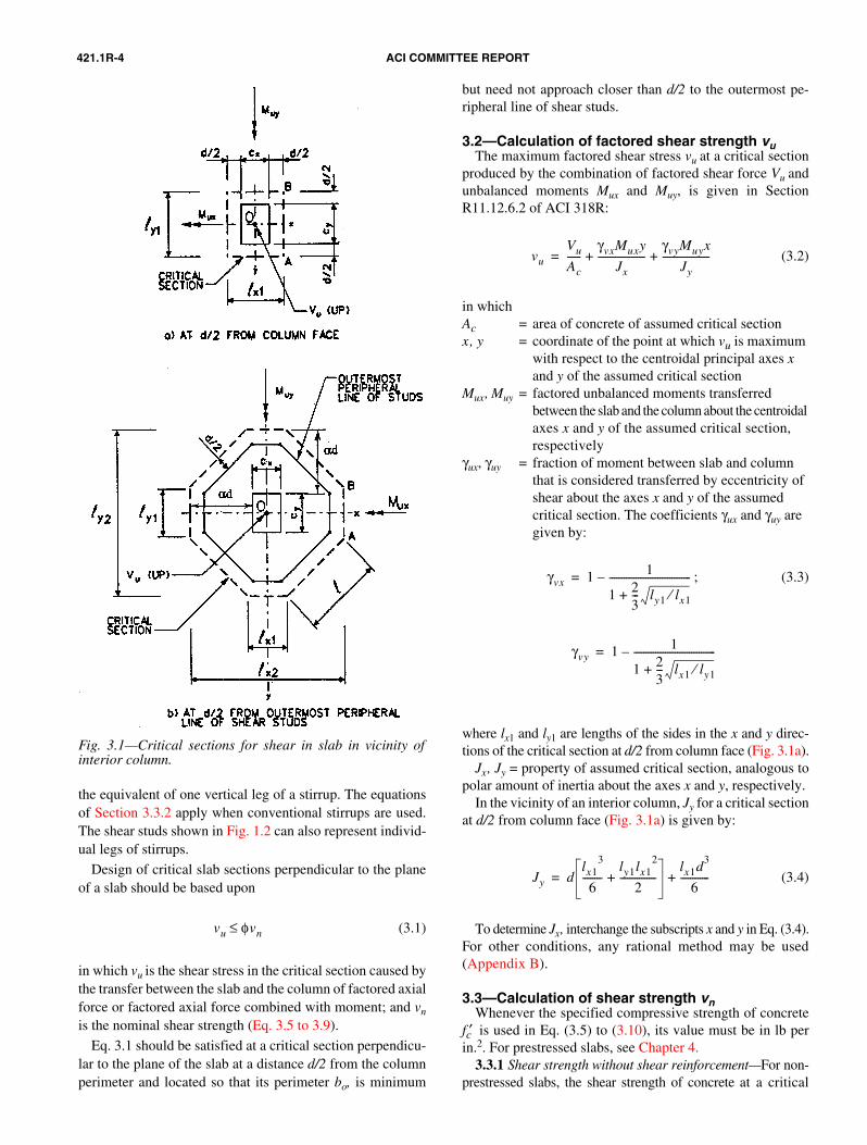
Fig. 3.1—Critical sections for shear in slab in vicinity ofinterior column.
ual legs of stirrups.
Design of critical slab sections perpendicular to the planeof a slab should be based upon
(3.1)
in which vu is the shear stress in the critical section caused bythe transfer between the slab and the column of factored axialforce or factored axial force combined with moment; and vn
is the nominal shear strength (Eq. 3.5 to 3.9).
Eq. 3.1 should be satisfied at a critical section perpendicu-lar to the plane of the slab at a distance d/2 from the columnperimeter and located so that its perimeter bo, is minimum
vu φvn≤
but need not approach closer than d/2 to the outermost pe-ripheral line of shear studs.
3.2—Calculation of factored shear strength vuThe maximum factored shear stress vu at a critical section
produced by the combination of factored shear force Vu andunbalanced moments Mux and Muy, is given in SectionR11.12.6.2 of ACI 318R:
(3.2)
in which Ac = area of concrete of assumed critical sectionx, y = coordinate of the point at which vu is maximum
with respect to the centroidal principal axes x and y of the assumed critical section
Mux, Muy = factored unbalanced moments transferred between the slab and the column about the centroidal axes x and y of the assumed critical section, respectively
γux, γuy = fraction of moment between slab and column that is considered transferred by eccentricity of shear about the axes x and y of the assumed critical section. The coefficients γux and γuy are given by:
; (3.3)
where lx1 and ly1 are lengths of the sides in the x and y direc-tions of the critical section at d/2 from column face (Fig. 3.1a).
Jx, Jy = property of assumed critical section, analogous topolar amount of inertia about the axes x and y, respectively.
In the vicinity of an interior column, Jy for a critical sectionat d/2 from column face (Fig. 3.1a) is given by:
(3.4)
To determine Jx, interchange the subscripts x and y in Eq. (3.4).For other conditions, any rational method may be used(Appendix B).
3.3—Calculation of shear strength vnWhenever the specified compressive strength of concrete
fc′ is used in Eq. (3.5) to (3.10), its value must be in lb perin.2. For prestressed slabs, see Chapter 4.
3.3.1 Shear strength without shear reinforcement—For non-prestressed slabs, the shear strength of concrete at a critical
vu
Vu
Ac------
γvxMuxy
Jx--------------------
γvyMuyx
Jy--------------------+ +=
γvx 1 1
1 23--- ly1 lx1⁄+
----------------------------------–=
γvy 1 1
1 23--- lx1 ly1⁄+
----------------------------------–=
Jy dlx1
3
6--------
ly1lx12
2---------------+
lx1d3
6------------+=
421.1R-5SHEAR REINFORCEMENT FOR SLABS
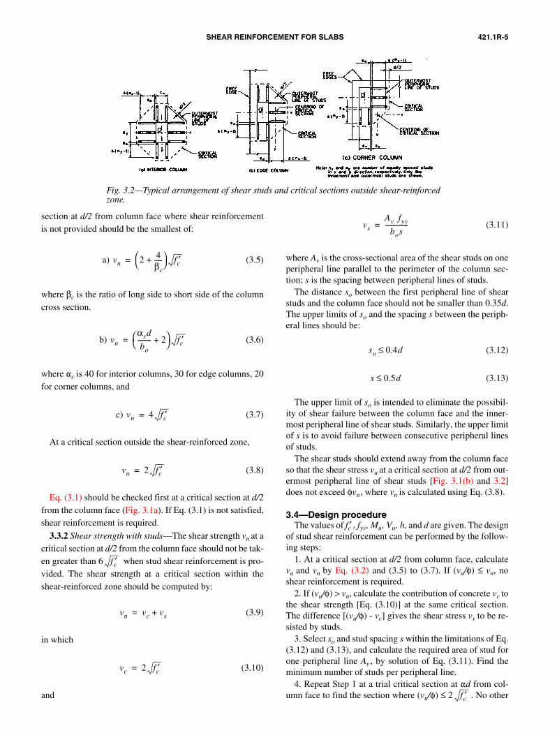
Fig. 3.2—Typical arrangement of shear studs and critical sections outside shear-reinforcedzone.
section at d/2 from column face where shear reinforcementis not provided should be the smallest of:
a) (3.5)
where βc is the ratio of long side to short side of the columncross section.
b) (3.6)
where �s is 40 for interior columns, 30 for edge columns, 20for corner columns, and
c) (3.7)
At a critical section outside the shear-reinforced zone,
(3.8)
Eq. (3.1) should be checked first at a critical section at d/2from the column face (Fig. 3.1a). If Eq. (3.1) is not satisfied,shear reinforcement is required.
3.3.2 Shear strength with studs—The shear strength vn at acritical section at d/2 from the column face should not be tak-en greater than 6 when stud shear reinforcement is pro-vided. The shear strength at a critical section within theshear-reinforced zone should be computed by:
(3.9)
in which
(3.10)
and
vn 2 4βc-----+
fc′=
vn
αsd
bo--------- 2+
fc′=
vn 4 fc′=
vn 2 fc′=
fc′
vn vc vs+=
vc 2 fc′=
(3.11)
where Av is the cross-sectional area of the shear studs on oneperipheral line parallel to the perimeter of the column sec-tion; s is the spacing between peripheral lines of studs.
The distance so between the first peripheral line of shearstuds and the column face should not be smaller than 0.35d.The upper limits of so and the spacing s between the periph-eral lines should be:
(3.12)
(3.13)
The upper limit of so is intended to eliminate the possibil-ity of shear failure between the column face and the inner-most peripheral line of shear studs. Similarly, the upper limitof s is to avoid failure between consecutive peripheral linesof studs.
The shear studs should extend away from the column faceso that the shear stress vu at a critical section at d/2 from out-ermost peripheral line of shear studs [Fig. 3.1(b) and 3.2]does not exceed φvn, where vn is calculated using Eq. (3.8).
3.4—Design procedureThe values of fc′ , fyv, Mu, Vu, h, and d are given. The design
of stud shear reinforcement can be performed by the follow-ing steps:
1. At a critical section at d/2 from column face, calculatevu and vn by Eq. (3.2) and (3.5) to (3.7). If (vu/ φ) ≤ vn, noshear reinforcement is required.
2. If (vu/φ) > vn, calculate the contribution of concrete vc tothe shear strength [Eq. (3.10)] at the same critical section.The difference [(vu/φ) - vc] gives the shear stress vs to be re-sisted by studs.
3. Select so and stud spacing s within the limitations of Eq.(3.12) and (3.13), and calculate the required area of stud forone peripheral line Av, by solution of Eq. (3.11). Find theminimum number of studs per peripheral line.
4. Repeat Step 1 at a trial critical section at �d from col-umn face to find the section where (vu/φ) ≤ 2 . No other
vs
Av fyv
bos---------------=
so 0.4d≤
s 0.5d≤
fc′
421.1R-6 ACI COMMITTEE REPORT
section needs to be checked, and s is to be maintained con-stant. Select the distance between the column face and theoutermost peripheral line of studs to be ≥ (�d - d/2).
The position of the critical section can be determined byselection of nx and ny (Fig. 3.2), in which nx and ny are num-bers of studs per line running in x and y directions, respec-tively. For example, the distance in the x direction betweenthe column face and the critical section is equal to so + (nx -1) s + d/2. The two numbers nx and ny need not be equal; buteach must be ≥ 2.
5. Arrange studs to satisfy the detailing requirements de-scribed in Appendix A.
The trial calculations involved in the above steps are suit-able for computer use.14
CHAPTER 4—PRESTRESSED SLABS4.1—Nominal shear strength
When a slab is prestressed in two directions, the shearstrength of concrete at a critical section at d/2 from the col-umn face where stud shear reinforcement is not provided isgiven by ACI 318:
(4.1)
where βp is the smaller of 3.5 and (αsd/bo + 1.5); fpc is the av-erage value of compressive stress in the two directions (afterallowance for all prestress losses) at centroid of cross sec-tion; Vp is the vertical component of all effective prestressforces crossing the critical section. Eq. (4.1) is applicableonly if the following are satisfied:
a) No portion of the column cross section is closer to a dis-continuous edge than four times the slab thickness;
b) fc′ in Eq. (4.1) is not taken greater than 5000 psi; andc) fpc in each direction is not less than 125 psi, nor taken
greater than 500 psi.If any of the above conditions are not satisfied, the slab
should be treated as non-prestressed and Eq. (3.5) to (3.8) ap-ply. Within the shear-reinforced zone, vn is to be calculatedby Eq. (3.9).
In thin slabs, the slope of the tendon profile is hard to con-trol. Special care should be exercised in computing Vp in Eq.(4.1), due to the sensitivity of its value to the as-built tendonprofile. When it is uncertain that the actual construction willmatch design assumption, a reduced or zero value for Vpshould be used in Eq. (4.1).
CHAPTER 5—SUGGESTED HIGHER ALLOWABLE VALUES FOR vc, vn, s, AND fyv
5.1—JustificationSection 11.5.3 of ACI 318 requires that “stirrups and other
bars or wires used as shear reinforcement shall extend to a dis-tance d from extreme compression fiber and shall be anchoredat both ends according to Section 12.13 to develop the designyield strength of reinforcement.” Test results1-6 show thatstuds with anchor heads of area equal to 10 times the crosssection area of the stem clearly satisfied that requirement.
vn βp fc′ 0.3fpc
Vp
bod--------+ +=
Further, use of the shear device such as shown in Fig. 1.1demonstrated a higher shear capacity. Other researchers, asbriefly mentioned in Appendix A, successfully applied otherconfigurations. Based on these results, following additions1
to ACI 318 are proposed to apply when the shear reinforce-ment is composed of studs with mechanical anchorage capa-ble of developing the yield strength of the rod; the valuesgiven in Section 5.2 through 5.5 may be used.
5.2—Value for vcThe nominal shear strength provided by the concrete in the
presence of shear studs, using Eq. (3.9), can be taken as vc =3 instead of 2 . Discussion on the design value of vcis given in Appendix C.
5.3—Upper limit for vnThe nominal shear strength vn resisted by concrete and
steel in Eq. (3.9) can be taken as high as 8 instead of6 . This enables the use of thinner slabs. Experimentaldata showing that the higher value of vn can be used are in-cluded in Appendix C.
5.4—Upper limit for sThe upper limits for s can be based on the value of vu at the
critical section at d/2 from column face:
when (5.1)
when (5.2)
When stirrups are used, ACI 318 limits s to d/2. The higherlimit for s given by Eq. (5.1) for stud spacing is again justi-fied by tests (see Appendix C).
As mentioned earlier in Chapter 2, a vertical branch of astirrup is less effective than a stud in controlling shear cracksfor two reasons: a) The stud stem is straight over its fulllength, whereas the ends of the stirrup branch are curved; andb) The anchor plates at the top and bottom of the stud ensurethat the specified yield strength is provided at all sections ofthe stem. In a stirrup, the specified yield strength can be de-veloped only over the middle portion of the vertical legswhen they are sufficiently long.
5.5—Upper limit for fyvSection 11.5.2 of ACI 318 limits the design yield strength
for stirrups as shear reinforcement to 60,000 psi. Research15-17
has indicated that the performance of higher-strength studsas shear reinforcement in slabs is satisfactory. In this exper-imental work, the stud shear reinforcement in slab-columnconnections reached yield stress higher than 72,000 psi,without excessive reduction of shear resistance of concrete.Thus, when studs are used, fyv can be as high as 72,000 psi.
CHAPTER 6—TOLERANCESShear reinforcement, in the form of stirrups or studs, can be
ineffective if the specified distances so and s are not controlled
fc′ fc′
fc′fc′
s 0.75d≤vu
φ----- 6 fc′≤
s 0.5d≤vu
φ----- 6 fc′>
421.1R-7SHEAR REINFORCEMENT FOR SLABS
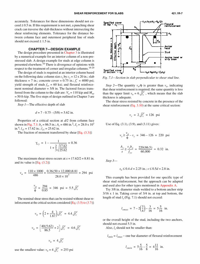
Fig. 7.1—Section in slab perpendicular to shear stud line.
accurately. Tolerances for these dimensions should not ex-ceed ± 0.5 in. If this requirement is not met, a punching shearcrack can traverse the slab thickness without intersecting theshear reinforcing elements. Tolerance for the distance be-tween column face and outermost peripheral line of studsshould not exceed ± 1.5 in.
CHAPTER 7—DESIGN EXAMPLEThe design procedure presented in Chapter 3 is illustrated
by a numerical example for an interior column of a non-pre-stressed slab. A design example for studs at edge column ispresented elsewhere.18 There is divergence of opinions withrespect to the treatment of corner and irregular columns.18-20
The design of studs is required at an interior column basedon the following data: column size cx by cy = 12 x 20 in.; slabthickness = 7 in.; concrete cover = 0.75 in.; fc′ = 4000 psi;yield strength of studs fyv = 60 ksi; and flexural reinforce-ment nominal diameter = 5/8 in. The factored forces trans-ferred from the column to the slab are: Vu = 110 kip and Muy= 50 ft-kip. The five steps of design outlined in Chapter 3 arefollowed:
Step 1—The effective depth of slab
d = 7 - 0.75 - (5/8) = 5.62 in.
Properties of a critical section at d/2 from column faceshown in Fig. 7.1: bo = 86.5 in.; Ac = 486 in.2; Jy = 28.0 x 10³
in.4; lx1 = 17.62 in.; ly1 = 25.62 in.The fraction of moment transferred by shear [Eq. (3.3)]:
The maximum shear stress occurs at x = 17.62/2 = 8.81 in.and its value is [Eq. (3.2)]:
The nominal shear stress that can be resisted without shear re-inforcement at the critical section considered [Eq. (3.5) to (3.7)]:
use the smallest value: vn = 4 = 253 psi
γvy 1 1
1 23--- 17.62
25.62-------------+
------------------------------ 0.36=–=
vu110 1000×
486--------------------------- 0.36 50 12,000×( )8.81
28.0 103×
------------------------------------------------------- 294 psi=+=
vu
φ----- 294
0.85---------- 346 psi 5.5 fc′= = =
vn 2 41.67----------+
fc′ 4.4 fc′= =
vn40 5.62( )
86.5--------------------- 2+ fc′ 4.6 fc′= =
vn 4 fc′=
fc′
Step 2—The quantity vn/φ is greater than vn, indicatingthat shear reinforcement is required; the same quantity is lessthan the upper limit vn = 6 , which means that the slabthickness is adequate.
The shear stress resisted by concrete in the presence of theshear reinforcement (Eq. 3.10) at the same critical section:
Use of Eq. (3.1), (3.9), and (3.11) gives:
Step 3—
so ≤ 0.4 d = 2.25 in.; s ≤ 0.5d = 2.8 in.
This example has been provided for one specific type ofshear stud reinforcement, but the approach can be adaptedand used also for other types mentioned in Appendix A.
Try 3/8 in. diameter studs welded to a bottom anchor strip3/16 x 1 in. Taking cover of 3/4 in. at top and bottom, thelength of stud ls (Fig. 7.1) should not exceed:
or the overall height of the stud, including the two anchors,should not exceed 5.5 in.
Also, ls should not be smaller than:
lsmin = lsmax − one bar diameter of flexural reinforcement
fc′
vc 2 fc′ 126 psi==
vs
vu
φ----- vc–≥ 346 126– 220 psi= =
Av
s-----
vsbo
fyv----------≥ 220 86.5( )
60,000------------------------ 0.32 in.= =
lsmax 7 2 34---
– 316------– 5 5
16------ in.= =
lsmin 5 516------ 5
8---– 411
16------ in.= =
421.1R-8 ACI COMMITTEE REPORT
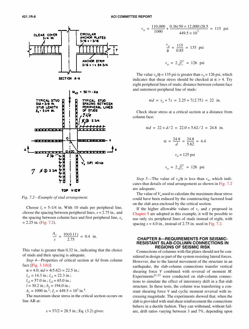
Choose ls = 5-1/4 in. With 10 studs per peripheral line,choose the spacing between peripheral lines, s = 2.75 in., andthe spacing between column face and first peripheral line, so= 2.25 in. (Fig. 7.2).
This value is greater than 0.32 in., indicating that the choiceof studs and their spacing is adequate.
Step 4—Properties of critical section at 4d from columnface [Fig. 3.1(b)]: � = 4.0; �d = 4(5.62) = 22.5 in.;lx1 = 14.3 in.; ly1 = 22.3 in.; lx2 = 57.0 in.; ly2 = 65.0 in.;l = 30.2 in.; bo = 194.0 in.;Ac = 1090 in.2; Jy = 449.5 × 103 in.4.The maximum shear stress in the critical section occurs on
line AB at:
x = 57/2 = 28.5 in.; Eq. (3.2) gives:
Av
s----- 10 0.11( )
2.75--------------------- 0.4 in.= =
Fig. 7.2—Example of stud arrangement.
The value vu/φ = 135 psi is greater than vn = 126 psi, whichindicates that shear stress should be checked at � > 4. Tryeight peripheral lines of studs; distance between column faceand outermost peripheral line of studs:
Check shear stress at a critical section at a distance fromcolumn face:
vu = 125 psi
Step 5—The value of vu/φ is less than vn, which indi-cates that details of stud arrangement as shown in Fig. 7.2are adequate.
The value of Vu used to calculate the maximum shear stresscould have been reduced by the counteracting factored loadon the slab area enclosed by the critical section.
If the higher allowable values of vc and s proposed inChapter 5 are adopted in this example, it will be possible touse only six peripheral lines of studs instead of eight, withspacing s = 4.0 in., instead of 2.75 in. used in Fig. 7.2.
CHAPTER 8—REQUIREMENTS FOR SEISMIC-RESISTANT SLAB-COLUMN CONNECTIONS IN
REGIONS OF SEISMIC RISKConnections of columns with flat plates should not be con-
sidered in design as part of the system resisting lateral forces.However, due to the lateral movement of the structure in anearthquake, the slab-column connections transfer verticalshearing force V combined with reversal of moment M.Experiments21-23 were conducted on slab-column connec-tions to simulate the effect of interstorey drift in a flat-slabstructure. In these tests, the column was transferring a con-stant shearing force V and cyclic moment reversal with in-creasing magnitude. The experiments showed that, when theslab is provided with stud shear reinforcement the connectionsbehave in a ductile fashion. They can withstand, without fail-ure, drift ratios varying between 3 and 7%, depending upon
vu110,000
1090------------------- 0.36 50 12,000×( )28.5
449.5 103×
-------------------------------------------------------+ 115 psi= =
vu
φ----- 115
0.85---------- 135 psi= =
vn 2 fc′ 126 psi= =
αd so 7s+ 2.25 7 2.75( )+ 22 in.= = =
αd 22 d 2⁄+ 22.0 5.62 2⁄+ 24.8 in.= = =
α 24.8d
---------- 24.85.62---------- 4.4= = =
vn 2 fc′ 126 psi= =
421.1R-9SHEAR REINFORCEMENT FOR SLABS
the magnitude of V. The drift ratio is defined as the differencebetween the lateral displacements of two successive floorsdivided by the floor height. For a given value Vu, the slab canresist a moment Mu, which can be determined by the proce-dure and equations given in Chapters 3 and 5; but the valueof vc should be limited to:
(8.1)
This reduced value of vc is based on the same experiments,which indicate that the concrete contribution to the shear re-sistance is diminished by the moment reversals. This reduc-tion is analogous to the reduction of vc to 0 by Section21.3.4.2 of ACI 318 for framed members.
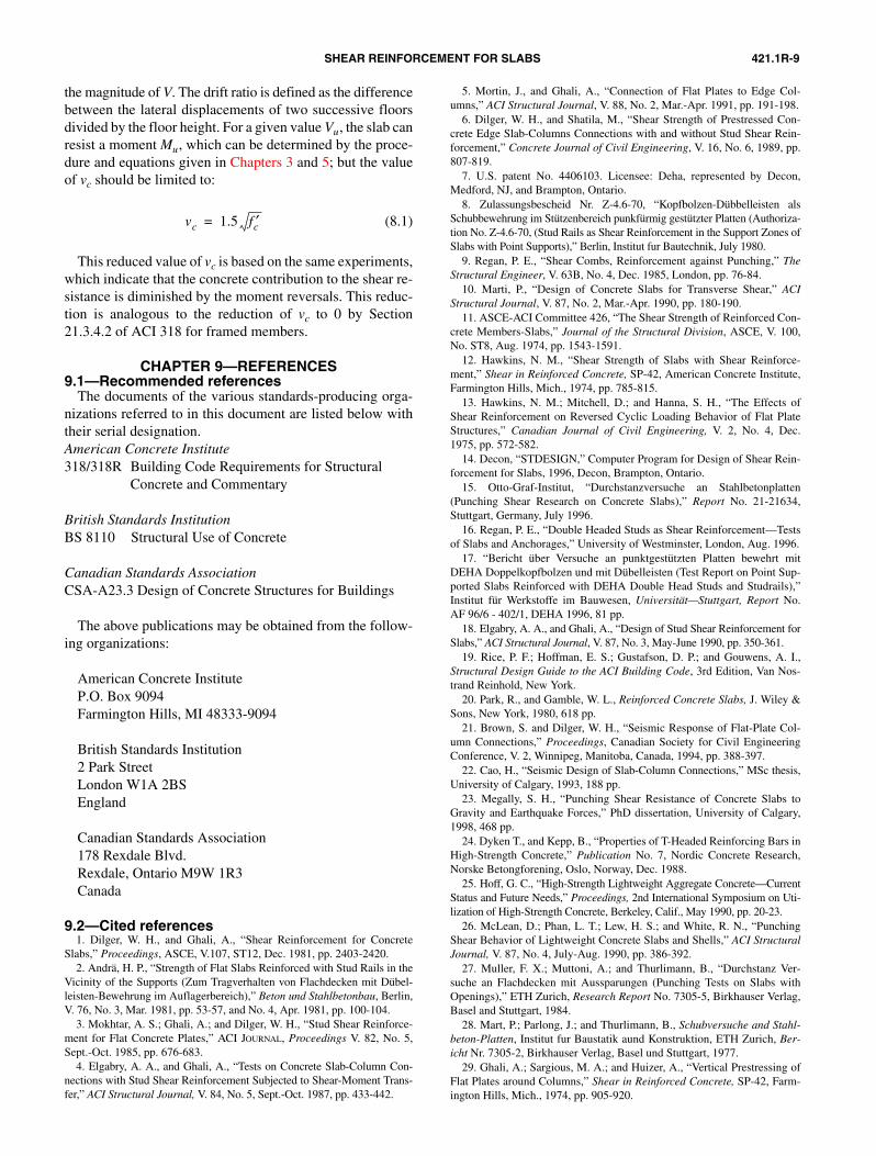
CHAPTER 9—REFERENCES9.1—Recommended references
The documents of the various standards-producing orga-nizations referred to in this document are listed below withtheir serial designation.American Concrete Institute318/318R Building Code Requirements for Structural
Concrete and Commentary
British Standards InstitutionBS 8110 Structural Use of Concrete
Canadian Standards AssociationCSA-A23.3 Design of Concrete Structures for Buildings
The above publications may be obtained from the follow-ing organizations:
American Concrete InstituteP.O. Box 9094Farmington Hills, MI 48333-9094
British Standards Institution2 Park StreetLondon W1A 2BSEngland
Canadian Standards Association178 Rexdale Blvd.Rexdale, Ontario M9W 1R3Canada
9.2—Cited references1. Dilger, W. H., and Ghali, A., “Shear Reinforcement for Concrete
Slabs,” Proceedings, ASCE, V.107, ST12, Dec. 1981, pp. 2403-2420.2. Andrä, H. P., “Strength of Flat Slabs Reinforced with Stud Rails in the
Vicinity of the Supports (Zum Tragverhalten von Flachdecken mit Dübel-leisten-Bewehrung im Auflagerbereich),” Beton und Stahlbetonbau, Berlin,V. 76, No. 3, Mar. 1981, pp. 53-57, and No. 4, Apr. 1981, pp. 100-104.
3. Mokhtar, A. S.; Ghali, A.; and Dilger, W. H., “Stud Shear Reinforce-ment for Flat Concrete Plates,” ACI JOURNAL, Proceedings V. 82, No. 5,Sept.-Oct. 1985, pp. 676-683.
4. Elgabry, A. A., and Ghali, A., “Tests on Concrete Slab-Column Con-nections with Stud Shear Reinforcement Subjected to Shear-Moment Trans-fer,” ACI Structural Journal, V. 84, No. 5, Sept.-Oct. 1987, pp. 433-442.
vc 1.5 fc′=
5. Mortin, J., and Ghali, A., “Connection of Flat Plates to Edge Col-umns,” ACI Structural Journal, V. 88, No. 2, Mar.-Apr. 1991, pp. 191-198.
6. Dilger, W. H., and Shatila, M., “Shear Strength of Prestressed Con-crete Edge Slab-Columns Connections with and without Stud Shear Rein-forcement,” Concrete Journal of Civil Engineering, V. 16, No. 6, 1989, pp.807-819.
7. U.S. patent No. 4406103. Licensee: Deha, represented by Decon,Medford, NJ, and Brampton, Ontario.
8. Zulassungsbescheid Nr. Z-4.6-70, “Kopfbolzen-Dübbelleisten alsSchubbewehrung im Stützenbereich punkfürmig gestützter Platten (Authoriza-tion No. Z-4.6-70, (Stud Rails as Shear Reinforcement in the Support Zones ofSlabs with Point Supports),” Berlin, Institut fur Bautechnik, July 1980.
9. Regan, P. E., “Shear Combs, Reinforcement against Punching,” TheStructural Engineer, V. 63B, No. 4, Dec. 1985, London, pp. 76-84.
10. Marti, P., “Design of Concrete Slabs for Transverse Shear,” ACIStructural Journal, V. 87, No. 2, Mar.-Apr. 1990, pp. 180-190.
11. ASCE-ACI Committee 426, “The Shear Strength of Reinforced Con-crete Members-Slabs,” Journal of the Structural Division, ASCE, V. 100,No. ST8, Aug. 1974, pp. 1543-1591.
12. Hawkins, N. M., “Shear Strength of Slabs with Shear Reinforce-ment,” Shear in Reinforced Concrete, SP-42, American Concrete Institute,Farmington Hills, Mich., 1974, pp. 785-815.
13. Hawkins, N. M.; Mitchell, D.; and Hanna, S. H., “The Effects ofShear Reinforcement on Reversed Cyclic Loading Behavior of Flat PlateStructures,” Canadian Journal of Civil Engineering, V. 2, No. 4, Dec.1975, pp. 572-582.
14. Decon, “STDESIGN,” Computer Program for Design of Shear Rein-forcement for Slabs, 1996, Decon, Brampton, Ontario.
15. Otto-Graf-Institut, “Durchstanzversuche an Stahlbetonplatten(Punching Shear Research on Concrete Slabs),” Report No. 21-21634,Stuttgart, Germany, July 1996.
16. Regan, P. E., “Double Headed Studs as Shear Reinforcement—Testsof Slabs and Anchorages,” University of Westminster, London, Aug. 1996.
17. “Bericht über Versuche an punktgestützten Platten bewehrt mitDEHA Doppelkopfbolzen und mit Dübelleisten (Test Report on Point Sup-ported Slabs Reinforced with DEHA Double Head Studs and Studrails),”Institut für Werkstoffe im Bauwesen, Universität—Stuttgart, Report No.AF 96/6 - 402/1, DEHA 1996, 81 pp.
18. Elgabry, A. A., and Ghali, A., “Design of Stud Shear Reinforcement forSlabs,” ACI Structural Journal, V. 87, No. 3, May-June 1990, pp. 350-361.
19. Rice, P. F.; Hoffman, E. S.; Gustafson, D. P.; and Gouwens, A. I.,Structural Design Guide to the ACI Building Code, 3rd Edition, Van Nos-trand Reinhold, New York.
20. Park, R., and Gamble, W. L., Reinforced Concrete Slabs, J. Wiley &Sons, New York, 1980, 618 pp.
21. Brown, S. and Dilger, W. H., “Seismic Response of Flat-Plate Col-umn Connections,” Proceedings, Canadian Society for Civil EngineeringConference, V. 2, Winnipeg, Manitoba, Canada, 1994, pp. 388-397.
22. Cao, H., “Seismic Design of Slab-Column Connections,” MSc thesis,University of Calgary, 1993, 188 pp.
23. Megally, S. H., “Punching Shear Resistance of Concrete Slabs toGravity and Earthquake Forces,” PhD dissertation, University of Calgary,1998, 468 pp.
24. Dyken T., and Kepp, B., “Properties of T-Headed Reinforcing Bars inHigh-Strength Concrete,” Publication No. 7, Nordic Concrete Research,Norske Betongforening, Oslo, Norway, Dec. 1988.
25. Hoff, G. C., “High-Strength Lightweight Aggregate Concrete—CurrentStatus and Future Needs,” Proceedings, 2nd International Symposium on Uti-lization of High-Strength Concrete, Berkeley, Calif., May 1990, pp. 20-23.
26. McLean, D.; Phan, L. T.; Lew, H. S.; and White, R. N., “PunchingShear Behavior of Lightweight Concrete Slabs and Shells,” ACI StructuralJournal, V. 87, No. 4, July-Aug. 1990, pp. 386-392.
27. Muller, F. X.; Muttoni, A.; and Thurlimann, B., “Durchstanz Ver-suche an Flachdecken mit Aussparungen (Punching Tests on Slabs withOpenings),” ETH Zurich, Research Report No. 7305-5, Birkhauser Verlag,Basel and Stuttgart, 1984.
28. Mart, P.; Parlong, J.; and Thurlimann, B., Schubversuche and Stahl-beton-Platten, Institut fur Baustatik aund Konstruktion, ETH Zurich, Ber-icht Nr. 7305-2, Birkhauser Verlag, Basel und Stuttgart, 1977.
29. Ghali, A.; Sargious, M. A.; and Huizer, A., “Vertical Prestressing ofFlat Plates around Columns,” Shear in Reinforced Concrete, SP-42, Farm-ington Hills, Mich., 1974, pp. 905-920.
421.1R-10 ACI COMMITTEE REPORT
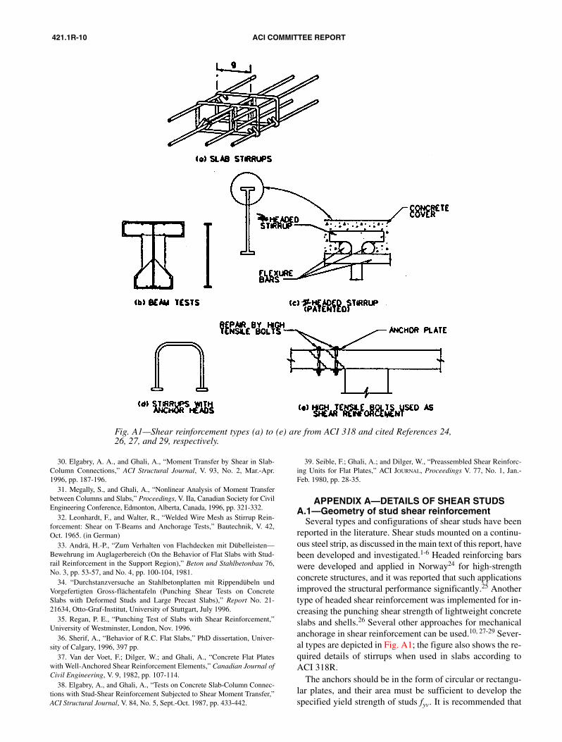
Fig. A1—Shear reinforcement types (a) to (e) are from ACI 318 and cited References 24,26, 27, and 29, respectively.
30. Elgabry, A. A., and Ghali, A., “Moment Transfer by Shear in Slab-Column Connections,” ACI Structural Journal, V. 93, No. 2, Mar.-Apr.1996, pp. 187-196.
31. Megally, S., and Ghali, A., “Nonlinear Analysis of Moment Transferbetween Columns and Slabs,” Proceedings, V. IIa, Canadian Society for CivilEngineering Conference, Edmonton, Alberta, Canada, 1996, pp. 321-332.
32. Leonhardt, F., and Walter, R., “Welded Wire Mesh as Stirrup Rein-forcement: Shear on T-Beams and Anchorage Tests,” Bautechnik, V. 42,Oct. 1965. (in German)
33. Andrä, H.-P., “Zum Verhalten von Flachdecken mit Dübelleisten—Bewehrung im Auglagerbereich (On the Behavior of Flat Slabs with Stud-rail Reinforcement in the Support Region),” Beton und Stahlbetonbau 76,No. 3, pp. 53-57, and No. 4, pp. 100-104, 1981.
34. “Durchstanzversuche an Stahlbetonplatten mit Rippendübeln undVorgefertigten Gross-flächentafeln (Punching Shear Tests on ConcreteSlabs with Deformed Studs and Large Precast Slabs),” Report No. 21-21634, Otto-Graf-Institut, University of Stuttgart, July 1996.
35. Regan, P. E., “Punching Test of Slabs with Shear Reinforcement,”University of Westminster, London, Nov. 1996.
36. Sherif, A., “Behavior of R.C. Flat Slabs,” PhD dissertation, Univer-sity of Calgary, 1996, 397 pp.
37. Van der Voet, F.; Dilger, W.; and Ghali, A., “Concrete Flat Plateswith Well-Anchored Shear Reinforcement Elements,” Canadian Journal ofCivil Engineering, V. 9, 1982, pp. 107-114.
38. Elgabry, A., and Ghali, A., “Tests on Concrete Slab-Column Connec-tions with Stud-Shear Reinforcement Subjected to Shear Moment Transfer,”ACI Structural Journal, V. 84, No. 5, Sept.-Oct. 1987, pp. 433-442.
39. Seible, F.; Ghali, A.; and Dilger, W., “Preassembled Shear Reinforc-ing Units for Flat Plates,” ACI JOURNAL, Proceedings V. 77, No. 1, Jan.-Feb. 1980, pp. 28-35.
APPENDIX A—DETAILS OF SHEAR STUDSA.1—Geometry of stud shear reinforcement
Several types and configurations of shear studs have beenreported in the literature. Shear studs mounted on a continu-ous steel strip, as discussed in the main text of this report, havebeen developed and investigated.1-6 Headed reinforcing barswere developed and applied in Norway24 for high-strengthconcrete structures, and it was reported that such applicationsimproved the structural performance significantly.25 Anothertype of headed shear reinforcement was implemented for in-creasing the punching shear strength of lightweight concreteslabs and shells.26 Several other approaches for mechanicalanchorage in shear reinforcement can be used.10, 27-29 Sever-al types are depicted in Fig. A1; the figure also shows the re-quired details of stirrups when used in slabs according toACI 318R.
The anchors should be in the form of circular or rectangu-lar plates, and their area must be sufficient to develop thespecified yield strength of studs fyv. It is recommended that
421.1R-11EMENT FOR SLABS
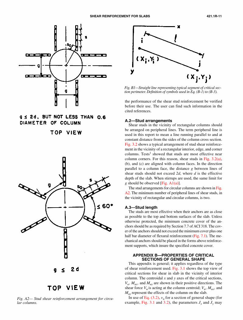
SHEAR REINFORCFig. A2— Stud shear reinforcement arrangement for circu-lar columns.
the performance of the shear stud reinforcement be verifiedbefore their use. The user can find such information in thecited references.
A.2—Stud arrangementsShear studs in the vicinity of rectangular columns should
be arranged on peripheral lines. The term peripheral line isused in this report to mean a line running parallel to and atconstant distance from the sides of the column cross section.Fig. 3.2 shows a typical arrangement of stud shear reinforce-ment in the vicinity of a rectangular interior, edge, and cornercolumns. Tests1 showed that studs are most effective nearcolumn corners. For this reason, shear studs in Fig. 3.2(a),(b), and (c) are aligned with column faces. In the directionparallel to a column face, the distance g between lines ofshear studs should not exceed 2d, where d is the effectivedepth of the slab. When stirrups are used, the same limit forg should be observed [Fig. A1(a)].
The stud arrangements for circular columns are shown in Fig.A2. The minimum number of peripheral lines of shear studs, inthe vicinity of rectangular and circular columns, is two.
A.3—Stud lengthThe studs are most effective when their anchors are as close
as possible to the top and bottom surfaces of the slab. Unlessotherwise protected, the minimum concrete cover of the an-chors should be as required by Section 7.7 of ACI 318. The cov-er of the anchors should not exceed the minimum cover plus onehalf bar diameter of flexural reinforcement (Fig. 7.1). The me-chanical anchors should be placed in the forms above reinforce-ment supports, which insure the specified concrete cover.
APPENDIX B—PROPERTIES OF CRITICAL SECTIONS OF GENERAL SHAPE
This appendix is general; it applies regardless of the typeof shear reinforcement used. Fig. 3.1 shows the top view ofcritical sections for shear in slab in the vicinity of interiorcolumn. The centroidal x and y axes of the critical sections,Vu, Mux, and Muy are shown in their positive directions. Theshear force Vu is acting at the column centroid; Vu, Mux, andMuy represent the effects of the column on the slab.
In use of Eq. (3.2), vu for a section of general shape (forexample, Fig. 3.1 and 3.2), the parameters Jx and Jy may
Fig. B1—Straight line representing typical segment of critical sec-tion perimeter. Definition of symbols used in Eq. (B-1) to (B-3).
421.1R-12 ACI COMMITTEE REPORT
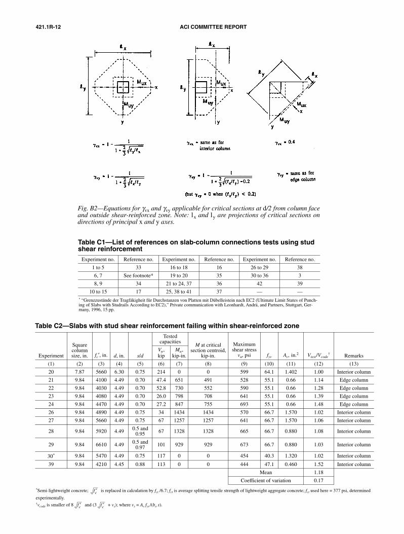
Fig. B2—Equations for γvx and γvy applicable for critical sections at d/2 from column faceand outside shear-reinforced zone. Note: lx and ly are projections of critical sections ondirections of principal x and y axes.
Table C1—List of references on slab-column connections tests using stud shear reinforcement
Experiment no. Reference no. Experiment no. Reference no. Experiment no. Reference no.
1 to 5 33 16 to 18 16 26 to 29 38
6, 7 See footnote* 19 to 20 35 30 to 36 3
8, 9 34 21 to 24, 37 36 42 39
10 to 15 17 25, 38 to 41 37 — —* “Grenzzustände der Tragfäkigheit für Durchstanzen von Platten mit Dübelleistein nach EC2 (Ultimate Limit States of Punch-ing of Slabs with Studrails According to EC2),” Private communication with Leonhardt, Andrä, and Partners, Stuttgart, Ger-many, 1996, 15 pp.
Table C2—Slabs with stud shear reinforcement failing within shear-reinforced zone
Experiment
Square column size, in. fc′, in. d, in. s/d
Tested capacities
M at critical section centroid,
kip-in.
Maximum shear stress
vu, psi fyv Av, in.2 Vtest/Vcode† Remarks
Vu , kip
Mu, kip-in.
(1) (2) (3) (4) (5) (6) (7) (8) (9) (10) (11) (12) (13)
20 7.87 5660 6.30 0.75 214 0 0 599 64.1 1.402 1.00 Interior column
21 9.84 4100 4.49 0.70 47.4 651 491 528 55.1 0.66 1.14 Edge column
22 9.84 4030 4.49 0.70 52.8 730 552 590 55.1 0.66 1.28 Edge column
23 9.84 4080 4.49 0.70 26.0 798 708 641 55.1 0.66 1.39 Edge column
24 9.84 4470 4.49 0.70 27.2 847 755 693 55.1 0.66 1.48 Edge column
26 9.84 4890 4.49 0.75 34 1434 1434 570 66.7 1.570 1.02 Interior column
27 9.84 5660 4.49 0.75 67 1257 1257 641 66.7 1.570 1.06 Interior column
28 9.84 5920 4.49 0.5 and 0.95 67 1328 1328 665 66.7 0.880 1.08 Interior column
29 9.84 6610 4.49 0.5 and 0.97 101 929 929 673 66.7 0.880 1.03 Interior column
30* 9.84 5470 4.49 0.75 117 0 0 454 40.3 1.320 1.02 Interior column
39 9.84 4210 4.45 0.88 113 0 0 444 47.1 0.460 1.52 Interior column
Mean 1.18
Coefficient of variation 0.17
*Semi-lightweight concrete; is replaced in calculation by fct /6.7; fct is average splitting tensile strength of lightweight aggregate concrete; fct used here = 377 psi, determined
experimentally.†vcode is smaller of 8 and (3 + vs); where vs = Av fyv/(bo s).
fc′
fc′ fc′

421.1R-13SHEAR REINFORCEMENT FOR SLABS
Table C3—Experiments with maximum shear stress vu at critical section of d/2 from column face
exceeding 8 (slabs with stud shear reinforcement)
ExperimentColumn size,
in.* fc′, psi 8 , psi
Tested capacities
d, in.
M at critical section centroid,
kip-in.
Maximum shear stress vu,
psi vu/8V, kip M, kip-in.
(1) (2) (3) (4) (5) (6) (7) (8) (9) (10)
1 11.81 sq. 6020 621 476 0 9.06 0 629 1.07
2 11.81 sq. 5550 589 428 0 8.86 0 585 1.00
3 11.81 sq. 3250 456 346 0 8.66 0 488 1.07
4 19.68 cr. 5550 589 665 0 10.51 0 667 1.13
5 14.57 sq. 6620 651 790 0 11.22 0 682 1.05
6 12.60 cr. 5870 613 600 0 9.33 0 934 1.52
7 12.60 cr. 6020 621 620 0 9.33 0 965 1.55
8 10.23 sq. 3120 447 271 0 8.07 0 459 1.03
9 10.23 sq. 3270 457 343 0 8.07 0 582 1.27
10 7.48 cr. 3310 460 142 0 5.83 0 582 1.26
11 7.48 cr. 3260 456 350 0 9.60 0 679 1.48
12 7.48 cr. 4610 543 159 0 6.02 0 623 1.14
13 7.48 cr. 3050 441 128 0 5.91 0 516 1.17
14 7.48 cr. 3340 462 278 0 9.72 0 530 1.14
15 7.48 cr. 3160 449 255 0 9.76 0 482 1.07
16 9.25 cr. 4630 544 207 0 5.94 0 728 1.34
17 9.25 cr. 5250 580 216 0 6.14 0 725 1.25
18 9.25 cr. 5290 582 234 0 6.50 0 725 1.24
19 7.87 sq. 5060 569 236 0 6.30 0 661 1.16
20 7.87 sq. 5660 601 214 0 6.30 0 599 1.00
21† 9.84 sq. 4100 513 47.4 651 4.49 491 528 1.03
22† 9.84 sq. 4030 508 52.8 730 4.49 552 590 1.16
23† 9.84 sq. 4080 511 26.9 798 4.49 708 641 1.25
24† 9.84 sq. 4470 535 27.2 847 4.49 755 693 1.29
25 9.84 sq. 4280 523 135 0 4.45 0 532 1.02
26 9.84 sq. 4890 559 33.7 1434 4.49 1434 570 1.02
27 9.84 sq. 5660 602 67.4 1257 4.49 1257 641 1.06
28 9.84 sq. 5920 615 67.4 1328 4.49 1328 665 1.08
29 9.84 sq. 6610 651 101 929 4.49 924 673 1.03
Mean 1.17
Coefficient of variation 0.13*Column 2 gives side dimension of square (sq.) columns or diameter of circular (cr.) columns.†Edge slab-column connections. Other experiments are on interior slab-column connections.
fc′
fc′ fc′
be approximated by the second moments of area Ix and Iy giv-en in Eq. (B-2) and (B-3). The coefficients γvx and γvy are giv-en in Fig. B2, which is based on finite element studies.30,31
The critical section perimeter is generally composed ofstraight segments. The values of Ac, Ix, and Iy can be deter-mined by summation of the contribution of the segments(Fig. 3.2):
(B-1)
(B-2)
(B-3)
Ac d l∑=
Ix d l3--- yi
2yiyj yj
2+ +( )∑=
Iy d l3--- xi
2xixj xj
2+ +( )∑=
where xi, yi , xj , and yj are coordinates of Points I and j at theextremities of the segment whose length is l (Fig. B1).
When the maximum vu occurs at a single point on the crit-ical section, rather than on a side, the peak value of vu doesnot govern the strength due to stress redistribution.21 In thiscase, vu may be investigated at a point located at a distance0.4d from the peak point. This will give a reduced vu valuecompared with the peak value; the reduction should not beallowed to exceed 15%.
APPENDIX C—VALUES OF vc WITHIN SHEAR REINFORCED ZONE
This design procedure of the shear reinforcement requirescalculation of vn = vc + vs at the critical section at d/2 fromthe column face. The value allowed for vc is 2 when stir-rups are used, and 3 when shear studs are used. The rea-son for the higher value of vc for slabs with shear stud
fc′fc′
421.1R-14 ACI COMMITTEE REPORT
Table C4—Slabs with stud shear reinforcement having s approximately equal to or greater than 0.75d
ExperimentColumn size,† in.
fc′,‡ psi d, in. s/d
Tested capacities
M at critical section centroid,
kip-in.
Maximum shear stress
vu,§ psi fyv Av, in
2(vu)outside,
|| psi Vtest/Vcode
**V, kip
M, kip-in.
(1) (2) (3) (4) (5) (6) (7) (8) (9) (10) (11) (12) (13)
3 11.81 sq. 3250 8.66 0.55 and 0.73 346 0 0 488 47.9 ? 214 1.77
12 7.48 cr. 4610 6.02 0.75 159 0 0 623 67.6 1.09 195 1.42
13 7.48 cr. 3050 5.91 0.77 128 0 0 517 67.6 1.09 160 1.43
16 9.25 cr. 4630 5.94 0.66 207 0 0 728 72.5 1.46 182 1.34
17 9.25 cr. 5250 6.14 0.65 216 0 0 725 72.5 1.46 180 1.26
18 9.25 cr. 5290 6.50 0.61 234 0 0 725 42.5 1.46 181 1.26
19 7.87 sq. 5060 6.30 0.75 236 0 0 661 54.1 1.40 165 1.08
21 9.84 sq. 4100 4.49 0.70 47.4 651 491 528 55.1 0.66 — 1.07
22 9.84 sq. 4030 4.49 0.70 52.8 730 552 590 55.1 0.66 — 1.20
23 9.84 sq. 4080 4.49 0.70 26.9 798 708 641 55.1 0.66 — 1.30
24 9.84 sq. 4470 4.49 0.70 27.2 847 755 693 55.1 0.66 — 1.38
26 9.84 sq. 4890 4.49 0.75 33.7 1434 1434 570 66.7 1.57 — 1.02
27 9.84 sq. 5660 4.49 0.75 67.4 1257 1257 641 66.7 1.57 — 1.06
30* 9.84 sq. 5470 4.49 0.75 117 0 0 454 40.3 1.32 — 1.02
31 9.84 sq. 3340 4.49 0.75 123 0 0 476 40.3 1.32 136 1.18
32 9.84 sq. 5950 4.49 0.75 131 0 0 509 70.9 1.32 145 0.94
33 9.84 sq. 5800 4.49 0.75 131 0 0 509 40.3 1.32 145 0.95
34 9.84 sq. 4210 4.49 0.75 122 0 0 473 70.9 1.32 166 1.28
35 9.84 sq. 5080 4.49 0.75 and 1.50 129 0 0 500 40.3 1.32 143 1.00
36 9.84 sq. 4350 4.49 0.75 114 0 0 444 70.9 1.32 178 1.35
38 9.84 sq. 4790 4.49 0.70 48 637 476 522 55.1 0.66 — 1.03
39 9.84 sq. 4210 4.45 0.88 113 0 0 444 47.1 0.46 — 1.52
40 9.84 sq. 4240 4.45 1.00 125 0 0 492 52.3 1.74 253 1.94
41 9.84 sq. 5300 4.45 0.88 133 0 0 523 49.2 0.99 221 1.52
42 9.84 sq. 5380 4.45 0.88 133 0 0 523 49.2 1.48 273 1.86
43 12.0 sq. 4880 4.76 1.00 134 0 0 419 73.0 1.54 270 1.93
Mean 1.31
Coefficient of variation 0.23
*Slab 30 is semi-lightweight. Concrete replaced in calculations by fct/6.7; fct average splitting tensile strength of lightweight aggregate concrete; fct used here = 377 psi, determined
experimentally.†Column 2 gives side dimension of square (sq.) columns, or diameter of circular (cr.) columns.‡For cube strengths, concrete cylinder strength in Column 3 calculated using fc′ = 0.83fcube′ .§Column 9 is maximum shear stress at failure in critical section at d/2 from column face.||(vu)outside in Column 12 is maximum shear stress at failure in critical section at d/2 outside outermost studs; (vu)outside not given for slabs that failed within stud zone.**vcode is value allowed by ACI 318 combined with proposed equations in Chapter 5. vcode calculated at d/2 from column face when failure is within stud zone and at section at d/2 from outermost studs when failure is outside shear-reinforced zone.
fc′
reinforcement is the almost slip-free anchorage of the studs.In structural elements reinforced with conventional stirrups,the anchorage by hooks or 90-deg bends is subject to slip,which can be as high as 0.04 in. when the stress in the stirrupleg approaches its yield strength.32 This slip is detrimental tothe effectiveness of stirrups in slabs because of their relativesmall depth compared with beams. The influence of the slipis manifold:• Increase in width of the shear crack;• Extension of the shear crack into the compression zone;• Reduction of the shear resistance of the compression
zone; and• Reduction of the shear friction across the crack.
All of these effects reduce the shear capacity of the con-crete in slabs with stirrups. To reflect the stirrup slip in the
shear resistance equations, refinement of the shear failuremodel is required. The empirical equation vn = vc + vs, adopt-ed in almost all codes, is not the ideal approach to solve theshear design problem. A mechanics-based model that is ac-ceptable for codes is not presently available. There is, how-ever, enough experimental evidence that use of the empiricalequation vn = vc + vs with vc = 3 gives a safe design forslabs with stud shear reinforcement. This approach is adopt-ed in Canadian code (CSA 23.3).
Numerous test slab-column connections reinforced withshear studs are reported in the literature (Table C1). In themajority of these, the failure is at sections outside the shear-reinforced zone. Table C2 lists only the tests in which thefailure occurred within the shear-reinforced zone. Column12 of Table C2 gives the ratio vtest/vcode; where vcode is the
fc′
421.1R-15SHEAR REINFORCEMENT FOR SLABS
value allowed by ACI 318, but with vc = 3 (instead of2 ). The values of vtest/vcode being greater than 1.0 indi-cate there is safety of design with .
Table C3 summarizes experimental data of numerousslabs in which the maximum shear stress vu obtained in test,at the critical section at d/2 from column face, reaches or ex-ceeds 8 . Table C3 indicates that vn can be safely takenequal to 8 (Section 5.3).
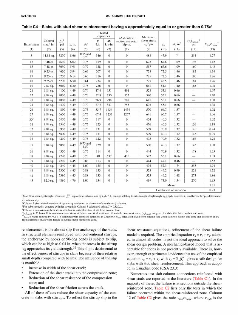
Table C4 gives the experimental results of slabs havingstud shear reinforcement with the spacing between studs
fc′fc′
vc 3 fc′=
fc′fc′
greater or close to the upper limit given by Eq. (5.1). In TableC4, vcode is the nominal shear stress calculated by ACI 318,combined with the provisions suggested in Chapter 5. Thevalue vcode is calculated at d/2 from column face when failureis within the shear-reinforced zone, or at a section at d/2 fromthe outermost studs when failure occurs outside the shear-re-inforced zone. The ratio vtest/vcode being greater than 1.0 in-dicates that it is safe to use studs spaced at the upper limit setby Eq. (5.1) and calculate the strength according to ACI 318combined with the provisions in Chapter 5.