Embed Size (px)
Citation preview
8/3/2019 amplificador jbl GTH400
http://slidepdf.com/reader/full/amplificador-jbl-gth400 1/26
GTH400-20107 06/03/98 15:49 Side 26
8/3/2019 amplificador jbl GTH400
http://slidepdf.com/reader/full/amplificador-jbl-gth400 2/26
G
T H
4 0 0
GTH400
6/ 5/ 4/ 3 CHANNEL AUTOMOTIVE POWER AMPLIFIER
OWNER’S MANUAL
GTH400-20107 06/03/98 15:49 Side 1
8/3/2019 amplificador jbl GTH400
http://slidepdf.com/reader/full/amplificador-jbl-gth400 3/26
Table of Contents1. Introduction...................................................................................... 3
1.1 Features .................................................................................... 4
1.2 About Installation ...................................................................... 4
2. Installation and use.......................................................................... 53. System Design with the GTH400..................................................... 6
3.1 Speaker Requirements ............................................................. 6
3.2 Typical Applications.................................................................. 7
4. Installation and Use ......................................................................... 9
4.1 Controls and Connectors.......................................................... 9
4.2 Internal Adjustments ................................................................ 12
Speaker-Level Input Impedance Adjustments......................... 12
Crossover Frequency Adjustments.......................................... 12
Custom Chip construction....................................................... 13
Remote Chassis Installation .................................................... 13
Unter-Dash Remote Installation............................................... 14
In-Dash remote Installation ...................................................... 14Power Supply Connections ..................................................... 14
Simultaneous Speaker Stereo-Mono Connection Diagram..... 16
Speaker-Level Input Harness - Color Codes........................... 17
5. Adjusting the Gain .......................................................................... 17
6. Important Characteristics ............................................................... 19
7. In Case of Difficulty......................................................................... 21
8. Specifications ................................................................................. 23
Owner’s Warranty InformationModel Number
Serial Number
Dealer Name
City, State, Zip
Sales Receipt Number
Date of Purchase
GTH400-20107 06/03/98 15:49 Side 2
8/3/2019 amplificador jbl GTH400
http://slidepdf.com/reader/full/amplificador-jbl-gth400 4/26
3
1. IntroductionThanks for purchasing your new GT
series automotive multichannel ampli-
fier. Your GT series amplifier will easily
connect to virtually any car audiosystem, whether it is factory installed or
one purchased separately. The GTH400
includes an abundance of unique
features which are described in this
manual. The most obvious feature of
the GTH400 is its 6-channel,
staggered-power design. This design
provides the simplicity of driving an
entire system with a single amplifier
without compromise. The flexible
design of the GTH400’s built-in
crossover circuitry also allows elaborate
systems to be built more simply than
with conventional components. For
optimum performance, the power
amplifier circuitry is a fully discrete
design notable for its low distortion and
unusually clean and clear sound quality.
In addition to conventional preamp-
level inputs, the GTH400 features JBL’s
Universal Interface design, which
facilitates simple connection to factory
radios with the low distortion that is
usually only associated with preamp
level connection. In addition, when
using a high-powered (BTL) radio
through the speaker-level inputs,
Common Sense turn-on circuitry
senses the common-mode voltage
present on the radio’s speaker wires,
turning the amplifier on without an
additional remote wire.
GTH400-20107 06/03/98 15:49 Side 3
8/3/2019 amplificador jbl GTH400
http://slidepdf.com/reader/full/amplificador-jbl-gth400 5/26
4
1.1 Features
Theory of Operation –
Virtual Center Image Enhancer
JBL’s breakthrough “Virtual Center”
circuitry is the result of theunderstanding of how the human ear
responds to timing, frequency, and
amplitude cues to determine the
apparent direction of a sound source.
Virtual Center circuitry manipulates the
analog signal in real time to provide
each of the driver’s ears with the signal
they would receive if the driver was
seated in the center of the vehicle. This
provides a stable, centered image to
the driver much like that obtained with
a dedicated center-channelloudspeaker.
To restore the spaciousness that is
generally lost in the small confines of a
car interior, the rear channels utilize
differential-mode ambience recovery to
restore the ambience information pres-
ent in all conventional stereo
recordings. Unlike DSP, the JBL
circuitry does not add synthetic reverb,
but recovers real information that is
masked in conventional systems. As a
result, the overall effect from the Virtual
Center circuitry of the GTH400 is
incredibly realistic, yet simple to adjust
and use. Best of all, the “Virtual Center”
and ambiance recovery circuits do not
require specially encoded recordings
and work with virtually all conventional
stereo tapes, discs, and broadcasts.
1.2 About Installation
Although the GTH400 is designed to
make installation as easy as possible, it
is an extremely sophisticated product
that requires proper installation andsetup to realize its full performance
potential. If you feel you do not have
the necessary knowledge and skills, we
strongly recommend that the
installation be done by your
authorized JBL dealer.
If you choose to install the GTH400
yourself, read all of the information in
this manual before you start the
installation. Pay particular attention to
the safety precautions and notes.
GTH400-20107 06/03/98 15:49 Side 4
8/3/2019 amplificador jbl GTH400
http://slidepdf.com/reader/full/amplificador-jbl-gth400 6/26
5
2. Installation and useRefer to the “Crossover Frequency
Adjustments” and “Speaker-Level Input
Impedance Adjustments” sections of
this manual to see if you will need tomake alterations to their factory
settings.
1. Disconnect the negative cable from
the battery. Note: If the vehicle’s
radio features a code type security
system, make certain you know
the code before disconnecting the
battery!
2. Run a minimum AWG #8 power
cable complete with a 60 amp fuse
(not included) directly from the
positive +12V battery terminal tothe desired amplifier location. Keep
the fuse within 6" of the battery
terminal, and position it before the
wire runs through any metal
partition.
3. Note: All wiring connections should
be made either by soldering with
heatshrink tubing insulation or with
high quality crimp-type insulated
connectors installed with a
professional-type, articulated
crimping tool. Soldering crimp-type
terminals is recommended for
additional
security. Never use wire nuts,
insulation-displacement connectors
(i.e. ScotchLok type), or twist and
tape connections. Do not use
electrical tape; it will loosen with
age and extreme temperatures.
4. Mount amplifier in the desired
location using the included screws.
5. Connect power wiring as shown in
the Wiring Diagram on page 18.
6. Connect the outputs from the head
unit to the appropriate inputs of the
amplifier according to the Wiring
Diagram (page 18) with either (or
both) high quality low-level signal
cables with RCA plugs, or the
supplied speaker-level input
connector.
7. Install the remote control in the
desired location. Connect and run
the cable from the remote to the
amplifier.
8. Connect the speakers to the ampli-
fier according to the Wiring Diagram
on page 18.
9. Turn the gain controls to the
1/4-position for all groups.
10. Set the bass boost of each group to
the desired position.
11. Set the crossover switches for each
group as desired.
12. Set the Group 2 Input and Group 3
Input as desired.
13. Set the mode switches to Stereo,
Left + Right, or Left Input Only
operation for each group.
14. Double-check your switch settings.
Reconnect the negative battery
cable. Note: Incorrect switchsettings can damage your speakers!
15. Turn on the signal source at a low
volume level, and check for the
correct output from each speaker.
16. Adjust the amplifier gain controls
using the procedure described in
the “Adjusting the Gain” section
(page 25).
17. Read the rest of the manual to get
maximum use and enjoyment from
your amplifier.
GTH400-20107 06/03/98 15:49 Side 5
8/3/2019 amplificador jbl GTH400
http://slidepdf.com/reader/full/amplificador-jbl-gth400 7/26
3. System Design Usingthe GTH4003.1 Speaker Requirements
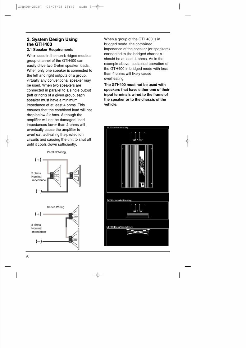
When used in the non-bridged mode a
group-channel of the GTH400 caneasily drive two 2-ohm speaker loads.
When only one speaker is connected to
the left and right outputs of a group,
virtually any conventional speaker may
be used. When two speakers are
connected in parallel to a single output
(left or right) of a given group, each
speaker must have a minimum
impedance of at least 4 ohms. This
ensures that the combined load will not
drop below 2 ohms. Although the
amplifier will not be damaged, load
impedances lower than 2 ohms will
eventually cause the amplifier to
overheat, activating the protection
circuits and causing the unit to shut off
until it cools down sufficiently.
When a group of the GTH400 is in
bridged mode, the combined
impedance of the speaker (or speakers)
connected to the bridged channels
should be at least 4 ohms. As in the
example above, sustained operation of
the GTH400 in bridged mode with less
than 4 ohms will likely cause
overheating.
The GTH400 must not be used with
speakers that have either one of their
input terminals wired to the frame of
the speaker or to the chassis of the
vehicle.
(+)
(–)
(+)
(–)
Parallel Wiring
Series Wiring
2 ohmsNominalImpedance
8 ohmsNominalImpedance
4 ohms
4 ohms
4 ohms 4 ohms
6
GTH400-20107 06/03/98 15:49 Side 6
8/3/2019 amplificador jbl GTH400
http://slidepdf.com/reader/full/amplificador-jbl-gth400 8/26
7
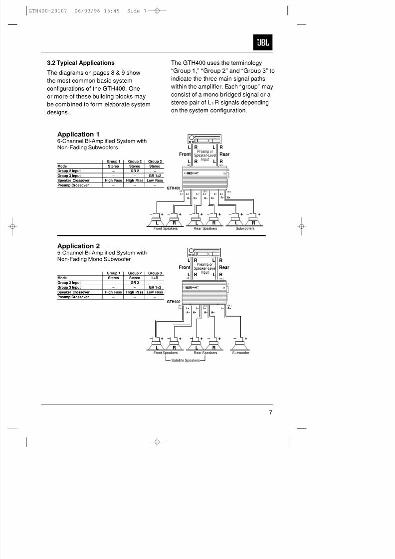
3.2 Typical Applications
The diagrams on pages 8 & 9 show
the most common basic system
configurations of the GTH400. One
or more of these building blocks maybe combined to form elaborate system
designs.
The GTH400 uses the terminology
“Group 1,” “Group 2” and “Group 3” to
indicate the three main signal paths
within the amplifier. Each “group” may
consist of a mono bridged signal or a
stereo pair of L+R signals depending
on the system configuration.
RL RL
– + – + – + – +
L+L –
R+R –
L+L – L+L –
R+R – R+R –
– + – +
Application 16-Channel Bi-Amplified System withNon-Fading Subwoofers
GTH400GR 1 GR 2
GR 1 GR 2
GR 3
RL RL RLFront Speakers Rear Speakers Subwoofers
Group 1 Group 2 Group 3
Mode Stereo Stereo Stereo
Group 2 Input – GR 2 –
Group 3 Input – – GR 1+2
Speaker Crossover High Pass High Pass Low Pass
Preamp Crossover – – –
– + – + – +
L+L –
R+R –
L+L – L –
R+R –
R+
– + – +
Application 25-Channel Bi-Amplified System withNon-Fading Mono Subwoofer
RL RLPreamp or
Speaker-LevelInput
Front Rear
RL RL
GR 1 GR 2
GR 1 GR 2
GR 3
RL RLPreamp or
Speaker-LevelInput
Front Rear
GTH400
Front Speakers
Satellite Speakers
Rear Speakers Subwoofer
Group 1 Group 2 Group 3
Mode Stereo Stereo L+R
Group 2 Input – GR 2 –
Group 3 Input – – GR 1+2
Speaker Crossover High Pass High Pass Low PassPreamp Crossover – – –
RL RL
GTH400-20107 06/03/98 15:49 Side 7
8/3/2019 amplificador jbl GTH400
http://slidepdf.com/reader/full/amplificador-jbl-gth400 9/26
8
L L RL
R+L –
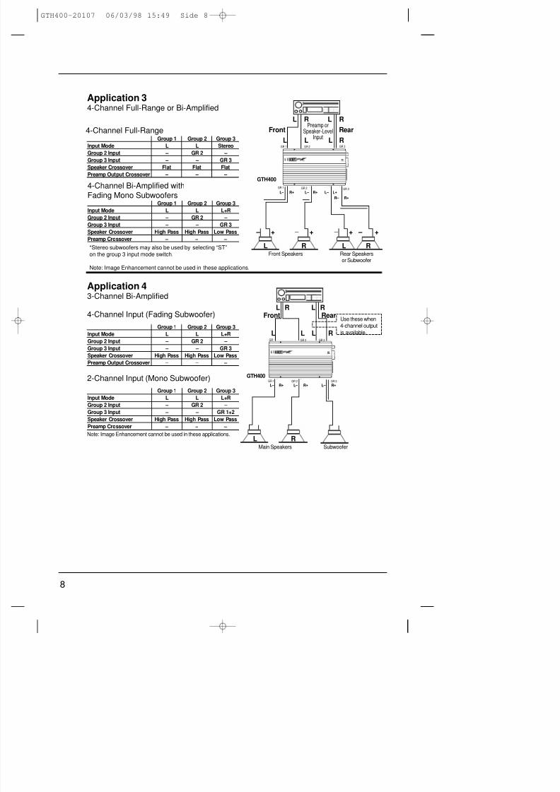
Application 43-Channel Bi-Amplified
4-Channel Input (Fading Subwoofer)L L RR
GR 1 GR 3GR 2
Group 1 Group 2 Group 3
Input Mode L L L+R
Group 2 Input – GR 2 –
Group 3 Input – – GR 3
Speaker Crossover High Pass High Pass Low Pass
Preamp Output Crossover – – –
2-Channel Input (Mono Subwoofer)
Group 1 Group 2 Group 3
Input Mode L L L+R
Group 2 Input – GR 2 –
Group 3 Input – – GR 1+2
Speaker Crossover High Pass High Pass Low Pass
Preamp Crossover – – –
L L RL
– + – + – +
R+L – R+L – L+L –
R+R –
– +
Application 34-Channel Full-Range or Bi-Amplified
Preamp orSpeaker-Level
Input
Front Rear
GTH400
GR 1 GR 2
GR 1 GR 2 GR 3
GR 3
GR 1 GR 2 GR 3
Front Speakers
Use these when
4-channel output
is available.
R+L – R+L –
GTH400
Main Speakers
Note: Image Enhancement cannot be used in these applications.
Subwoofer
Rear Speakersor Subwoofer
Group 1 Group 2 Group 3Input Mode L L Stereo
Group 2 Input – GR 2 –
Group 3 Input – – GR 3
Speaker Crossover Flat Flat Flat
Preamp Output Crossover – – –
4-Channel Bi-Amplified with
Fading Mono SubwoofersGroup 1 Group 2 Group 3
Input Mode L L L+R
Group 2 Input – GR 2 –
Group 3 Input – – GR 3
Speaker Crossover High Pass High Pass Low Pass
Preamp Crossover – – –
RL RL
Front Rear
RL
RL RL
4-Channel Full-Range
*Stereo subwoofers may also be used by selecting “ST”
on the group 3 input mode switch.
Note: Image Enhancement cannot be used in these applications.
GTH400-20107 06/03/98 15:49 Side 8
8/3/2019 amplificador jbl GTH400
http://slidepdf.com/reader/full/amplificador-jbl-gth400 10/26
9
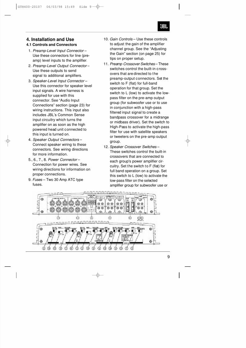
4. Installation and Use4.1 Controls and Connectors
1. Preamp-Level Input Connector –
Use these connectors for line (pre-
amp) level inputs to the amplifier.2. Preamp-Level Output Connector –
Use these outputs to send
signal to additional amplifiers.
3. Speaker-Level Input Connector –
Use this connector for speaker level
input signals. A wire harness is
supplied for use with this
connector. See “Audio Input
Connections” section (page 23) for
wiring instructions. This input also
includes JBL’s Common Sense
input circuitry which turns the
amplifier on as soon as the high
powered head unit connected to
this input is turned on.
4. Speaker Output Connectors –
Connect speaker wiring to these
connectors. See wiring directions
for more information.
5., 6., 7., 8. Power Connector –
Connection for power wires. See
wiring directions for information on
proper connections.
9. Fuses – Two 30 Amp ATC type
fuses.
10. Gain Controls – Use these controls
to adjust the gain of the amplifier
channel group. See the “Adjusting
the Gain” section (on page 25) for
tips on proper setup.
11. Preamp Crossover Switches – These
switches control the built-in cross-
overs that are directed to the
preamp-output connectors. Set the
switch to F (flat) for full-band
operation for that group. Set the
switch to L (low) to activate the low-
pass filter on the pre-amp output
group (for subwoofer use or to use
in conjunction with a high-pass
filtered input signal to create a
bandpass crossover for a midrange
or midbass driver). Set the switch toHigh-Pass to activate the high-pass
filter for use with satellite speakers
or tweeters on the pre-amp output
group.
12. Speaker Crossover Switches –
These switches control the built-in
crossovers that are connected to
each group's power amplifier cir-
cuitry. Set the switch to F (flat) for
full band operation on a group. Set
this switch to L (low) to activate the
low-pass filter on the selected
amplifier group for subwoofer use or
GTH400-20107 06/03/98 15:49 Side 9
8/3/2019 amplificador jbl GTH400
http://slidepdf.com/reader/full/amplificador-jbl-gth400 11/26
10
to use in conjunction with a high-
pass filtered input signal to create a
bandpass crossover (for a midrange
or midbass driver). Set the switch to
H (high) to activate the high-pass
filter for use with satellite speakers or
tweeters on an amplifier group.
13. Mode Switches – These switches are
used to set the input mode for both
preamp and speaker-level inputs.
Set the switch to ST(ereo) for normal
operation on the group using
individual left and right inputs. Set
this switch to L to drive both the left
and right outputs with only a single
input on the left jack. Set the switch
to L+R to sum the left and right
inputs for a mono output on thegroup. These switches do not affect
the preamp outputs.
14. Bass EQ Switch – These switches
activate a built-in Bass Boost circuit
used to increase low-bass output on
the selected group. These switches
do not effect the preamp outputs.
15. Group 2 Input Switch – This switch is
used to select which inputs will drive
Group 2 of the amplifier. Put the
switch in position “GR 1” to allow
Group 2 to be driven by the Group 1inputs. Put the switch in the “GR 2”
position to drive Group 2 with the
Group 2 inputs.
16. Group 3 Input Switch – This switch is
used to select which inputs will drive
Group 3 of the amplifier. Put the
switch in position “GR 3” to allow
Group 3 to be driven by the Group 3
inputs. Put the switch in the “GR 2”
position to drive Group 3 with the
Group 2 inputs. Put this switch in the
“GR 1+2” position to drive Group 3
with the sum of Group 1 and 2 for a
non-fading subwoofer output on
Group 3.
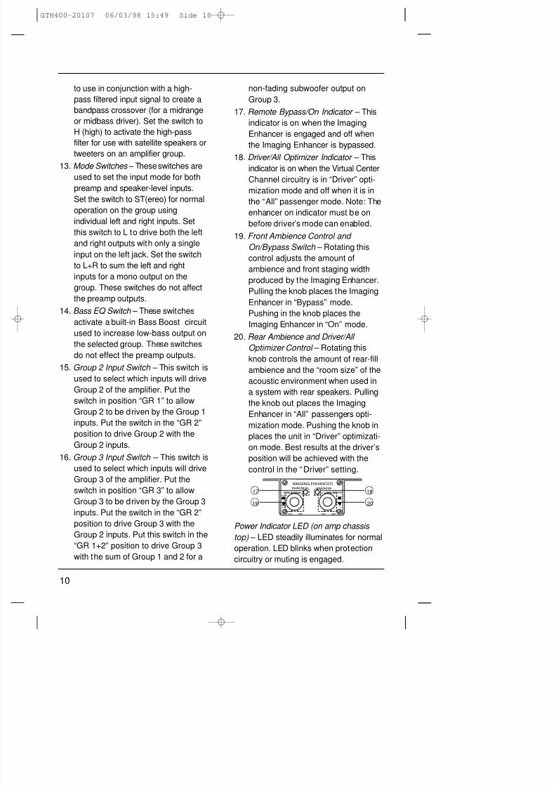
17. Remote Bypass/On Indicator – This
indicator is on when the Imaging
Enhancer is engaged and off whenthe Imaging Enhancer is bypassed.
18. Driver/All Optimizer Indicator – This
indicator is on when the Virtual Center
Channel circuitry is in “Driver” opti-
mization mode and off when it is in
the “All” passenger mode. Note: The
enhancer on indicator must be on
before driver’s mode can enabled.
19. Front Ambience Control and
On/Bypass Switch – Rotating this
control adjusts the amount of
ambience and front staging width
produced by the Imaging Enhancer.
Pulling the knob places the Imaging
Enhancer in “Bypass” mode.
Pushing in the knob places the
Imaging Enhancer in “On” mode.
20. Rear Ambience and Driver/All
Optimizer Control – Rotating this
knob controls the amount of rear-fill
ambience and the “room size” of the
acoustic environment when used in
a system with rear speakers. Pulling
the knob out places the Imaging
Enhancer in “All” passengers opti-mization mode. Pushing the knob in
places the unit in “Driver” optimizati-
on mode. Best results at the driver’s
position will be achieved with the
control in the “Driver” setting.
Power Indicator LED (on amp chassis
top) – LED steadily illuminates for normal
operation. LED blinks when protectioncircuitry or muting is engaged.
19 20
17 18
MIN MAX
BYPASS
ENHANCERON
IMAGING ENHANCERENHANCER ON DRIVERMODE
FRONT AMBIENCE REAR AMBIENCE
ALL
DRIVER
MIN MAX
GTH400-20107 06/03/98 15:49 Side 10
8/3/2019 amplificador jbl GTH400
http://slidepdf.com/reader/full/amplificador-jbl-gth400 12/26
8/3/2019 amplificador jbl GTH400
http://slidepdf.com/reader/full/amplificador-jbl-gth400 13/26
12
4.2 Internal Adjustments
Speaker-Level Input
Impedance Adjustments
The speaker level inputs of the GTH400
come factory set with 100k ohm inputimpedance. This will provide the lowest
distortion operation from the speaker
outputs of most modern head units by
reducing the power the amplifier in the
head unit must deliver to practically
nothing. On some older, or lower-priced
head units, this load will not facilitate
proper fader operation. To allow for
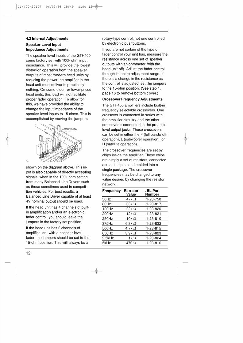
this, we have provided the ability to
change the input impedance of the
speaker-level inputs to 15 ohms. This is
accomplished by moving the jumpers
shown on the diagram above. This in-
put is also capable of directly accepting
signals, when in the 100k ohm setting,
from many Balanced Line Drivers such
as those sometimes used in competi-
tion vehicles. For best results, a
Balanced Line Driver capable of at least
4V nominal output should be used.
If the head unit has 4 channels of built-
in amplification and/or an electronic
fader control, you should leave the
jumpers in the factory set position.
If the head unit has 2 channels of
amplification, with a speaker-level
fader, the jumpers should be set to the
15-ohm position. This will always be a
rotary-type control, not one controlled
by electronic pushbuttons.
If you are not certain of the type of
fader control your unit has, measure the
resistance across one set of speakeroutputs with an ohmmeter (with the
head-unit off). Adjust the fader control
through its entire adjustment range. If
there is a change in the resistance as
the control is adjusted, set the jumpers
to the 15-ohm position. (See step 1,
page 16 to remove bottom cover.)
Crossover Frequency Adjustments
The GTH400 amplifiers include built-in
frequency selectable crossovers. One
crossover is connected in series with
the amplifier circuitry and the othercrossover is connected to the preamp
level output jacks. These crossovers
can be set in either the F (full bandwidth
operation), L (subwoofer operation), or
H (satellite operation).
The crossover frequencies are set by
chips inside the amplifier. These chips
are simply a set of resistors, connected
across the pins and molded into a
single package. The crossover
frequencies may be changed to any
value desired by changing the resistornetwork.
Frequency Resistor JBL PartValue Number
50Hz 47k Ω 1-23-750
80Hz 33k Ω 1-23-817
120Hz 22k Ω 1-23-820
200Hz 12k Ω 1-23-821
250Hz 10k Ω 1-23-810
375Hz 6.8k Ω 1-23-822
500Hz 4.7k Ω 1-23-815
650Hz 3.9k Ω 1-23-823
2.5kHz 1k Ω 1-23-824
5kHz 470 Ω 1-23-816
1 5 0 H M S
1 0 0 K
1 5 0 H M S
1 0 0 K
S P E A K E R
I N P U T
I M P E D A N C E
S E L E C T O R
L I N E I N P U T
P R E A M P O U T
1 5 0 H M S
1 0 0 K
1 5 0 H M S
1 0 0 K
JUMPERSELECTORSELECT100K OR15 OHMS
GTH400-20107 06/03/98 15:49 Side 12
8/3/2019 amplificador jbl GTH400
http://slidepdf.com/reader/full/amplificador-jbl-gth400 14/26
13
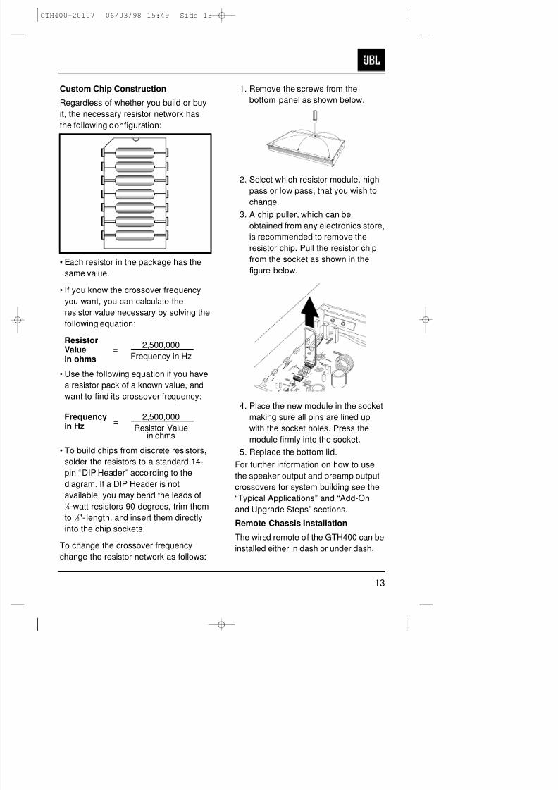
Custom Chip Construction
Regardless of whether you build or buy
it, the necessary resistor network has
the following configuration:
• Each resistor in the package has the
same value.• If you know the crossover frequency
you want, you can calculate the
resistor value necessary by solving the
following equation:
Resistor2,500,000
Value =Frequency in Hzin ohms
• Use the following equation if you have
a resistor pack of a known value, and
want to find its crossover frequency:
Frequency 2,500,000in Hz
=Resistor Value
in ohms
• To build chips from discrete resistors,
solder the resistors to a standard 14-
pin “DIP Header” according to the
diagram. If a DIP Header is not
available, you may bend the leads of1 ⁄ 4-watt resistors 90 degrees, trim them
to 1 ⁄ 8"- length, and insert them directly
into the chip sockets.
To change the crossover frequency
change the resistor network as follows:
1. Remove the screws from the
bottom panel as shown below.
2. Select which resistor module, high
pass or low pass, that you wish to
change.
3. A chip puller, which can be
obtained from any electronics store,
is recommended to remove the
resistor chip. Pull the resistor chip
from the socket as shown in the
figure below.
4. Place the new module in the socket
making sure all pins are lined upwith the socket holes. Press the
module firmly into the socket.
5. Replace the bottom lid.
For further information on how to use
the speaker output and preamp output
crossovers for system building see the
“Typical Applications” and “Add-On
and Upgrade Steps” sections.
Remote Chassis Installation
The wired remote of the GTH400 can be
installed either in dash or under dash.
H I G
H P A
S S
F I L T E R
F R E Q
U E N C Y
S E L E C T I O N
M O D
U L E
L O W
P A S S
F I L T E R
F R E Q U
E N C Y
S E L E C
T I O N
M O D
U L E
C 1 0
C 1 3
J B L I N C
.
N O R T H R
I D G
E , C
A
J B L G T S 6 0 0
P C 0 0 1 0 8 8 0 0
R E V A
C R O
S S O V E R
GTH400-20107 06/03/98 15:49 Side 13
8/3/2019 amplificador jbl GTH400
http://slidepdf.com/reader/full/amplificador-jbl-gth400 15/26
14
Under-Dash Remote Installation
1. Set the GTH400 remote in the
installation location and mark two
mounting screw hole locations.
2. Set the GTH400 remote aside anddrill two pilot holes using a 1⁄16"-
(1mm) bit. Be careful not to drill into
any of the car’s components.
3. Secure the spacer and faceplate
(with the control labeling) to the
front of the remote control panel
using the four smaller screws
included.
4. Push the two adjustment knobs
onto the metal shafts.
5. Set the GTH400 remote back in
place and secure it using two sheetmetal screws. Continue to Step 6 in
the “ In-Dash Installation” section.
In-Dash Remote Installation
1. Choose a location for the in-dash
installation and use the template at
the back of this manual to mark
hole locations as shown on the
template.
2. Drill the holes indicated on the
template.
3. Using the diagram on page 15 as
reference, install the remote behindthe panel with the holes just drilled.
Position the remote so the two
knobs feed through panel and the
LEDs are in alignment with the
holes drilled.
4. Place the trim panel with the control
labeling over the two shafts and
secure it in place with the 4 screws
provided.
5. Push the two adjustment knobs
onto the metal shafts.
6. Connect one end of the GTH400
remote control wire (included) to the
connector on the back of the
remote control box.
7. Run the wire back to the GTH400
main chassis and plug the remotecontrol wire into the “Remote In”
connector on the main chassis.
Note: a standard 6-pin telephone
extension cord may be used if more
wire is needed for remote control
connection. These extension cords
can be purchased at many
electronics or hardware stores.
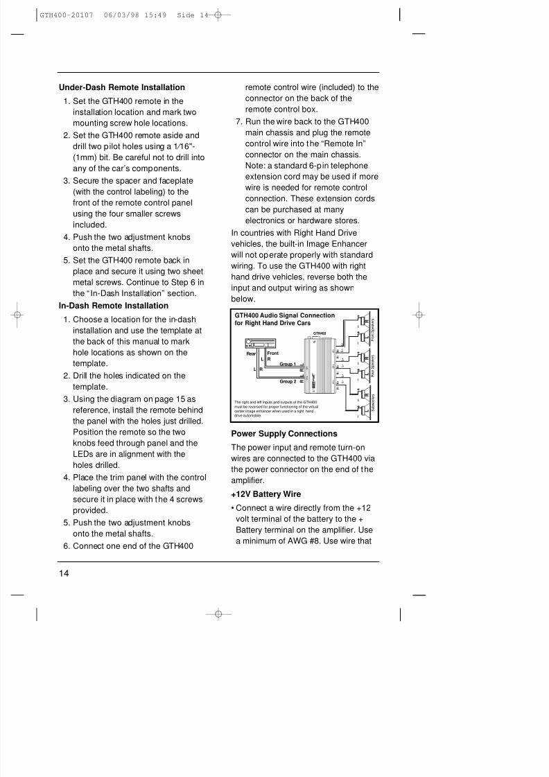
In countries with Right Hand Drive
vehicles, the built-in Image Enhancer
will not operate properly with standard
wiring. To use the GTH400 with right
hand drive vehicles, reverse both the
input and output wiring as shown
below.
Power Supply Connections
The power input and remote turn-on
wires are connected to the GTH400 via
the power connector on the end of the
amplifier.
+12V Battery Wire
• Connect a wire directly from the +12
volt terminal of the battery to the +
Battery terminal on the amplifier. Use
a minimum of AWG #8. Use wire that
L
R
L
R
–
+
–
+
–
+
–
+
R +
R –
L +
L –
R +
R –
R +
R –
L +
L –
L +
L –
–
+
–
+
GTH400
R
L
R
L
R
L F r o n t S p e a k e r s
R e a r S p e a k e r s
S u
b w o o f e r s
RL
RGroup 1
Group 2
L
FrontRear
GTH400 Audio Signal Connectionfor Right Hand Drive Cars
The right and left inputs and outputs of the GTH400
must be reversed for proper functioning of the virtualcenter image enhancer when used in a right handdrive automobile.
G R 2
G R 1
G R 3
G R 2
G R 1
GTH400-20107 06/03/98 15:49 Side 14

8/3/2019 amplificador jbl GTH400
http://slidepdf.com/reader/full/amplificador-jbl-gth400 16/26
15
FACE PLATE
DASH PANEL
SPACERPLATE (INCLUDED)
FACE PLATE
Cassette/CD Tuner CD Playeror Changer
CD Input
Cassette/CD Preamp Output
Antenna Input
Power
Antenna
Power
AntennaRelay
Blue w/White Stripe - Remote On/Off
Main +12V
Power Ground
Chassis Ground
Vehicle Battery
– +
Ignition Switch
A n t e n n a
M o t o r
P o w e r
S u p p l y
B l u e ( B l u e / W h i t e )
R
e m o t e O n / O f f
R e
m o t e A n t e n n a
B l a c k - P o w e r G r o u n d
R e d
- M a i n + 1 2 V
Y e l l o w - B a c k U p P o w e r
F u s e
F u s e
Fuse
Cassette/ReceiverPower Supply
Wires
Speakers
+
–
+
Speakers
+
–
+
Speakers
+
–
+
60 Amp(Not Included)
AmplifierPower
Connection
AmplifierSpeakerOutputConnection
AmplifierSpeakerOutputConnection
AmplifierSpeakerOutputConnection
AmplifierSpeaker
LevelInputs
Cassette/CD TunerSpeaker Level Output Connection(Use only when line level ouputis not available)
IMAGINGENHANCER
GTH400-20107 06/03/98 15:49 Side 15
8/3/2019 amplificador jbl GTH400
http://slidepdf.com/reader/full/amplificador-jbl-gth400 17/26
16
is heat- and oil-resistant whenever
running wires through the engine
compartment. All wire-to-wire
connections should be soldered and
insulated with heat shrink tubing, or
connected through a high-quality
insulated crimp-on connector or
secure set-screw-type terminal
blocks. Never leave bare wire
exposed. Terminate wires with crimp-
or solder-on lug terminals whenever
appropriate.
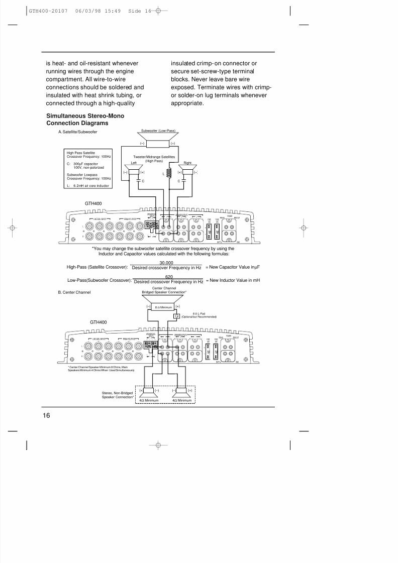
High Pass SatelliteCrossover Frequency: 100Hz
C: 300µF capacitor100V, non-polorized
Subwoofer LowpassCrossover Frequency: 100Hz
L: 6.2mH air core inductor
(+)
(+)
(–)
(–)(+)(–)
C
Subwoofer (Low-Pass)
Tweeter/Midrange Satellites(High Pass)
RightLeft
C
L
POWER
BATT(+)
REM OUTREM IN
GND
SPEAKERLEVELINPUTS
FUSE30A
FUSE30A
_ _ _ _
++L 1 R L 2 R L 3 R
++ ++
L
R+ – – +
+ – – +R 2 L
R 1 L
+
–
1 2 3 1 2 3
LINE LEVEL INPUTS PREAM POUTPUTS
SPEAKEROUTPUTS
3 0 A
3 0 A
GTH400
A. Satellite/Subwoofer
POWER
BATT(+)
REM OUTREM IN
GND
SPEAKERLEVELINPUTS
FUSE30A
FUSE30A
_ _ _ _
++L 1 R L 2 R L 3 R
++ ++
L
R+ – – +
+ – – +R 2 L
R 1 L
+
–
1 2 3 1 2 3
LINE LEVEL INPUTS PREAM POUTPUTS
SPEAKEROUTPUTS
3 0 A
3 0 A
Stereo, Non-BridgedSpeaker Connection*
Center ChannelBridged Speaker Connection*
* Center Channel Speaker Minimum 8 Ohms, MainSpeakers Minimum 4 Ohms When Used Simultaneously.
8 Ω L-Pad(Optional but Recommended)
4Ω Minimum 4Ω Minimum
GTH400
( + ) ( – )
( + ) ( + ) ( – ) ( – )
8 Ω Minimum
B. Center Channel
*You may change the subwoofer satellite crossover frequency by using theInductor and Capacitor values calculated with the following formulas:
High-Pass (Satellite Crossover): = New Capacitor Value in µF
Low-Pass(Subwoofer Crossover): = New Inductor Value in mH
30,000Desired crossover Frequency in Hz
620Desired crossover Frequency in Hz
Simultaneous Stereo-MonoConnection Diagrams
GTH400-20107 06/03/98 15:49 Side 16
8/3/2019 amplificador jbl GTH400
http://slidepdf.com/reader/full/amplificador-jbl-gth400 18/26
17
• The GTH400 will draw as much as 60
amps from the vehicle’s electrical
system, enough to overload
conventional vehicle wiring. Therefore
the +12 volt power supply must be
taken directly from the positive side of
the battery.
Do not connect to the vehicle’s fuse
block or to a wire feeding other
accessories.
• To prevent electrical system damage
or fire, a fuse holder and fuse (not
included – maximum 60 Amp) must be
installed in the power supply wire as
close to the battery as possible, and
before the wire travels through the
firewall or other metal panel.Ground Wire
• Proper grounding is extremely
important. Use a heat- and oil-
resistant stranded copper automotive
wire equivalent to the size used for the
+12V connection. Crimp or solder and
insulate any wire-to-wire connections.
Keep the ground wire as short as
possible. A ground wire must be
solidly connected to a major sheet
metal structure of the vehicle such as
a panel near the amp-mountinglocation. Scrape all paint and primer
off the sheet metal at the grounding
point to ensure a good electrical
connection. Attach the wire to the
grounding point with a nut, bolt and
star washer. The high current
demanded by high-powered amplifiers
requires a more secure ground than
the typical sheet-metal screw will
provide.
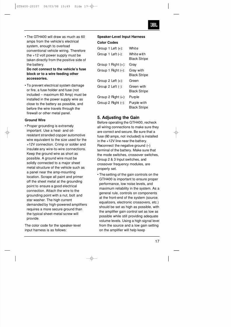
The color code for the speaker-level
input harness is as follows:
Speaker-Level Input Harness
Color Codes
Group 1 Left (+): White
Group 1 Left (–): White with
Black Stripe
Group 1 Right (+): Gray
Group 1 Right (–): Gray with
Black Stripe
Group 2 Left (+): Green
Group 2 Left (–): Green with
Black Stripe
Group 2 Right (+): Purple
Group 2 Right (–): Purple with
Black Stripe
5. Adjusting the GainBefore operating the GTH400, recheck
all wiring connections to make sure they
are correct and secure. Be sure that a
fuse (60 amps, not included) is installed
in the +12V line near the battery.
Reconnect the negative ground (–)
terminal of the battery. Make sure that
the mode switches, crossover switches,
Group 2 & 3 Input switches, and
crossover frequency modules, are
properly set.
• The setting of the gain controls on the
GTH400 is important to ensure proper
performance, low noise levels, and
maximum reliability in the system. As a
general rule, controls on components
at the front-end of the system (source,
equalizers, electronic crossovers, etc.)
should be set as high as possible, with
the amplifier gain control set as low as
possible while still providing adequate
volume levels. Using a high signal level
from the source and a low gain setting
on the amplifier will help keep
GTH400-20107 06/03/98 15:49 Side 17
8/3/2019 amplificador jbl GTH400
http://slidepdf.com/reader/full/amplificador-jbl-gth400 19/26
18
background noise levels in the system
low.
• To adjust a system using a single
GTH400, start with all three of the
amplifier gain controls fullycounterclockwise and the Imaging
Enhancer Remote set to “Bypass”
mode. Some head units have
additional output level controls or
switches. Set those to their maximum
position.
• Set the level controls on any
associated equipment such as
equalizers and electronic crossovers
as recommended by their
manufacturers. Set all Bass/ Treble or
equalizer controls to their centered orbypassed positions. While listening
carefully to the system output, adjust
the volume control of the radio/tape
deck to the point where you first begin
to hear audible distortion. Use caution:
excessive distortion can damage
loudspeakers. Reduce the level just to
the point where the distortion goes
away. This is the maximum
undistorted output level of your head
unit and signal processors, and should
not be exceeded during use. If audibledistortion does not occur, continue to
increase the level until the head unit is
turned all the way up. If this setting
does not provide adequate volume
levels, gradually increase (turn
clockwise) the gain control for the
main (usually front) speaker groups on
the GTH400 until the system plays as
loud as necessary or when the first
signs of distortion are heard.
• After adjusting the main speaker’s
gain control, you may then turn down
the head unit’s volume control to a
comfortable level, and adjust the
remaining channels for the desired
system balance. You will find this
easiest to do by adjusting the
channels in the following order: 1)
front speaker Group, 2) rear speaker
Group, 3) subwoofer speaker Group.
Elaborate systems incorporating tri- or
quad-amplification can be complex to
adjust. Your local authorized JBL
installation specialist is the best
person to help with such adjustment.
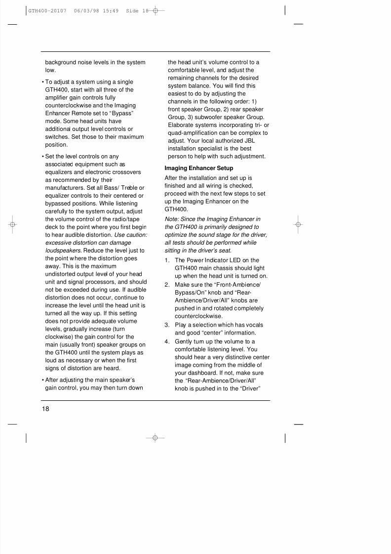
Imaging Enhancer Setup
After the installation and set up is
finished and all wiring is checked,
proceed with the next few steps to setup the Imaging Enhancer on the
GTH400.
Note: Since the Imaging Enhancer in
the GTH400 is primarily designed to
optimize the sound stage for the driver,
all tests should be performed while
sitting in the driver’s seat.
1. The Power Indicator LED on the
GTH400 main chassis should light
up when the head unit is turned on.
2. Make sure the “Front-Ambience/
Bypass/On” knob and “Rear-Ambience/Driver/All” knobs are
pushed in and rotated completely
counterclockwise.
3. Play a selection which has vocals
and good “center” information.
4. Gently turn up the volume to a
comfortable listening level. You
should hear a very distinctive center
image coming from the middle of
your dashboard. If not, make sure
the “Rear-Ambience/Driver/All”
knob is pushed in to the “Driver”
GTH400-20107 06/03/98 15:49 Side 18
8/3/2019 amplificador jbl GTH400
http://slidepdf.com/reader/full/amplificador-jbl-gth400 20/26
19
position for driver-opt imized sound
stage.
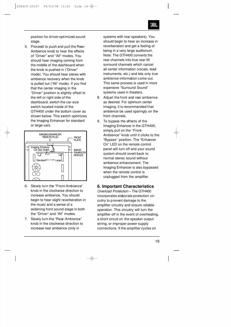
5. Proceed to push and pull the Rear-
Ambience knob to hear the effects
of “Driver” and “All” modes. Youshould hear imaging coming from
the middle of the dashboard when
the knob is pushed in (“Driver”
mode). You should hear stereo with
ambience recovery when the knob
is pulled out (“All” mode). If you find
that the center imaging in the
“Driver” position is slightly offset to
the left or right side of the
dashboard, switch the car-size
switch located inside of the
GTH400 under the bottom cover as
shown below. This switch optimizes
the Imaging Enhancer for standard
or large cars.
6. Slowly turn the “Front-Ambience”
knob in the clockwise direction to
increase ambience. You should
begin to hear slight reverberation in
the music and a sense of a
widening front sound stage in both
the “Driver” and “All” modes.
7. Slowly turn the “Rear-Ambience”
knob in the clockwise direction to
increase rear ambience (only in
systems with rear speakers). You
should begin to hear an increase in
reverberation and get a feeling of
being in a very large auditorium.
Note: The GTH400 converts the
rear channels into true rear-fill
surround channels which cancel
all center information (vocals, lead
instruments, etc.) and lets only true
ambience information come out.
This same process is used in more
expensive “Surround Sound”
systems used in theaters.
8. Adjust the front and rear ambience
as desired. For optimum center
imaging, it is recommended that
ambience be used sparingly on the
front channels.
9. To bypass the effects of the
Imaging Enhancer in the GTH400,
simply pull on the “Front-
Ambience” knob until it clicks to the
“Bypass” position. The “Enhancer
On” LED on the remote control
panel will turn off and your sound
system should revert back to
normal stereo sound without
ambience enhancement. The
Imaging Enhancer is also bypassed
when the remote control isunplugged from the amplifier.
6. Important CharacteristicsOverload Protection – The GTH400
incorporates elaborate protection cir-
cuitry to prevent damage to the
amplifier circuitry and ensure reliable
operation. This circuitry will turn the
amplifier off in the event of overheating,
a short circuit on the speaker output
wiring, or improper power supply
connections. If the amplifier cycles on
IMAGEENHANCERMODULE
FRONTPLATE
IMAGING ENHANCERREMOTE PLUG
Standard Large
Imaging EnhancerCar Size Switch
GTH400-20107 06/03/98 15:50 Side 19

8/3/2019 amplificador jbl GTH400
http://slidepdf.com/reader/full/amplificador-jbl-gth400 21/26
20
and off, or does not work at all, a
problem in installation or an abnormal
electrical condition is indicated. Check
speaker wiring for short c ircuits or
impedance loads significantly below 2
ohms (4 ohms in bridged mode). Check
the power supply voltage at the input of
the amplifier to be sure that it is normal;
between 11 and 16 volts. Check that
the power wires are not reversed.
GTH400-20107 06/03/98 15:50 Side 20
8/3/2019 amplificador jbl GTH400
http://slidepdf.com/reader/full/amplificador-jbl-gth400 22/26
21
7. In Case of DifficultyPower-on light does not come on • Head unit not on; turn the head unit on.
• Ground wire is disconnected or
defective; check for continuity with an
ohmmeter between the amplifier’sground terminal and a known chassis
ground point.
• Battery wire is disconnected or
defective; check for approximately +12
volts between the amplifier’s battery and
ground terminals.
• Blown fuse; check amplifier’s fuses
located on the end panel near the power
connector. If they are blown, replace
them with an identical one. If the new
fuses blow immediately, then check all
the wiring connections. If no fault isfound, consult your JBL dealer.
• Remote-on wire between the head unit
and the amplifiers is disconnected or
defective; check for +12 volts between
amplifiers remote-on input terminal and
the ground wire with the head unit on.
Power light is on, but no sound is heard • Incorrect switch settings; make sure
from some or all of the speakers that all switches (mode, input and
crossover) are in their correct positions
for your system configuration.
• Incorrectly connected or shorted
speaker wires; check for shorts in
wiring.
• Defective or disconnected audio cables;
check for continuity and replace if
necessary.
• Incorrect gain adjustment; verify that the
amplifier gain controls are not turned
completely down. If they are, sound
output level may be very low and may
give the impression that the system (or
part of the system) is dead.
GTH400-20107 06/03/98 15:50 Side 21
8/3/2019 amplificador jbl GTH400
http://slidepdf.com/reader/full/amplificador-jbl-gth400 23/26
22
Power light is on, but no sound is heard • Defective head unit or signal processor;
from some or all of the speakers check each component for proper wiring
and operation.
• Defective GTH400; If there is audio
signal present at the inputs of theamplifier and there is no output, the
GTH400 may be defective.
Alternator whine through the audio system • Ground loops; follow the wiring
with the engine running suggestions in the section called
“Solving Noise Problems.” Also, verify
that the chassis grounding point you
have chosen is true ground by checking
for cont inuity between the chassis
ground point and battery ground.
Bass output from speakers too low • Speaker wired out of phase; check for
proper polarity on all speaker wiring
(+ amp terminal to + speaker terminaland – amp terminal to – speaker
terminal).
Amplifier Power Light is on and • Verify that the remote control is not set
sound is heard from the front and rear in “BYPASS” mode by checking to see
channels but the Imaging is not improved that the “ON” LED is lit.
with the image enhancer on • Using the system configuration diagram,
confirm that the audio connections are
correct for signal path and polarity. Note
that right hand drive car installations
must have the Left and Right input and
output connections reversed as shown in
the wiring section on page 19.
• Perform the adjustments as directed in
the Imaging Enhancer Setup section.
Power light is blinking and • Incorrectly connected or shorted speaker
no sound is heard wires; check for shorts in wiring.
• Defective GTH400; if there is no short
on the speaker outputs, the GTH400
may be broken. Consult your JBL dealer.
GTH400-20107 06/03/98 15:50 Side 22
8/3/2019 amplificador jbl GTH400
http://slidepdf.com/reader/full/amplificador-jbl-gth400 24/26
23
8. SpecificationsGTH400
35 Watts x 4 + 70 Watts x 2 (4 ohms, 0.05% THD)
50 Watts x 4 + 100 Watts x 2 (2 ohms, 0.08% THD)
100 Watts x 2 (Bridged 4 ohms, 0.08% THD) +
70 Watts x 2 (4 ohms, 0.05% THD)
100 Watts x 2 (Bridged 4 ohms, 0.08% THD) +
200 Watts x 1 (Bridged 4 ohms, at 0.08% THD)
Signal to Noise Ratio 100dBA
Frequency Response 10Hz – 50kHz (+0, –1dB)
20Hz – 20kHz (+0, –0.1dB)
Damping Factor >200
Slew Factor >5
Line Level Input Sensit ivity 100mV – 4V RMS
(For Rated Power)
Line Level Input Impedance 10k ohms
Speaker Level Input Impedance 15 ohm or 100k ohm
(Selectable by Internal Jumpers)
Speaker Level Input Sensitivity 200mV – 8V RMS
Preamp Output Sensitivity
Preamp Input: 4V in for 4V out
Speaker Input: 4V in for 2V out
Minimum Speaker Impedance
Single Ended (Non-Bridged) 2 ohms
Bridged 4 ohms
Built- in Electronic 18dB per Octave Low-Pass Filter,
Crossover Frequency and Slope Frequency Chips Available from 50–5kHz
Factory Setting 80Hz
18dB per Octave High-Pass Filter,
Frequency Chips Available from 50–5kHz
Bass Boost Frequency +4dB at 40Hz
and Magnitude
GTH400-20107 06/03/98 15:50 Side 23
8/3/2019 amplificador jbl GTH400
http://slidepdf.com/reader/full/amplificador-jbl-gth400 25/26
24
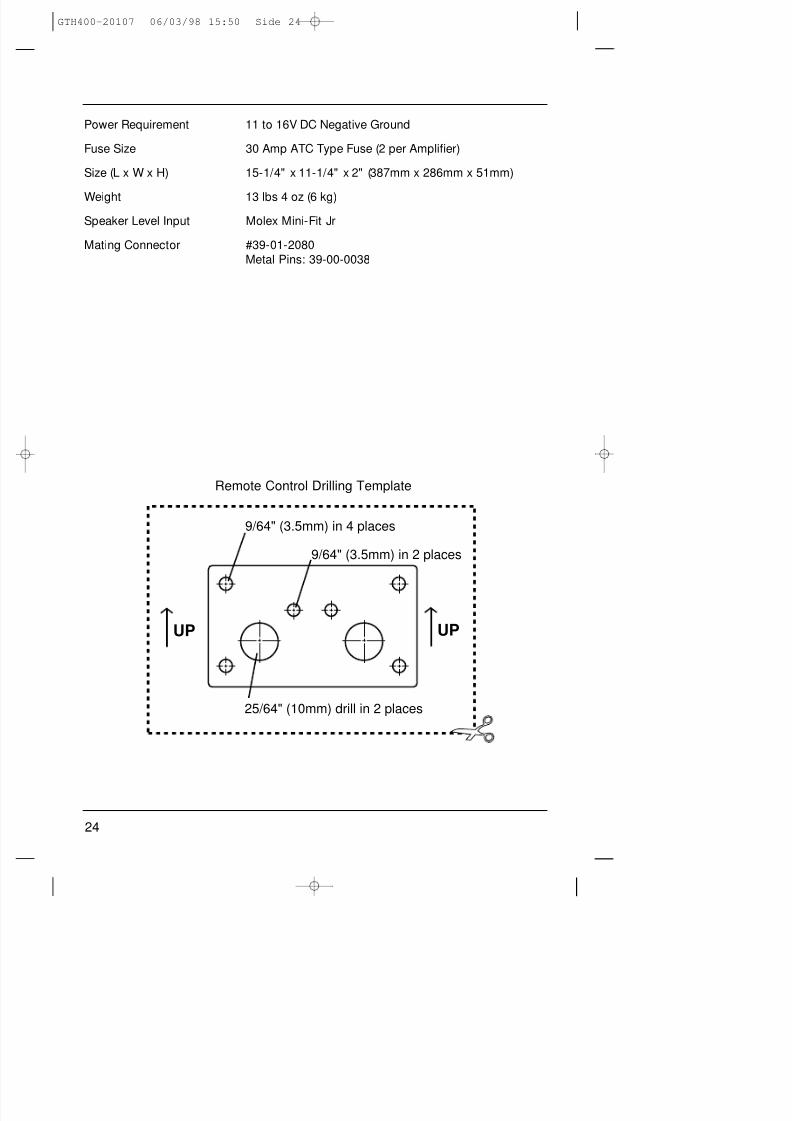
9/64" (3.5mm) in 4 places
9/64" (3.5mm) in 2 places
25/64" (10mm) drill in 2 places
UP UP
Remote Control Drilling Template
Power Requirement 11 to 16V DC Negative Ground
Fuse Size 30 Amp ATC Type Fuse (2 per Amplifier)
Size (L x W x H) 15-1/4" x 11-1/4" x 2" (387mm x 286mm x 51mm)
Weight 13 lbs 4 oz (6 kg)
Speaker Level Input Molex Mini-Fit Jr
Mating Connector #39-01-2080
Metal Pins: 39-00-0038
GTH400-20107 06/03/98 15:50 Side 24

8/3/2019 amplificador jbl GTH400
http://slidepdf.com/reader/full/amplificador-jbl-gth400 26/26


![[JBL S3900] JBL 가문에서 출중한 미인이 탄생하다 - 월간오디오](https://img.pdfslide.tips/doc/110x75/568c36b21a28ab0235990729/jbl-s3900-jbl-.jpg)