Embed Size (px)
Citation preview
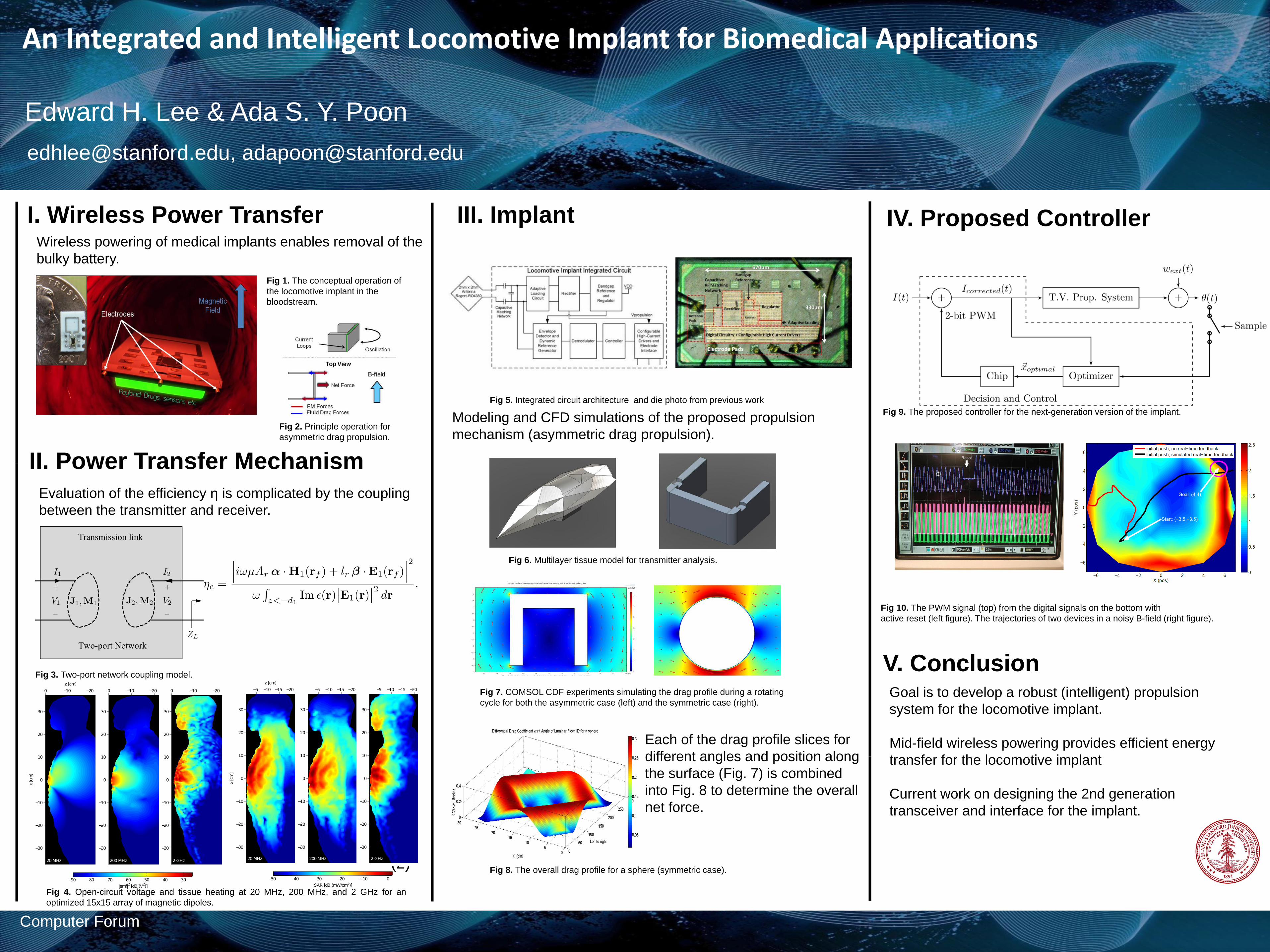
An Integrated and Intelligent Locomotive Implant for Biomedical Applications
Edward H. Lee & Ada S. Y. Poon
[email protected], [email protected]
Computer Forum
I. Wireless Power Transfer Wireless powering of medical implants enables removal of the
bulky battery.
Fig 1. The conceptual operation of
the locomotive implant in the
bloodstream.
III. Implant
II. Power Transfer Mechanism
Evaluation of the efficiency η is complicated by the coupling
between the transmitter and receiver.
IV. Proposed Controller
Fig 3. Two-port network coupling model.
(2)
Fig 10. The PWM signal (top) from the digital signals on the bottom with
active reset (left figure). The trajectories of two devices in a noisy B-field (right figure).
Goal is to develop a robust (intelligent) propulsion
system for the locomotive implant.
Mid-field wireless powering provides efficient energy
transfer for the locomotive implant
Current work on designing the 2nd generation
transceiver and interface for the implant.
V. Conclusion
Fig 4. Open-circuit voltage and tissue heating at 20 MHz, 200 MHz, and 2 GHz for an
optimized 15x15 array of magnetic dipoles.
Fig 7. COMSOL CDF experiments simulating the drag profile during a rotating
cycle for both the asymmetric case (left) and the symmetric case (right).
Fig 2. Principle operation for
asymmetric drag propulsion.
Fig 5. Integrated circuit architecture and die photo from previous work
Modeling and CFD simulations of the proposed propulsion
mechanism (asymmetric drag propulsion).
Fig 6. Multilayer tissue model for transmitter analysis.
Fig 8. The overall drag profile for a sphere (symmetric case).
Each of the drag profile slices for
different angles and position along
the surface (Fig. 7) is combined
into Fig. 8 to determine the overall
net force.
Fig 9. The proposed controller for the next-generation version of the implant.