Embed Size (px)
Citation preview

)م2004 أبريل / هـ1425 صفر (المدينة المنورة، جامعة الملك عبدالعزيز ، ) المعلوماتية في خدمة ضيوف الرحمن(المؤتمر الوطني السابع عشر للحاسب اآللي
155
An Interactive Software for the Design of Riveted Joints
Haitham A. Bogis, Ali Abou Ezz, Abdulmalik A. Aljinaidi and Mehmet Akyurt
Mechanical Engineering Dept., KAAU, Jeddah 21589 Correspondence: [email protected]
ABSTRACT. An educational software package; Seam Rivets, is introduced for the analysis and design of riveted joints. The user starts the application by selecting an objective from among five alternatives; to determine the safety of a given riveted joint, the rivet diameter for a specific loading and plate geometry, the plate width and thickness, and the diameter of the rivet for a given loading. Alternatively, he may opt to determine the number of rivets needed. In all five cases, the user is prompted to select between lap and butt type of joint, and to specify the type of head for the rivet. Fulfilling of some of the objectives requires the description of the geometry of the joint and all involved parts, the specification of the materials unless the use of the default material is acceptable. Invoking next; the solve command, the software carries out a series of tedious computations, after which it presents a comprehensive report comprising a summary of stresses, Joint efficiency and factors of safety, and a detailed summary of the joint geometry and properties.
1. Introduction
A rivet is a short cylindrical bar with a head integral with it. Rivets are used to make permanent fastening between two or three plates. Conventional structural rivets are widely used in aircraft, transportation equipment, and other products requiring high joint strength. They are also used in the construction of buildings, boilers, bridges, and ships, but in recent decades these applications have made increasing use of welding. Because of vital safety considerations, the design of riveted connections for these latter applications is governed by construction codes. Significant initial tension is attainable in rivets by installing them at a red heat. The tension develops upon cooling and thermal contraction.
Whereas the development of modern welding equipment has reduced the importance of rivets for heavy structural applications, the development of modern riveting machines has greatly expanded their use in fastening smaller components in a multitude of industrial products associated with the automotive, appliance, electronic, furniture, business machine, and other fields. Rivets have frequently replaced threaded fasteners in these applications because of lower installation cost. Rivets are much cheaper than bolts, and modern high-speed riveting machines - some of which fasten over 1000 assemblies per hour - give low assembly cost. Rivets can also serve as pivot shafts (as in folding lawn furniture), electrical contacts, stops, and inserts.
156
In comparison with threaded fasteners, rivets are not susceptible to unintended
loosening, but in some cases they impede desired disassembly and servicing. On the other hand, making an electrical device so that it cannot be disassembled and tampered with by the layman may constitute a safety feature.
Rivets can be made from most ductile material, with carbon steel, aluminum, brass and
copper being most commonly used. Various platings, paints, and oxide coatings may be applied. In general, a rivet cannot provide as strong an attachment as a bolt or screw of the same diameter. As with bolts, care must be taken in selecting materials to be used together because of possible galvanic action.
Industrial rivets are of two basic types: tubular, and blind. Each type comes in a
multitude of varieties. The semitubular version is the most common. Self-piercing rivets make their own holes as they are installed by a riveting machine. Full tubular rivets (Fig. 1) are generally used for leather, plastics, wood, fabric, or other soft materials. Bifurcated, or split, rivets can be used to join light-gage metals. Metal-piercing rivets can fasten metals like steel and aluminum with hardnesses up to about RB 50 (approximately 93 Bhn). Blind rivets require access to only one side of the joint.
Compression rivets are made in two parts, as shown in Fig. 1c. The diameters are
selected to provide an appropriate interference fit at each interface. Compression rivets can be used with wood, brittle plastics, or other materials with little danger of splitting during setting (installation). One common application is in the cutlery field, where the flush surfaces and interference fits provide no crevices for food and dirt particles to accumulate, as in riveted knife handles.
Current research on riveted joints seems to be concentrated on non-destructive testing,
corrosion, analytical and numerical modeling and testing of rivets and rivet holes, nucleation of cracks and stress intensity factors, fretting and fatigue failure, shear failure, and the riveting
Fig. (1) : Types of rivets [1].

157
of composites. Lap joints receive much attention, especially as related to aircraft structures. Below we summarize a small portion of current research efforts related to riveting.
Maskow [2] reported that “the first successful beginnings towards rationalizig and
humanizing” the structural assembly of civil aircraft, in this particular case in the production of riveted joints, have currently been made: A riveting system for spherically shaped aircraft frame structures has been specified, projected and tested for the assembly of aircraft shells. He described a 5-axis-CNC riveting equipment, in which an optical sensor system provides the possibility of compensating variations automatically by means of component tolerances.
Jarfall [3] made an attempt to review the state-of-the-art in procedures for designing and
optimizing bolted or riveted joints. Methods and data desired for the design procedure were defined and compared with what is available to day. Following major steps in the design procedure were covered: Calculation of the force distribution in the joint, which requires methods and data to account for fastener flexibility, eccentricities and bending support from surrounding structure; Calculation of the fatigue quality or the fatigue life, which requires that the influence from bypass stress, load transfer and secondary bending on the fatigue performance must be known for various combinations of material qualities (of the joined members), hole qualities and fastener types.
Onjukka [4] noted that corrosion, due to its insidious nature, has become one of the major
issues among commercial air craft. All operators of heavy aircraft are now required to inspect, repair and apply corrosion-inhibiting compounds to all metallic primary structures. In this connection, a preliminary study was conducted by the author to determine the fatigue life or resistance to corrosion of welded or riveted joints. He found that welded coupons exhibited a longer fatigue life than riveted coupons. Based on the results, he recommended that design improvements can extend and improve the corrosion resistance of aircraft.
Gaul and Lenz [5] remarked that the nonlinear transfer behaviour of an assembled
structure such as a large lightweight space structure is caused by the nonlinear influence of structural connections. Accordingly, bolted or riveted joints are the primary source of damping compared to material damping, if no special damping treatment is added to the structure. Simulation of this damping amount would be important in the design phase of a structure. Several well known lumped parameter joint models used in the past to describe the dynamic transfer behaviour of isolated joints by Coulomb friction elements are capable of describing global states of slip and stick only. The authors investigated the influence of joints by a mixed experimental and numerical strategy. A detailed Finite Element model was established to provide understanding of different slip-stick mechanisms in the contact area. A lumped parameter model was developed and identified by experimental investigations for an isolated bolted joint.
Casu et al. [6] studied the structural behavior of a riveted joint during cooling after hot
heading. They found that the semi-empirical formulation used for this purpose cannot justify the strength of the joint. They established that stresses inside the rivet and the jointed elements are lower than the yield point, differently from previous calculations.
Patronelli et al. [7] remarked that numerous kinds of rivets have to be modelled for
simulation of aeronautical framework crashes. For this kind of application, the authors modelled rivets with equivalent elements. Failure mode of such elements was defined with a mixed shear/tension law. To characterize rivet failure under mixed mode loading, experiments and FE simulation of the ARCAN test procedure were undertaken with a 7050 aluminum alloy countersunk rivet. Results showed that both approaches predict well the rivet failure criterion. Moreover, FE tools also resolved design related problems of new riveted joint assemblies more

158
Fig. (2) : The icon of Riveted Connections.
rapidly and cost effectively than experiments. An analytical and optimization method was used to identify the parameter of a mathematical failure criterion of the riveted joint.
Ahlgren et al. [8] noted that, with age, steel penstocks tend to experience wall loss due to
the degradation of linings or coatings and by corrosion or erosion of the steel. In some instances, severe wall loss can contribute to penstock failures. As more attention is given to the safe and reliable operation of hydroelectric facilities, operators face the task of evaluating penstocks for degradation. However, the power industry provides little guidance for such evaluations. The authors discussed inspection methods currently available for performing interior and exterior penstock inspections (shell plate, castings, riveted joints) in order to evaluate loss of linings and coatings, general corrosion, pitting and any crack-like indications.
Riveted joints may fail when the rivets fail by shearing through one cross section (single
shear), shearing through two cross sections (double shear), and by crushing. Riveted joints may also fail when the plates fail by
a) Shearing along two parallel lines extending from opposite sides of the rivet hole to the edge of the plate
b) Tearing along a single line from middle of rivet hole to edge of plate c) Crushing, and d) Tearing between adjacent rivets (tensile failure) in the same row or in adjacent rows. The design of riveted connections involves considerations for all of the above concerns.
The Seam Rivets software is expected to be of major assistance to students and engineers during the analysis and design of riveted connections under shear loadings. The Seam Rivets software that is introduced below is part of a larger educational software package (Bogis et al., 2000, 2000a, 2002, 2002a) that is being developed by the authors.
2. The Seam Rivets Package
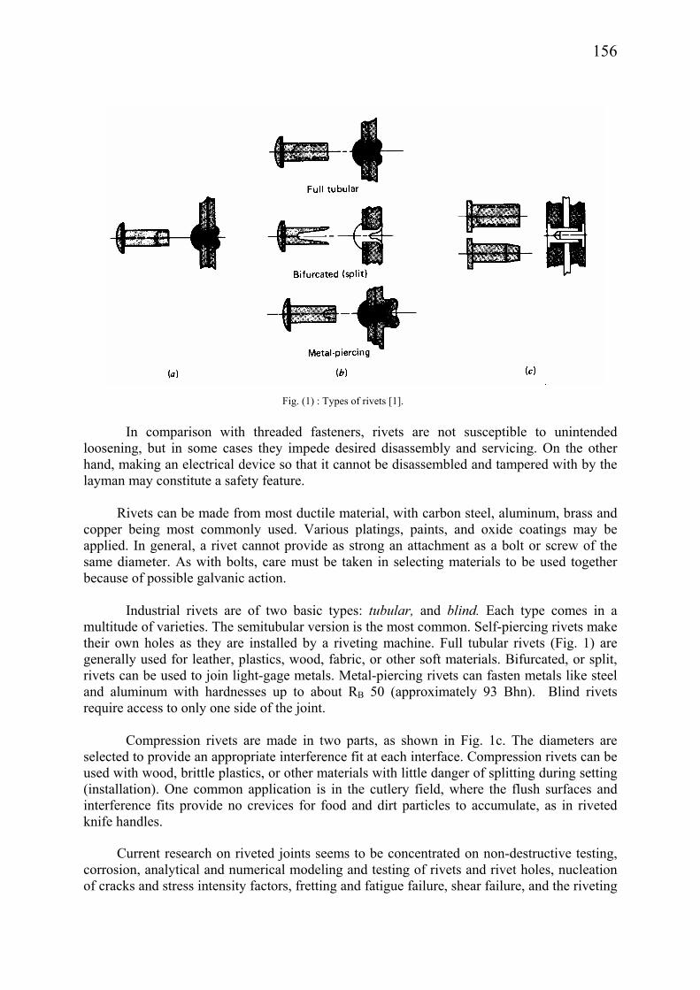
Figure 2 shows the icon of Seam Rivets. When this icon is clicked, the user accesses the main screen (Fig. 3) of the software which enables the analysis and design of riveted connections.
Lined horizontally at the top of the mainscreen are the prompts File, Objective,
Optimum pattern, Materials, Solve, Report and About. Several of these are repeated in a contact-sensitive format as separate buttons lined vertically down the left side of the screen, along with the Geometry and Quit buttons.
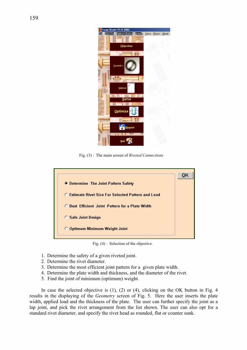
When either the Objective prompt or the Objective button is invoked, the screen of Fig.
4 pops up, whereby the user opts for one of the following objectives:
159
1. Determine the safety of a given riveted joint. 2. Determine the rivet diameter. 3. Determine the most efficient joint pattern for a given plate width. 4. Determine the plate width and thickness, and the diameter of the rivet. 5. Find the joint of minimum (optimum) weight. In case the selected objective is (1), (2) or (4), clicking on the OK button in Fig. 4
results in the displaying of the Geometry screen of Fig. 5. Here the user inserts the plate width, applied load and the thickness of the plate. The user can further specify the joint as a lap joint, and pick the rivet arrangement from the list shown. The user can also opt for a standard rivet diameter, and specify the rivet head as rounded, flat or counter sunk.
Fig. (3) : The main screen of Riveted Connections
Fig. (4) : Selection of the objective.

160
In case the joint that is under consideration is a butt joint, a new list of choices for rivet
arrangement is displayed (Fig. 5a). There may be situations where the rivet geometries shown in Figs. 5 and 5a may not be
appropriate. In such cases the user can opt for the user-defined choice, which brings up the screen of Fig. 5b. Notice in Fig. 5b that the user is given the freedom to specify the number of rows and the number of rivets in each row, in addition to the rest of the input information specified in Figs. 5 and 5a.
2.1 Determination of the Safety of Given Riveted Joint
Let there be eight 2-mm rivets with rounded heads on plates of 3 mm thickness, the plate width being 500 mm. Consider that it is desired to study the safety of this joint as a lap joint (case 1) when the applied load is 7500N. Entering this information into the menu of Fig. 5 and then clicking on OK results in the menu of Fig. 6. Note in Fig. 6 that the selected rivet is shown, and all relevant dimensions of the rivet and of the joint are listed.
Fig. (5) : The specification of the geometry of the joint.

161
Fig. (5a) : Arrangements of rivets for butt joints.
Fig. (6) : Displaying of geometrical properties of the solution.

162
Clicking next on the Stress button on the menu of Fig. 6, one obtains the menu of Fig. 6a, summarizing the stresses and where they occur.
In a similar manner opting for the Joint Properties button on Fig. 6 results in the
displaying of Fig. 6b. It is observed from Fig. 6b that the joint efficiency for the present example is only 1.4%. Furthermore, the factor of safety for the rivets is only 0.28, indicating that the rivets would fail under the given load. The factor of safety for the main plate is observed to be also less than one (0.9). the overall result for the joint is marked by the large X mark in red that is placed next to the numerical results, indicating that the joint will fail.
Clicking next on the Materials button on Fig. 6 causes the displaying of the menu of Fig. 6c, where the default materials for the rivet and the plate are displayed along with their properties. It is possible at this point to go to the Material button shown in Fig. 3, and to modify the materials for the rivets and the plates. Alternatively the user can go back and change the input data on Fig. 5 in an attempt to make the joint safe.
Opting for the latter choice, and increasing the rivet diameter from 2 mm to 4 mm, and
the plate thickness from 3 mm to 4 mm, one finds that the factors of safety are improved such that the joint becomes safe (Fig. 6d). It may be observed that the efficiency of the joint, i.e., the ratio of maximum joint strength to maximum plate strength, is also improved.
Fig. (6a) : Summary of stresses.

163
Fig. (6b) : Summary of mechanical properties of the joint.
Fig. (6c) : Summary of materials properties.

164
2.2 Determination of the Rivet Diameter Consider, as another application, that it is desired to compute the rivet diameter for a
butt joint consisting of 8 flat-head rivets and 2 mm plates of width 30 mm for a load of 7.5kN, using the default materials for both. When this information is typed into the menu of Fig. 5a, and the OK button is invoked, the user is confronted with a message, inviting him to enlarge the width of the plate since the given width is too narrow. Trying a plate width of 50 mm, it is found that the rivet diameter must be 4 mm, as indicated in Fig. 7. Figures 7a and 7b summarize the corresponding state of stresses and safety factors for the same joint. It may be noted that the joint efficiency is close to 90%, and the safety factors for the rivet and the plate are identical in this case, indicating a sound and well balanced design.
Fig. (7) : Rivet dimensions for flat head rivets in a butt joint.
Fig. (7a) : Stresses in the butt jointed flat head rivets.
Fig. (6d) : Results for the safe joint.

165
2.3 Determination of the Plate Width and Thickness, and the Diameter of the Rivet
For a third application let it be required to determine the plate thickness and width of a
plate for a butt joint with 8 rivets for counter sunk rivet holes. The load is to be 7.5 kN, using the default materials for both. When this information is typed into the menu of Fig. 5a (leaving the spaces for plate width and plate thickness blank), and the OK button is invoked, it is found that the rivet diameter must be 4 mm, the plate thickness 3.8 mm and the width of the plate 42 mm, as indicated in Fig. 8. Figure 8a summarizes the corresponding safety factors for the same joint. It may be noted that the joint efficiency is about 90%, and the safety factors for the rivet and the plate are both about 2, indicating a safe design. Since in practice a plate thickness of 4 mm would be used, instead of the 3.8 mm that was computed here, the safety factors for both the plate and the rivets would be essentially identical, indicating a sound and well balanced design.
Fig. (7b) : Joint efficiency and safety factors for the butt joint.
Fig. (8) : Output geometry for the determination of plate thickness and width.

166
If now it is desired to use aluminum for rivet and plate instead of the default material,
one clicks on the Material button on Fig. 3, makes the selection, invokes the OK button, and then clicks on OK on the menu of Fig. 5, which already contains the rest of his choices. The result is summarized in Fig. 8b, where pertinent strength properties of aluminum alloy 2024-T3 are listed, along with the results buttons lined at the bottom. When the Joint Properties button is invoked, it is observed that the plate fails, with a factor of safety of 0.7. This is because the tearing (tensile) stress on the plate is 629 MPa as compared to its strength of 440 MPa. The rivet diameter is computed to be 1.6 mm in this case where 8 rivets are used.
It is interesting to note that increasing the number of rivets for the current problem only
helps decrease the rivet diameter, but it does not prevent the yielding of the plate by tearing. Decreasing the number of rivets, on the other hand, causes the rivet diameter to be increased, such that the tearing and crushing stresses are lowered. Thus decreasing the number of rivets from 8 to 6 brings down the bearing and tearing stresses to 604 and 381 MPa, respectively. The rivet diameter becomes 2 mm, the plate thickness 1 mm, and plate width 21 mm. Safety factors for both the rivet and the plate then become greater than 1.
Fig. (8b) : Solution of the butt joint with aluminum rivet and plates.
Fig. (8a) : Joint efficiency and safety factors for the butt joint with counter sunk holes.

167
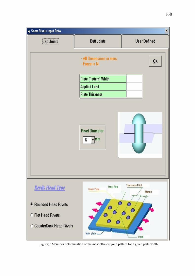
2.4 Determination of the Most Efficient Joint Pattern for a Given Plate Width Given the width and thickness of the plate and the rivet diameter, Objective #3 can be
used to determine the number of rivets needed, the allowable load for a plate factor of safety of 1.0, and the most efficient pattern for the rivets. It is understood that the materials for the plate and rivets can be selected as well. Thus selecting the third of the Objectives on Fig. 4, and then clicking on the OK button causes the menu of Fig. 9 to appear. Opting for a lap joint with a plate width of 30 mm, plate thickness of 4 mm and round headed rivets of 4 mm diameter, and then invoking the OK button produces the results presented in Figs. 9a for the default materials.
It may be observed from Fig. 9a that the total number of rivets is 12, arranged in a
mirror image type of triangular pattern. A load of 9.6 kN is allowed, and the efficiency of the joint is 80%. The maximum tearing (tensile) stress on the plate occurs at row number 2.
It would be of interest to solve the same problem for a butt joint, i.e., plate width = 30
mm, plate thickness and rivet diameter both equal to 4 mm. Entering this information in the menu of Fig. 9 and opting for a butt joint, it is found that the number of rivets becomes 9 instead of 12, and the maximum allowable load amounts to 9.9 kN. Figure 9b displays the most efficient rivet pattern. The User-Defined option is not available for the current objective.
2.5 Finding the Joint of Minimum (Optimum) Weight
When the objective is selected as #5 in the menu of Fig. 4, clicking on the OK button
causes the displaying of the menu of Fig. 10. The user is prompted to select between lap and butt type of joint, to specify the load
acting on the joint, and to specify the type of head for the rivet. Thus selecting lap rivets in the menu of Fig. 10, and specifying a load of 7.5 kN at a joint consisting of round-headed rivets, one arrives at the solution depicted in Fig. 10a. It follows that the joint fails despite the fact that 8 rivets of 4 mm diameter are utilized on a plate of 2 mm thickness and 28 mm width.
It is interesting to observe that when the same problem is solved but with the joint
specified as a butt joint, the joint does not fail. Five rivets of 5 mm diameter are utilized on a plate of 4.8 mm thickness and 35 mm width. Joint efficiency is above 80% in both cases.
It appears that lap joints of minimum weight always fail for all loads as long as the
rivet and plate materials are the same. The butt joint seems to be the winner in all cases. Lap joints where the plate material is stronger than the rivet material also produce successful joints of minimum weight.
168
Fig. (9) : Menu for determination of the most efficient joint pattern for a given plate width.

169
Fig. (9a) : The rivet pattern and the geometric part of the results.

170
Fig. (9b) : The most efficient rivet pattern for the butt joint.
Fig. (10) : The menu for the joint of minimized weight.
Fig. (10a) Results for a lap joint of minimized weight.

171
3. Concluding Remarks Seam Rivets is a user-friendly and yet a powerful tool for the analysis and design of
riveted joints that are subjected to loads that lie in the planes of plates that participate in the joint. The user starts the application by selecting an objective from among five alternatives. Thus the user may wish to
a) determine the safety of a given riveted joint, or b) determine the rivet diameter for a specific loading and plate geometry, or c) determine the plate width and thickness, and the diameter of the rivet for a given
loading. Alternatively the user may opt to d) determine the number of rivets needed, the allowable load for a plate factor of
safety of 1.0, and the most efficient pattern for the rivets, given the width and thickness of the plate and the rivet diameter, or
e) determine the full details of a joint of minimum (optimum) weight, after specifying the load acting on the joint.
In all five cases the user is prompted to select between lap and butt type of joint, and to
specify the type of head for the rivet. Fullfilling of some of the objectives requires the description of the geometry of the joint,
and all involve the specification of the materials unless the use of the default material is acceptable.
Invoking next the Solve command, which is equivalent to invoking the OK button, the
software carries out a series of tedious computations, after which it presents a comprehensive report comprising a summary of stresses, joint efficiency and factors of safety, and a detailed summary of the joint geometry and properties.
One may point out that the Seam Rivets software can also be used to analyze and design
lap and butt type of joints involving screwed fasteners. With such a broad field of application, it would be expected that students of engineering as well as practicing design engineers will find Seam Rivets to be a powerful tool that facilitates the accurate analysis and design of riveted or bolted joints of the lap or butt type.
Acknowledgement: This work was sponsored by King Abdulaziz University, Jeddah,
Saudi Arabia under contract no. 102/422.

172
References [1] Juvinall, R.C., Fundamentals of Machine Component Design, Wiley, 1983. [2] Maskow, J., Use of automated riveting systems in aircraft construction, 30. National SAMPE Symposium
and Exhibition, Anaheim, CA (USA), 19-21 Mar 1985. [3] Jarfall, L., Shear loaded fastener installations, Int. J. Vehicle Design. 1986. vol. 7, no. 3-4, pp. 337-380. [4] Onjukka, Rolf, Welding vs. riveting: which has the fatigue life for airplanes?, Welding Journal (Miami,
Fla). v 75 n 7 Jul 1996, p 29-33. [5] Gaul L; Lenz J., Nonlinear dynamics of structures assembled by bolted joints, Acta Mechanica. v 125 n
1-4 1997, p 169-181. [6] Casu A; Fregonese R; Garro A; Calderale PM., Mechanisches Verhalten von Heissnietverbindungen in
Abhangigkeit von Abkuhlung und Creep, Stahlbau. v 66, n 1, Jan 1997, p 12-19. [7] Patronelli, L; Markiewicz, E; Langrand, B; Deletombe, E; and Drazetic, P., Analysis of riveted joint
failure under mixed mode loading, European Journal of Mechanical and Environmental Engineering. v 44 n 4, Winter 1999, p 223-228.
[8] Ahlgren,Charles S; Borenstein,Susan W; Licina,George J., Inspection of aging steel penstocks, Proceedings of the International Conference on Hydropower Waterpower. v 1, 1997, ASCE, New York, NY, USA. p 77-84.
[9] Bogis, H.A., A. Abou Ezz and M. Akyurt, A user-friendly software for analysis of strain gauge rosette data, Proc. STCEX 2000, Riyadh, 18-22 Nov. 2000, V. 3, pp 187 - 197, 2000.
[10] Bogis, H.A., A. Abou Ezz, M. Akyurt and A.A.A. Alghamdi, An interactive software for curve fitting, Proc. 6th Saudi Engineering Conf., KFUPM, v 4 pp 27 – 40, 2002.
[11] Bogis, H.A., A. Abou Ezz, M. Akyurt and A.A.A. Alghamdi, An interactive software for the design of power screws, Proc. STCEX 2002, Riyadh, pp 197 - 202, 2002.
173
تصميم وتحليل وصالت البرشام المستوية باستخدام الحاسوب
عبدالملك علي الجنيدي ، مهمت أكيورتهيثم عبداهللا بوقس ، علي أبوالعز ،
كلية الهندسة ، جامعة الملك عبدالعزيز، جدة
. برنامج تعليمي لتحليل وتصميم وصالت البرشام المستوية والتي تتعرض إلجهادات القص. المستخلص
ديد قطر لتحديد معامل األمان في الوصلة، أو تح: يبدأ التطبيق بتحديد هدف من أهداف البرنامج الخمسةالبرشام الالزم لمقاومة حمل معين، أو سمك األلواح المستخدمة في الوصلة وعرضها، أو أن يقوم البرنامج
.بتحديد الوصلة األفضل والمثلى من بين ستة عشر نموذجاً يقدمها البرنامج للتصميمخدم، باإلضافة إلى في جميع الحاالت يحدد المستخدم نوعية الوصلة، وكذا نوع البرشام المست
.توصيف أبعاد الوصلة من خالل اختيار نموذج من النماذج المتوفرة، أو تقديم وصفه الخاص للوصلة باستدعاء أيقونة الحّل يقدم البرنامج بعد عمليات حسابية مرهقة تقريراً مفّصالً عن اإلجهادات
ومعامل األمان بها، باإلضافة إلى جميع أبعادها المختلفة في البرشام وألواح الوصلة، وكذا عن كفاءتها .الهندسية