Embed Size (px)
Citation preview
Preprint version 2nd IFAC Workshop RED-UAS, France (2013)
An Open-Source Hardware/SoftwareArchitecture for Quadrotor UAVs
Riccardo Spica ∗ Paolo Robuffo Giordano ∗∗ Markus Ryll ∗∗∗Heinrich H. Bülthoff ∗∗∗ Antonio Franchi ∗∗∗
∗ Inria Rennes Bretagne Atlantique and IRISA, Campus de Beaulieu,35042 Rennes Cedex, France; (e-mail: [email protected]).
∗∗ CNRS at IRISA, Campus de Beaulieu, 35042 Rennes Cedex, France(e-mail: [email protected])
∗∗∗Max Planck Institute for Biological Cybernetics, Spemannstraße 38,72076 Tübingen, Germany,
(e-mail: [email protected])
Abstract: In this paper, we illustrate an open-source ready-to-use hardware/software archi-tecture for a quadrotor UAV. The presented platform is price effective, highly customizable,and easily exploitable by other researchers involved in high-level UAV control tasks and foreducational purposes as well. The use of object-oriented programming and full support ofRobot Operating System (ROS) and Matlab Simulink allows for an efficient customization,code reuse, functionality expansion and rapid prototyping of new algorithms. We provide anextensive illustration of the various UAV components and a thorough description of the mainbasic algorithms and calibration procedures. Finally, we present some experimental case studiesaimed at showing the effectiveness of the proposed architecture.
1. INTRODUCTION
Quadrotors are Unmanned Aerial Vehicles (UAVs) actu-ated by four fixed-pitch independent propellers located atthe vertexes of a cross-shaped structure [11]. In additionto being able to take-off and land vertically, quadrotorscan reach high angular accelerations thanks to the rela-tively long lever arm between opposing motors. This makesthem more agile than most standard helicopters or similarrotorcraft UAVs. For these reasons, and also because oftheir affordability and mechanical robustness, this plat-form has witnessed a considerable growing interest in therobotics and hobbyist community over the last decade,being, in some cases, also commercialized as off-the-shelfproducts [1, asc].
Nowadays, most of the research efforts are not dealing withmore accurate dynamical modeling, or novel flight controldesign, as these issues have reached an adequate level ofmaturity and do not need further major improvements, atleast concerning standard applications. The challenge israther on how to exploit these systems as a flexible plat-form for implementing and validating complex and higher-level tasks, often involving multiple robots interacting atthe same time in partially structured or unstructuredenvironments. Some examples in this sense can be foundin, e.g., [14, 12, 2].
Nevertheless, obtaining a reliable and operative quadrotorplatform for experimental purposes still requires a con-siderable investment of time and resources for properlytuning the system, e.g., for taking care of identificationand calibration of all the various parameters (offsets, bi-ases, motor curves), gain tuning of the flight controller,implementation of accurate onboard state estimation fil-
ters, and, last but not least, software development anddebugging. These issues are obviously common to anyrobot, but, we believe, are particularly sensitive for flyingrobots as the malfunctioning of any hardware/softwarecomponent can easily result in a severe crash and loss ofthe vehicle. Because of these reasons, many ready-to-useplatforms have been proposed over the last years, each ofthem with their pros/cons and spanning a wide range ofprices.
The Hummingbird and Pelican quadrotors by AscendingTechnologies are probably the most widespread platformsin the research community (see, e.g., [14, 12]). They arecharacterized by a solid flight performance thanks to theirlightweight rigid structure, but their price is still expensivecompared to other solutions. An alternative consumer-oriented and cheaper quadrotor platform, employed insome research projects, is the AR.Drone Parrot [1] whichis able to achieve a stable near hovering flight only usingits onboard sensors. However, being the AR.Drone aninexpensive quadrotor designed for the general consumermarket, it possesses clearly some drawbacks when usedwithin a research project, e.g., 1) it does not allow for thetuning and customization that are often required in re-search projects, 2) it is not possible to integrate additionalsensors and high performance computational units (dueto the extremely low payload and fragile structure), and3) the usability of the integrated sensors for testing newalgorithms is limited by their quality and the latencies atwhich the corresponding signals can be accessed. Further-more, both these architectures are closed-source and thelow-level controller cannot be freely customized to complywith the users’ needs.
As for open-source architectures, an interesting surveyof some existing projects can be found in [7]. Many ofthe referenced solutions are extremely competitive whencompared to their price. Nevertheless, in our opinionnone of them possesses enough computational resourcesto run onboard the typical complex algorithms requiredfor a truly autonomous operation of quadrotor UAVs,such as, e.g., intensive image processing and/or high loadcommunication management. Another project, similar tothe one presented in this paper, is described in [13]. Theauthors exploit the same hardware used in this work, butthey do not customize the low-level controller providedby the manufacturer and strongly rely on a ground-basedcomputer for all computations.
With respect to all these solutions, the goal of this paper isto propose a open-source and relatively cheap architecturefor a quadrotor UAV characterized by the basic hardwareand software components that can be used within aneducational and research project to perform autonomousflight and onboard implementation of complex behaviors.For this purpose we are making the complete source codeand specs available on a freely-accessible repository fordissemination purposes and easy re-use by other researchgroups (see https://svn.kyb.mpg.de/kyb-robotics/).From a hardware point of view, the proposed platform ispurposely simple, highly customizable and easy to main-tain. Every component can be bought off-the-shelf, andthe use of standard software architectures and protocolallows for some flexibility in the hardware setup. As froma software point-of-view, the use of object-oriented pro-gramming and the support of the Robot Operating Sys-tem (ROS) and Matlab Simulink environments allow forefficient customization, code reuse, functionality expansionand rapid prototyping of new algorithms. Finally, for thesake of completeness and re-usability, we also give hands-on details on all the calibration procedures necessary foridentifying the dynamic parameters of the quadrotor, andon its basic flight control algorithms.
The paper is organized as follows: Secs. 2–3 describe thegeneral hardware and software architecture of the pro-posed quadrotor platform. Then, Secs. 4–6 provide detailson the implemented trajectory tracking controller, relevantcalibration procedures, and state estimation schemes. Fi-nally, Sec. 7 reports some experimental results for somerelevant test cases meant to illustrate the potential andperformance of the proposed platform, and Sec. 8 drawssome conclusions and discusses future directions.
2. HARDWARE DESIGN
The main goals driving our hardware design can be sum-marized as follows:
• keeping the cost of the overall components as low aspossible, when compared to equivalent solutions,• guaranteeing a wide availability of all the componentsby avoiding the use of customized hardware,• ensuring an adequate onboard computational power,for the reduced payload of a typical small-size quadro-tor platform,• ensuring that both the actuation and sensing capa-bilities of the platform are made fully interfaced withthe ROS environment.
Taking into account the aforementioned specifications, wefound a suitable solution in using the mechanical frame,actuators, microcontrollers, and inertial measurement unit(IMU) of the MK-Quadro 1 platform, by nevertheless re-placing the control layer provided by the manufacturer,introducing new components, and completely redesigningthe interface to the platform actuation and sensing re-sources.
The actuation system of the MK-Quadro consists of fourplastic propellers with a diameter of 0.254m, and a totalspan and weight of the frame of 0.5m and 0.12 kg, respec-tively. The avionics, attached to the center plate of theframe, consists of: i) a Pico-ITX LP-170C motherboardby COMMELL, equipped with a dual core Intel R©AtomTM
64 bit 1.80GHz CPU, 2GB DDR2 RAM, 16GB CompactFlash Type-II memory and a PCIE mini wireless board,ii) a low-level 8-bit Atmega1284p microcontroller, clockedat 20MHz, connected to the mini-computer trough twoRS232 serial ports and a MAX232 converter. The serialconnections operate at a baud-rate of 115 200Bd iii) fourbrushless controllers connected to the low-level controllerthrough a standard I2C bus, iv) three 3D LIS344alhaccelerometers (0.0039g0 m/s2 resolution and ±2g0 m/s2range) and three ADXRS610 gyros (0.586 deg/s resolutionand ±300 deg/s range), directly connected to the analog todigital 10 bit converters of the low-level microcontroller.In addition to this, the platform is also equipped witha pressure sensor. The whole system is powered by a2600mAh LiPo battery which guarantees an endurance ofaround 10min of flight in normal regimes. The completesystem has a weight of approximately 1.300 kg.
On top of this basic setup the system permits the easyaddition of onboard exteroceptive sensor, as done, e.g., in[3, 2] by using onboard monocular cameras. The use of anonboard RGB-D sensor is currently under development.
We finally note that this hardware solution should beregarded as a suggested configuration, i.e., as a well testedand consolidated, rather than as a mandatory one. Indeed,other hardware choices are possible: in particular, thehigh-level control software can be run on any standardx86/64 architecture without additional effort. Moreover,since the source code is freely distributed, it is possible(with, probably, some more effort in this case) to compileand run it on different architectures. Finally, concerningthe mechanical components, any equivalent configurationcan be used by suitably adjusting the control/estimationgains.
3. SOFTWARE ARCHITECTURE
The software solution developed for our platform is meantto comply with the following specifications:
• possibility of distributing the full open-source code,• use of an object-oriented high-level programminglanguage (such as C++ or Python),• possibility of providing the user with a working sys-tem in terms of flight control, making the platformready-to-use in laboratory conditions so as to, e.g.,test new state estimation and planning algorithms forexploration or multi-robot formation controllers,
1 http://www.mikrokopter.dePreprint version 2 2nd IFAC RED-UAS (2013)
����
������� �
� �����
�����
� ��� ���
���������
�� �!���"������# ���$���� �
�%� �� ��
&�'�(� �� �� ��
&�'�(� �)
����"*�+�#�������
,!����-���
&������� �
&�����.
� ������ ��
����� ��
$/)������� ��
����"*�+�#01�23����
4�
�26
�1�
����� �1������
����� �0������
���� �� ����
.�� �� )�
&%� �� ���
���������
Base station
Exterocept.Sensors
Either on-board or off-board
Position/Orientation or Bearing node ROS
Flight
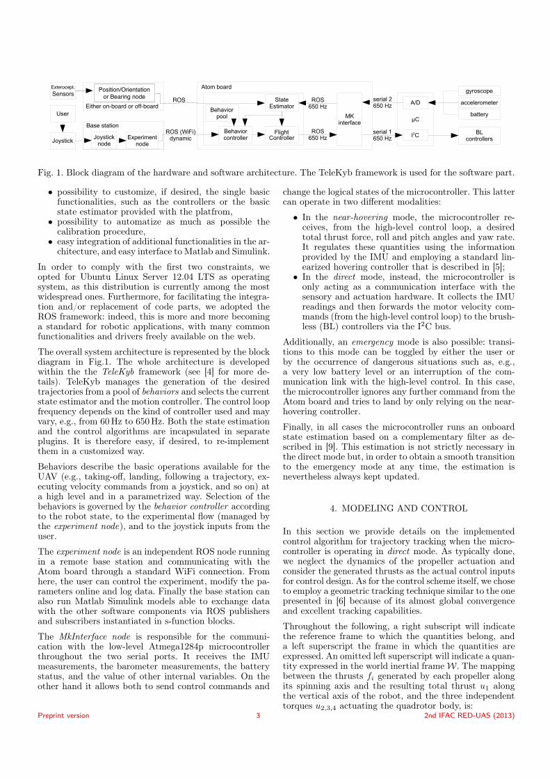
Fig. 1. Block diagram of the hardware and software architecture. The TeleKyb framework is used for the software part.
• possibility to customize, if desired, the single basicfunctionalities, such as the controllers or the basicstate estimator provided with the platfrom,• possibility to automatize as much as possible thecalibration procedure,• easy integration of additional functionalities in the ar-chitecture, and easy interface to Matlab and Simulink.
In order to comply with the first two constraints, weopted for Ubuntu Linux Server 12.04 LTS as operatingsystem, as this distribution is currently among the mostwidespread ones. Furthermore, for facilitating the integra-tion and/or replacement of code parts, we adopted theROS framework: indeed, this is more and more becominga standard for robotic applications, with many commonfunctionalities and drivers freely available on the web.
The overall system architecture is represented by the blockdiagram in Fig.1. The whole architecture is developedwithin the the TeleKyb framework (see [4] for more de-tails). TeleKyb manages the generation of the desiredtrajectories from a pool of behaviors and selects the currentstate estimator and the motion controller. The control loopfrequency depends on the kind of controller used and mayvary, e.g., from 60Hz to 650Hz. Both the state estimationand the control algorithms are incapsulated in separateplugins. It is therefore easy, if desired, to re-implementthem in a customized way.
Behaviors describe the basic operations available for theUAV (e.g., taking-off, landing, following a trajectory, ex-ecuting velocity commands from a joystick, and so on) ata high level and in a parametrized way. Selection of thebehaviors is governed by the behavior controller accordingto the robot state, to the experimental flow (managed bythe experiment node), and to the joystick inputs from theuser.
The experiment node is an independent ROS node runningin a remote base station and communicating with theAtom board through a standard WiFi connection. Fromhere, the user can control the experiment, modify the pa-rameters online and log data. Finally the base station canalso run Matlab Simulink models able to exchange datawith the other software components via ROS publishersand subscribers instantiated in s-function blocks.
The MkInterface node is responsible for the communi-cation with the low-level Atmega1284p microcontrollerthroughout the two serial ports. It receives the IMUmeasurements, the barometer measurements, the batterystatus, and the value of other internal variables. On theother hand it allows both to send control commands and
change the logical states of the microcontroller. This lattercan operate in two different modalities:
• In the near-hovering mode, the microcontroller re-ceives, from the high-level control loop, a desiredtotal thrust force, roll and pitch angles and yaw rate.It regulates these quantities using the informationprovided by the IMU and employing a standard lin-earized hovering controller that is described in [5];• In the direct mode, instead, the microcontroller is
only acting as a communication interface with thesensory and actuation hardware. It collects the IMUreadings and then forwards the motor velocity com-mands (from the high-level control loop) to the brush-less (BL) controllers via the I2C bus.
Additionally, an emergency mode is also possible: transi-tions to this mode can be toggled by either the user orby the occurrence of dangerous situations such as, e.g.,a very low battery level or an interruption of the com-munication link with the high-level control. In this case,the microcontroller ignores any further command from theAtom board and tries to land by only relying on the near-hovering controller.
Finally, in all cases the microcontroller runs an onboardstate estimation based on a complementary filter as de-scribed in [9]. This estimation is not strictly necessary inthe direct mode but, in order to obtain a smooth transitionto the emergency mode at any time, the estimation isnevertheless always kept updated.
4. MODELING AND CONTROL
In this section we provide details on the implementedcontrol algorithm for trajectory tracking when the micro-controller is operating in direct mode. As typically done,we neglect the dynamics of the propeller actuation andconsider the generated thrusts as the actual control inputsfor control design. As for the control scheme itself, we choseto employ a geometric tracking technique similar to the onepresented in [6] because of its almost global convergenceand excellent tracking capabilities.
Throughout the following, a right subscript will indicatethe reference frame to which the quantities belong, anda left superscript the frame in which the quantities areexpressed. An omitted left superscript will indicate a quan-tity expressed in the world inertial frameW. The mappingbetween the thrusts fi generated by each propeller alongits spinning axis and the resulting total thrust u1 alongthe vertical axis of the robot, and the three independenttorques u2,3,4 actuating the quadrotor body, is:
Preprint version 3 2nd IFAC RED-UAS (2013)
u =
u1u2u3u4
=
1 1 1 10 l 0 −l−l 0 l 0c −c c −c
f1f2f3f4
= Mu, (1)
where l represents the distance of the propeller rotationalaxes from the center of the robot frame and c is a constantrelated to the propeller characteristics.
The robot state consists of the position and orientationof the body frame B w.r.t. the world inertial frame W,namely rB and WRB, together with the correspondingtime-derivatives, i.e. the linear and angular velocity (rBand BωBW). Assuming that the robot barycenter is posi-tioned in the geometric center, we obtain
mrB +mgzW = u1zB, (2)J BωBW + [BωBW ]×J
BωBW = (u2, u3, u4)T , (3)
where m and J are the total mass and the (constant)inertia tensor of the robot respectively, zB is the Z-axisof the body frame and [BωBW ]× is the skew-symmetricmatrix associated to vector BωBW .
Given a desired trajectory (rB,t, ψt) for the robot positionand yaw angle with all necessary derivatives, and havingdefined the position and velocity errors as ep = rB,t − rBand ev = rB,t − rB, we can introduce a desired force as aPID action plus gravity cancellation
fd = mrB,t+Khlp ep+Khl∫
p
∫ t
0
epdt+Khlv ev+mgzW , (4)
where Khlp , Khl∫
pand Khl
v are positive diagonal matrices.
The desired force fd can be realized by choosing u1 =fTd zB and by aligning the body vertical axis with thedirection of fd. The desired robot attitude, described bythe rotation matrix WRB,d, can then be chosen so thatits third column is zB,d = fd
‖fd‖ . The remaining degrees offreedom are then set so as to minimize the yaw error. Thisis obtained by defining
yC,d = (− sinψt cosψt 0)T,
and by choosing the first and second columns of WRB,das:
xB,d =yC,d × zB,d‖yC,d × zB,d‖
, yB,d = zB,d × xB,d.
The orientation error can then be defined as
eR =1
2
(WRTBWRB,d − WRT
B,dWRB
)∨,
where ∨ indicates the vee-map that relates a skew-symmetric matrix to its corresponding 3-vector. The an-gular velocity error is instead
eω = WRTBWRB,d
B,dωBW,d − BωBWwhere B,dωBW,d can be computed as a function of the spec-ified trajectory of the robot barycenter and its derivativesup to the third order (see [16]). Finally the torque inputscan be chosen as
(u2, u3, u4)T = Khl
R eR +Khl∫R
∫ t
0
eRdt+Khlω eω + [BωBW ]×J
BωBW
+ J(WRT
BWRB,d
B,dωBW,d − [BωBW ]×WRT
BWRB,d
B,dωBW,d)
(5)where Khl
R , Khl∫R
and Khlω are positive diagonal matrices.
Note that this control law essentially consists of a PID
action, a cancellation of the gyroscopic force and a feed-forward term B,dωBW,d that can be computed as a functionof the specified trajectory of the robot barycenter and itsderivatives up to the fourth order (see again [16]).
At this point, since matrix M in (1) has full rank, itcan be inverted to obtain the single motor thrusts fi.As well-known, and shown in Sec. 5, these are related tothe spinning velocities of the propellers which are thentreated as references for the motor controllers. Neverthe-less, directly feeding these references may conflict withany internal saturations due to the limited motor power.The resulting actuation can therefore significantly differfrom the desired one. It is then necessary to properly scaledown the control inputs in order to make them feasibleby the motor controllers. We can achieve this goal bysplitting the reference control input u in a componentug = (mg, 0, 0, 0)T , necessary for compensating gravity inhovering, and a second component ures = u−ug on whicha uniform scaling is applied until all the resulting propellerthrusts lie in the admissible range [fmin, fmax]. In practiceone has to solve the following optimization problem:
min{λ}
1
2‖u− (ug + λures)‖2
s.t. fmin ≤ A−1(ug + λures) ≤ fmax, λ ≤ 1.
Note that an admissible solution always exists, providedthat ug is a feasible input. Moreover the use of a uniformscaling guarantees that the direction of the control inputis maintained.
5. CALIBRATION AND IDENTIFICATION
A necessary condition for obtaining good flight perfor-mance is a proper calibration of all the dynamic parame-ters of the system. In this section we describe how one caneasily obtain an accurate estimation of: i) the accelerom-eter bias, ii) the gyroscope bias, iii) the motor/propellercharacteristics iv) the mass and inertia matrix of the robot.For the sake of simplicity we will assume that the worldZ-axis is aligned with the direction of gravity.
5.1 Gyroscope bias calibration
The bias of the gyroscope is defined as the output of thesensor when not experiencing any rotation. This bias isinfluenced by many variable factors like, e.g. the tem-perature, and it is then affected by considerable drift.As a consequence the calibration of this sensor must berepeated often enough. We therefore decided to completelyautomate this operation: each time theMkInterface node isrestarted, a fixed number N of gyro samples are registered.The mean of the readings is then taken as a bias, providedthat their standard deviation is below a certain threshold.Otherwise an error is thrown.
5.2 Accelerometer bias calibration
As well-known, an accelerometer measures its accelerationw.r.t. the inertial frame apart from any gravity component.Any accelerometer is affected by a bias, defined as theoutput of the sensor during free-fall under gravity. Inaddition, a scaling factor and a roto-translation w.r.t. theUAV body frame can also be present after being mounted.Differently from the gyroscope case, the accelerometer bias
Preprint version 4 2nd IFAC RED-UAS (2013)
0 100 200 300 400−5
−3
−1
1
3
5
7
9
t
fi
0
200
400
600
800
reference
(a)
0 1 2 3 4 5 6 70
20406080
100120140160180200
fi
reference
data points
sqrt fit
(b)
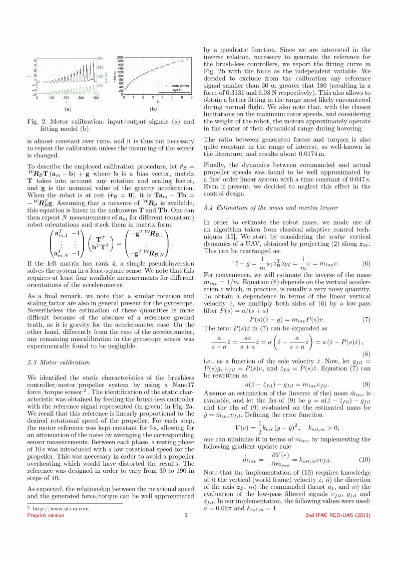
Fig. 2. Motor calibration: input/output signals (a) andfitting model (b).
is almost constant over time, and it is thus not necessaryto repeat the calibration unless the mounting of the sensoris changed.
To describe the employed calibration procedure, let rB =WRBT (am − b) + g where b is a bias vector, matrixT takes into account any rotation and scaling factor,and g is the nominal value of the gravity acceleration.When the robot is at rest (rB = 0), it is Tam − Tb =−WRT
Bg. Assuming that a measure of WRB is available,this equation is linear in the unknowns T and Tb. One canthen repeat N measurements of am for different (constant)robot orientations and stack them in matrix form:aTm,1 −1
......
aTm,N −1
( TT
bTTT
)=
−gT WRB,1...
−gT WRB,N
.
If the left matrix has rank 4, a simple pseudoinversionsolves the system in a least-square sense. We note that thisrequires at least four available measurements for differentorientations of the accelerometer.
As a final remark, we note that a similar rotation andscaling factor are also in general present for the gyroscope.Nevertheless the estimation of these quantities is moredifficult because of the absence of a reference groundtruth, as it is gravity for the accelerometer case. On theother hand, differently from the case of the accelerometer,any remaining miscalibration in the gyroscope sensor wasexperimentally found to be negligible.
5.3 Motor calibration
We identified the static characteristics of the brushlesscontroller/motor/propeller system by using a Nano17force/torque sensor 2 . The identification of the static char-acteristic was obtained by feeding the brush-less controllerwith the reference signal represented (in green) in Fig. 2a.We recall that this reference is linearly proportional to thedesired rotational speed of the propeller. For each step,the motor reference was kept constant for 5 s, allowing foran attenuation of the noise by averaging the correspondingsensor measurements. Between each phase, a resting phaseof 10 s was introduced with a low rotational speed for thepropeller. This was necessary in order to avoid a propelleroverheating which would have distorted the results. Thereference was designed in order to vary from 30 to 190 insteps of 10.
As expected, the relationship between the rotational speedand the generated force/torque can be well approximated2 http://www.ati-ia.com
by a quadratic function. Since we are interested in theinverse relation, necessary to generate the reference forthe brush-less controllers, we report the fitting curve inFig. 2b with the force as the independent variable. Wedecided to exclude from the calibration any referencesignal smaller than 30 or greater that 180 (resulting in aforce of 0.3131 and 6.03 N respectively). This also allows toobtain a better fitting in the range most likely encounteredduring normal flight. We also note that, with the chosenlimitations on the maximum rotor speeds, and consideringthe weight of the robot, the motors approximately operatein the center of their dynamical range during hovering.
The ratio between generated forces and torques is alsoquite constant in the range of interest, as well-known inthe literature, and results about 0.0174m.
Finally, the dynamics between commanded and actualpropeller speeds was found to be well approximated bya first order linear system with a time constant of 0.047 s.Even if present, we decided to neglect this effect in thecontrol design.
5.4 Estimation of the mass and inertia tensor
In order to estimate the robot mass, we made use ofan algorithm taken from classical adaptive control tech-niques [15]. We start by considering the scalar verticaldynamics of a UAV, obtained by projecting (2) along zW .This can be rearranged as:
z − g =1
mu1z
TBzW =
1
mυ = minvυ. (6)
For convenience, we will estimate the inverse of the massminv = 1/m. Equation (6) depends on the vertical acceler-ation z which, in practice, is usually a very noisy quantity.To obtain a dependence in terms of the linear verticalvelocity z, we multiply both sides of (6) by a low-passfilter P (s) = a/(s+ a)
P (s)(z − g) = minvP (s)υ. (7)The term P (s)z in (7) can be expanded as
a
s+ az =
as
s+ az = a
(z − a
s+ az
)= a (z − P (s)z) ,
(8)i.e., as a function of the sole velocity z. Now, let gfil =P (s)g, υfil = P (s)υ, and zfil = P (s)z. Equation (7) canbe rewritten as
a(z − zfil)− gfil = minvυfil. (9)Assume an estimation of the (inverse of the) mass minv isavailable, and let the lhs of (9) be y = a(z − zfil) − gfiland the rhs of (9) evaluated on the estimated mass bey = minvυfil. Defining the error function
V (e) =1
2kest (y − y)2 , kest,m > 0,
one can minimize it in terms of minv by implementing thefollowing gradient update rule
˙minv = −∂V (e)
∂minv= kest,meυfil. (10)
Note that the implementation of (10) requires knowledgeof i) the vertical (world frame) velocity z, ii) the directionof the axis zB, iii) the commanded thrust u1, and iv) theevaluation of the low-pass filtered signals υfil, gfil andzfil. In our implementation, the following values were used:a = 0.06π and kest,m = 1.
Preprint version 5 2nd IFAC RED-UAS (2013)
Finally, we note that the same algorithm can be usedfor obtaining an estimation of the robot inertia tensor.Indeed, because of the cylindrical symmetry of the robot,the inertia matrix results practically diagonal and withthe same X and Y components. Under this assumptionthe gyroscopic term in (3) becomes negligible for a smallZ component of BωBW . The rotational dynamics can thenbe split among three independent scalar systems similarto (6), with the additional simplification of the absence ofany gravity term.
6. STATE ESTIMATION
The control algorithm described in Sec. 4 requires knowl-edge, at high rate, of the full state of the robot, i.e., of theposition rB, the velocity rB, the orientation WRB and theangular velocity BωBW . In this section we describe howto obtain an estimation of these quantities using measure-ments of linear acceleration and angular velocity availablefrom the onboard IMU, and a low rate measurements of theposition and orientation provided by any possible source(e.g., an external or onboard sensor).
6.1 Complementary filter in SE(3)
If some (possibly noisy) measurement of the robot ori-entation is available, the translational part of the robotdynamics χT = (rB, rB)
T has the linear expression
χT =d
dt
(rBrB
)=
(03×3 I3×303×3 03×3
)χT
+
(03×1
WRBT (am − b) + g
)= AχT + υ.
By assuming a low-rate and possibly noisy measurement ofthe position rB is available, it is straightforward to checkthat the system is observable and a simple linear stateobserver can be easily designed as:
˙χT = AχT + υ +Kest,p (rB − rB) . (11)We note that one can also estimate the accelerometerbias b. Indeed by considering the extended state χ′T =
(rB, rB,b)T , one has
χ′T =d
dt
(rBrBb
)=
(03×3 I3×3 03×303×3 03×3 −WRBT03×3 03×3 03×3
)χ′T+
+
(03×1
WRBTam + g03×1
)= A′χT + υ′.
.
It is easy to prove observability w.r.t. the position rBmeasurement in this case, too, thus allowing to implementan observer similar to (11).
As for the orientation, we implemented the complementaryfilter in SO(3) described in [10], in particular the so-called passive complementary filter without gyro bias es-timation (already compensated for during the calibrationof Sec. 5), and using the quaternion-based formulation.Let WqB = (WqB,s,
WqB,v) be the unit-norm quaternioncorresponding to WRB with scalar and vector part WqB,sand WqB,v, respectively. As well-known, the kinematics ofthe quaternion is given by:
WqB =1
2WqB ⊗
(0, BωBW
)
where ⊗ indicates the quaternion product defined as:p⊗ q =
(psqs − pTv qv, psqv + qspv + pv × qv
).
Assuming that a low-rate and possibly noisy measureof the orientation WqB is available, we can define anorientation error as
δq = Wq∗B ⊗ WqB = (δqs, δq)
where the conjugate is defined as q∗ = (qs,−qv). Theestimation of the orientation can then be updated asfollows:
W ˙qB =1
2WqB ⊗
(0, BωBW + 2Kest,qδqsδqv
). (12)
In order to enforce the unit-norm constraint during thenumerical integration, we slightly modified (12) by addinga penalty term proportional to the squared norm of theestimated quaternion:W ˙qB =
1
2WqB ⊗
(2λ(1−
∥∥WqB∥∥2),ωm + 2Kest,qδqsδqv
)where ωm is the angular velocity measured by the gyro-scope corrected for the calibrated bias. Finally, we em-ployed the following values: Kest,p = 126.3I3, Kest,v =3987.3I3, and Kest,q = 62.8I3.
The last part of the state to be estimated is the angularvelocity BωBW . In principle this quantity is already pro-vided by the onboard gyroscope. In practice the output ofthis sensor during a typical flight is too noisy to be directlyfed to the controller. Therefore, we low-pass filtered BωBWas ˙ω = 2πfω(ωm − ω) with fω = 150 Hz.
6.2 Extension to bearing-only measurements
The state estimation algorithm described above requiresa low-rate and possibly noisy direct measurement of theposition and orientation of the robot. Since these mea-surements are not always available in a laboratory, wehere detail a ready-to-use algorithm able to recover thesequantities from a set of (at least 4) bearing measurementsfrom some beacons with known identity and position inthe world frame. This is, indeed, representative of manysituations involving an onboard camera extracting featuresfrom the scene.
The reconstruction of the robot pose can be obtained byexploiting standard techniques from geometrical computervision. The basic algorithm, described in [8], is here brieflysummarized: first, consider a set of N points p belongingto the same 2D plane and assume that two bearingmeasurements are available for each point, namely xi,1 andxi,2 for i = 1 . . . N . These two bearings are associated totwo frames (in our case the world and the body framerespectively). The plane is described by the followingequation in the first reference frame:
P ={X1 : nT1X1 = d
}⇔ 1
dnT1X1 = 1 (13)
where X1 contains the coordinates of the point p in thefirst frame, n1 is the unit normal vector to the plane andd is the distance of the plane from the origin of the firstframe. Note that, since we have assumed a known beaconposition in the world frame, all these quantities are alsoavailable.
Letting (WRB, rB) represent the rotation/translationamong the two frames, and exploiting (13), one has
Preprint version 6 2nd IFAC RED-UAS (2013)
X2 =
(WRB +
1
drBn
T1
)X1 = HX1
where H is the so-called homography matrix. The homog-raphy H can be directly retrieved from a set of at leastfour bearing pairs (in the reference and current frame)by means of the standard four-point algorithm for planarscene as described in [8]. Once recovered, H can then bedecomposed back into the rotation WRB and the transla-tion rB: let (n′1,n
′′1) be a pair of unit-norm vectors such
that (n1,n′1,n′′1) forms a right hand frame. Note that
(n′1,n′′1) are a basis of the null space of n1
T . By projectingthe homography matrix along these vectors, we obtain
H (n′1 n′′1) = (m′1 m′′1) =WRB (n
′1 n′′1) .
By then taking m1 = m′1 ×m′′1 , WRB is finally recoveredas
WRB = (m1 m′1 m′′1) (n1 n′1 n′′1)T.
Once WRB has been found, t is simply given by t =d(H− WRB
)where d is assumed known, as explained
above. This then allows to recover a measurement of therobot pose (WRB, rB) that can be used in the comple-mentary filter described in Sec. 6.1 .
7. EXPERIMENTAL CASES STUDIES
In this section we present some experimental results ob-tained with the proposed platform. In the first two experi-ments we used an external tracking system 3 to providepose measurements directly to the estimator describedin 6.1. For the last experiment, instead, we used theexternal tracking system only for simulating low-rate andnoisy bearing measurements similar to those that wouldbe provided by typical onboard localization systems (e.g.,vision-based) available in the literature.
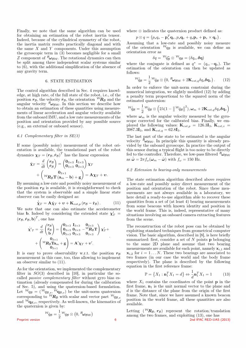
The aim of the first experiment was to prove the per-formance of the mass estimation algorithm in hoveringconditions and during arbitrary motion. To this end, weintentionally initialized the system from an initial guessfor the estimated mass of 1 kg, i.e. 0.308 kg less than thenominal value. The result of the experiment is shown inFig. 3. At the beginning of the experiment, the controllercommanded a vertical thrust not sufficient for the robotto take off due to the low value of the estimated mass.After the take-off, the robot was then commanded tohover at a constant position until the estimated mass hadreached its final value (about 1.394 kg). The convergenceof the estimation can be detected by setting a thresholdon its variance. We then manually controlled the cartesianvelocity of the robot in a random way for verifying thatthe mass estimation was remaining constant despite theerratic motion. Figure 3c shows the actual robot velocityas estimated via the techniques illustrated in Sec. 6.
In the second experiment we show the tracking perfor-mance of our control algorithm while following an 8-shapedhorizontal trajectory in X and Y (see Fig. 4). The 8 shapehas a bounding box of size 1m×1m and is completed in8 s. Both the Z position and the yaw reference were variedduring motion by following sinusoidal-like trajectories withan amplitude of 0.2m and frequency of 1 rad, respectively.The timing law was chosen to ensure the needed smooth-ness for the reference sent to the controller, i.e., continuous3 http://www.vicon.com/
0 10 20 30 40 50 60
1
1.2
1.4
m[kg]
(a)
0 10 20 30 40 50 60
−2
0
2
rB[m
]
(b)
0 10 20 30 40 50 60
−2
−1
0
1
time[s]
rB[m
]
(c)
Fig. 3. Mass estimation during a normal flight. Fig. (a):estimated mass. Fig. (b): UAV position. Fig. (c) andUAV velocity.
0 2 4 6 8 10 12
−2
−1
0
1
time[s]
rB[m
]
(a)
0 2 4 6 8 10 12
−1
0
1
time[s]
Y
(b)
0 2 4 6 8 10 12
−0.1
0
0.1
time[s]
erB[m
]
(c)
0 2 4 6 8 10 12
−0.5
0
0.5
time[s]eY[rad]
(d)
Fig. 4. Tracking of an eight shaped trajectory. Fig. (a):UAV cartesian position. Fig. (b): UAV yaw angle.Fig. (c): position error. Fig. (d): yaw angle error.
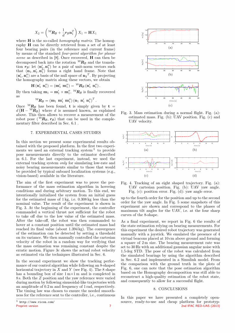
up to the fourth order for the position and up to the secondorder for the yaw angle. In Fig. 5 some snapshots of thisexperiment are shown and correspond to the phases ofmaximum tilt angles for the UAV, i.e. at the four sharpcurves of the 8-shape.
As a final experiment, we report in Fig. 6 the results ofthe state estimation relying on bearing measurements. Forthis experiment the desired robot trajectory was generatedmanually with a joystick. We emulated the presence of 4virtual beacons placed at 10 cm above ground and forminga square of 2m size. The bearing measurement rate wasset to 30Hz with an additional gaussian angular noise with1.5 deg STD. The pose of the robot was calculated fromthe simulated bearings by using the algorithm describedin Sec. 6.2 and implemented in a Simulink model. Fromthe comparison with the ground truth in the plots ofFig. 6, one can note that the pose estimation algorithmbased on the Homography decomposition was still able toreconstruct a high-quality estimation of the robot state,and consequently to allow for a successful flight.
8. CONCLUSIONS
In this paper we have presented a completely open-source, ready-to-use and cheap platform for prototyp-
Preprint version 7 2nd IFAC RED-UAS (2013)
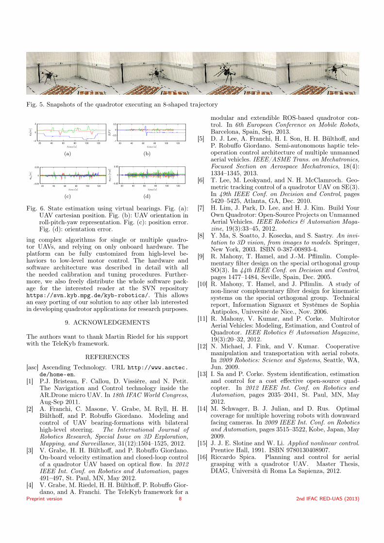
Fig. 5. Snapshots of the quadrotor executing an 8-shaped trajectory
20 40 60 80 100 120
−2
0
2
time[s]
rB[m
]
(a)
20 40 60 80 100 120
−1
−0.5
0
0.5
time[s]
RPY
(b)
20 40 60 80 100 120
−0.05
0
0.05
time[s]
erB[m
]
(c)
20 40 60 80 100 120
−0.05
0
0.05
time[s]
eRPY[rad]
(d)
Fig. 6. State estimation using virtual bearings. Fig. (a):UAV cartesian position. Fig. (b): UAV orientation inroll-pitch-yaw representation. Fig. (c): position error.Fig. (d): orientation error.
ing complex algorithms for single or multiple quadro-tor UAVs, and relying on only onboard hardware. Theplatform can be fully customized from high-level be-haviors to low-level motor control. The hardware andsoftware architecture was described in detail with allthe needed calibration and tuning procedures. Further-more, we also freely distribute the whole software pack-age for the interested reader at the SVN repositoryhttps://svn.kyb.mpg.de/kyb-robotics/. This allowsan easy porting of our solution to any other lab interestedin developing quadrotor applications for research purposes.
9. ACKNOWLEDGEMENTS
The authors want to thank Martin Riedel for his supportwith the TeleKyb framework.
REFERENCES
[asc] Ascending Technology. URL http://www.asctec.de/home-en.
[1] P.J. Bristeau, F. Callou, D. Vissière, and N. Petit.The Navigation and Control technology inside theAR.Drone micro UAV. In 18th IFAC World Congress,Aug-Sep 2011.
[2] A. Franchi, C. Masone, V. Grabe, M. Ryll, H. H.Bülthoff, and P. Robuffo Giordano. Modeling andcontrol of UAV bearing-formations with bilateralhigh-level steering. The International Journal ofRobotics Research, Special Issue on 3D Exploration,Mapping, and Surveillance, 31(12):1504–1525, 2012.
[3] V. Grabe, H. H. Bülthoff, and P. Robuffo Giordano.On-board velocity estimation and closed-loop controlof a quadrotor UAV based on optical flow. In 2012IEEE Int. Conf. on Robotics and Automation, pages491–497, St. Paul, MN, May 2012.
[4] V. Grabe, M. Riedel, H. H. Bülthoff, P. Robuffo Gior-dano, and A. Franchi. The TeleKyb framework for a
modular and extendible ROS-based quadrotor con-trol. In 6th European Conference on Mobile Robots,Barcelona, Spain, Sep. 2013.
[5] D. J. Lee, A. Franchi, H. I. Son, H. H. Bülthoff, andP. Robuffo Giordano. Semi-autonomous haptic tele-operation control architecture of multiple unmannedaerial vehicles. IEEE/ASME Trans. on Mechatronics,Focused Section on Aerospace Mechatronics, 18(4):1334–1345, 2013.
[6] T. Lee, M. Leokyand, and N. H. McClamroch. Geo-metric tracking control of a quadrotor UAV on SE(3).In 49th IEEE Conf. on Decision and Control, pages5420–5425, Atlanta, GA, Dec. 2010.
[7] H. Lim, J. Park, D. Lee, and H. J. Kim. Build YourOwn Quadrotor: Open-Source Projects on UnmannedAerial Vehicles. IEEE Robotics & Automation Maga-zine, 19(3):33–45, 2012.
[8] Y. Ma, S. Soatto, J. Kosecka, and S. Sastry. An invi-tation to 3D vision, from images to models. Springer,New York, 2003. ISBN 0-387-00893-4.
[9] R. Mahony, T. Hamel, and J.-M. Pflimlin. Comple-mentary filter design on the special orthogonal groupSO(3). In 44th IEEE Conf. on Decision and Control,pages 1477–1484, Seville, Spain, Dec. 2005.
[10] R. Mahony, T. Hamel, and J. Pflimlin. A study ofnon-linear complementary filter design for kinematicsystems on the special orthogonal group. Technicalreport, Information Signaux et Systèmes de SophiaAntipoles, Université de Nice., Nov. 2006.
[11] R. Mahony, V. Kumar, and P. Corke. MultirotorAerial Vehicles: Modeling, Estimation, and Control ofQuadrotor. IEEE Robotics & Automation Magazine,19(3):20–32, 2012.
[12] N. Michael, J. Fink, and V. Kumar. Cooperativemanipulation and transportation with aerial robots.In 2009 Robotics: Science and Systems, Seattle, WA,Jun. 2009.
[13] I. Sa and P. Corke. System identification, estimationand control for a cost effective open-source quad-copter. In 2012 IEEE Int. Conf. on Robotics andAutomation, pages 2035–2041, St. Paul, MN, May2012.
[14] M. Schwager, B. J. Julian, and D. Rus. Optimalcoverage for multiple hovering robots with downwardfacing cameras. In 2009 IEEE Int. Conf. on Roboticsand Automation, pages 3515–3522, Kobe, Japan, May2009.
[15] J. J. E. Slotine and W. Li. Applied nonlinear control.Prentice Hall, 1991. ISBN 9780130408907.
[16] Riccardo Spica. Planning and control for aerialgrasping with a quadrotor UAV. Master Thesis,DIAG, Università di Roma La Sapienza, 2012.
Preprint version 8 2nd IFAC RED-UAS (2013)