Embed Size (px)
Citation preview
Analysis and Design of Integrated Magnetorquer
Coils for Attitude Control of Nanosatellites
Hassan Ali*, M. Rizwan Mughal*†, Jaan Praks †, Leonardo M. Reyneri+, Qamar ul Islam*
* †Department of Electrical Engineering, Institute of Space Technology, Islamabad, Pakistan,
†Department of Electronic and Nano Engineering, Aalto University, Espoo, Finland
+Department of Electronics and Telecommunications, Politecnico di Torino, Torino, Italy
Abstract—The nanosatellites typically use either magnetic rods or
coil to generate magnetic moment which consequently interacts
with the earth magnetic field to generate torque. In this research,
we present a novel design which integrates printed embedded
coils, compact coils and magnetic rods in a single package which
is also complaint with 1U CubeSat. These options provide
maximum flexibility, redundancy and scalability in the design.
The printed coils consume no extra space because the copper
traces are printed in the internal layers of the printed circuit
board (PCB). Moreover, they can be made reconfigurable by
printing them into certain layers of the PCB, allowing the user to
select any combination of series and parallel coils for optimized
design. The compact coil is wound around the available space in
a 1U complaint CubeSat panel and it can accommodate much
more number of turns compared to printed coil; consequently
generating more torque. The magnetic rod is made complaint
with the existing available options and can easily be integrated in
the panel. This design gives a lot of flexibility because one can
choose to optimize power, optimized torque or rotation time by
choosing among the available magnetorquer options. The
proposed design approach occupies very low space, consume low
power and is cost effective.
The analysis in terms of generated torque with certain applied
voltages, trace widths. The analysis results in terms of selection of
optimized parameters including torque to power ratio will be
presented.
Keywords—ADCS; Magnetorquer; Reconfigurable; Printed;
Compact; Optimum; magnetorquer Rod; Nanosatellite;
I. INTRODUCTION
With the passage of time, the size of the satellites is reducing and their applications are increasing. Due to their low price, mass and size, it has become more attractive for universities, small research organizations and space agencies to build, test and launch their own satellites. With the reduction of size of the CubeSats and nanosatellites, the designing and placement of all the subsystem in a reduced space has also
become a challenge. In order to stabilize the tumbling satellite, the attitude control system is very necessary. There are two types of attitude control systems i.e. passive and active [1-6]. The permanent magnetics and the gravity gradients are passive type. They being cost effective, consume no power but no pointing accuracy is achieved using these types of actuators. The majority of the missions these days require better pointing accuracies. The active control systems are typically used for in missions where better pointing accuracy is desired. The magnetorquer is a good option to control the attitude of nanosatellite. They use the local (earth) magnetic field to generate the torque, which is used to rotate the satellite.
In this work, we present a combined design of attitude control system by combining different types of magnetorquers to overcome the main constraints like available power, cost, mass and space availability. The printed or embedded coil, compact coil and cylindrical rod are combined in a CubeSat complaint panel to achieve three axis control. The detailed analysis has also been performed for all the types and the proposed design is also compared with the commercial designs. The thermal analysis has also been presented for the proposed design.
The ACS manages the satellite orientation, in order to
point its antennas toward ground station or solar panels
towards the sun. For this purpose normally permanent magnets,
reaction wheels and magnetic rods are used. Permanent
magnets are cheap, simple, light and consuming no power. But
they have inadequate pointing accuracy and give very little
choices on the pointing direction. Reaction wheels and
magnetic rods have better pointing accuracy and can orientate
satellite in any direction but their price, weight and size make
them incompatible with CubeSats standard Nanosatellites like
AraMiS-C1.
The best solution to this problem is the design of
reconfigurable magnetorquers which are able to produce
required magnetic moment and consequent torque for any
desired spacecraft configuration.
The design having printed magnetorquers, compact
magnetorquers and magnetic rods has been accomplished for
iCube and AraMiS satellites [8-9]. The design approach is
based on smart panels which can be integrated together to
form any CubeSat configuration [8-9]. A panel showing
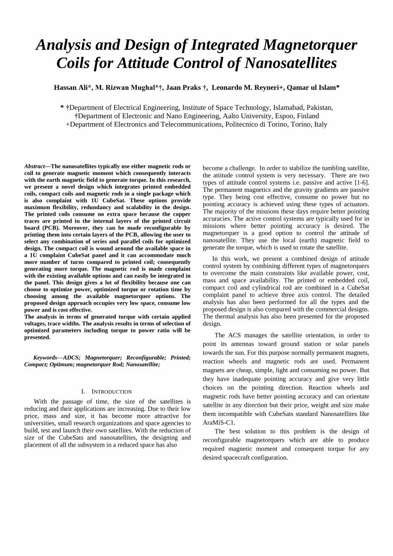
printed magnetorquer in the internal layers is shown in Fig.1.
Fig.1 Design of printed coil on a CubeSat panel
The printed Magnetorquer is a better choice for attitude
control and stabilization of Nanosatellites when the mission
requires less torque and less power consumption. The compact
magnetorquer is suitable for better pointing where consuming
more power to generate more torque. The cylindrical solution
provides best pointing but it needs more area, power to
generated torque.
The goal of this work is to provide CubeSats with
reconfigurable option of using all the possible magnetorquers
keeping power, torque, and torque to power optimized [7].
Fig.2 Flow diagram of the system
A completed flow diagram of the system is shown in Fig. 2. The attitude of the spacecraft is determined with the help of certain attitude sensors and this attitude information is sent to on board data handling system (OBDH) with the current and target attitude. The OBDH sends torque commands to actuate either compact, printed or magnetic rod after calculations of desired torque for desired attitude attainment. The new attitude is fed back to the onboard computer and the loop repeats.
This work suggests an optimized combined design where these attitude control solution are used by optimizing certain parameters like trace widths, applied voltages, to generate torques while keeping torque to power ratio optimized. The theoretical design has been verified by experimental setup.
II. MGENETORQUER DESIGN
A. Printed Magnetorquer
The printed magnetorquer design is selected by performing the theoretical calculations on generated torque, torque to power ratios for CubeSat complaint panels by changing the applied voltage. The designed printed magnetorquer is fully compliant with the CubeSat dimension and requires no extra space since the traces are embedded in the internal layers of the board. The board has been designed using optimal parameters including the selection of outer and inner copper dimensions, trace widths, distance between two adjacent traces and power consumption analysis vs the generated torque. The copper traces of magnetorquer coil are printed into the inner layer of printed circuit board (PCB). The selected dimensions of the printed magnetorquer are shown in Fig.3.
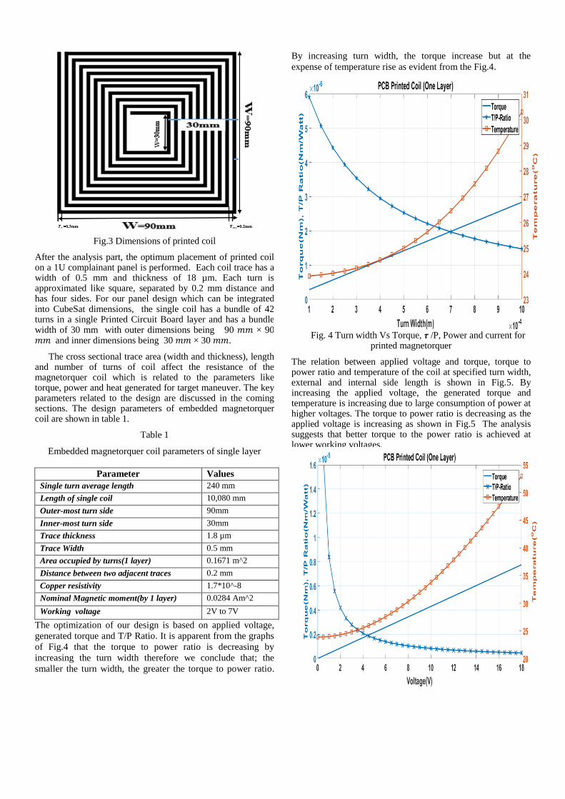
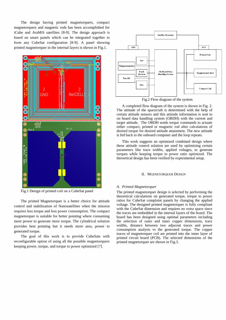
Fig.3 Dimensions of printed coil
After the analysis part, the optimum placement of printed coil on a 1U complainant panel is performed. Each coil trace has a width of 0.5 mm and thickness of 18 µm. Each turn is approximated like square, separated by 0.2 mm distance and has four sides. For our panel design which can be integrated into CubeSat dimensions, the single coil has a bundle of 42 turns in a single Printed Circuit Board layer and has a bundle width of 30 mm with outer dimensions being 90 𝑚𝑚 × 90 𝑚𝑚 and inner dimensions being 30 𝑚𝑚 × 30 𝑚𝑚.
The cross sectional trace area (width and thickness), length and number of turns of coil affect the resistance of the magnetorquer coil which is related to the parameters like torque, power and heat generated for target maneuver. The key parameters related to the design are discussed in the coming sections. The design parameters of embedded magnetorquer coil are shown in table 1.
Table 1
Embedded magnetorquer coil parameters of single layer
Parameter Values
Single turn average length 240 mm
Length of single coil 10,080 mm
Outer-most turn side 90mm
Inner-most turn side 30mm
Trace thickness 1.8 µm
Trace Width 0.5 mm
Area occupied by turns(1 layer) 0.1671 m^2
Distance between two adjacent traces 0.2 mm
Copper resistivity 1.7*10^-8
Nominal Magnetic moment(by 1 layer) 0.0284 Am^2
Working voltage 2V to 7V
The optimization of our design is based on applied voltage,
generated torque and T/P Ratio. It is apparent from the graphs
of Fig.4 that the torque to power ratio is decreasing by
increasing the turn width therefore we conclude that; the
smaller the turn width, the greater the torque to power ratio.
By increasing turn width, the torque increase but at the
expense of temperature rise as evident from the Fig.4.
Fig. 4 Turn width Vs Torque, τ /P, Power and current for printed magnetorquer
The relation between applied voltage and torque, torque to power ratio and temperature of the coil at specified turn width, external and internal side length is shown in Fig.5. By increasing the applied voltage, the generated torque and temperature is increasing due to large consumption of power at higher voltages. The torque to power ratio is decreasing as the applied voltage is increasing as shown in Fig.5 The analysis suggests that better torque to the power ratio is achieved at lower working voltages.
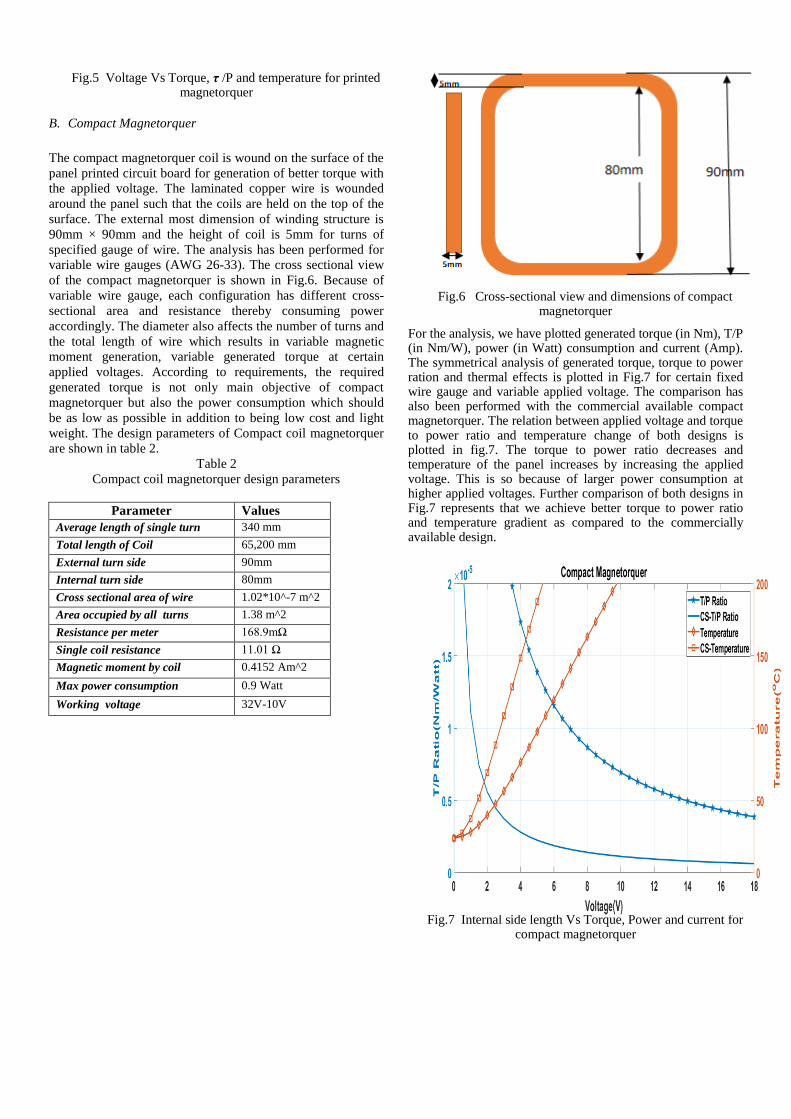
Fig.5 Voltage Vs Torque, τ /P and temperature for printed magnetorquer
B. Compact Magnetorquer
The compact magnetorquer coil is wound on the surface of the
panel printed circuit board for generation of better torque with
the applied voltage. The laminated copper wire is wounded
around the panel such that the coils are held on the top of the
surface. The external most dimension of winding structure is
90mm × 90mm and the height of coil is 5mm for turns of
specified gauge of wire. The analysis has been performed for
variable wire gauges (AWG 26-33). The cross sectional view
of the compact magnetorquer is shown in Fig.6. Because of
variable wire gauge, each configuration has different cross-
sectional area and resistance thereby consuming power
accordingly. The diameter also affects the number of turns and
the total length of wire which results in variable magnetic
moment generation, variable generated torque at certain
applied voltages. According to requirements, the required
generated torque is not only main objective of compact
magnetorquer but also the power consumption which should
be as low as possible in addition to being low cost and light
weight. The design parameters of Compact coil magnetorquer
are shown in table 2.
Table 2
Compact coil magnetorquer design parameters
Parameter Values
Average length of single turn 340 mm
Total length of Coil 65,200 mm
External turn side 90mm
Internal turn side 80mm
Cross sectional area of wire 1.02*10^-7 m^2
Area occupied by all turns 1.38 m^2
Resistance per meter 168.9mΩ
Single coil resistance 11.01 Ω
Magnetic moment by coil 0.4152 Am^2
Max power consumption 0.9 Watt
Working voltage 32V-10V
Fig.6 Cross-sectional view and dimensions of compact magnetorquer
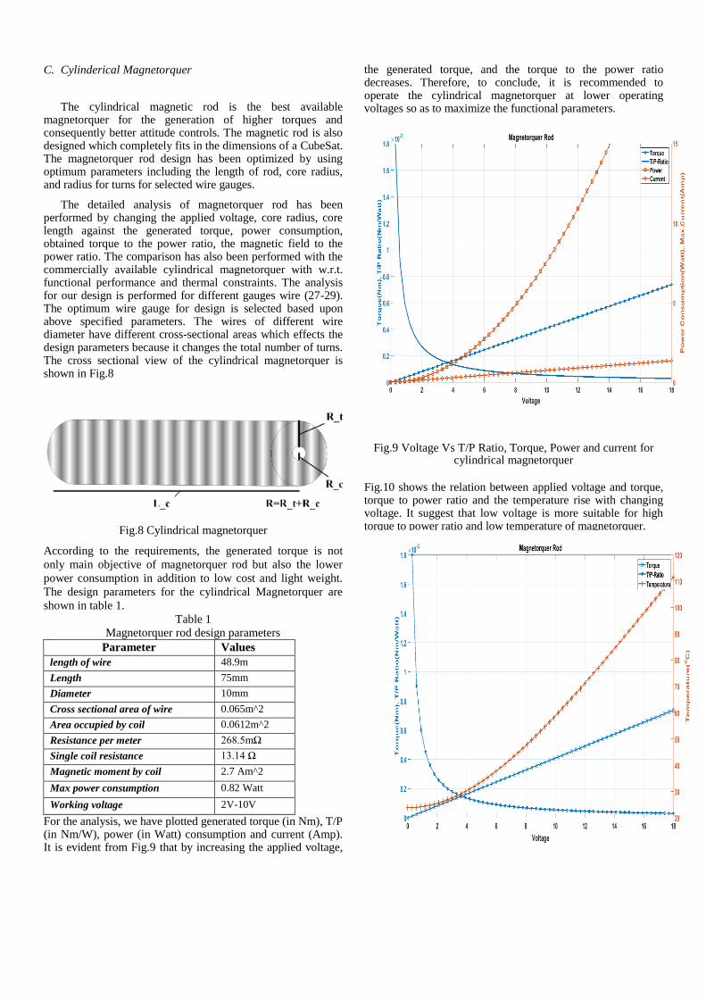
For the analysis, we have plotted generated torque (in Nm), T/P (in Nm/W), power (in Watt) consumption and current (Amp). The symmetrical analysis of generated torque, torque to power ration and thermal effects is plotted in Fig.7 for certain fixed wire gauge and variable applied voltage. The comparison has also been performed with the commercial available compact magnetorquer. The relation between applied voltage and torque to power ratio and temperature change of both designs is plotted in fig.7. The torque to power ratio decreases and temperature of the panel increases by increasing the applied voltage. This is so because of larger power consumption at higher applied voltages. Further comparison of both designs in Fig.7 represents that we achieve better torque to power ratio and temperature gradient as compared to the commercially available design.
Fig.7 Internal side length Vs Torque, Power and current for compact magnetorquer
C. Cylinderical Magnetorquer
The cylindrical magnetic rod is the best available magnetorquer for the generation of higher torques and consequently better attitude controls. The magnetic rod is also designed which completely fits in the dimensions of a CubeSat. The magnetorquer rod design has been optimized by using optimum parameters including the length of rod, core radius, and radius for turns for selected wire gauges.
The detailed analysis of magnetorquer rod has been performed by changing the applied voltage, core radius, core length against the generated torque, power consumption, obtained torque to the power ratio, the magnetic field to the power ratio. The comparison has also been performed with the commercially available cylindrical magnetorquer with w.r.t. functional performance and thermal constraints. The analysis for our design is performed for different gauges wire (27-29). The optimum wire gauge for design is selected based upon above specified parameters. The wires of different wire diameter have different cross-sectional areas which effects the design parameters because it changes the total number of turns. The cross sectional view of the cylindrical magnetorquer is shown in Fig.8
Fig.8 Cylindrical magnetorquer
According to the requirements, the generated torque is not
only main objective of magnetorquer rod but also the lower
power consumption in addition to low cost and light weight.
The design parameters for the cylindrical Magnetorquer are
shown in table 1.
Table 1
Magnetorquer rod design parameters
Parameter Values
length of wire 48.9m
Length 75mm
Diameter 10mm
Cross sectional area of wire 0.065m^2
Area occupied by coil 0.0612m^2
Resistance per meter 268.5mΩ
Single coil resistance 13.14 Ω
Magnetic moment by coil 2.7 Am^2
Max power consumption 0.82 Watt
Working voltage 2V-10V
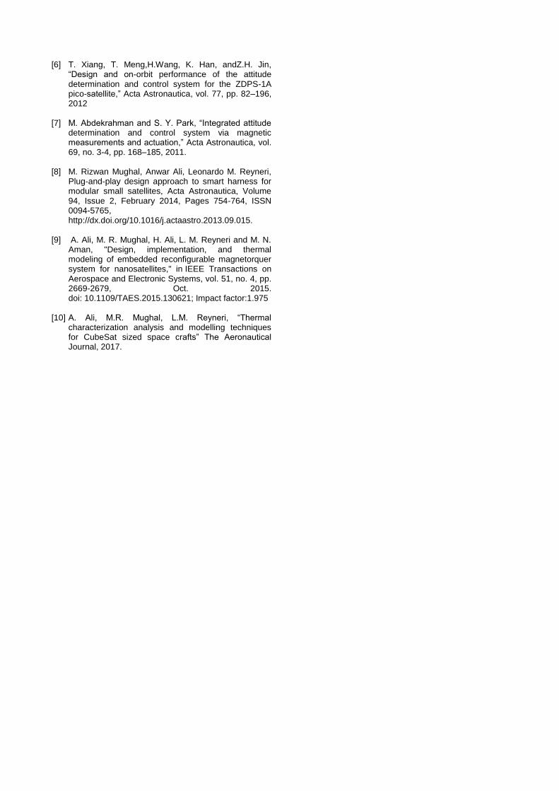
For the analysis, we have plotted generated torque (in Nm), T/P (in Nm/W), power (in Watt) consumption and current (Amp). It is evident from Fig.9 that by increasing the applied voltage,
the generated torque, and the torque to the power ratio decreases. Therefore, to conclude, it is recommended to operate the cylindrical magnetorquer at lower operating voltages so as to maximize the functional parameters.
Fig.9 Voltage Vs T/P Ratio, Torque, Power and current for cylindrical magnetorquer
Fig.10 shows the relation between applied voltage and torque, torque to power ratio and the temperature rise with changing voltage. It suggest that low voltage is more suitable for high torque to power ratio and low temperature of magnetorquer.
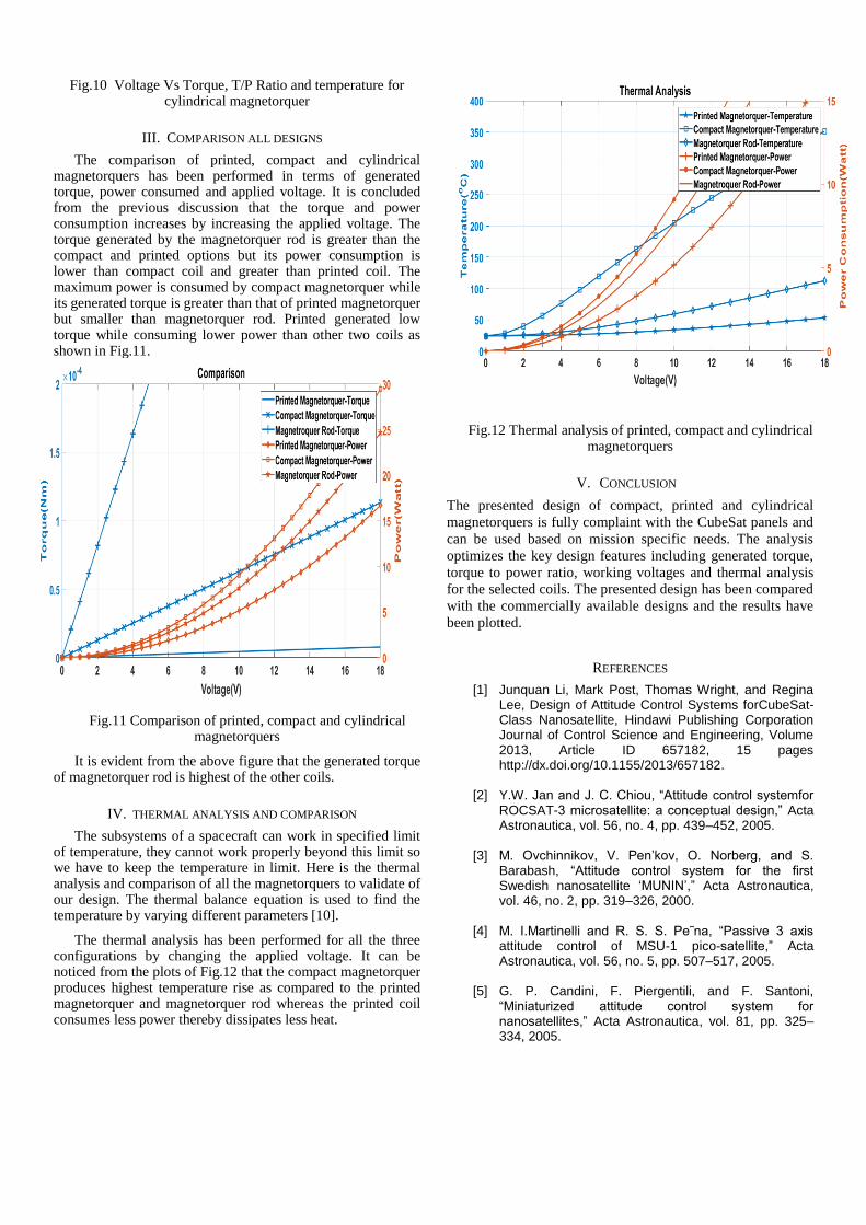
Fig.10 Voltage Vs Torque, T/P Ratio and temperature for cylindrical magnetorquer
III. COMPARISON ALL DESIGNS
The comparison of printed, compact and cylindrical magnetorquers has been performed in terms of generated torque, power consumed and applied voltage. It is concluded from the previous discussion that the torque and power consumption increases by increasing the applied voltage. The torque generated by the magnetorquer rod is greater than the compact and printed options but its power consumption is lower than compact coil and greater than printed coil. The maximum power is consumed by compact magnetorquer while its generated torque is greater than that of printed magnetorquer but smaller than magnetorquer rod. Printed generated low torque while consuming lower power than other two coils as shown in Fig.11.
Fig.11 Comparison of printed, compact and cylindrical magnetorquers
It is evident from the above figure that the generated torque of magnetorquer rod is highest of the other coils.
IV. THERMAL ANALYSIS AND COMPARISON
The subsystems of a spacecraft can work in specified limit of temperature, they cannot work properly beyond this limit so we have to keep the temperature in limit. Here is the thermal analysis and comparison of all the magnetorquers to validate of our design. The thermal balance equation is used to find the temperature by varying different parameters [10].
The thermal analysis has been performed for all the three configurations by changing the applied voltage. It can be noticed from the plots of Fig.12 that the compact magnetorquer produces highest temperature rise as compared to the printed magnetorquer and magnetorquer rod whereas the printed coil consumes less power thereby dissipates less heat.
Fig.12 Thermal analysis of printed, compact and cylindrical magnetorquers
V. CONCLUSION
The presented design of compact, printed and cylindrical
magnetorquers is fully complaint with the CubeSat panels and
can be used based on mission specific needs. The analysis
optimizes the key design features including generated torque,
torque to power ratio, working voltages and thermal analysis
for the selected coils. The presented design has been compared
with the commercially available designs and the results have
been plotted.
REFERENCES
[1] Junquan Li, Mark Post, Thomas Wright, and Regina Lee, Design of Attitude Control Systems forCubeSat-Class Nanosatellite, Hindawi Publishing Corporation Journal of Control Science and Engineering, Volume 2013, Article ID 657182, 15 pages http://dx.doi.org/10.1155/2013/657182.
[2] Y.W. Jan and J. C. Chiou, “Attitude control systemfor ROCSAT-3 microsatellite: a conceptual design,” Acta Astronautica, vol. 56, no. 4, pp. 439–452, 2005.
[3] M. Ovchinnikov, V. Pen’kov, O. Norberg, and S. Barabash, “Attitude control system for the first Swedish nanosatellite ‘MUNIN’,” Acta Astronautica, vol. 46, no. 2, pp. 319–326, 2000.
[4] M. I.Martinelli and R. S. S. Pe˜na, “Passive 3 axis attitude control of MSU-1 pico-satellite,” Acta Astronautica, vol. 56, no. 5, pp. 507–517, 2005.
[5] G. P. Candini, F. Piergentili, and F. Santoni, “Miniaturized attitude control system for nanosatellites,” Acta Astronautica, vol. 81, pp. 325–334, 2005.
[6] T. Xiang, T. Meng,H.Wang, K. Han, andZ.H. Jin,
“Design and on-orbit performance of the attitude determination and control system for the ZDPS-1A pico-satellite,” Acta Astronautica, vol. 77, pp. 82–196, 2012
[7] M. Abdekrahman and S. Y. Park, “Integrated attitude determination and control system via magnetic measurements and actuation,” Acta Astronautica, vol. 69, no. 3-4, pp. 168–185, 2011.
[8] M. Rizwan Mughal, Anwar Ali, Leonardo M. Reyneri, Plug-and-play design approach to smart harness for modular small satellites, Acta Astronautica, Volume 94, Issue 2, February 2014, Pages 754-764, ISSN 0094-5765, http://dx.doi.org/10.1016/j.actaastro.2013.09.015.
[9] A. Ali, M. R. Mughal, H. Ali, L. M. Reyneri and M. N. Aman, "Design, implementation, and thermal modeling of embedded reconfigurable magnetorquer system for nanosatellites," in IEEE Transactions on Aerospace and Electronic Systems, vol. 51, no. 4, pp. 2669-2679, Oct. 2015. doi: 10.1109/TAES.2015.130621; Impact factor:1.975
[10] A. Ali, M.R. Mughal, L.M. Reyneri, “Thermal characterization analysis and modelling techniques for CubeSat sized space crafts” The Aeronautical Journal, 2017.