Embed Size (px)
Citation preview

Guidelines for the Design of the Means of Access for Inspection, Maintenance and
Operation of Commercial Ships
April 2008
Guidance Note NI 537 DT R00 E
17 bis, Place des Reflets – La Défense 2 – 92400 Courbevoie Postal Address : 92077 Paris La Défense Cedex
Tel. 33 (0) 1 42 91 52 91 – Fax. 33 (0) 1 42 91 53 20 Email : [email protected]
Web : http://www.veristar.com

MARINE DIVISION
GENERAL CONDITIONS
������������������ �����������������
��������
� �� �� � �� ��� �� �� � � � �� � �!��"�� "# �� $ ��$ � �� �%� & # � ������'�� ( �) � ��'� *"# �� +� �!��"�,-� � � "# �!.� �%�!�"��'� *+/ .� �%�!�"��',-� �%� �'�� # �$ � ��� ) � �.� ��� "��!"���� �%� �'�� "�$ �� ��� $ ��"� �%� �"� ��� � "�0"# ����'�!�..�!"�) �.��# ����'�%"�����%������"��� ���+� '�",�& # �"# ���.�'1 ���"�� # ���2���) ���������� ���������'�"2� & # �"# ����$ ���"������ .�!�"����"� ������ �'� �'.�'�� & �"�� � ��� $ ��".�� �'� .�'�2� �'!.���'3 � ��0���'� 2# �) ��!��%" 2� ���..�'3 � ��3 2� �%% # ���� �' "�..�"��' � �%� �'�� "�$ �� �'�� �%� �'�� $ ��$ � �2� "# ���� ��.�"��� �'��'!�..�����4 ��$ 0�'"2� �� ������'�"2� �!# �� �& �..�# �����'��$ �$ �.�'� 2�0����'3 �.�3 ��'��0����'3 �$ ��'" ����"# ��& � ��� ���!��������"# ��� �!��"��� # ��� �!��"�5
• $ ��$ ��� ��'��$ ��.� # � �� �.� �%���!.� �%�!�"��'2�6 ����'!��7 �"� ��'���"# �����!�0�'" �*+� �.� ,-8
• � �� �/ ��"�%�!�"� 2��""� "�"��' ��'��� �$ ��" �%�..�& �'3 ��" ��'"��) �'"��' �*+/ ��"�%�!�"� ,-8• $ ��.� # � �� �3 � "�� �� � �� � # �� � �!��"�� �. �� $ ��"�!�$ �"� � �'� "# �� �$ $ .�!�"��'� �%� 7 �"��'�.� �'�� �'"��'�"��'�.� � �3 �.�"��' � ��� "�'���� 2� �'� $ ��"�!�.��� ��� ��.�3 �"��'� %��0� ��%%���'"� 6 �) ��'0�'" �� � # � �� �!"�) �"�� � ���� # ����%"��!�..�!"�) �.����%������"���� �+/ ��"�%�!�"��',�
� ���� # ��� �!��"��!�'��. ��$ ��) ���� ��) �!� ���.�"���"��/ .� �%�!�"��'��'��/ ��"�%�!�"��'� �!# �� � # �$ ��'�!�0$ �'�� �%�"�� 0�'�3 �0�'"� !��"�%�!�"��'8� # �$ � �'�� $ ��"� �!���"�� !��"�%�!�"��'2� "���'�'3 � �!"�) �"�� 8� �..�!"�) �"�� � �'�� ��"�� � �'!���'"�.� "# ���"�� �!# � � � ��!�0�'"�"��'� �'� �'�� �$ $ ��"�'3 � 0��' 2� �%"& ���2�' "��0�'"�"��'2�0�� ���0�'" 2�"� " ��'��"���. ��'�������
���� # ���'"��) �'"��' �0�'"��'����'�����2�������'����9 ��������%������"��� �+� ��) �!� ,��� # ��$ ��"���'�:���" ���$ �� �'"�"�) ����4 �� "�'3 � "# �� ��) �!� � � � # ����'�%"��� ��%������"��� � "# �� +/ .��'",���� �� � ������� ����� ��� ���� � ��� � ������� � � � �� � �� �� �� �� � � � � ��� �� �� ��� �� �� ������� � ���� �� ���� � � �� �� ���������� ���! ������ ����� "� ��# � � � ������ � � ��$ �%�� ��& ��� � � ��$ ' (�� ��������
) � �� � # �� � �!��"�� � �'��"# ����'��0���'�"����!�' �������� ��'� � '���& ��"��2����1 ��� �'� # �$ ; � �.����!# ��"���'3 2�< $ ��"� �'� � '�"; � ) �.��"��'2� / �' �."�'3 �'3 �'���2� / �'"��..��2� 7 �) �.���!# �"�!"2���'�%�!"����2� # �$ ���.���2� � �$ ���� ����2� / # ��"����� ��� � # �$ �& '��� & # �� ���� '�"� ��.��) ��� �%� �'�� �%� "# ���� �< $ �� ��� ���0$ .������.�3 �"��' ������"# ���'"��) �'"��' ��%�"# ��� �!��"��
���������
� ���/ .� �%�!�"��'�� �"# ���$ $ ��� �0�'"�3 �) �'����"# ��� �!��"��%����" �/ .��'"2��"���!��"��'���"�2�%�..�& �'3 ��) �� � ��� �" � � ��) ���� � �.�'3 � "# �� .�'� � $ �!�%���� �'� ��"�!.� � 9 � �'�� �� # ����%"��� �'� "# �� .�) �.� �%!�0$ .��'!���%���� '�"�"���" �� �.� ����$ ��"��%�"# �0��� # � ��$ $ ��� �0�'"�� ���$ �� �'"��������!.� ��'"�����'�"# ��/ ��"�%�!�"� ��'��$ ������!�..��"��' !�������'�"# ��� �!��"�; �� �3 � "���
� � � �� / ��"�%�!�"��'� � �!���������"���� "# �� � �!��"�� �.�'3 � "# �� �0�� .�'� � � � �"� ��"� �'���"�!.� � 9 � �'���# ����%"����'��& �"# ���%���'!��"��"# ���$ $ .�!��.��7 �"��'�.��'���'"��'�"��'�.�� �3 �.�"��' ����� "�'���� �
� � � �� ��� �� � ���� � * ���� � � � �� �� �� ������� �� � � �������� �� �� �� �� ���� �� � � �� �� + ���� � ���� � � ���$ � ,� ��� ��� ���� �� �� + ���� � �� � � ���$ � ���� � �� � �� � �� � �� �� � � ����$ � � ��� � � �� � ���$ � � ������ � � ������ � � � ���� �$ �� ������ ��- ������� � ���� �� ����� ����� � ���� �� � � � $ ���� �� �� � �
�� ���� # ��/ .��'"�� �"��3 �) ��"��"# ��� �!��"���..��!!� ��'���'%��0�"��'�'�!� ����%���"# ��$ ��%��0�'!���%"# ����4 �� "���� ��) �!� �
���������
� � .��� ���� ��� ,� � �� ��� � ��� � ��� � ��� ��� ���� �� � � � �� �� � � ����$ � ��/ �� ���� � ���� � ��� ��� �� �� � ���� � �� ���� � ��� ������ �� �� �� � ����� � � �� ������$ � ������* ��� ��� � � �� ���� ���� ������ / �� � ��� - �� � � �� ���� � � ��$ � �� �$ � ���� �� �� �� �� � �� � � �� �� ��� ���� �� ����� ��� �� - � �� �� � �� � ����������� � �� �� � � ��$� ��� * � � /
/ �00�""�� � !�' � "�'3 � �%� $ �� �'�.�"�� � %��0� "# �� �'�� "��� !�'"����"�� "�� "# �� ��) �.�$ 0�'"� �%� "# � ���!�0�'" �
� � � .��� �� � � ����$ � � ��$ � �� � 0 � ��� ��� � �� ��� � �$ � ��� ��� ��� ���� � �� � ������ ���� �� �� � ��$ � �� ������� ���� �� �� �� ��� �� ����� ���� � �������� ���� ��� ��� � ����$ 1� ������������ �
� � �.�� # ��� ��) �!� ��%�"# ��� �!��"������!���������"����$ ��%� ��'�.�� ��) ���� ��!!����'3 �"��"# ��/ �����%"# �! ��%�"# ����0��� ��%�"# ���'"��'�"��'�.�� �!��"��'��%�/ .� �%�!�"��'�� �!��"�� �*��/ � -�
� �.��� ��� � ������ �� �� ��� ��� � ����$ ����� �� ��� ��- ���� �� ������� ������2��� � ����$ ��� �� � ���� �* $ �� �$� � ���� � � � ��� � ����� �� � ��� � � � � �� �� ��� ��$ � ����� � � ������ � ���� ���� � � ���� ���- � � �� �2� �� � �������� ������ �
��������
���� # ��� �!��"�2��!"�'3 ������%���'!��"���" �� �.� 5
• ��) ��& �"# ��!�' "��!"��'�����'3 �0�'" ��%� "# �� � '�" �� � # �& '��'�"# ����!�0�'" � $ �� �'"������ "# �/ .��'"8
• !�'��!" � ��) �� ��"�"# ��$ .�!���%�"# ����!�' "��!"��'8• !.� � �� '�" ��'���'"�� �"# ����!.� ��'��" �� �3 � "��8• ��) �� �$ ������!�..��"# ��� '�" ��'� ��) �!��"��'�"��"# �"�"# ����4 ����0�'" �%���"# ��0��'"�'�'!���%�!.�
����0�"�
�� ����������� ��� ��� � �� ��� ��� � ����$ �� ��� � � ��� ���$ �� ������ � � ������ �� � ��� �� �$ ���� � ���� ��� ����� ��� ���2������ ��� ��� � ���$ � ��� �* ���� ��- ��
��������)
) � .� �� �� � � ����$ � ���� � �� � �� � �� ��� ��� � � � ������� � �� �� � ����� �� * �� �� �� ��� �� � �� � ��� � * ��- ���� �* �����- �� ���� ��� � ����$ ��� �� * ���������� � ���� ���� ���� ������$
) � �.��� ������� ������ ��� � � �� �* $ ��� ��� � ����$ �� � �� � ������ �) �� �����* � ���������� ����� ����� ���� �������� ��� � � �������� � �� �� + ���� �� � ��� ��� ��� � � �� �� � �� �� � � �� � ���� � � � �� ������� � �� �� �� � �������� �� ��� �� � � �
��� � ������ ���,� �� �� � � ����$ � � � �� � �� �� ��- �- �� ��� ��$ � � � �/ � �������- � �� � �� �� � �� �- �,� * � ��� ��- ,� �� � � ���� ��� ����� ������ ��/ � ,������ �������� ��� � ������ ��� ��� ��+ ���� �� ������� �������� �,������ ��������$�� ��� � �$ � � ������� ,� ��� � ����� �� * �� � ��� � ���* ��� � �� �� � � �� ���� � ��� � ��� � ����� ������ � ����� �� * ��� �� ��� �� ��� ������ � ���� �� ���2� ��� � �� ������$ �� �� � ��$ ,� ����� � � � ���� ��� � �� � � �,�� ��� � ��� ���� �� ��� ��+ ����� ��� ���� ����� �� � ��� ���,���� � ������� ���� �������-
) � � .� �� �� � � ����$ � � � �� � �� �� � ������� �� �� ����� ������ � �� �� � � �� � �� ���- � � � �� + ���,� �� �� � � ����� �� ��� ���� ������� � � �� ��$ �� ��� ���� �� �� �- �,��� ���* ���- ��� ���2��� � ������� � � �� �* ����$ �� ���� �� � ���� ��* � ��� ��,���� � �������$
) � �� � # �� � ��) �!� ��%� "# �� � �!��"��!�''�"�!���"���'����.�3 �"��'������'3 ��'� "# �� � �!��"�����!�' "�"�"���'�& ����'"���%�$ ��$ ����$ ���"��'2�����'���'����$ �� �'"�"��'� �"�%��"# � �'�"# ��� �.� 2��%��'�� � '�"2��4 ��$ 0�'"���0�!# �'���2� !�0$ �"��� �%"& ���� �%� �'�� ��"� ��� �"# ��� !�0$ ����.�� !�'!�$ " � "# �"� # � � ���'� ����!"� "�� �'� ��) ������"# ��� �!��"��
��������3
3 ���� # ��� �!��"���!!�$ " �'���� $ �' ���.�"��%���"# ��� ���%��'%��0�"��'���.�"���"���" �� ��) �!� �& # �!# �& � '�"�$ ��) �����%���"# ��$ ��$ � �����"# ��� �!��"�����& �"# ��" �� � "�'!��
3 � �.�� ��� ��� ������� �� ��� ��� � ����$ ���� � ���� ��� ������������ �� �- ��� � ��� ��� �� �� ��� ��� �* ���� ��� �������� � ���� � ��* �$ � � ��� ���* ��� �� �� �0 � ����� � � ��� ���� �� � �� � � �� � �� �� � � �� �� � � ����$ ,� ��� � ���* ����$�� � ��� � ��� ����������� ���� ���� ��� �������� �� ��� ���� � � ���� � ���� ��� � � ���� ��� �������� ����- ���� � ���� ��� �� �- �,�� �� ��� �� �� � � ������� ����� �� ���� ���� � ����* ��� � * 4������� ���� ���� � � �� ���- � ���� � � � ���%5 ,6 6 6 (��� �� ,���� ��� ���� �2�� � � �� � ��� ��� ��� ��- �������� ���- � ��� � �� ��� ��� � � � ��� �%5 6 6 ,6 6 6 (��� ����� �� ������ ���� �� ���� �� ��� ���* � ���� ����� ��� � ��
�� �� � � ����$ � * ���� ��� � ���* ����$ � � �� ��� ������ � ���� �� �0 � ������� �� � � � � � �� ��� ��- � �� � � � � � ������ �,�� � � � � � � �� ��,� �� � � � � � � �� � � ���� �,� �� � � � ��������� �� � � �� ��� �� ������� � ��� � ��� �� ������ � � ����� ������ ��� �� �� ����- ���� ����
��9 �����..�!.��0 �����"�����$ �� �'"���"��"# ��� �!��"���'�& ��"�'3 �& �"# �'�"# ����0�'"# ��%�"# ����"��& # �'�"# �� ��) �!� �& ���� �$ $ .�������*�%�.�"��-�"# ����"��& # �'�"# ���) �'" �& # �!# �������.�����'��%�& ����%�� "�1 '�& '�"�"# ��/ .��'"2��'���'��!.��0�& # �!# �� �'�"� ��$ �� �'"��� # �..�������0���& ��) ����'���� �.�"�.���������
��������7
7 ���� �4 �� " �%���� ��) �!� �����"������'�& ��"�'3 �
7 � � .� ���� ��� �� �� ������� � �� �� �� � � ����$ � ���� ���� ������ �� � � � ��- � �� �� �� ��0 � �� ��� � � ������� � � ���- ����- ��� ��� �� ���� ���$ ��� ���$ �� �$ � 8�� ��������� ����,� � ���� ���������,���� �� ��� � � ��� ��4� � ������ ��� �� �� ��� �� �� ������������5 �� ���� �� ��
7 � ���� # ��!.� �3 ��'"���"��"# ��!�'!��'���� '�" ��'��"# ��$ ��) ��� .��� ����!��"�%�!�"� ���0��'�) �.����'"�."# �� ��"�� �%� �%%�!"� �%� "# �� '�"�!�� � ���� �!!����'3 � "�� = ���� # ������) �� ����!"� "�� !�0$ .��'!�� & �"# � ��9 �# ������) ���'����"�!.��> �# ����'����
��������5
5 ���� # ��� ��) �!� ��%�"# ��� �!��"�2�& # �"# ���!�0$ .�"������'�"2��') �.) ��"# ��$ ��0�'"��%�%����$ �'���!��$ "�%�"# ���') ��!���'��"# �����0��� �0�'"��%�"# ���< $ �' � ��'!������
5 � �.�# ���� � ���� � � ��� ������������ �� ��� �� ���- � ��* $ �������� ��������� �� ������ ��� ��� ���� � ����* ����- �� ����� �
5 � � .� �� �� ���� � � � � �� + ���� � �$ � * �� � � � � ��� �� � ��� �� �� ������ � � �� �.� �$ � ���� � � ��� � ���� �� ��� �� � �� �� � ���� �� ������ ���� �� �$
ARTICLE 9
9 � �� � # �� ��!�0�'" � �'�� ��"�� $ ��) ����� "�� ��� $ ��$ ����� ��� "# �� � �!��"�� %��� �" � � ��) �!� 2� �'�� "# ��'%��0�"��'��) ��.��.��"��"# ��� �!��"�2�����"���"���� �!�'%���'"��.��? �& �) ��5
• / .��'" � # �) �� �!!� � "�� "# �� ��"�� "# ��� # �) �� $ ��) ����� "�� "# �� � �!��"�� �'�2� ����'3 � "# �� $ ������ �%!.� �%�!�"��'� �%� "# �� � '�"� %��� "# �02� "�� "# �� ���� � � ������ �� ���� !�' � "�'3 � �%� ��) ��� ��$ ��" � �'�!��"�%�!�"� �& # �!# �# �) �����'�$ ��$ ������"��'��"�0�����"# ��� �!��"��%���"# ��!.� �%�!�"��'��%�"# ��� '�"�8
• !�$ �� �%� "# �� ��!�0�'" � 0���� �) ��.��.�� %��� "# �� !.� �%�!�"��'� �%� "# �� � '�"� �'�� �%� �) ��.��.�� ��) ����$ ��" � !�'� ��� # �'���� �) ��� "�� �'�"# ��� / .� �%�!�"��'� � �!��"�� ��0���� �%� "# �� �'"��'�"��'�.� �!��"��'���%�/ .� �%�!�"��'�� �!��"�� �*��/ � -��'�!� ���%��"# ��� '�"; �"��' %����%�!.� 8
• "# ����"����.�"�) ��"��"# ���) �.�"��'��%�"# ��� �3 � "��2�"��"# ��!.� � � $ �' ��'��'��"��"# �� ��) ��� "�"� ��%"# ��� '�" �����$ � ����'�"����/ � ��!!����'3 �"��"# ��� �!��"��'�& ��1 �'3 ���.� 8
• "# ��!��"�%�!�"� 2���!�0�'" ��'�� �'%��0�"��'� ��.�"�) �� "�� "# �� � '�" �!.� ��� & �"# � "# �� � �!��"��0�������) ��& �������'3 ���/ � �����" ��'�������� !.� ����$ �'��������%�"# ��!�'!��'���3 �) ��'0�'"�.�����'"���3 �) ��'0�'"�.���"# ���"�� �����%���/ ���"�# �) �'3 ����� ��!"��'�
� # ����!�0�'" ��'����"������ ����!"�"����%�.��0�'�3 �0�'"�$ .�'�
��������6
6 � �� �'�� ��.��� ��� # ��"!�0�'3 � �'� "# �� $ ��%��0�'!���%� �" � � ��) �!� � ��� "# �� � �!��"�� ��� �'3 � %��0��'�) �'"�'�"���� �'��.��%��� ����.������������'��"# ��!�'"��.��%�"# ��� �!��"�� # �..�������0���'�"�"����������!# ��%�!�'"��!"�
��������
����'�!� ���%���) ��3 �'3 ��$ �'��' �����'3 � ��) �� ���"& ��'�"# ��/ .��'"��'��"# ��� �!��"�; � ��) ����2�"# �� �!��"��0����� �3 '�"���'�"# ����%��" � ��) ���� ��"�"# ����4 �� "��%�"# ��/ .��'"�
� ���( � �3 ���0�'" ��%���"�!# '�!�.�'�"������"& ��'�"# �� / .��'"��'��"# �� � �!��"��!�'���� ��0�""�����"# ��� �!��"��"��"# ����) �!���%��" �����'����) � ����/ �00�""���
���������
��������( � $ �"� ��) ���"# ��� ��) �!� �!���������"������.�3 �"��'��%�6 �) ��'0�'" ������ � ���& �"# �'�"# �%��0�& ��1 ��%�"# ���$ $ .�!��.���3 ���0�'" �& �"# �"# ��� "�"� 2��'"��'�"��'�.�/ �') �'"��' ��'��'�"��'�.���.� �
� � ���( � $ �"� ���� �'3 ���"��%�"# ��$ ��0�'"��%�"# ��� �!��"�; ��') ��!� ����"# ��/ .��'"����� ��0�""���"��"# �/ ���"��%�7 �'"����2����'!��
� � �.�# �� ���� �� � � ��� �� ������ ��� ��� ����: ��������� �� ���� �� �� ��� ������ ��� ������� �� ��� ��� � ����$���� �2��� � ����$ � � � * � ����� � �� � ��* ������� �,� * $ � �� ���� ��* ������ �� ,� ��� �� �� � �� ���� �� ��- � �� � �� ���* ������� �� ���� 9 9 3 � � �� ��$ � � ���� �� �$ � � � � � ������ �� � �� ��.������ ���� �� ���� � �� �� �� ������* ��� ������ ��� � ����$ ���� ��� ���������� � ����* ��- � ������ �* $ ���- ��� � ����
���������
� � .��� �� �� : ��������� �� ���� �� ��� �� ���� ��� �� �� � � ����� ������� ��� � * ��- ���� �� � * ��� ��- � �� - ��� ���� �� � � ����$ � ��� � �� �� ������,� �� � �� �� �2��� � �� �� � � ���� � �� ��� ��� ��� ������� �,� � ����� ���� ,� ���� � ,�� �� ���� �� �� � ��� ����2� ��� � �� ���� � ���� �� # ���0������) �������'�& ��"�'3 ����0�"��.��3 ���0�'"�
� � ���� # ���') �.���"���%��'�����0���� "�$ �.�"��' ��%�"# ��$ �� �'"�6 �'���.�/ �'��"��' ���� �'�"��%%�!"�"# �) �.���"���%�"# ����0��'�'3 �$ ��) � ��' �
� � ���� # ����%�'�"��' �# ����'��"�1 �� $ ��!���'!���) ����'����%�'�"��' � ��) �'3 � "# �� �0��$ ��$ � ��& # �!#0����$ $ �����'��"# �����!�0�'" �� �������"# ��� �!��"��

NI 537
April 2008 BUREAU VERITAS 1
TABLE OF CONTENTS
INTRODUCTION AND HISTORY OF THE GUIDELINES 3
1. THE METHOD 4
1.1. User feedback 4
1.2. An ergonomic approach: anthropometric analysis of the
Means of Access (MAs) 4
1.2.1. Ergonomics 4
1.2.2. Anthropometry 5
1.2.2.1. Definition 5
1.2.2.2. Anthropometric design 5 1.2.2.2.1. Population description 5 1.2.2.2.2. Constraint definition 6 1.2.2.2.3. Environmental considerations 7 1.2.2.2.4. Scope of guidelines and means of access considered 7 1.2.2.2.5. Design strategies 7
1.2.2.3. Guidelines development stage 8
2. THE GUIDELINES: REQUIREMENTS FOR THE DESIGN AND
USE OF THE MEANS OF ACCESS (MAS) 9
2.1. Walkways, guardrails and handrails 9
2.1.1. Walkways and platforms 10
2.1.1.1. General requirements for walkways 10
2.1.1.2. Requirements for walkways – clearance 11
2.1.1.3. Requirements for walkways – around webframes 12
2.1.1.4. Requirements for low height structures 13
2.1.1.5. Requirements for handrails – 1 14
2.1.1.6. Requirements for handrails – 2 15
2.1.2. Handles 16
2.1.2.1. Requirements for handles 16

NI 537
BUREAU VERITAS April 2008 2
2.1.2.2. Requirements for handles – clearance 16
2.2. Openings 17
2.2.1. Vertical openings 18
2.2.1.1. Requirements for vertical openings – design 1 18
2.2.1.2. Requirements for vertical openings – design 2 19
2.2.1.3. Requirements for vertical openings – design 3 20
2.2.1.4. Requirements for access to vertical openings 21
2.2.2. Horizontal openings 22
2.2.2.1. Requirements for horizontal openings – other than access openings 22
2.2.2.2. Requirements for horizontal openings 23
2.3. Vertical ladders 24
2.3.1. Requirements for embedded steps 24
2.3.2. Requirements for ladders with curved stringers 25
2.3.3. General requirements for vertical ladders 26
2.3.4. Requirements for the arrangement of vertical ladders – 1 27
2.3.5. Requirements for the arrangement of vertical ladders – 2 29
2.3.6. Requirements for safety cages 30
2.4. Inclined ladders or stair ladders 31
2.4.1. General requirements for inclined ladders 31
2.4.2. Detailed requirements for inclined ladders 32
2.4.3. Requirements for the arrangement of inclined ladders 33
2.5. General requirements, advice and best practice 33
2.5.1. Marking of the means of access 33
2.5.2. Slip resistance 35
2.5.3. Training 37
2.5.4. Maintenance 37
REFERENCES 38

NI 537
April 2008 BUREAU VERITAS 3
Introduction and history of the guidelines
These guidelines aim to provide detailed information on the design features that should be included, when considering the means of access of a ship, in order to reduce the risk of slips, trips and falls. In 2004 the International Maritime Organisation adopted amendments to SOLAS Reg.II-1/3-6 on technical provisions for access to and within spaces in and forward of the cargo area oil tankers and bulk carriers [Resolution MSC.151 (78)] and amendments to the Technical provisions for means of access for inspections (Resolution MSC.158 (78)], for entry into force on 1st January 2006. In response to this, IACS published Unified Interpretations, namely IACS UI SC 191 for the application of amended SOLAS Regulation II-1/3-6 and revised Technical Provisions for means of access for inspections. Thus, these interpretations provide technical specifications with particular dimensional requirements for ensuring the safe access of the different compartments of oil tankers and bulk carriers. However, these interpretations sometimes remain too general and do not cover the spectrum of issues one can face when using the means of access. Moreover, they only deal with oil tankers and bulk carriers although the other types of ships should also be provided with safe means of access. Therefore, Bureau Veritas developed these guidelines to help those involved in the design of ships ensure that the means of access for inspection, maintenance and operation are safe and effective. The guidelines set out the ergonomic standards that will ensure that all users of the ship from seafarers to part time users such as shipyard workers and surveyors, can safely access the ship’s compartments. The objective of these guidelines is not to replace the existing regulatory requirements for the design of the means of access: it does not provide interpretations of the IMO regulations and technical provisions, nor of the IACS unified interpretations. On the contrary, it provides designers and ship owners who wish to go further in the prevention of occupational accidents with a means to do so. Furthermore, while the IMO definition of means of access is restricted to those used for inspection, in this document this phrase describes the means of access for inspection, maintenance and operation of the ship as well.

NI 537
BUREAU VERITAS April 2008 4
1. The method
The method employed to develop guidelines relies on two fundamental ideas:
1. When designing the workplace, high consideration has to be given to fitting the product to the user and the task they have to complete. In this case, fitting the ship or more precisely the permanent means of access, to the seafarer whose duties include maintenance, ship operation and emergency evacuation.
2. If the designers want the product to fit the user and the task, they have to integrate relevant user-feedback in the design process.
In this respect, the requirements presented in the guidelines result from on one hand, feedback from experienced surveyors as well as shipboard observations and, on the other hand, ergonomic analysis of the means of access.
1.1. User feedback User feedback techniques allow to gather a substantial amount of information from the people operating the ships in order to focus on the most relevant and practical issues that arise from the Means of Access (MAs) onboard. Thus, instead of making assumptions about the suitability and riskiness of the MAs, it is aimed to confront opinions from the different users. For this purpose, three different tools to get the most complete feedback as possible are used. These are:
� Free and semi-structured interviews; � Personal visit to ships; and � Questionnaires.
The first two tools provide some qualitative data whereas the questionnaires allow a quantitative analysis to be completed.
1.2. An ergonomic approach: anthropometric analysis of the Means of Access (MAs)
1.2.1. Ergonomics There are five fundamental criteria in ergonomics theory that ensure a successful match of the product, the user and the task [Pheasant, 2006]. These are:
� Man-machine interface (e.g. functional efficiency); � Ease of use; � Comfort; � Health and safety and; � Quality of working life.

NI 537
April 2008 BUREAU VERITAS 5
In order to ensure the guidelines, and therefore any design that follows them, comply with these criteria, the principles of the user-centred design are employed. User-centred design should:
� Be empirical and iterative; � Be participative (end users are active participants); � Take into account human diversity; � Be system-oriented; � Be pragmatic.
These guidelines are developed using anthropometric analysis that matches all the principles above.
1.2.2. Anthropometry
1.2.2.1. Definition Anthropometry is the branch of ergonomics dealing with the measurement of the human body. Data is collected for the size, shape, strength, mobility and flexibility of different populations and genders. From the results of an anthropometric analysis, many of the technical requirements for the design of user-centred MAs onboard ships may be extracted. According to Pheasant, the objective of anthropometrics is to choose the best compromise dimensions for equipment that will be employed by a range of users [Pheasant, 2006]. In order to optimize such compromises, three types of information are required:
� The anthropometric characteristics of the user population; � The ways in which these characteristics might impose constraints upon
design; � The criteria that define an effective match between the product, the user
and the task.
1.2.2.2. Anthropometric design
1.2.2.2.1. Population description The population aimed at is mainly composed of seafarers. As the ships can be operated by crews of both sexes and coming from any region of the world, the complete international population of seafarers is studied. Most anthropometric variables conform quite closely to the normal distribution (at least for reasonably homogeneous populations) [Pheasant 2006]. Thus, population

NI 537
BUREAU VERITAS April 2008 6
measurements are described with the percentiles of the distribution. For instance, for the measurement of men’s stature, considering the limiting user as the tallest of the 95th percentile of the population implies that 5% of the population is taller than this man. However, specific anthropometric data about the seagoing population is not available. Therefore, data for international populations are used. The anthropometric data use the fifth percentile Japanese woman for the ‘lower’ limiting users and the 99th percentile American man for the ‘upper’ limiting users. The effect of clothes and equipment on the dimensions of members of the population is also considered. It is assumed that all of them wear protective boots, working clothes, gloves and a protective helmet. Furthermore, when this is required by the situation analysed, the seafarers are assumed to wear specific additional equipment such as breathing apparatus for the study of emergency scenarios.
1.2.2.2.2. Constraint definition These guidelines are developed with the following constraints in mind:
• Clearance: The means of access must provide adequate access and circulation space. Handles must provide adequate apertures for the fingers or palm. These constraints are used to determine the minimum acceptable dimension.
• Reach: The means of access must be within reasonable proximity of the user. These dimensions are usually fitted to the smallest member of the population and they determine the maximum acceptable distances. • Posture: When using the means of access user must be able to maintain a suitable posture. Postural problems tend to be more complex than problems of clearance and reach, since posture is almost certainly affected by more than one dimension of the means of access.
These constraints are then used to develop the guidelines. This process ensured the characteristics of the means of access are designed for the limiting user and a defined area of common fit is provided.

NI 537
April 2008 BUREAU VERITAS 7
1.2.2.2.3. Environmental considerations These guidelines take into consideration the environments in which the MAs are placed onboard vessels. It is essential to take into account the marine environment since it also determines the way MAs’ design should be addressed, e.g. the corrosive atmosphere and the motions of the ship.
1.2.2.2.4. Scope of guidelines and means of access considered These guidelines address the walkways, guardrails, handrails, platforms, vertical openings, horizontal openings, vertical ladders, and stair ladders or inclined ladders. These means of access are identified as covering the vast majority of slips trips and falls. In addition to these MAs, general requirements and advice are offered on the marking of the means of access, slip resistance, training and maintenance.
1.2.2.2.5. Design strategies Each type of means of access implies scenarios depending on the environmental conditions, the tasks to perform and the seafarers’ physical characteristics (body measurements and strength). Thus, different design strategies have to be employed for these different scenarios. Below are examples of design strategies that are adopted in the development of these guidelines: • For the walkways, tunnels and corridors:
� Obstructions should be clearly visible and clearance around them should
be sized for the largest user; � Width of passageways should be designed for the largest user; � Handrails, treads and guardrails should be designed for common fit. � Walkways, tunnels and corridors should be large enough to allow the
evacuation of an injured crewmember on a stretcher.
• For the openings, hatches and manholes:
� The vertical and horizontal openings should be designed for access of the largest user. People with dimensions higher than this percentile must be advised of this. A person wearing breathing apparatus should pass through easily;
� The handles, treads, steps, guardrails and other arrangements for safe access to openings and hatches should be sized for common fit;
� Markings of openings (especially horizontal openings) should be clearly visible;
� The openings should be large enough to allow the evacuation of an injured crewmember on a stretcher.

NI 537
BUREAU VERITAS April 2008 8
• For the ladders, stairways and inclined ladders:
� Design for the heaviest user to be able to climb; � Design platforms for the largest user; � Design for the smallest and the largest users to comfortable climb the
rungs of a ladder; � The handles, treads, steps, handrails, guardrails and other arrangements
for safe access to ladders should be sized for common fit.
1.2.2.3. Guidelines development stage Considering the design strategies adopted and all the constraints and requirements identified, the objective is to find the best designs of MAs by trying to reproduce the real life working situations onboard. Multiple drawings used in order to model the interactions between the seafarers and the MAs. Four environments were modelled 3-dimensionally, grouping the four main types of MAs: walkways, openings, vertical ladders, and inclined ladders or stair ladders. 3-D manikins were used to calculate the dimensions and shapes of the MAs.

NI 537
April 2008 BUREAU VERITAS 9
2. The Guidelines: requirements for the design and use of the Means of Access (MAs)
The guidelines are presented in this section and gather both dimensional requirements and practical advice for the design, use and maintenance of the MAs. The MAs are grouped by type. However, some points have to be made clear to prevent the reader from misinterpreting the focus of these guidelines:
� These guidelines deal with ships in general, whatever their size or their type. They provide the shipbuilders and shipyards with some ergonomic requirements and advice that are not specific to determined areas. However, some remarks are made about the applicability of the requirements to specific parts of the ship.
� As specified in the introduction, these guidelines are not meant to
describe how to apply the IMO regulations about the means of access for inspections and the unified interpretation from IACS. They complete these regulations by introducing the concepts of ergonomic/anthropometric design made to ensure safety and comfort of the personnel using the means of access.
� The technical requirements provided in these guidelines are based on
purely ergonomic principles. Consequently they are not meant to replace neither structural requirements based on mechanics and hydrodynamics nor technological analysis.
2.1. Walkways, guardrails and handrails This section focuses on the design of the walkways or passageways wherever they are situated. The requirements for the guardrails and handrails are also applicable to any of the rails onboard (the rails presented in the following sections should comply with these requirements as well). Note: There is a distinction to be made between a handrail and a guardrail. The former is designed to help people keep their balance while walking (e.g. due to ship motions or obstacles), while the latter is designed to prevent people from falling from a height.

NI 537
BUREAU VERITAS April 2008 10
2.1.1. Walkways and platforms
2.1.1.1. General requirements for walkways
Figure 1: Requirements for walkways (general)
Dimension IMO-IACS requirements Guidelines requirements
A Distance below overhead structure 1600 mm � A � 3m 2020 mm � A �3m
B Ramp inclination angle - B �15°
C Guardrail height (when one
side at least of the passageway is open)
C = 1000 mm C around 1200 mm
A
B
C
����������
NI 537
April 2008 BUREAU VERITAS 11
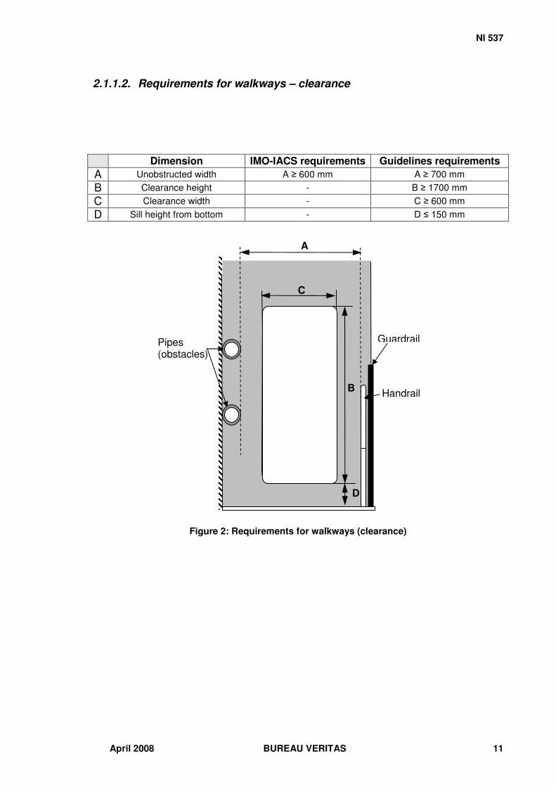
2.1.1.2. Requirements for walkways – clearance
Figure 2: Requirements for walkways (clearance)
Dimension IMO-IACS requirements Guidelines requirements A Unobstructed width A � 600 mm A � 700 mm B Clearance height - B � 1700 mm C Clearance width - C � 600 mm D Sill height from bottom - D � 150 mm
Pipes (obstacles)
A
C
B
D
Handrail
Guardrail

NI 537
BUREAU VERITAS April 2008 12
2.1.1.3. Requirements for walkways – around webframes
Figure 3: Requirements for walkways (webframes)
Dimension IMO-IACS requirements Guidelines requirements
A Width (for going around vertical webframe) A � 450 mm A � 600 mm
B Handle length - B � 600 mm
A A
A
B Webframe
Gap
Handrail

NI 537
April 2008 BUREAU VERITAS 13
2.1.1.4. Requirements for low height structures
Some areas such as double bottom ballast tanks and specific places in fore and aft peaks cannot provide sufficient height for a standing inspection. However, a minimum height for overhead obstructions is required for crawling safely:
Figure 4: Requirements for low height structures
Dimension IMO-IACS requirements Guidelines Requirements
A Distance below overhead obstructions when crawling - A � 1000 mm
Obstacle
A
A A

NI 537
BUREAU VERITAS April 2008 14
2.1.1.5. Requirements for handrails – 1
Figure 5: Requirements for walkways
Dimension IMO-IACS requirements Guidelines requirements A Unobstructed width A � 600 mm A � 700 mm B Top handrail height B = 1000 mm B = 1000 mm
C Intermediate rail height C = 500 mm C � 540 mm D Distance between stanchions D � 3m D � 1500 mm
E Distance between stanchions across gap (top and middle
rails connected) E � 550 mm E � 550mm
F Vertical clearance - F � 100mm G Lateral clearance - G � 60 mm
D
A
C
B
G F
E
G

NI 537
April 2008 BUREAU VERITAS 15
2.1.1.6. Requirements for handrails – 2
Figure 6: Requirements for handrails
Dimension IMO-IACS requirements Guidelines requirements
A Handrail diameter - 30mm � A � 60mm 45 mm recommended
B Gap between handrail sections B � 50mm B � 50 mm
C Outside radius of the bent part C � 100 mm C �100 mm
D Distance between stanchions across gap (top and middle
rails not connected) D � 350mm D � 350mm
A
B
D
C

NI 537
BUREAU VERITAS April 2008 16
2.1.2. Handles
2.1.2.1. Requirements for handles
Figure 7: Requirements for handles
2.1.2.2. Requirements for handles – clearance
Figure 8: Requirements for handles (clearance)
Dimension IMO-IACS requirements Guidelines requirements
A Handle diameter - 30 mm �…A � 50 mm
35mm recommended
B Handle outside radius of the bent part - B � 25 mm
50 mm recommended C Handle depth - C � 80 mm
Dimension IMO-IACS requirements Guidelines requirements A Vertical clearance - A � 370 mm B Lateral clearance - B � 95 mm
A B
C
A
A
B

NI 537
April 2008 BUREAU VERITAS 17
2.2. Openings This section deals with openings in general: manholes, hatches as well as light openings and ballast management openings. The vertical and horizontal openings used as means of access should be provided with relevant handles and steps to allow safe use (both sides of the opening should be fitted). The clearance around an opening should ensure ease of use and with no obstruction. For horizontal openings, light openings and other openings that are not used as means of access, particular attention should be paid to prevent people from falling into them. This could be done, depending on the case, by designing relevant covers for hatches and manholes, locating the opening in an appropriate place and designing protective bars and guardrails around them. The access openings should not be obstructed by pipes unless the clearance is sufficient for a safe use, as specified in the following tables and figures. For some locations onboard, such as ballast tanks, peaks, double hull spaces, the structures to be accessed should be provided with at least one exit with unobstructed openings. Note: These guidelines do not address the design of light openings (openings used to light indoor compartments). However, it is necessary to consider the risk of falling into this type of opening. Their size, location and arrangement should be set in accordance with this risk. In some cases such as shown in figure 9 below, basic guards can prevent people from falling in a light opening.
Figure 9: Open hatch guards

NI 537
BUREAU VERITAS April 2008 18
2.2.1. Vertical openings
2.2.1.1. Requirements for vertical openings – design 1
Figure 10: Requirements for vertical openings – Design 1
Dimension IMO-IACS requirements Guidelines requirements A Sill height A � 600 mm 400 mm � A � 500 mm (1) B Vertical opening height B � 800 mm B � 950 mm C Vertical opening width C � 600 mm C � 750 mm D Corner radii D = 300 mm D � 375 mm
I Vertical handle lateral distance to opening - I = 50 mm
J Vertical handle length - J � 600 mm K Horizontal handle length - K � 500 mm
L Horizontal handle distance above opening - 50 mm � L � 200 mm
(1) This dimension is based on ergonomics and does not pretend to replace the already existing safety requirements.
J B
A
K
D
C
I
L

NI 537
April 2008 BUREAU VERITAS 19
2.2.1.2. Requirements for vertical openings – design 2
Figure 11: Requirements for vertical openings – Design 2
Dimension IMO-IACS requirements Guidelines requirements A Sill height A � 600 mm 400 mm � A � 500 mm (1) E Vertical opening height E � 850 mm E � 950 mm F Vertical opening width F � 620 mm F � 750 mm G Radius upper half G = 310 mm G � 375 mm H Radius lower half H = 200 mm H � 265 mm
I Vertical handle lateral distance to opening - I = 50 mm
J Vertical handle length - J � 600 mm K Horizontal handle length - K � 500 mm
L Horizontal handle distance above opening - 50 mm � L � 200 mm
(1) This dimension is based on ergonomics and does not pretend to replace the already existing safety requirements.
J E
A
K
I
F
G
H
L

NI 537
BUREAU VERITAS April 2008 20
2.2.1.3. Requirements for vertical openings – design 3
Figure 12: Requirements for vertical openings – Design 3
Dimension IMO-IACS requirements Guidelines requirements
I Vertical handle lateral distance to opening - I = 50 mm
J Vertical handle length - J � 600 mm K Horizontal handle length - K � 500 mm
L Horizontal handle distance above opening - 50 mm � L � 200 mm
M Vertical manhole diameter M � 600 mm M � 750 mm N Sill height N � 600 mm N � 500 mm
J M
N
I
L
K
NI 537
April 2008 BUREAU VERITAS 21
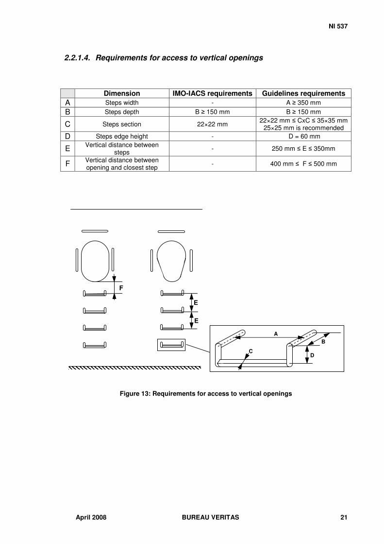
2.2.1.4. Requirements for access to vertical openings
Figure 13: Requirements for access to vertical openings
Dimension IMO-IACS requirements Guidelines requirements A Steps width - A � 350 mm B Steps depth B � 150 mm B � 150 mm
C Steps section 22×22 mm 22×22 mm � CxC � 35×35 mm 25×25 mm is recommended
D Steps edge height - D = 60 mm
E Vertical distance between steps - 250 mm � E � 350mm
F Vertical distance between opening and closest step - 400 mm � F � 500 mm
C
A B
D
F
E
E

NI 537
BUREAU VERITAS April 2008 22
2.2.2. Horizontal openings
2.2.2.1. Requirements for horizontal openings – other than access openings
Figure 14: Requirements for horizontal openings (other than access openings)
Dimension IMO-IACS requirements Guidelines requirements A Clearance - A � 1m
B Distance between vertical
opening and horizontal opening
- B � 2m
C Distance between two horizontal openings - C � 1m
D Distance between protection bars for horizontal openings - D � 200 mm
C
C
C
D D
C
B
A
Vertical opening

NI 537
April 2008 BUREAU VERITAS 23
2.2.2.2. Requirements for horizontal openings
Figure 15: Requirements for horizontal access openings
Note: Onboard container ships, when using the elevated passageways to circulate through the containers, it is not often easy to detect the horizontal openings, which are not systematically provided with covers. The risk of falling is high. Consequently, covers should be installed in such situations and the openings made clearly visible. In addition, the similar situation can occur for the platforms in the hold spaces of LPG tankers.
Dimension IMO-IACS requirements Guidelines requirements A Horizontal opening length A � 800 mm A � 900 mm B Horizontal opening width B � 600 mm B � 800 mm
C Horizontal opening corner radii C = 300 mm C � 400 mm
D Vertical distance between
walking surface and ladder’s first rung
- 250 mm � D � 350mm
E Gap between rails - E = 450 mm
E
A
B
D
C

NI 537
BUREAU VERITAS April 2008 24
2.3. Vertical ladders This section, dedicated to vertical ladders, focuses on the arrangements around them such as the relevant handles, steps, guardrails, handrails, cages and platforms. The aim of these requirements is to ensure that the person climbing on the ladders:
� can easily climb on and off the ladder (appropriate arrangements); � has sufficient space around him in order not to bump into obstacles; � has sufficient space to use the ladder as a platform for surveying; � cannot fall from a height that would cause him serious injuries; � cannot slip from the ladder; � feels protected (safe) when using the ladder.
2.3.1. Requirements for embedded steps In some places, such as chain lockers where vertical ladders cannot be used (the chains would damage the ladder), built-in steps (or embedded steps) are recommended. The design presented in Figure 16 allows people to use the steps for both feet and hands.
Figure 16: Requirements for embedded steps
Dimension IMO-IACS requirements Guidelines requirements
A Vertical distance between in line steps - 250 mm � A � 350mm
300mm is recommended
B Vertical distance between staggered steps - 125 mm � B � 175mm
150 mm is recommended
C Horizontal distance between steps - C = 350 mm
D Step height - D = 125 mm E Step depth - E = 150 mm F Step width - F = 170 mm G Edge dimensions - G = 20 mm
B
A
F
A
C
D
E
G
G

NI 537
April 2008 BUREAU VERITAS 25
2.3.2. Requirements for ladders with curved stringers
Figure 17: Requirements for ladders with curved stringers
Dimension IMO-IACS requirements Guidelines requirements A Stringer radius - A = 250 mm B Height above landing - B � 1000 mm
C Ladder width (distance between stringers) - C � 500 mm
550 mm is recommended
A B

NI 537
BUREAU VERITAS April 2008 26
2.3.3. General requirements for vertical ladders
Figure 18: Requirements for vertical ladders (general)
Dimension IMO-IACS requirements Guidelines requirements A Ladder height A � 6 m A � 6 m
B Distance from landing platform to overhead
obstructions - B � 2020mm
C Distance between centre of rungs and wall C � 150 mm C � 150 mm
D Lateral clearance - D � 200 mm E Back clearance - E � 900 mm
C
D D
E
B
A

NI 537
April 2008 BUREAU VERITAS 27
2.3.4. Requirements for the arrangement of vertical ladders – 1 Contrary to the recommendations from MSC 158(78) Table 1 requirement 2.3, ladders should not be located in line but in an alternate way in order to limit the height of potential falls from ladders, and consequently to reduce their severity (see Figure 19). Dimension IMO-IACS requirements Guidelines requirements
A Ladder width A � 350 mm in general
A � 300 mm for access to hold frames
A � 400 mm 450 mm is recommended
B Vertical distance between rungs 250 mm � B � 350mm 250 mm � B � 350mm
C Lateral distance between two adjacent sections of ladder
(linking platform)
At least the width of the
ladder C � 500 mm
D Gap length between wall and guardrail - D � 850 mm
E Handles height above walking surface - E = 1000 mm
F Lateral distance between ladder and linking platform - 200 mm � F � 350 mm
G Rung dimensions (square bars) G � 22×22 mm 22×22 mm � G �35×35 mm
25×25 mm is recommended
Figure 19: Requirements for vertical ladders (arrangements)
B
B
A
C
D F
E
G

NI 537
BUREAU VERITAS April 2008 28
If the platform is used for inspection and maintenance, it needs to provide sufficient room to work on. The operator should be able to kneel on the platform as well as leave and squat his tools on it. These platforms should follow the requirements below.
Figure 20: Requirements for work platforms
Dimension IMO-IACS requirements Guidelines requirements A Platform width - A � 900 mm B Platform length - B � 980 mm
B
A

NI 537
April 2008 BUREAU VERITAS 29
2.3.5. Requirements for the arrangement of vertical ladders – 2 Dimension IMO-IACS requirements Guidelines requirements
A Horizontal opening width A � 600 mm A � 800 mm B Horizontal opening length B � 800 mm B � 900 mm C Steps depth C � 150 mm C = 150 mm D Steps width - Same width as the ladder
E Vertical distance between steps - E � 250 mm
350 mm is recommended
F Handles height above walking surface - F = 1000 mm
G Ladder height above landing G � 1000 mm G � 1450 mm
H Distance from the back edge of the opening and the centre
of the rungs - H � 750 mm
I Handles length - I � 600 mm J Clearance - J � 880 mm
Figure 21: Requirements for vertical ladders (arrangements)
J J
J
F
C
D E
E I
G
A B H

NI 537
BUREAU VERITAS April 2008 30
2.3.6. Requirements for safety cages Cages can be very useful for improving safety of vertical ladders. They should be used each time it is possible. Dimension IMO-IACS requirements Guidelines requirements
A Distance to bottom - A � 2020 mm
B Distance between horizontal rails - B � 1250 mm
C Radius - C = 480 mm D Lateral clearance - D = 250 mm E Back clearance - E = 800 mm F Spacing of vertical rails - F = 35°
Figure 22: Requirements for safety cages
D
E
C
F
F
F
B
A

NI 537
April 2008 BUREAU VERITAS 31
2.4. Inclined ladders or stair ladders Inclined ladders are the means of access that record the highest number of accidents since their inclination angle can reach 70°. It is easy to loose one’s balance especially when going downstairs. The worst case is when the user is carrying an object that requires that one or both hands cannot help him recover from a trip by grasping the handrails. Note: Guardrails and handrails are fundamental for the design of stair ladders.
2.4.1. General requirements for inclined ladders Dimension IMO-IACS requirements Guidelines requirements
A Height (rise) A � 6 m A � 6 m
B Distance from landing platform to overhead
obstructions - B � 2020mm
C Guardrail height - 1100 mm � C � 1200 mm
Figure 23: Requirements for the inclined ladders (general)
A
B
C

NI 537
BUREAU VERITAS April 2008 32
2.4.2. Detailed requirements for inclined ladders Dimension IMO-IACS requirements Guidelines requirements
A Inclination A < 70° 50° � A < 70° 50° �A � 60° is recommended
B Vertical distance between treads
200 mm � B � 300 mm
200 mm � B � 300 mm 200 mm for a pitch line of 50° 250 mm for a pitch line of 60 ° 300 mm for a pitch line of 70°
C Top handrail height - 840 mm � C � 1000 mm above the pitch line
D Intermediate rail height - Half the height of the top handrail is recommended
E Horizontal distance between bars -
90 mm � E � 140 mm 140 mm for a pitch line of 50° 125 mm for a pitch line of 60° 90 mm for a pitch line of 70°
F Bar dimensions (if treads are made of two square bars) F � 22×22mm 22×22mm � F � 35×35 mm
25×25 is recommended
G Clear width G � 450 mm for cargo holds G � 400 mm else G � 560 mm
H Distance between the inclined ladder face and obstructions H � 750 mm H � 1300 mm
I Treads width (if treads are not made of two square bars) -
120 mm � I � 180 mm 170 mm for a pitch line of 50° 155 mm for a pitch line of 60° 120 mm for a pitch line of 70°
Figure 24: Requirements for the inclined ladders (detailed)
I
G
B
A
C
D
E
F
H

NI 537
April 2008 BUREAU VERITAS 33
2.4.3. Requirements for the arrangement of inclined ladders In order to reduce the risk of tripping because of the sills when using the stairs and stair ladders, the step should be on the same level as the sill edge.
Figure 25: Requirements for the inclined ladders (arrangement)
2.5. General requirements, advice and best practice
2.5.1. Marking of the means of access This section describes one of the most important points in the design of the means of access. In fact, one of the core principles to adopt when designing the human-machine interface of a system is to provide easy identification of the commands; they have to be of the right colour and within the ‘operator’s’ line of sight. These principles have to be applied to the design of means of access when considering the numerous accidents occurring because the danger could not be easily identified visually. The first element to take into account is the lighting of the location where the means of access is fitted. Open decks can be poorly enlightened at night and visibility can be very degraded by the weather conditions. Indoor spaces can be poorly enlightened as well, because of the lack/unsuitability of light holes or because of insufficient artificial lighting. Finally, some spaces that are sometimes or rarely used such as ballast tanks are in total darkness and enlightened with flashlights. The second element is that the means of access, and the dangers associated with their use have to be marked so that they can be, respectively, quickly identified and easily prevented. Consequently, it is recommended that particular attention be paid to these two elements. Below are some of the best practices that can be encountered on some ships.
Sill
Tread

NI 537
BUREAU VERITAS April 2008 34
Description Marking Explicative drawings
In areas that are rarely
enlightened
Highly visible colour or reflective strips on the
edges Highlight the top and
bottom steps a different colour from
other steps and decks
Stair ladder treads and
steps In areas that are
exposed to light a
certain part of the day
Dayglow paint on the edges
highlight the top and bottom steps a
different colour from other steps and decks
Treads of vertical ladders
Highly visible colour, dayglow paint or reflective stripes
Handles
A unique and quite visible colour for
everything that can be grasped, e.g. handles (yellow for instance).
Escape ways
High visibility escape guides that can be
seen through a dense smoke.
Upper tread
Lower tread
Edges
Treads
Escape guides

NI 537
April 2008 BUREAU VERITAS 35
Obstacles such as pipes
Stripped which colour dependent on the
lighting of the area. (for instance black and yellow, black and
reflective or white and dayglow paint)
Edges of obstacles such as gaps
Strips of colour dependent on the lighting of the area
Outline of openings (especially horizontal
ones)
Strips of colour dependent on the lighting of the area
Ballast tanks, peaks and other very dark and
complex areas
Arrows and stripes to show the way.
Reflective paint or materials can be used or highly visible colours (yellow for example).
Figure 26: Best practices and advice for the marking of the MAs
2.5.2. Slip resistance Due to many factors such as weather conditions, ship motions, or oil and water leaks, the walking surfaces can be covered with slippery substances. Moreover, some places such as ballast tanks and peaks have slippery muddy walking surfaces while the visibility is very bad. For these reasons, a strong focus has to be put on the different surfaces that are likely to cause slips, trips and falls. Different solutions can then be adopted. The slip resistance of walking surfaces and tread finishes characterised by the coefficient of friction has to be considered. One of the best solutions is to obtain a good coefficient of friction i.e. a value > 0.75 (widely considered as implying a very good slip resistance) both for dry, unpolished and wet surfaces. This can be done by using high grip mats, paints or tapes (e.g. carborundum finish or textured).
Gap

NI 537
BUREAU VERITAS April 2008 36
Note: Special attention should be paid not to use solutions that increase the risk of tripping. Anti-slip strips for instance should not have a thickness above 6mm.
Description Marking Explicative drawings
Walking surface of elevated passageways and other
areas exposed to water and slippery substances
Non slip matting or fibreglass mesh
Walking surface of platforms Non slip surface
Stair ladders treads and steps
The treads should be made of non-slip surface.
Personnel should be able to climb with confidence even if they have oil or water on their shoes.
Non-slip surfaces or non-
slip strips on the step edge can be used.
Figure 27: Best practices and advice for slip resistance of the MAs
Non-slip mesh
Non-slip stripes
Non-slip surface
Non-slip surface

NI 537
April 2008 BUREAU VERITAS 37
2.5.3. Training Seafarers, shipyard workers, surveyors and any other person who has to use the means of access should have specific instruction relating to the risks they are exposed to when using the means of access. They should also be taught the best practices for the use of each type of means of access with a description of the specific equipment (e.g. gloves and harnesses) they should use.
Note: The physical condition of persons using means of access should be considered, in particular for the most dangerous ones.
2.5.4. Maintenance It is crucial that the means of access are designed to last. This means that the materials used and the paint applied should ensure that the means of access are sufficient for the environment in which they are fitted. Corrosion should be particularly addressed. It is very important that the means of access maintained in a good condition. The poor condition of a ladder, for instance, can cause a severe fall.

NI 537
BUREAU VERITAS April 2008 38
References
IMO.SOLAS (Safety of Life at Sea consolidated edition 2004) IMO Resolution MSC.133(76) (adopted on 12 December 2002) - Adoption of technical provisions for means of access for inspections. IMO Resolution MSC.151(78) (adopted on 20 May 2004) - Adoption of amendments to the international convention for the safety of life at sea, 1974 as amended. IMO Resolution MSC.158(78) (adopted on 20 May 2004) - Adoption of amendments to the technical provisions for means of access for inspections IACS UI SC 191 (Rev.3 – March 2006) - Unified Interpretation for the application of amended SOLAS regulation II-1/3-6 (resolution MSC.151(78)) and revised Technical provisions for means of access for inspections (resolutions (resolution MSC.158(78)). Pheasant, S., Haslegrave , C. 2006. Bodyspace: Anthropometrics, Ergonomics and the design of work – Third Edition. Roebuck, J., A. Jr. 1995. Work space design and evaluation. In Anthropometric methods: Designing to fit the Human Body, Chapter 7 UK P&I Club. Accessed 21/11/07. Useful Ideas from the Club's Ships. http://www.ukpandi.com/ukpandi/infopool.nsf/HTML/LP_Init_LPIIdeas