Embed Size (px)
Citation preview

7/27/2019 Aplikacija mjernih traka.pdf
http://slidepdf.com/reader/full/aplikacija-mjernih-trakapdf 1/41/4 www.ni.c
Choosing the Right Strain-Gauge for YourApplication
1.
2.
3.
4.
Overview
This article introduces strain, types of commonly measured of strain, and how to choose the strain gauge that best meets your needs, so you can take faster, more precise measurements.
Table of Contents
Overview
The Strain Gauge
Measuring Strain
Choosing the Right Type of Strain Gauge
Overview
Strain is the amount of deformation of a body due to an applied force. More specifically, strain (e) is defined as the fractional change in length, as shown in the figure defining strain gauge below.
Definition of Strain
Strain can be positive (tensile) or negative (compressive). Although dimensionless, strain is sometimes expressed in units such as in/in or mm/mm. In practice, the magnitude of measured strain is
very small. Therefore, strain is often expressed as microstrain ( ), which is E x 10 .-6
When you strain a bar with a uniaxial force, as depicted in the figure defining strain gauge above, a phenomenon known as Poisson strain causes the girth of the bar, D, to contract in the transver
or perpendicular, direction. The magnitude of this transverse contraction is a material property indicated by its Poisson's ratio. The Poisson's ratio (v) of a material is defined as the negative ratio of
he strain in the transverse direction (perpendicular to the force) to the strain in the axial direction (parallel to the force), or . For example, Poisson's ratio for steel ranges from 0.25 to 0
The Strain Gauge
While there are several methods of measuring strain, the most common is with a strain gauge. A strain gauge's electrical resistance varies in proportion to the amount of strain placed on it. The m
widely used gauge is the bonded metallic strain gauge.
The metallic strain gauge consists of a very fine wire or, more commonly, metallic foil arranged in a grid pattern. The grid pattern maximizes the amount of metallic wire or foil subject to strain in t
parallel direction (shown as the "active grid length" in the Bonded Metallic Strain Gauge figure). The cross sectional area of the grid is minimized to reduce the effect of shear strain and Poisson
strain.
Bonded Metallic Strain Guage
It is very important that you properly mount the strain gauge onto the test specimen. This ensures the strain accurately transfers from the test specimen through the adhesive and strain gauge
backing to the foil.
A fundamental parameter of the strain gauge is its sensitivity to strain, expressed quantitatively as the gauge factor (GF). Gauge factor is the ratio of fractional change in electrical resistance to the
fractional change in length (strain):
The gauge factor for metallic strain gauges is typically around two.
Ideally, the resistance of the strain gauge would change only in response to applied strain. However, strain gauge material, as well as the specimen material to which you apply the gage, will also
respond to changes in temperature. Strain gauge manufacturers attempt to minimize sensitivity to temperature by processing the gauge material to compensate for the thermal expansion of the
specimen material intended for the gauge. While compensated gauges reduce the thermal sensitivity, they do not remove it completely. For example, consider a gauge compensated for aluminum
hat has a temperature coefficient of 23 ppm/°C. With a nominal resistance of 1000 GF = 2, the equivalent strain error is still 11.5 /°C. Therefore, additional temperature compensation is
important.
:Document Type Tutorial
: YesNI Supported
: Sep 6, 2006Publish Date

7/27/2019 Aplikacija mjernih traka.pdf
http://slidepdf.com/reader/full/aplikacija-mjernih-trakapdf 2/42/4 www.ni.c
See Also:
How is Temperature Affecting Your Strain Measurement Accuracy?
Measuring Strain
In practice, the strain measurements rarely involve quantities larger than a few millistrain ( x 10-3). Therefore, measuring strain requires accurate measurement of very small changes in resistan
For example, suppose a test specimen undergoes a substantial strain of 500 . A strain gauge with a gauge factor GF = 2 will exhibit a change in electrical resistance of only 2·(500 x 10 ) =-6
0.1%. For a 120 gauge, this is a change of only 0.12 .
Quarter-Bridge Circut
Alternatively, you can double the sensitivity of the bridge to strain by making both gauges active, although in different directions. For example, the Half-Bridge Circuit figure illustrates a bending be
application with one bridge mounted in tension (R + R) and the other mounted in compression (R - R). This half-bridge configuratiG G
on, whose circuit diagram is also illustrated in the Half-Bridge Circuit figure, yields an output voltage that is linear and approximately double that of the quarter-bridge circuit.
Half-Bridge Circuit
Finally, you can further increase the sensitivity of the circuit by making all four of the arms of the bridge active strain gauges and mounting two gauges in tension and two gauges in compression.
The full-bridge circuit is shown in the Full-Bridge Circuit figure below.
Full-Bridge Circuit
The equations given here for the Wheatstone bridge circuits assume an initially balanced bridge that generates zero output when you do not apply strain. In practice however, resistance tolerance
and strain induced by gauge application will generate some initial offset voltage. This initial offset voltage is typically handled in two ways. First, you can use a special offset-nulling, or balancing,
circuit to adjust the resistance in the bridge to rebalance the bridge to zero output. Alternatively, you can measure the initial unstrained output of the circuit and compensate in software.
With this in mind, there are several types of commonly measured strain (in order of relative popularity):
Bending Strain -- resulting from a linear force (F ) exerted in the vertical direction.V

7/27/2019 Aplikacija mjernih traka.pdf
http://slidepdf.com/reader/full/aplikacija-mjernih-trakapdf 3/43/4 www.ni.c
Axial Strain -- resulting from a linear force (Fa) exerted in the horizontal direction.
Shear Strain -- resulting from a linear force (F ) with components in both the vertical and horizontal direction.S
Torsional Strain -- resulting from a circular force (F ) with components in both the vertical and horizontal direction.T
Choosing the Right Type of Strain Gauge
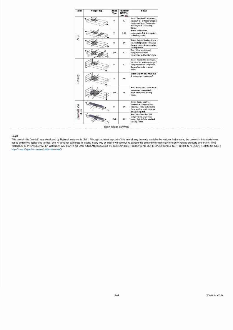
The two primary criteria for selecting the right type of strain gauge are sensitivity and precision. In general, if you use more strain gauges, (a full-bridge circuit rather than a quarter-bridge) your
measurement will respond more quickly and be more precise. On the other hand, cost will also play a large part in determining the type of strain gauge you select. Typically, full-bridge strain gaug
are significantly more expensive than half-bridge and quarter-bridge gauges. For a summary of the various types of strain and strain gauges, please refer to the Strain Gauge Summary table below
7/27/2019 Aplikacija mjernih traka.pdf
http://slidepdf.com/reader/full/aplikacija-mjernih-trakapdf 4/44/4 www.ni.c
Strain Gauge Summary
Legal
This tutorial (this "tutorial") was developed by National Instruments ("NI"). Although technical support of this tutorial may be made available by National Instruments, the content in this tutorial ma
not be completely tested and verified, and NI does not guarantee its quality in any way or that NI will continue to support this content with each new revision of related products and drivers. THIS
TUTORIAL IS PROVIDED "AS IS" WITHOUT WARRANTY OF ANY KIND AND SUBJECT TO CERTAIN RESTRICTIONS AS MORE SPECIFICALLY SET FORTH IN NI.COM'S TERMS OF US
).http://ni.com/legal/termsofuse/unitedstates/us/