Embed Size (px)
Citation preview

A R C H I V E S O F M E T A L L U R G Y A N D M A T E R I A L S
Volume 55 2010 Issue 3
M. HOJNY∗
APPLICATION OF AN INTEGRATED CAD/CAM/CAE/IBC SYSTEM IN THE STAMPING PROCESS OF A BATHTUB 1200 S
ZASTOSOWANIE ZINTEGROWANEGO SYSTEMU CAD/CAM/CAE/IBC W PROCESIE TŁOCZENIA WANNY 1200 S
Nowadays, metal stamping industries have been characterized by a strong demand for reduced development costsand time. Therefore, computer aided product development has become one of the most important techniques in the stamp-ing industry. In the paper, according to the concurrent engineering concept, an integrated CAD/CAM/CAE/IBC systemfor stamping die is implemented. This system includes, CAD/CAE software PRO/ENGINEER, stamping formabilityanalysis software DYNAFORM, structural analysis software DSA (Die Structural Analysis), CAM software and productdatabase. In order to allow three geographically dispersed teams to simultaneously work on the development of products,the Internet-Based Collaboration (IBC) system to shear design models and analysis results has been developed. TheCAD/CAM/CAE/IBC system can greatly reduce the development time and cost, improve the product quality, and pushproduct into the market in a relatively short time. This paper uses the development of a bathtub 1200 S as an exampleto show the possibility of the system, in which the different development stages can be performed simultaneously.
Keywords: CAD/CAM/CAE system, equivalent drawbead, deep drawing, bathtub, restraining force, concurrentengineering (CE)
W dzisiejszych czasach, przemysł tłoczniczy charakteryzuje się intensywnym poszukiwaniem sposobów na zwięk-szenie wydajności przy równoczesnym skróceniu czasu rozwoju produktu oraz kosztów. Dlatego też, komputerowe wspo-maganie rozwoju produktu stało się jedną z najbardziej istotnych technik w przemyśle tłoczniczym. W prezentowanejpracy, zgodnie z koncepcją inżynierii współbieżnej zaimplementowano zintegrowany system CAD/CAM/CAD/CAE/IBCwspomagający projektowanie narzędzi tłoczniczych. Wspomniany system składa się, z oprogramowania CAD/CAEPRO/ENGINEER, oprogramowania do analiz procesów tłoczenia DYNAFORM, oprogramowania do analiz struktural-nych DSA (Die Structural Analysis), oprogramowania CAM i bazy danych. W celu umożliwienia trzem geograficznierozproszonym zespołom równoczesną pracę nad rozwojem produktu, opracowano internetowy system (IBC) umożliwia-jący współdzielenie modeli geometrycznych i wyników analiz. Zaimplementowany system CAD/CAM/CAE/IBC możeznacząco zredukować czas rozwoju i koszty, poprawić jakość produktu, i dzięki temu wprowadzić produkt na rynekw względnie krótkim czasie. W prezentowanym artykule rozwój wanny 1200 S posłużył jako przykład pokazującymożliwości systemu, w którym różne etapy rozwoju mogą być wykonane równolegle.
1. Introduction
Collaborative design is a new concept for shar-ing design information and knowledge in various di-visions in order to improve product quality and to re-duce design time. In a collaborative system, design-ers and engineers can share their work with globallydistributed colleagues via the networks. Huang at al.[1] developed a web based framework for concur-rent product development. The framework integrat-ed the concept of agents into workflow management.Frank et al. [2] constructed a data oriented concur-rent engineering framework synchronizing the statusof data. System offers customizable group manage-ment and the collaboration approach is character-ized by the coordination of synchronous work on
a common information space. Tang [3] constructeda collaborative design environment to facilitate ac-tive die maker involvement in metal stamping prod-uct development. The author takes the view thatdie maker should be involved in new product de-velopment processes as early as possible to enableconcurrent engineering practice in metal stampingdevelopment.
Moreover, an integrated CAD/CAM/CAE sys-tem can tremendously improve productivity. Lin [4]took advantage of the concurrent engineering con-cept and developed an integrated CAD/CAM/CAEsystem for designing stamping dies of mobile phone.In most cases, the stamping product design is alwaysseparated from the die and process design, with thelatter two being carried out by skillful die and tool
∗ AGH UNIVERSITY OF SCIENCE AND TECHNOLOGY, 30-059 KRAKÓW, 30 MICKIEWICZA AV., POLAND

714
makers using and experience-based and trial and er-ror procedure. The stamping product and die de-velopment activities have been performed separate-
ly and sequentially by designers and engineers, asshown in Figure 1.
Fig. 1. A traditional process of part development (sequential engineering)
In recent years, the concept of concurrent en-gineering (CE) has been proposed to overcome theproblems of the sequential design approach. In thepractice of concurrent engineering, product, processand all life cycle issues are considered and reviewedthroughout all phases of the development cycle. Aconcurrent methods for developing new productswould depend strongly on how CAD/CAM/CAEsystem is applied to the design and analysis of theprocess, the tools and the part. Process using a in-
tegrated CAD/CAM/CAE approach with FEM sim-ulation is shown in Figure 2. The data flow of de-veloping a sheet metal part with FEM simulation isshown in Figure 3. With the help of FEM simulation,amendment of the preliminary or final design of theproduct die after the tool try-out can be avoided.Others forming parameters, which would result in aproduct with the required quality, can be determinedin an efficient way [5].
Fig. 2. A product development process with CAD/CAM/CAE system support
Fig. 3. The data flow in concurrent product development

715
This paper presents an integratedCAD/CAM/CAE/IBC system for redesigning stamp-ing die of a bathtub 1200 S using concurrent engi-neering (CE). The redesign and verification of diefor the stamping of bathtub 1200 was performedusing finite element method. The major and minorstrain distributions obtained from the finite elementsimulations were used in conjunction with the form-ing limit diagram to predict the onset of fracture.The first set of die was performed without supportof CAE/IBC system. The difficulty encountered inthe real stamping process is the occurrence of bothfracture and wrinkling, as shown in Figure 4.
Fig. 4. The split and wrinkles localization after stamping processof bathtub 1200 S
The stamped bathtub is made of DC06 gradesteel and is to be formed by a single drawing processto avoid drawing marks caused by a multi stampingprocess. Also, both the flange width around the cav-ity and maximum thinning of the final shape should
be greater than 70 mm and lower than ±40%, re-spectively, required by the part design. The effortsfocused on the die design for the stamping of a bath-tub are mainly to avoid major defects such as wrin-kling and fracture. A successful die design generallyresults from an accurate prediction of the metal flowduring the forming process, and on the other handon the experience and know-how of engineers inactual practice.
2. The integrated CAD/CAM/CAE/IBC system
The general scheme of the integratedCAD/CAM/CAE/IBC system for stamping dies ispresented in Figure 5. This system includes a setof CAD die face design software, a set of stampingformability analyzing software, CAM software andproduct database. In this paper, an Internet-BasedCollaboration (IBC) system has been developed tosupport and share design models and analysis resultsbetween geographically dispersed users. The systeminfrastructure and its mechanism are built basedon some JAVA/PHP, Web technologies and TomcatWeb server. This system consists of two primarymodules:– a resource sharing module: FEM analysis results,– a Web-based visualization module to support prod-uct preview of design parts.In order to manipulate interactive 3D models ef-fectively in the Web, some concise 3D formats forWeb application such as VRML,X3D and MPEG,have been launched to represent the geometry of 3DCAD models. Most of the newest CAD systems areequipped with an export function to convert a nativemodel to a concise 3D model for Web application(e.g. X3D or VRML).
Fig. 5. The scheme of the integrated CAD/CAM/CAE/IBC system of stamping part

716
By using PRO/ENGINEER, DYNAFORM,DSA,IBC system and various product databases, an inte-grated CAD/CAM/CAE/IBC system was developed.Since the entire development process shares thesame 3D model, the various process of developingdie can be performed simultaneously, which cangreatly reduce the development time.
3. The application of an integratedCAD/CAM/CAE/IBC system
3.1. Drawing and trimming die design
Die face design is very important in the ini-tial design stage. Die face design involves importingbathtub surface into DYNAFORM software usingIGES format files, then the die face can be developedbased on stamping design knowledge. FEM modelof a die were prepared by using DFE (Die FaceEngineering) module of DYNAFORM software.
By integrating with forming simulation, DFEhelps to reduce iteration time for tooling design inthe CAD system. Die face design includes adden-dum design, binder face design and drawbead de-sign, as shown in Figure 6. Addendum is designedto assists forming and improve formability. Binderface is used to hold blank to avoid wrinkle beforefeeding into drawing cavities. Drawbeads are used tocontrol blank to be evenly fed into drawing cavitiesto avoid any defects through changing its locations,lengths and cross section. Die used in this paperinclude drawing dies and trimming dies. A 3D solidmodel, which is identical to real product, is used indie design to avoid any interference and to facili-tate design and modification, which fundamentallyreduces the design time. Figure 7 shows a 3D soliddesign model of the drawing die. Drawing dies areused to shape the part. In order to obtain the desiredshape, we need very strong forming force, whichmakes it necessary to evaluate its structural stresses.The structure of drawing dies includes e.g. drawingpunch and cavity, guiding plane, blank positioningunit for upper and lower die set and blank holder.The assembly of the standard parts for drawing diesinclude e.g. screws, guide plates.
Fig. 6. Die face of a bathtub 1200 S
Fig. 7. 3D solid model of drawing die
Trimming dies are used to cut blanks. Sincescraps will not be removed automatically, we needto add additional scrap cutters where necessary.Using analytical module (SSR – Scrap Sheddingand Removal Analysis) built in DYNAFORM andLS-DYNA solver, we can analyze all trim processbefore completing die design to avoid extendeddown time due to scrap shedding and removal relat-ed issues.
3.2. Formability analysis vs. industrial dietry-out
Blank material is DC06EK. Forming parame-ters and material properties need to be specified,which include thickness (1.5 mm), yield strength(144 MPa), hardening exp. n-value (0.243), andanisotropy r-value (2.19). The other process parame-ters, such as the friction coefficient and blank holderpressure, was set differently for the different stamp-ing conditions. The strain distribution for variousstamping conditions were established for designingan optimum set of stamping dies. The die designobtained from the finite element analysis was vali-dated by the production part. The final part geome-tries generated by a PRO/ENGINEER system for the
717
initial die design were provided by the CAD engi-neer. In the finite element simulation, the tooling isconsidered to be rigid. The contact conditions’ pro-ceeding during stamping of bathtub was identifiedby algorithms coded in DYNAFORM system. In thepresent work, the four node shell element was usedto construct the meshes. An optimum sheet blankshape determined by the finite element analysis wasused for all die designs by using BSE (Blank SizeEstimated) module of DYNAFORM software. Thefour corners of this optimum sheet blank were cut offto facilitate metal flow at the edges. The shape of diecavity confirming to the geometry of the bathtub wasalso maintained, as for all of the die face designs,since the bathtub was drawn to the desired shape inone operation. In consequence, the die design wasfocused only on the die face. In order to analyzethe metal flow, a flat surface without a drawbeadwas used as the initial design for the die face. Theanalysis of the modified die design was performedaccording to the pattern of metal flow obtained fromthe finite element simulations. In addition to the dieface design, computer simulations were also con-ducted to study the effect of the process parameterssuch as friction- and blank holder pressure, on theformability of the bathtub stamping process.
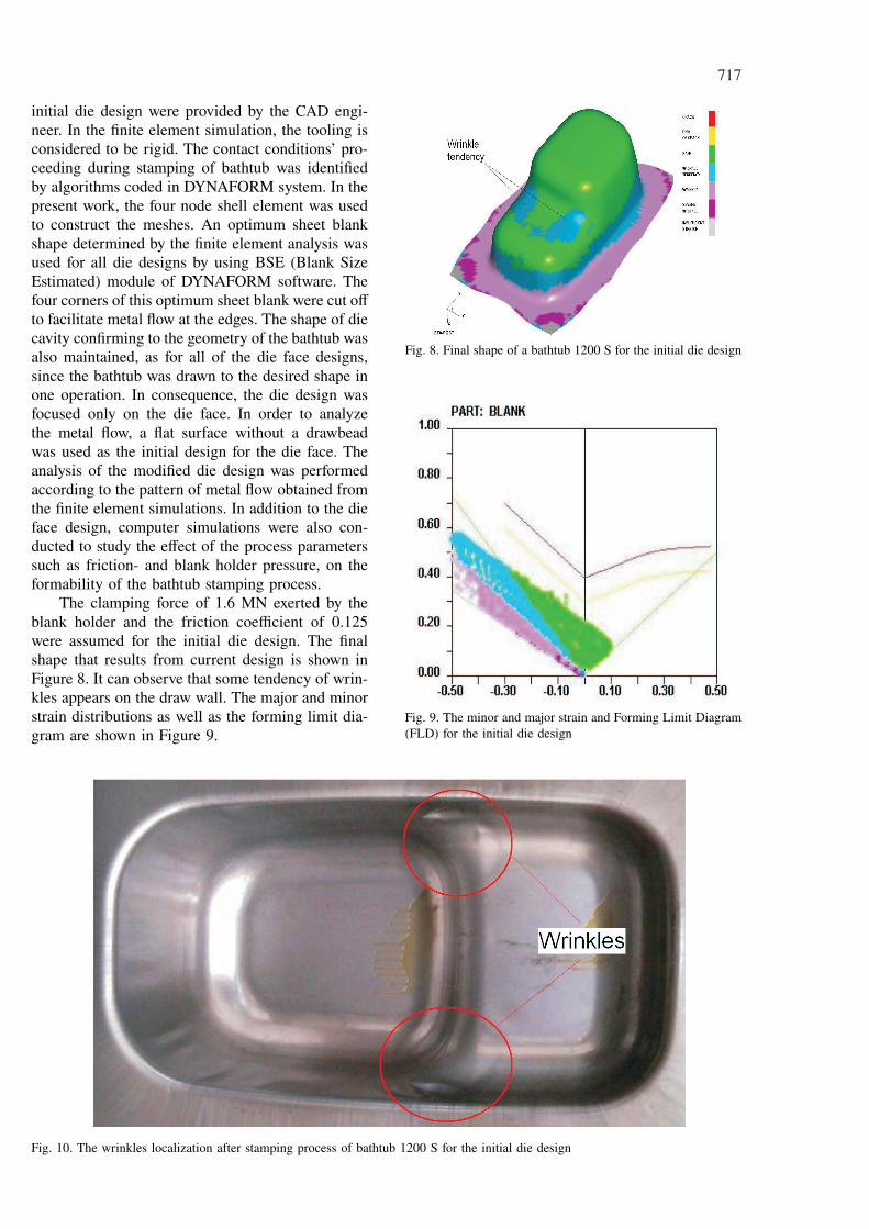
The clamping force of 1.6 MN exerted by theblank holder and the friction coefficient of 0.125were assumed for the initial die design. The finalshape that results from current design is shown inFigure 8. It can observe that some tendency of wrin-kles appears on the draw wall. The major and minorstrain distributions as well as the forming limit dia-gram are shown in Figure 9.
Fig. 8. Final shape of a bathtub 1200 S for the initial die design
Fig. 9. The minor and major strain and Forming Limit Diagram(FLD) for the initial die design
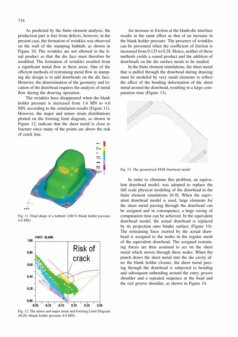
Fig. 10. The wrinkles localization after stamping process of bathtub 1200 S for the initial die design
718
As predicted by the finite element analysis, theproduction part is free from defects, however, in thepresent case, the formation of wrinkles was observedon the wall of the stamping bathtub, as shown inFigure 10. The wrinkles are not allowed in the fi-nal product so that the die face must therefore bemodified. The formation of wrinkles resulted froma significant metal flow at these areas. One of theefficient methods of restraining metal flow in stamp-ing die design is to add drawbeads on the die face.However, the determination of the geometry and lo-cation of the drawbead requires the analysis of metalflow during the drawing operation.
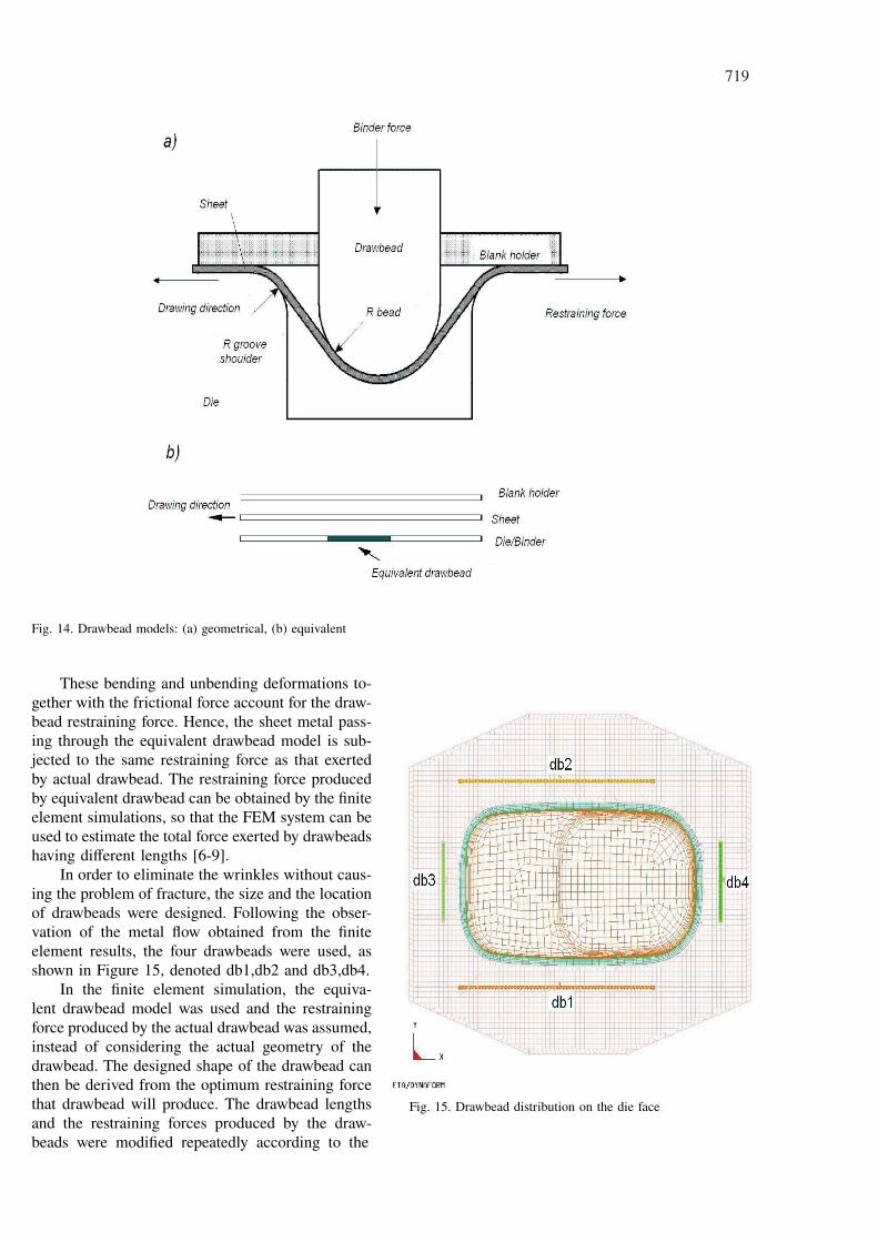
The wrinkles have disappeared when the blankholder pressure is increased from 1.6 MN to 4.0MN, according to the simulation results (Figure 11).However, the major and minor strain distributionsplotted on the forming limit diagram, as shown inFigure 12, indicate that the sheet metal is close tofracture since many of the points are above the riskof crack line.
Fig. 11. Final shape of a bathtub 1200 S (blank holder pressure4.0 MN)
Fig. 12. The minor and major strain and Forming Limit Diagram(FLD) (blank holder pressure 4.0 MN)
An increase in friction at the blank-die interfaceresults in the same effect as that of an increase inthe blank holder pressure. The presence of wrinklescan be prevented when the coefficient of friction isincreased from 0.125 to 0.28. Hence, neither of thesemethods yields a sound product and the addition ofdrawbeads on the die surface needs to be studied.
In the finite element simulations, the sheet metalthat is pulled through the drawbead during drawingmust be modeled by very small elements to reflectthe effect of the bending deformation of the sheetmetal around the drawbead, resulting in a large com-putation time (Figure 13).
Fig. 13. The geometrical FEM drawbead model
In order to eliminate this problem, an equiva-lent drawbead model, was adopted to replace thefull scale physical modeling of the drawbead in thefinite element simulations [6-9]. When the equiv-alent drawbead model is used, large elements forthe sheet metal passing through the drawbead canbe assigned and in consequence, a huge saving ofcomputation time can be achieved. In the equivalentdrawbead model, the actual drawbead is replacedby its projection onto binder surface (Figure 14).The restraining force exerted by the actual draw-bead is assigned to the nodes in the regular meshof the equivalent drawbead. The assigned restrain-ing forces are then assumed to act on the sheetmetal which moves through these nodes. When thepunch draws the sheet metal into the die cavity af-ter the blank holder closure, the sheet metal pass-ing through the drawbead is subjected to bendingand subsequent unbending around the entry grooveshoulder and a repeated sequence at the bead andthe exit groove shoulder, as shown in Figure 14.
719
Fig. 14. Drawbead models: (a) geometrical, (b) equivalent
These bending and unbending deformations to-gether with the frictional force account for the draw-bead restraining force. Hence, the sheet metal pass-ing through the equivalent drawbead model is sub-jected to the same restraining force as that exertedby actual drawbead. The restraining force producedby equivalent drawbead can be obtained by the finiteelement simulations, so that the FEM system can beused to estimate the total force exerted by drawbeadshaving different lengths [6-9].
In order to eliminate the wrinkles without caus-ing the problem of fracture, the size and the locationof drawbeads were designed. Following the obser-vation of the metal flow obtained from the finiteelement results, the four drawbeads were used, asshown in Figure 15, denoted db1,db2 and db3,db4.
In the finite element simulation, the equiva-lent drawbead model was used and the restrainingforce produced by the actual drawbead was assumed,instead of considering the actual geometry of thedrawbead. The designed shape of the drawbead canthen be derived from the optimum restraining forcethat drawbead will produce. The drawbead lengthsand the restraining forces produced by the draw-beads were modified repeatedly according to the
Fig. 15. Drawbead distribution on the die face

720
analysis of metal flow obtained from the finite el-ement simulations until an optimum combinationwas achieved. The determined lengths for db1,db2and db3,db4 are 900 mm and 300 mm, respectively.The restraining forces for all drawbeads are 95.140N/mm. The restraining force produced by the draw-bead is a function of the material properties of thesheet metal, the shape of the drawbead and the fric-tion at the interface between the bead and the sheetmetal [6-9]. The typical drawbead, in which thedrawbead shape can be characterized by the radiusof the bead (or the groove shoulder), as shown inFigure 16, was adopted.
The relationship between the geometry of thedrawbead and the corresponding restraining forcewas established by the finite element simulations.The approximate drawbead radius for the corre-sponding restraining force was confirmed by thecomputer simulation. The drawbead radius (R1=R2)for the restraining forces of 95.140 N/mm, obtainedfrom finite element simulations, is 6 mm. The exitand entrance radius (R3 = R4) of drawbead groove,is 24 mm. The drawbead width and height (W1 andH1) are 12 mm and 15 mm, respectively. The clear-ance of drawbead groove is 0.1 mm. The shape ob-tained from the finite element simulation with theuse of the optimum drawbead geometry is shownin Figure 18, from which it is seen clearly that the
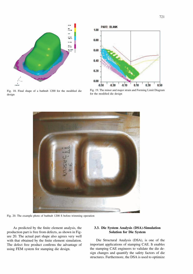
tendency of wrinkles disappear and that the calculat-ed flange width is greater than 70 mm (Figure 17).Thinning distributions results in – 12% and 27%, re-spectively. The thinning distributions range of 40%was contained. As for the major and minor strainscomputed from the computer simulation, as shownin Figure 19, the corresponding points are all belowthe risk of crack line. This indicates that a defectfree part can be produced under the stamping condi-tions, such as the sheet blank shape, the blank holderpressure, the coefficient of friction and the drawbeadlocations, obtained from the finite element analysis.
Fig. 16. Hemicycle drawbead profile
Fig. 17. Thinning distribution for the final part
721
Fig. 18. Final shape of a bathtub 1200 for the modified diedesign
Fig. 19. The minor and major strain and Forming Limit Diagramfor the modified die design
Fig. 20. The example photo of bathtub 1200 S before trimming operation
As predicted by the finite element analysis, theproduction part is free from defects, as shown in Fig-ure 20. The actual part shape also agrees very wellwith that obtained by the finite element simulation.The defect free product confirms the advantage ofusing FEM system for stamping die design.
3.3. Die System Analysis (DSA)-SimulationSolution for Die System
Die Structural Analysis (DSA), is one of theimportant applications of stamping CAE. It enablesthe stamping CAE engineers to validate the die de-sign changes and quantify the safety factors of diestructures. Furthermore, the DSA is used to optimize

722
Fig. 21. Equivalent stress distribution for the low ring of the drawing die
the die design for weight reduction, hence provid-ing opportunity for cost savings. The DSA is alsoutilized to identify root cause of die breakage dur-ing the tryout and stamping production. The ben-efits of DSA have provided significant values tothe stamping manufacturers in terms of die con-struction and stamping operations. DSA Consists ofthree Sub-Systems: Die Structure Integrity (DSI),Scrap Shedding and Removal (SSR) and Sheet Met-al Transfer and Handling (SMTH). The die structureshall have sufficient strength, and no interferenceis allowed among the various components. Afterthe solid models have been developed (Figure 7),designers use the PRO/ENGINEER digital mockupmodule to perform motion and interference analysison the models. After performing this analysis, anypotential interference can be avoided and identified.In addition, since the stamping force is very large,it is necessary to perform a structural analysis onthe models. In structural analysis, engineers applyforming forces obtained from the formability analy-sis and the die’s boundary conditions to determinethe stress. Figure 21 presents the stress distributionfor the low ring of the drawing die. The evaluationcriterion of the structure analysis is that the stressof the die must be less than yield strength of the diematerial divided by the safety factor.
4. Conclusion
This paper presents an integratedCAD/CAM/CAE system for stamping die devel-opment of a bathtub 1200 S using a concurrentengineering approach. In order to allow three geo-graphically dispersed teams to simultaneously work
on the development of products, the Internet-BasedCollaboration (IBC) system has been developed. TheIBC system enables users to share design models,analysis results and can notify design modificationto users when it is required. Engineers can ex-change information about common design matersby the conferencing function of the system and theannotation function. Using presented an integratedCAD/CAM/CAE/IBC system, the die face designfor stamping of a bathtub 1200 S was investigated.In the investigation, the cause of the formation ofwrinkles was studied on the basis of the metal flowobtained from the simulation results. The forminglimit diagram was also used in conjunction with thefinite element results to predict the occurrence offracture. In addition, an equivalent drawbead modelwas applied to the finite simulation to save compu-tation time. With the use of equivalent drawbeads,the actual drawbead shapes are not considered un-til the optimum restraining force and die design isachieved, resulting in an efficient approach for draw-bead application. At the end the industrial die verifi-cation has been done, where the defect free producthas been obtained. With the aid of FEM simulation,forming problems can be visually identified and dietryout has been shortened into several days.
REFERENCES
[1] G. H u a n g, J. H u a n g, K. M a k, Agent-basedworkflow management in collaborative product de-velopment, Computer Aided Design 32, 133 (2000).
[2] A. F r a n k, J. S e l l e n t i n, B. M i t s c h a n g,TOGA a customizable service for data centric col-laboration, Information Systems 25, 157 (2000).

723
[3] D. T a n g, An agent-based collaborative designsystem to facilitate active die-maker involvementin stamping part design, Computers in Industry 54,253 (2004).
[4] B.T. L i n, Application of an integratedRE/RP/CAD/CAE/CAM system for magnesiumalloy shell of mobile phone, Journal of MaterialsProcessing Technology 209, 2018 (2009).
[5] A. P i e l a, J. R o j e k, Validation of the resultsof numerical simulation of deep drawing of tai-lor welded blanks, Archives of Metallurgy 48, 37(2003).
[6] F.K. C h e n, P.C. T s z e n g, An analysis of draw-bead restraining force in the stamping process, In-
ternational Journal of Machine Tools and Manufac-ture 38, 827 (1998).
[7] S. L i, Z. L i n, W. X u, Y. B a o, An im-proved equivalent drawbead model and its appli-cation, Journal of Materials Processing Technology121, 308 (2002).
[8] M. S a m u e l, Influence of drawbead geometry onsheet metal forming, Journal of Materials Process-ing Technology 122, 94 (2002).
[9] H. N a c e u r, Y.Q. G u o, J.L. B a t o z, C.K n o p f - L e n o i r, Optimization of drawbead re-straining forces and drawbead design in sheet metalforming process, International Journal of Mechani-cal Sciences 43, 2407 (2001).
Received: 10 February 2010.