Embed Size (px)
Citation preview
Copyright 2016 Shell Exploration and Production Company
WELLBORES & VERTICAL REFERENCE LEVELS
Bert Kampes Team Lead Geodesy
APSG 35 Spring Meeting
Houston, April 29, 2016

Copyright 2016 Shell Exploration and Production Company
DEFINITIONS & CAUTIONARY NOTE
Reserves: Our use of the term “reserves” in this presentation means SEC proved oil and gas reserves.
Resources: Our use of the term “resources” in this presentation includes quantities of oil and gas not yet classified as SEC proved oil and gas reserves. Resources are consistent with the Society of Petroleum Engineers 2P and 2C definitions.
Organic: Our use of the term Organic includes SEC proved oil and gas reserves excluding changes resulting from acquisitions, divestments and year-average pricing impact.
Shales: Our use of the term ‘shales’ refers to tight, shale and coal bed methane oil and gas acreage.
The companies in which Royal Dutch Shell plc directly and indirectly owns investments are separate entities. In this document “Shell”, “Shell group” and “Royal Dutch Shell” are sometimes used for convenience where references are made to Royal Dutch Shell plc and its subsidiaries in general. Likewise, the words “we”, “us” and “our” are also used to refer to subsidiaries in general or to those who work for them. These expressions are also used where no useful purpose is served by identifying the particular company or companies. ‘‘Subsidiaries’’, “Shell subsidiaries” and “Shell companies” as used in this document refer to companies over which Royal Dutch Shell plc either directly or indirectly has control. Companies over which Shell has joint control are generally referred to as “joint ventures” and companies over which Shell has significant influence but neither control nor joint control are referred to as “associates”. The term “Shell interest” is used for convenience to indicate the direct and/or indirect ownership interest held by Shell in a venture, partnership or company, after exclusion of all third-party interest.
This presentation contains forward-looking statements concerning the financial condition, results of operations and businesses of Royal Dutch Shell. All statements other than statements of historical fact are, or may be deemed to be, forward-looking statements. Forward-looking statements are statements of future expectations that are based on management’s current expectations and assumptions and involve known and unknown risks and uncertainties that could cause actual results, performance or events to differ materially from those expressed or implied in these statements. Forward-looking statements include, among other things, statements concerning the potential exposure of Royal Dutch Shell to market risks and statements expressing management’s expectations, beliefs, estimates, forecasts, projections and assumptions. These forward-looking statements are identified by their use of terms and phrases such as ‘‘anticipate’’, ‘‘believe’’, ‘‘could’’, ‘‘estimate’’, ‘‘expect’’, ‘‘intend’’, ‘‘may’’, ‘‘plan’’, ‘‘objectives’’, ‘‘outlook’’, ‘‘probably’’, ‘‘project’’, ‘‘will’’, ‘‘seek’’, ‘‘target’’, ‘‘risks’’, ‘‘goals’’, ‘‘should’’ and similar terms and phrases. There are a number of factors that could affect the future operations of Royal Dutch Shell and could cause those results to differ materially from those expressed in the forward-looking statements included in this presentation, including (without limitation): (a) price fluctuations in crude oil and natural gas; (b) changes in demand for Shell’s products; (c) currency fluctuations; (d) drilling and production results; (e) reserves estimates; (f) loss of market share and industry competition; (g) environmental and physical risks; (h) risks associated with the identification of suitable potential acquisition properties and targets, and successful negotiation and completion of such transactions; (i) the risk of doing business in developing countries and countries subject to international sanctions; (j) legislative, fiscal and regulatory developments including potential litigation and regulatory measures as a result of climate changes; (k) economic and financial market conditions in various countries and regions; (l) political risks, including the risks of expropriation and renegotiation of the terms of contracts with governmental entities, delays or advancements in the approval of projects and delays in the reimbursement for shared costs; and (m) changes in trading conditions. All forward-looking statements contained in this presentation are expressly qualified in their entirety by the cautionary statements contained or referred to in this section. Readers should not place undue reliance on forward-looking statements. Additional factors that may affect future results are contained in Royal Dutch Shell’s 20-F for the year ended 31 December, 2015 (available at www.shell.com/investor and www.sec.gov ). These factors also should be considered by the reader. Each forward-looking statement speaks only as of the date of this presentation, 4/29/2016. Neither Royal Dutch Shell nor any of its subsidiaries undertake any obligation to publicly update or revise any forward-looking statement as a result of new information, future events or other information. In light of these risks, results could differ materially from those stated, implied or inferred from the forward-looking statements contained in this presentation. There can be no assurance that dividend payments will match or exceed those set out in this presentation in the future, or that they will be made at all.
We use certain terms in this presentation, such as discovery potential, that the United States Securities and Exchange Commission (SEC) guidelines strictly prohibit us from including in filings with the SEC. U.S. Investors are urged to consider closely the disclosure in our Form 20-F, File No 1-32575, available on the SEC website www.sec.gov. You can also obtain this form from the SEC by calling 1-800-SEC-0330.
March 2016 2
Copyright 2016 Shell Exploration and Production Company
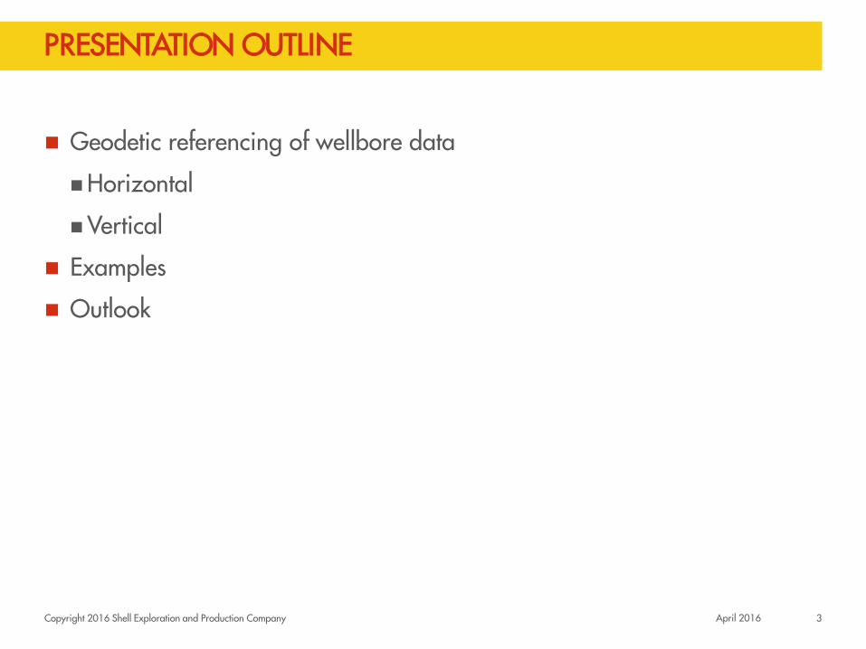
PRESENTATION OUTLINE
Geodetic referencing of wellbore data
Horizontal
Vertical
Examples
Outlook
3 April 2016

Copyright 2016 Shell Exploration and Production Company
WELLBORE SURVEYING PRINCIPLES
Geodetic principles:
Coordinate Reference System (CRS):
Structured metadata containing geodetic referencing information
No CRS: coordinates are ambiguous or uninterpretable
CRS types: Geographic (Lat, Lon), Projected (E, N), Engineering (local X, local Y)
Wellbore Survey Observables: How is position measured? Azimuth
Inclination
Measured depth
No CRS required: no coordinates, but measurements!
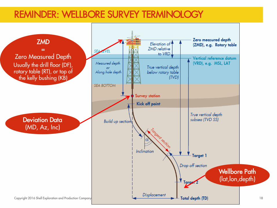
Observation reference is required (what constitutes zero)
4 April 2016
Relative to Magnetic, True, or Grid
Always relative to vertical
From ZMD (Zero Measured Depth), positive down

Copyright 2016 Shell Exploration and Production Company
WELLBORE DIRECTIONAL SURVEY DEVIATION DATA
Azimuth Measured Depth
5 April 2016
Inclination
MD AZ INC

OBSERVATIONS: MD, AZ, INC
Survey measurement are made at discrete “survey stations”
3D shape of well path is thus determined incrementally
Profile View MD AZ INC
0 0 0
100 0 0
200 25 20
300 45 40
400 70 60
500 90 80
depth
Plan View
True North
East
300 400 500
KB
100
100
200 200
300
400
500
Picture assumes Azimuth is relative to True North. Alternatives: Magnetic North requires magnetic declination Grid North requires Projected CRS Measured Depth units are also needed!
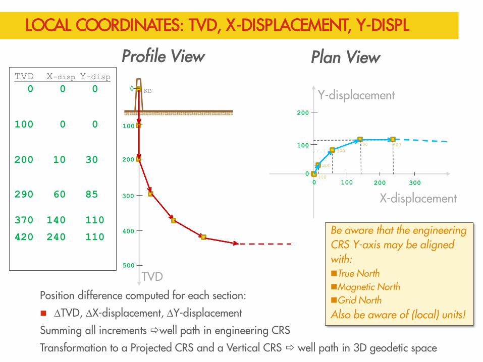
LOCAL COORDINATES: TVD, X-DISPLACEMENT, Y-DISPL
Position difference computed for each section:
DTVD, DX-displacement, DY-displacement
Summing all increments well path in engineering CRS
Transformation to a Projected CRS and a Vertical CRS well path in 3D geodetic space
Profile View TVD X-disp Y-disp
0 0 0
100 0 0
200 10 30
290 60 85
370 140 110
420 240 110
TVD
Plan View
Y-displacement
X-displacement
400 500
KB
100
100
300
400
100
100
200
200 200
300
200 300
500
0
0 0
Be aware that the engineering CRS Y-axis may be aligned with: True North Magnetic North Grid North Also be aware of (local) units!
Copyright 2016 Shell Exploration and Production Company
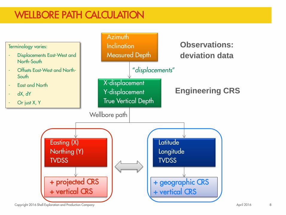
WELLBORE PATH CALCULATION
Azimuth Inclination Measured Depth
Observations:
deviation data
Easting (X) Northing (Y) TVDSS
+ projected CRS + vertical CRS
Wellbore path
X-displacement Y-displacement True Vertical Depth
Engineering CRS
“displacements”
Latitude Longitude TVDSS
+ geographic CRS + vertical CRS
Terminology varies:
- Displacements East-West and North-South
- Offsets East-West and North-South
- East and North
- dX, dY
- Or just X, Y
April 2016 8

Copyright 2016 Shell Exploration and Production Company
TYPICAL WELLBORE SURVEY REPORT
April 2016 9

Copyright 2016 Shell Exploration and Production Company
THE ENGINEERING (LOCAL) CRS
3 orthogonal axes:
X-displacement
Y-displacement
TVD
TVD
Well Reference Point (0, 0, 0)
April 2016 10

Copyright 2016 Shell Exploration and Production Company
THE PROJECTED CRS (“REAL WORLD” CRS)
3 orthogonal axes:
Easting (X) – axis (or Longitude)
Northing (Y) – axis (or Latitude)
Depth (relative to a geodetic vertical reference)
dept
h
Well Reference Point (E, N, H) WRP
Grid North
This assumes Azimuth = Grid
April 2016 11

Copyright 2016 Shell Exploration and Production Company
THE VERTICAL CRS (DEPTH)
3 orthogonal axes:
Easting - axis
Northing - axis
Depth (below geodetic vertical reference)
Dep
th
Well Reference Point (EWRP, NWRP, HWRP) + projected CRS + vertical CRS
Grid North
Offset height to drill floor: dH
Ground Level Elevation: HTERRAIN
Vertical CRS is needed to qualify geodetic heights and depths
Height Well Reference Point: HWRP = HTERRAIN + dH Depth = TVD - HWRP
April 2016 12
Copyright 2016 Shell Exploration and Production Company
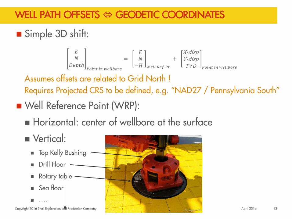
WELL PATH OFFSETS GEODETIC COORDINATES
Simple 3D shift:
𝐸𝑁
𝐷𝑒𝑝𝑡ℎ𝑃𝑜𝑖𝑛𝑡 𝑖𝑛 𝑤𝑒𝑙𝑙𝑏𝑜𝑟𝑒
= 𝐸 𝑁 −𝐻 𝑊𝑒𝑙𝑙 𝑅𝑒𝑓 𝑃𝑡
+ X-disp Y-disp
𝑇𝑉𝐷 𝑃𝑜𝑖𝑛𝑡 𝑖𝑛 𝑤𝑒𝑙𝑙𝑏𝑜𝑟𝑒
Assumes offsets are related to Grid North ! Requires Projected CRS to be defined, e.g. “NAD27 / Pennsylvania South”
Well Reference Point (WRP):
Horizontal: center of wellbore at the surface
Vertical: Top Kelly Bushing
Drill Floor
Rotary table
Sea floor
…. April 2016 13

RECAP OF WELL PATH
Well path depth levels
Coordinates: 1. True Vertical Depth (TVD) 2. X-displacement 3. Y-displacement
Units of measure: 1. Metres 2. (International) Feet This local 3D CRS needs to be related to: 1. a Geographic CRS or a Projected CRS 2. a Vertical CRS This requires coordinate transformations! True Vertical Depth varies in definition: TVD = Depth in Vertical CRS TVD = Depth below Well Reference Point
(i.e. local) TVDSS = Depth relative to MSL (in USA)

Copyright 2016 Shell Exploration and Production Company
Re-referencing wellbore survey data
EXAMPLES 1.1
15 April 2016
Copyright 2016 Shell Exploration and Production Company
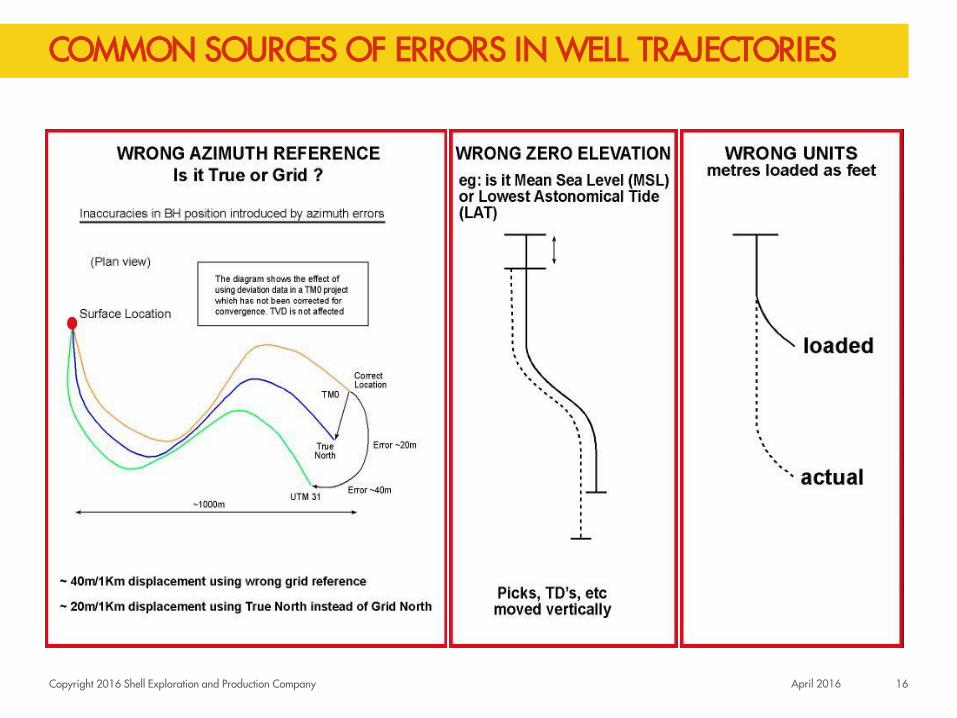
COMMON SOURCES OF ERRORS IN WELL TRAJECTORIES
April 2016 16
Copyright 2016 Shell Exploration and Production Company
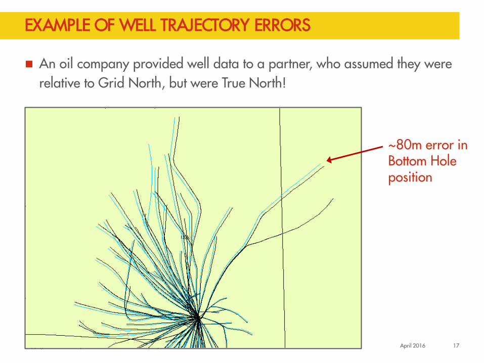
EXAMPLE OF WELL TRAJECTORY ERRORS
An oil company provided well data to a partner, who assumed they were relative to Grid North, but were True North!
~80m error in Bottom Hole position
April 2016 17
Copyright 2016 Shell Exploration and Production Company
REMINDER: WELLBORE SURVEY TERMINOLOGY
ZMD =
Zero Measured Depth
Usually the drill floor (DF), rotary table (RT), or top of
the kelly bushing (KB)
Wellbore Path (lat,lon,depth)
Deviation Data (MD, Az, Inc)
18

Copyright 2016 Shell Exploration and Production Company
RE-REFERENCING AFTER RE-SURVEY
1999: Drilling of top holes and some directional paths with offshore rig
KB = 82 ft (survey and logs)
Platform built, additional wellbores drilled
KB = 192 ft
2009: Re-survey of wellbores to reduce uncertainty (gyro)
19 April 2016

Copyright 2016 Shell Exploration and Production Company
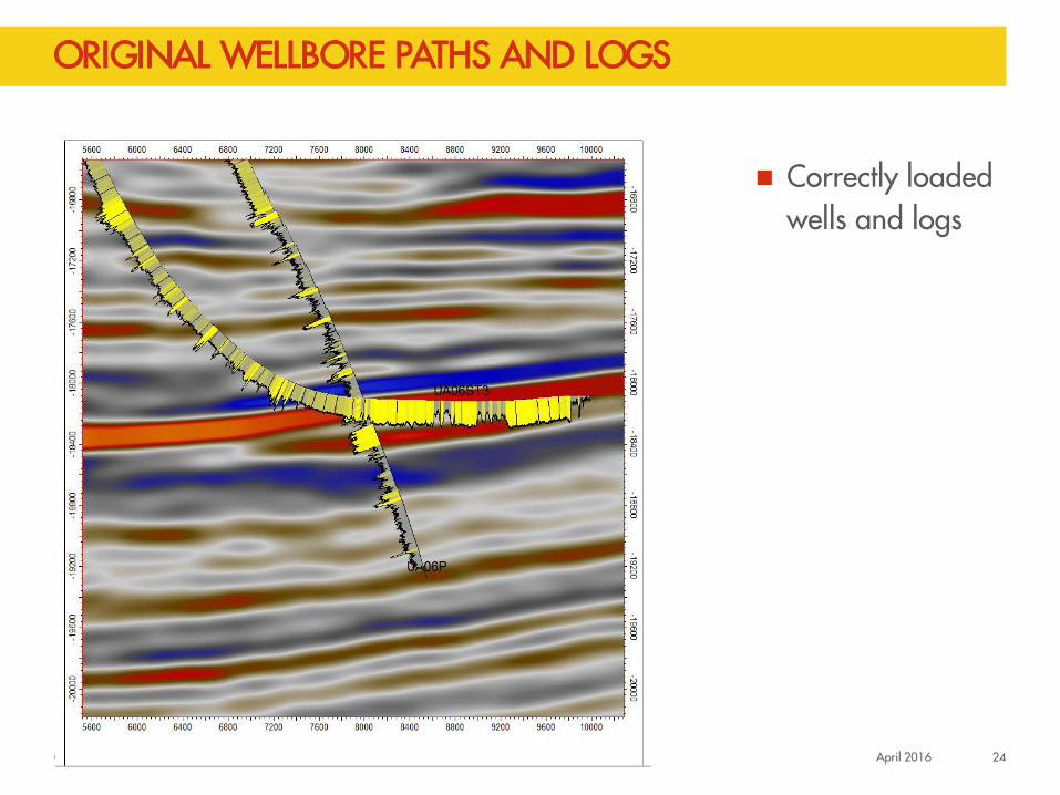
Correctly loaded wells and logs
ORIGINAL WELLBORE PATHS AND GAMMA RAY LOGS
April 2016 20

Copyright 2016 Shell Exploration and Production Company
Adjusted KB down: shifts whole trajectory including logs down
CHANGE OF KB IN SUBSURFACE APPLICATION
April 2016 21

Copyright 2016 Shell Exploration and Production Company
100
200
300
400
500
0 MD
KB=192
CHANGE OF WELLBORE SURVEY REFERENCE LEVEL
100
200
300
400
500
0
Wellbore KB changed
110
KB=82
April 2016 22
Copyright 2016 Shell Exploration and Production Company
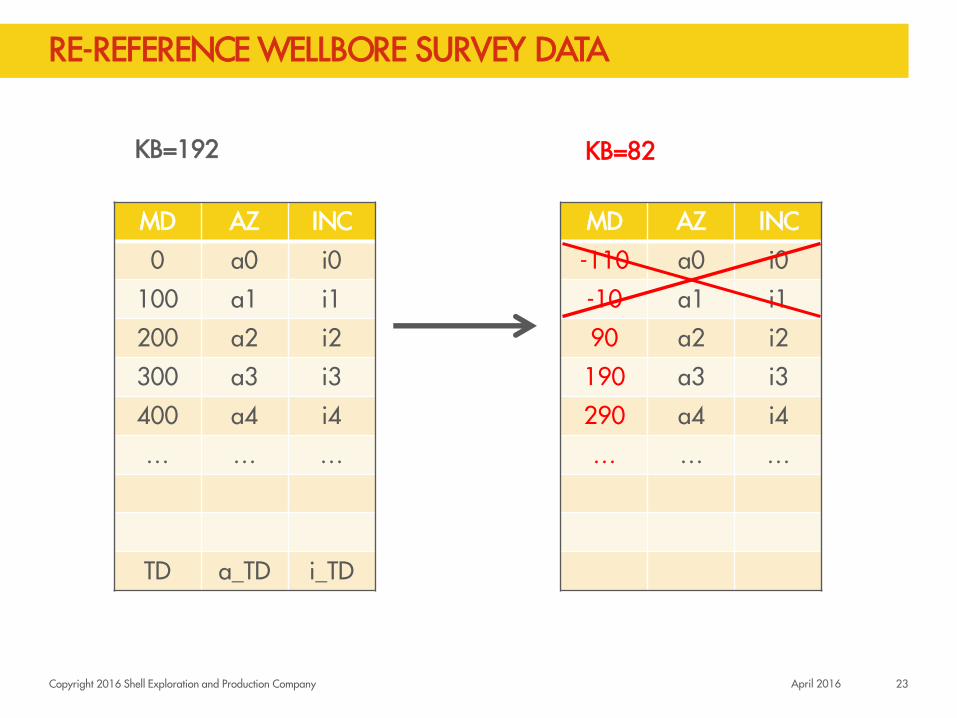
RE-REFERENCE WELLBORE SURVEY DATA
MD AZ INC
0 a0 i0
100 a1 i1
200 a2 i2
300 a3 i3
400 a4 i4
… … …
TD a_TD i_TD
23 April 2016
KB=192 KB=82
MD AZ INC
-110 a0 i0
-10 a1 i1
90 a2 i2
190 a3 i3
290 a4 i4
… … …
Copyright 2016 Shell Exploration and Production Company
Correctly loaded wells and logs
ORIGINAL WELLBORE PATHS AND LOGS
April 2016 24
Copyright 2016 Shell Exploration and Production Company
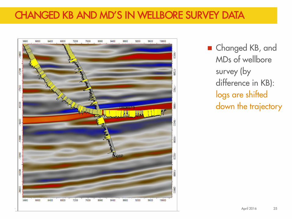
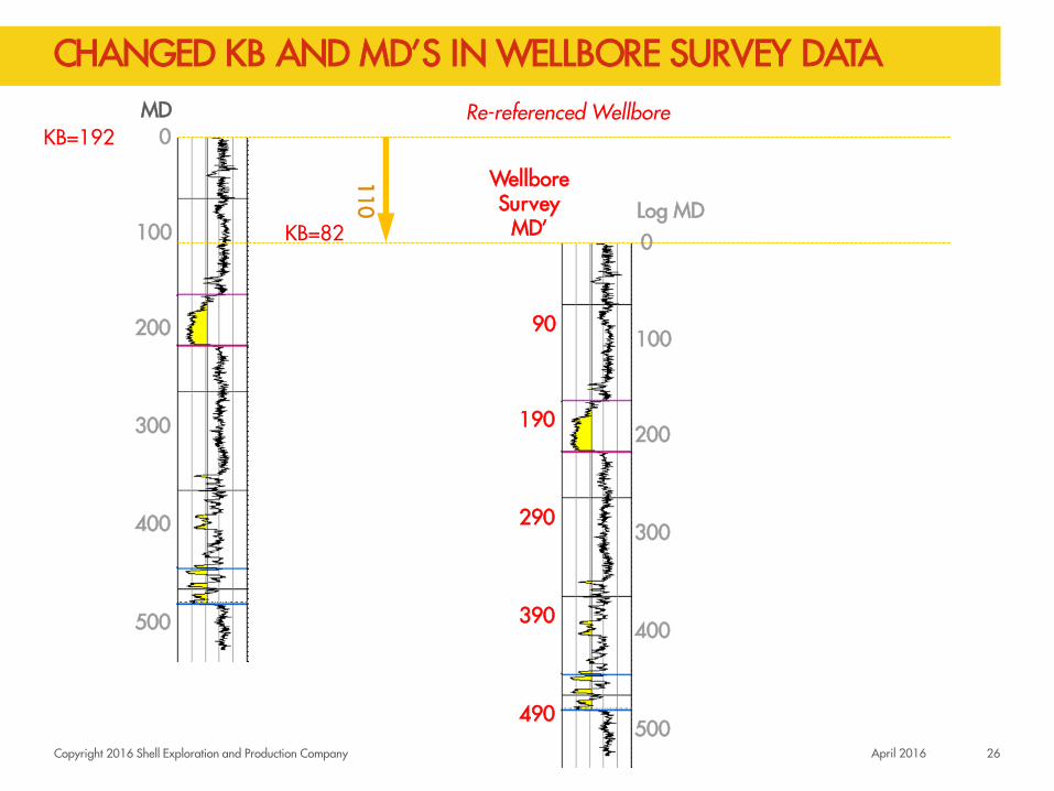
Changed KB, and MDs of wellbore survey (by difference in KB): logs are shifted down the trajectory
CHANGED KB AND MD’S IN WELLBORE SURVEY DATA
April 2016 25
Copyright 2016 Shell Exploration and Production Company
100
200
300
400
500
0 MD
KB=192
CHANGED KB AND MD’S IN WELLBORE SURVEY DATA
110
100
200
300
400
500
0 Log MD
Re-referenced Wellbore
90
190
290
390
490
Wellbore Survey
MD’ KB=82
April 2016 26

Copyright 2016 Shell Exploration and Production Company
100
200
300
400
500
0 MD
KB=192
CHANGED KB AND MD’S IN WELLBORE SURVEY DATA Wellbore KB & MD’s changed
110
90
190
290
390
490
100
200
300
400
500
0 Log MD
Wellbore Survey
MD’ KB=82
100
200
300
400
0 Log MD’
Re-referenced Log
90
190
290
390
April 2016 27

Copyright 2016 Shell Exploration and Production Company
RE-REFERENCING ISSUE SUMMARY
In driller database, all wellbores were re-referenced to platform KB = 192 ft (re-survey)
In subsurface application, wellbore survey data were loaded with KB = 82 ft; then, years later, changed to new KB = 192 ft
And quickly moved back to original KB when logs moved!
Re-referencing to be avoided (particularly in subsurface applications)
Wellbores and Logs may shift incorrectly
Derived information (e.g., picks) in subsurface applications are also already stored using depth (TVD or MD) relative to that reference point (KB)
28 April 2016
Copyright 2016 Shell Exploration and Production Company
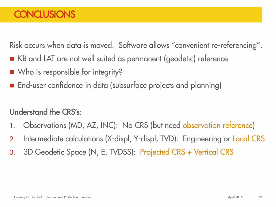
CONCLUSIONS
Risk occurs when data is moved. Software allows “convenient re-referencing”.
KB and LAT are not well suited as permanent (geodetic) reference
Who is responsible for integrity?
End-user confidence in data (subsurface projects and planning)
Understand the CRS’s:
1. Observations (MD, AZ, INC): No CRS (but need observation reference)
2. Intermediate calculations (X-displ, Y-displ, TVD): Engineering or Local CRS
3. 3D Geodetic Space (N, E, TVDSS): Projected CRS + Vertical CRS
29 April 2016

Copyright 2016 Shell Exploration and Production Company
OUTLOOK
Recommendation: Towards absolute geodetic referencing for survey and logs:
Avoid transfer of observations between applications
Clarify data model: local vs. geodetic space (vertical CRS)
Required for unambiguous long term storage; correlate well data to seismic
Increase Geomatics involvement in wellbore vertical referencing
30 April 2016

Copyright 2016 Shell Exploration and Production Company
Q & A
April 2016 31