Embed Size (px)
Citation preview
Architettura degli Elaboratori
Marco Vanneschi
Architetture parallele:
stato e tendenze
15 maggio 2014
Laurea Magistrale
in
Informatica e Networking
Corso
High Performance Computing
Evoluzione della potenza di calcolo / costo
Architettura degli Elaboratori - HPC 3
Milioni di istruzioni al secondo per 1000 $ • Fino ai primi anni 2000: evoluzione della tecnologia della singola CPU,
con frequenza del clock linearmente crescente.
• Successivamente: evoluzione della tecnologia multicore,
con clock 1 GHz.
• Performance e Energy Efficiency.
• 2 linee di tendenza:
Multicore MIMD: programmi paralleli
generali
Multicore SIMD/SIMT: programmi sequenziali con
‘parti accelerate in parallelo’
10 6
10 5
10 4
10 3
1
10-6
1960 1970 1980 1990 2000 2010 2020 2030 2040
MIMD(Multiple Instruction Stream Multiple Data Steam)
e
Multicore / Manycoregenerali
Architettura degli Elaboratori - HPC 4
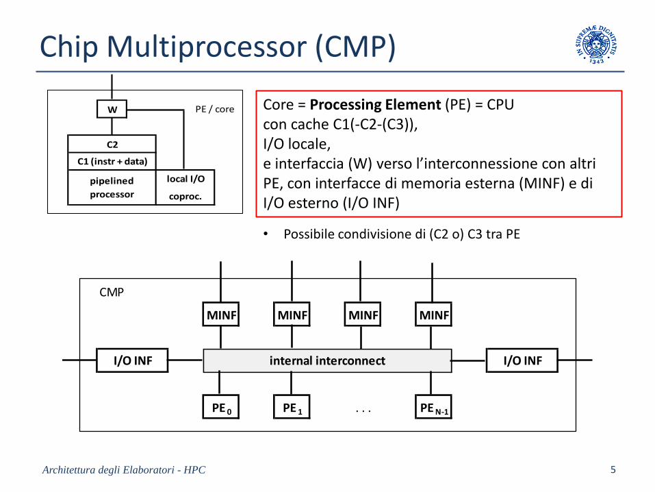
Chip Multiprocessor (CMP)
Architettura degli Elaboratori - HPC 5
W
C2
local I/Opipelined
processor coproc.
C1 (instr + data)
PE / core
CMP
MINF MINF MINF MINF
PE 0 PE 1 . . . PE N-1
internal interconnectI/O INF I/O INF
• Possibile condivisione di (C2 o) C3 tra PE
Core = Processing Element (PE) = CPU con cache C1(-C2-(C3)), I/O locale, e interfaccia (W) verso l’interconnessione con altri PE, con interfacce di memoria esterna (MINF) e di I/O esterno (I/O INF)
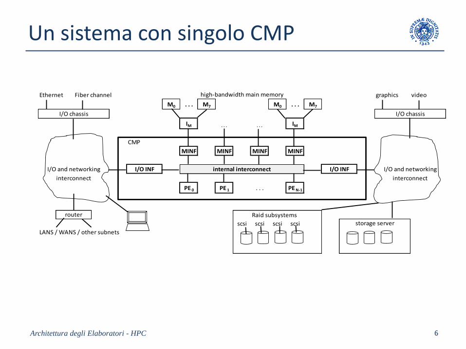
Un sistema con singolo CMP
Architettura degli Elaboratori - HPC 6
Ethernet Fiber channel graphics video
M0 . . . M7 M0 . . . M7
IM . . . . . . IM
CMP
MINF MINF MINF MINF
PE 0 PE 1 . . . PE N-1
Raid subsystems
scsi scsi scsi scsi
LANS / WANS / other subnets
I/O chassis
router
interconnectinterconnect
storage server
I/O and networkingI/O and networking I/O INF internal interconnect I/O INF
high-bandwidth main memory
I/O chassis
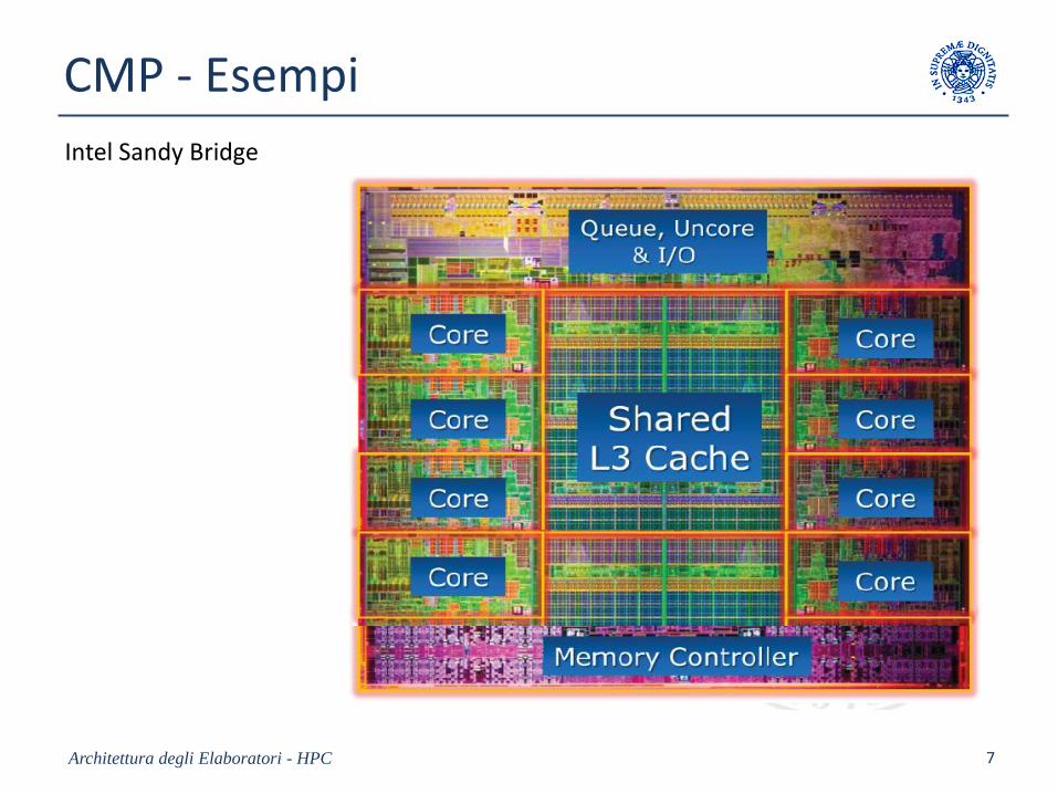
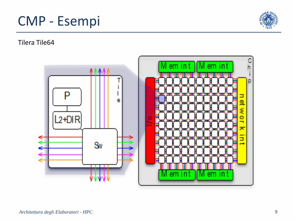
CMP - Esempi
Architettura degli Elaboratori - HPC 7
Intel Sandy Bridge
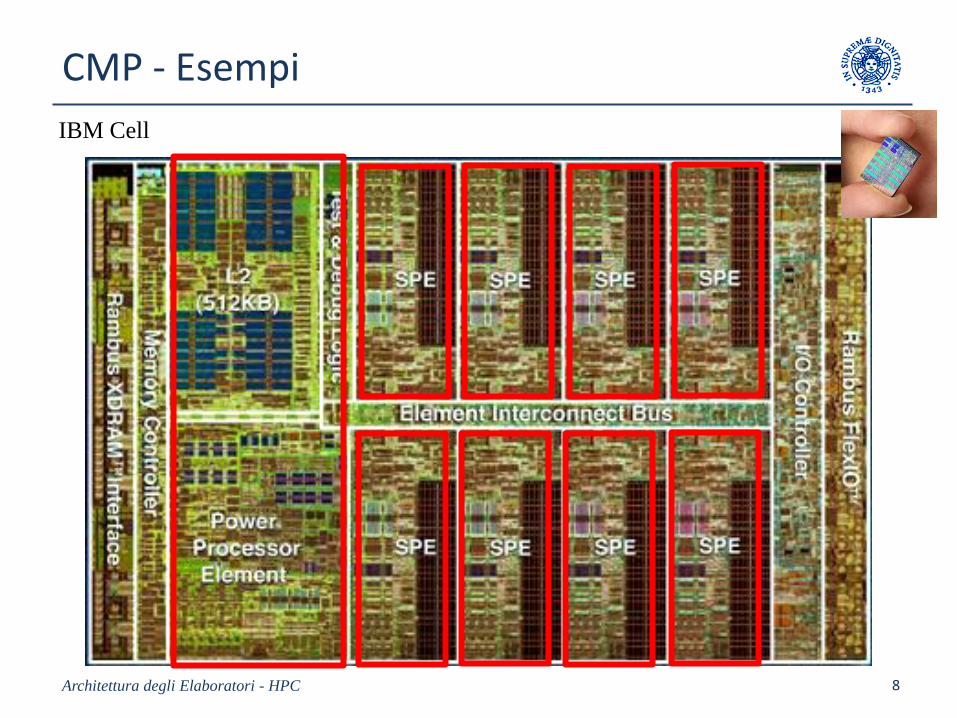
CMP - Esempi
8Architettura degli Elaboratori - HPC
IBM Cell
CMP - Esempi
Architettura degli Elaboratori - HPC 9
Tilera Tile64
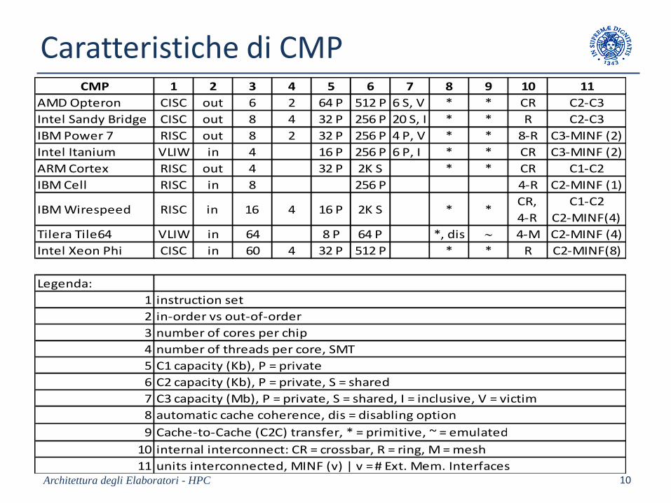
Caratteristiche di CMP
Architettura degli Elaboratori - HPC 10
CMP 1 2 3 4 5 6 7 8 9 10 11
AMD Opteron CISC out 6 2 64 P 512 P 6 S, V * * CR C2-C3
Intel Sandy Bridge CISC out 8 4 32 P 256 P 20 S, I * * R C2-C3
IBM Power 7 RISC out 8 2 32 P 256 P 4 P, V * * 8-R C3-MINF (2)
Intel Itanium VLIW in 4 16 P 256 P 6 P, I * * CR C3-MINF (2)
ARM Cortex RISC out 4 32 P 2K S * * CR C1-C2
IBM Cell RISC in 8 256 P 4-R C2-MINF (1)
IBM Wirespeed RISC in 16 4 16 P 2K S * *CR,
4-R
C1-C2
C2-MINF(4)
Tilera Tile64 VLIW in 64 8 P 64 P *, dis 4-M C2-MINF (4)
Intel Xeon Phi CISC in 60 4 32 P 512 P * * R C2-MINF(8)
Legenda:
1 instruction set
2 in-order vs out-of-order
3 number of cores per chip
4 number of threads per core, SMT
5 C1 capacity (Kb), P = private
6 C2 capacity (Kb), P = private, S = shared
7 C3 capacity (Mb), P = private, S = shared, I = inclusive, V = victim
8 automatic cache coherence, dis = disabling option
9 Cache-to-Cache (C2C) transfer, * = primitive, ~ = emulated
10 internal interconnect: CR = crossbar, R = ring, M = mesh
11 units interconnected, MINF (v) | v = # Ext. Mem. Interfaces
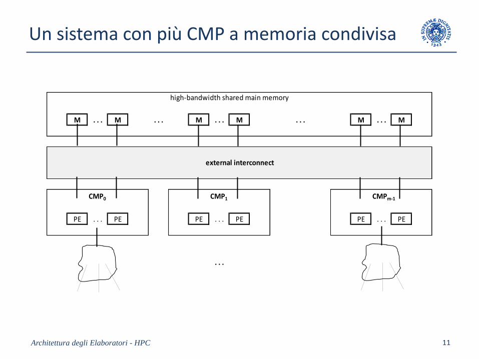
Un sistema con più CMP a memoria condivisa
Architettura degli Elaboratori - HPC 11
M . . . M . . . M . . . M . . . M . . . M
CMP0 CMP1 CMPm-1
PE . . . PE PE . . . PE PE . . . PE
. . .
external interconnect
high-bandwidth shared main memory
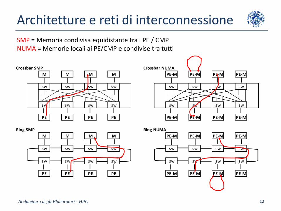
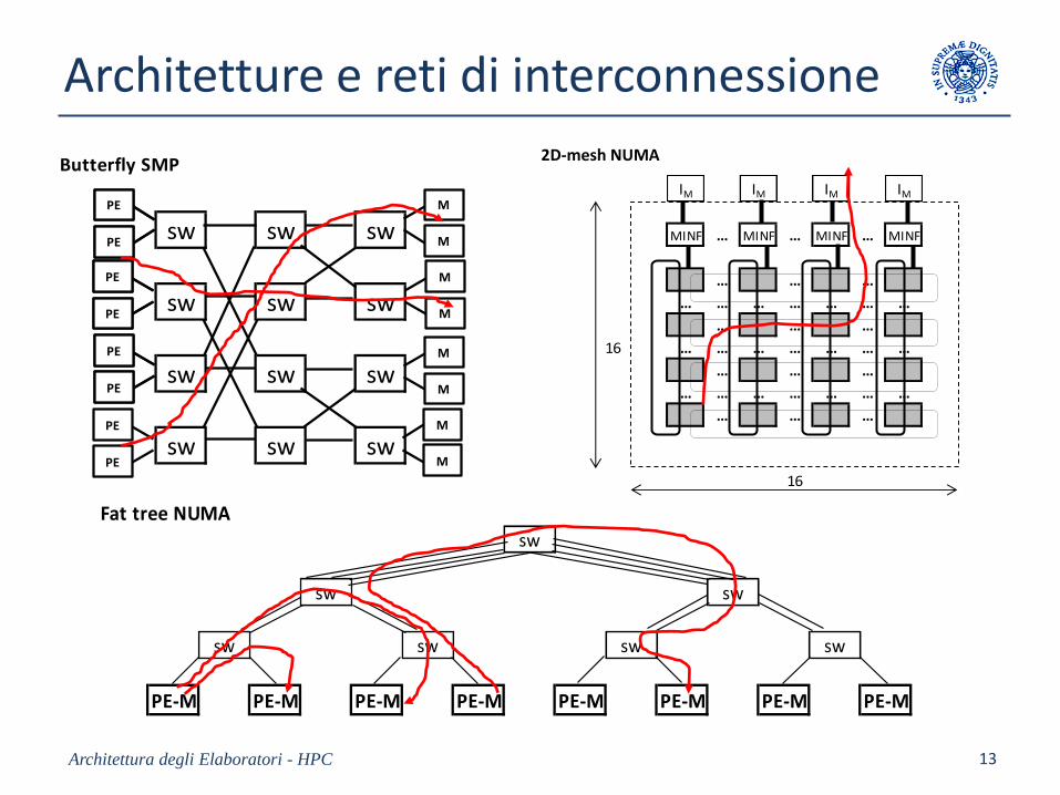
Architetture e reti di interconnessione
Architettura degli Elaboratori - HPC 12
Crossbar SMP Crossbar NUMA
M M M M PE-M PE-M PE-M PE-M
sw sw sw sw sw sw sw sw
sw sw sw sw sw sw sw sw
PE PE PE PE PE-M PE-M PE-M PE-M
Ring SMP Ring NUMA
M M M M PE-M PE-M PE-M PE-M
sw sw sw sw sw sw sw sw
sw sw sw sw sw sw sw sw
PE PE PE PE PE-M PE-M PE-M PE-M
SMP = Memoria condivisa equidistante tra i PE / CMPNUMA = Memorie locali ai PE/CMP e condivise tra tutti
Architetture e reti di interconnessione
Architettura degli Elaboratori - HPC 13
Butterfly SMP 2D-mesh NUMA
sw sw sw
sw sw sw
sw sw sw
sw sw sw sw sw sw
sw sw sw
sw sw sw
PE-MPE
PE
PE
PE
PE
PE
PE
PE
PE
PE
PE
PE
M
M
M
M
M
M
M
M
PE-M PE-M
PE-M PE-M PE-M
PE-M PE-M PE-MPE
PE
Fat tree NUMAsw
sw sw
sw sw sw sw
PE-M PE-M PE-M PE-M PE-M PE-M PE-M PE-M
IM IM IM IM
MINF … MINF … MINF … MINF
… … …
… … … … … … …
… … …
16 … … … … … … …
… … …
… … … … … … …
… … …
16
2D-mesh NUMA
Cache coherence
If the a shared block is loaded into more than one cache,
all copies must be identical (consistent) each other and identical to the value in sharedMain Memory.
Architettura degli Elaboratori - HPC 14
M
Pi Ci Pj Cj
. . . . . . . . .
S
S S
S (block) is loaded into Ci
and Cj.
No consistency problem if
S is used in a read-only
mode by Pi and Pj.
If Pi modifies its S copy,
then the copy in Cj is
inconsistent (in general).
Automatic (programmer invisible) coherence at firmware level, or by program.
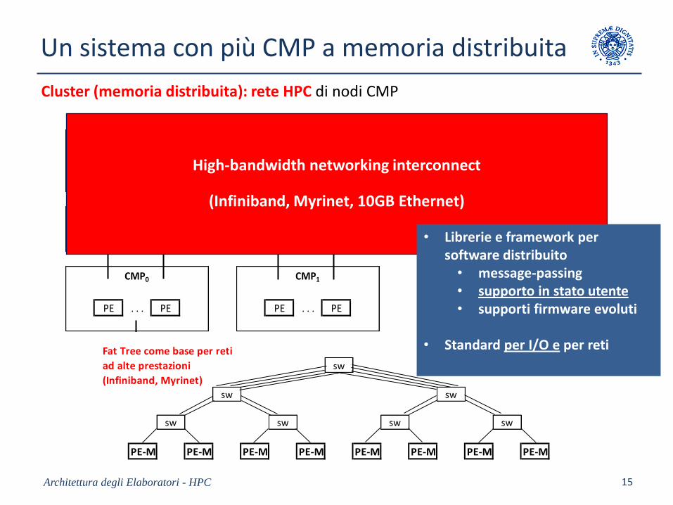
Un sistema con più CMP a memoria distribuita
Architettura degli Elaboratori - HPC 15
M . . . M . . . M . . . M . . . M . . . M
CMP0 CMP1 CMPm-1
PE . . . PE PE . . . PE PE . . . PE
. . .
external interconnect
high-bandwidth shared main memory
Cluster (memoria distribuita): rete HPC di nodi CMP
High-bandwidth networking interconnect
(Infiniband, Myrinet, 10GB Ethernet)
Fat Tree come base per reti
ad alte prestazioni sw
(Infiniband, Myrinet)
sw sw
sw sw sw sw
PE-M PE-M PE-M PE-M PE-M PE-M PE-M PE-M
• Librerie e framework per software distribuito
• message-passing• supporto in stato utente• supporti firmware evoluti
• Standard per I/O e per reti
Highly parallel MIMD
• Is it feasible to build ‘general-purpose’ MIMD machines with a very high number of cores (103) per chip ?
• Is it feasible to achieve good energy efficiency with 103
‘general’ cores per chip ?
Architettura degli Elaboratori - HPC 16
Energy efficient ‘general’ processors
• In-order vs out-of-order– In-order exploits compile-time reordering and FIFO out-of-ordering (no
additional firmware complexity)
– Out-of-order includes general data-flow execution and branch prediction
(serious additional firmware complexity)
• With the same area and power per chip:
in-order cores / out-of-order cores = from 5 to 10
• References: Larrabee (x86), IBM Power, Cell, Wire-Speed– they are examples of in-order MIMD architectures – other examples exist
• RISC vs CISC: the ratio increases at least by a factor 2-3.– unless the area gain is used in RISC for additional resources (FU, registers, …)
Architettura degli Elaboratori - HPC 17
Energy efficient highly parallel MIMD
In-order vs out-of-order
Hardware multithreading
• Area and power are not substantially affected by hardware multithreading– < 10% area or power increase per thread (wrt 30 % average bandwidth improvement (?))
• With multithreading, out-of-order performance gain isnegligible for single programs.
Rationale on status and trends:
in-order RISC multithreaded cores per chip: 103 is realistic with current VLSI technology:
– Better throughput than out-of-order CISC, with the same area and power
– Raw computational latency (Floating Point) is re-gained through additional FUs and VPUs
– Compiler technology is strategic (again) - VLIW
– Not severely limited by the application class (trade-off generality vs performance)
• Current examples: Adapteva Epiphany, ST Microelectronics, and others.
Architettura degli Elaboratori - HPC 18
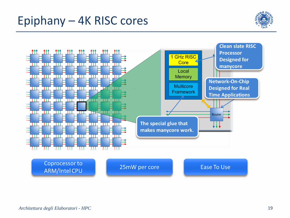
Epiphany – 4K RISC cores
Architettura degli Elaboratori - HPC 19
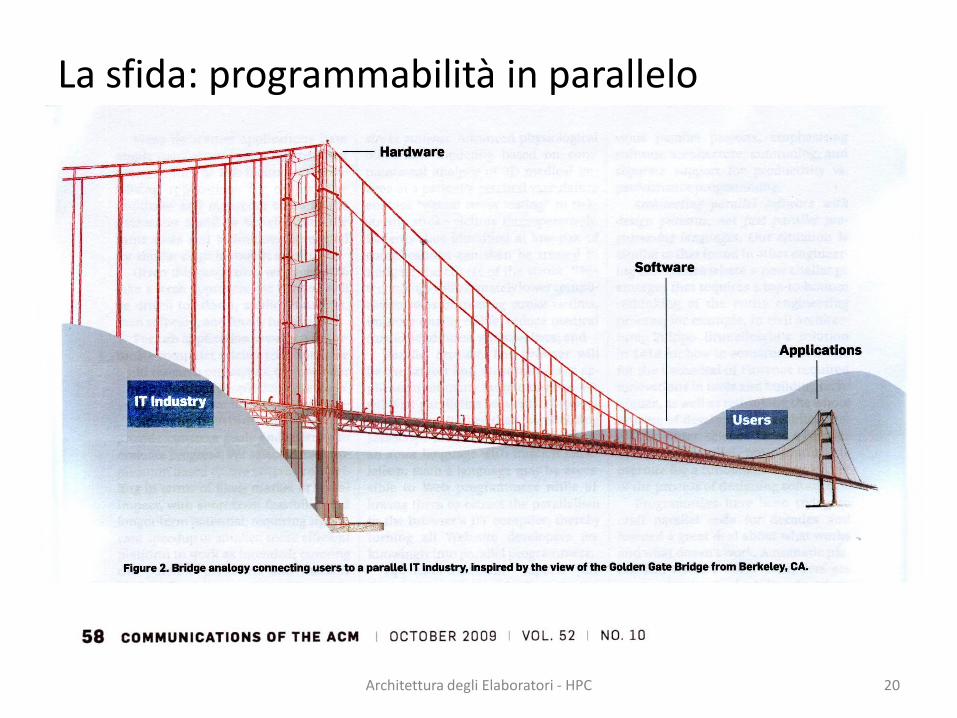
La sfida: programmabilità in parallelo
Architettura degli Elaboratori - HPC 20
SIMD(Single Instruction Stream Multiple Data Steam)
e
Estensioni per Vettorizzazione
GPU
Architettura degli Elaboratori - HPC 21
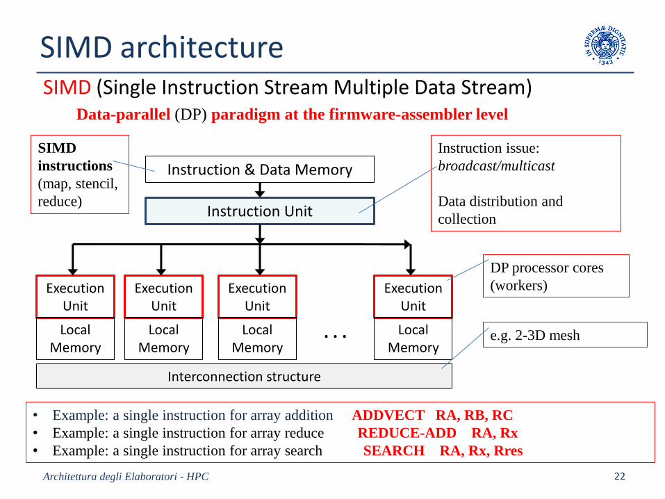
SIMD architectureSIMD (Single Instruction Stream Multiple Data Stream)
Data-parallel (DP) paradigm at the firmware-assembler level
Architettura degli Elaboratori - HPC 22
Instruction & Data Memory
Instruction Unit
ExecutionUnit
ExecutionUnit
ExecutionUnit
ExecutionUnit
LocalMemory
LocalMemory
LocalMemory
LocalMemory
. . .
Interconnection structure
SIMD
instructions
(map, stencil,
reduce)
Instruction issue:
broadcast/multicast
Data distribution and
collection
DP processor cores
(workers)
• Example: a single instruction for array addition ADDVECT RA, RB, RC
• Example: a single instruction for array reduce REDUCE-ADD RA, Rx
• Example: a single instruction for array search SEARCH RA, Rx, Rres
e.g. 2-3D mesh
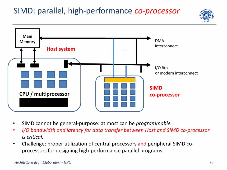
SIMD: parallel, high-performance co-processor
Architettura degli Elaboratori - HPC 23
.
.
.
MainMemory
. . .
CPU / multiprocessor
I/O Bus or modern interconnect
DMA interconnect
SIMD co-processor
• SIMD cannot be general-purpose: at most can be programmable.• I/O bandwidth and latency for data transfer between Host and SIMD co-processor
is critical.• Challenge: proper utilization of central processors and peripheral SIMD co-
processors for designing high-performance parallel programs
Host system
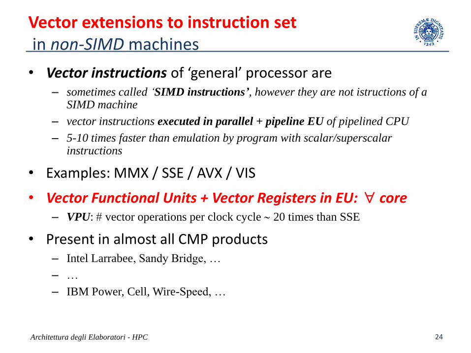
Vector extensions to instruction setin non-SIMD machines
• Vector instructions of ‘general’ processor are – sometimes called ‘SIMD instructions’, however they are not istructions of a
SIMD machine
– vector instructions executed in parallel + pipeline EU of pipelined CPU
– 5-10 times faster than emulation by program with scalar/superscalar instructions
• Examples: MMX / SSE / AVX / VIS
• Vector Functional Units + Vector Registers in EU: core– VPU: vector operations per clock cycle 20 times than SSE
• Present in almost all CMP products– Intel Larrabee, Sandy Bridge, …
– …
– IBM Power, Cell, Wire-Speed, …
Architettura degli Elaboratori - HPC 24
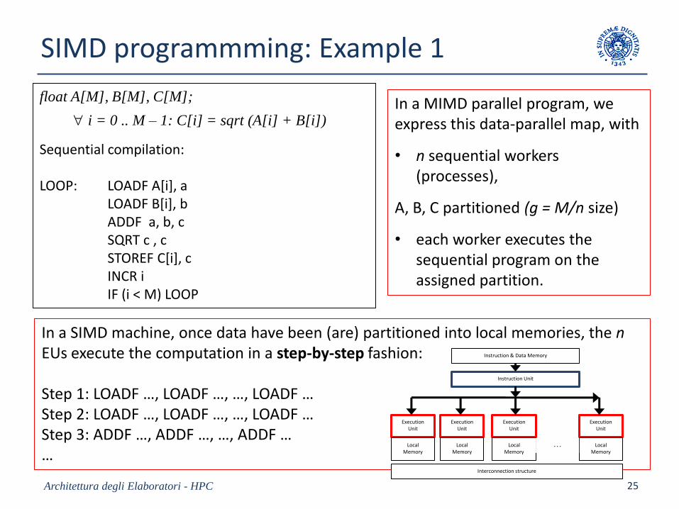
SIMD programmming: Example 1
float A[M], B[M], C[M];
i = 0 .. M – 1: C[i] = sqrt (A[i] + B[i])
Sequential compilation:
LOOP: LOADF A[i], a LOADF B[i], bADDF a, b, cSQRT c , cSTOREF C[i], c INCR iIF (i < M) LOOP
Architettura degli Elaboratori - HPC 25
In a MIMD parallel program, weexpress this data-parallel map, with
• n sequential workers(processes),
A, B, C partitioned (g = M/n size)
• each worker executes the sequential program on the assigned partition.
In a SIMD machine, once data have been (are) partitioned into local memories, the nEUs execute the computation in a step-by-step fashion:
Step 1: LOADF …, LOADF …, …, LOADF …Step 2: LOADF …, LOADF …, …, LOADF …Step 3: ADDF …, ADDF …, …, ADDF ……
Instruction & Data Memory
Instruction Unit
ExecutionUnit
ExecutionUnit
ExecutionUnit
ExecutionUnit
LocalMemory
LocalMemory
LocalMemory
LocalMemory
. . .
Interconnection structure
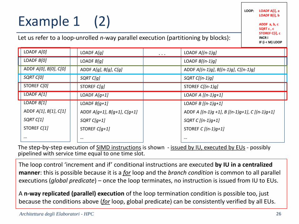
Example 1 (2)Let us refer to a loop-unrolled n-way parallel execution (partitioning by blocks):
Architettura degli Elaboratori - HPC 26
LOADF A[0]
LOADF B[0]
ADDF A[0], B[0], C[0]
SQRT C[0]
STOREF C[0]
LOADF A[1]
LOADF B[1]
ADDF A[1], B[1], C[1]
SQRT C[1]
STOREF C[1]
…
LOADF A[g]
LOADF B[g]
ADDF A[g], B[g], C[g]
SQRT C[g]
STOREF C[g]
LOADF A[g+1]
LOADF B[g+1]
ADDF A[g+1], B[g+1], C[g+1]
SQRT C[g+1]
STOREF C[g+1]
…
LOADF A[(n-1)g]
LOADF B[(n-1)g]
ADDF A[(n-1)g], B[(n-1)g], C[(n-1)g]
SQRT C[(n-1)g]
STOREF C[(n-1)g]
LOADF A [(n-1)g+1]
LOADF B [(n-1)g+1]
ADDF A [(n-1)g +1], B [(n-1)g+1], C [(n-1)g+1]
SQRT C [(n-1)g+1]
STOREF C [(n-1)g+1]
…
. . .
The step-by-step execution of SIMD instructions is shown - issued by IU, executed by EUs - possiblypipelined with service time equal to one time slot.
The loop control ‘increment and if’ conditional instructions are executed by IU in a centralizedmanner: this is possible because it is a for loop and the branch condition is common to all parallel executions (global predicate) – once the loop terminates, no instruction is issued from IU to EUs.
A n-way replicated (parallel) execution of the loop termination condition is possible too, just because the conditions above (for loop, global predicate) can be consistently verified by all EUs.
LOOP: LOADF A[i], a LOADF B[i], b
ADDF a, b, cSQRT c , cSTOREF C[i], c INCR iIF (i < M) LOOP
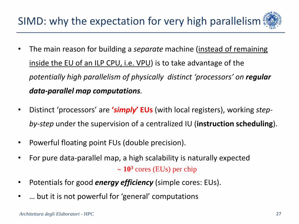
SIMD: why the expectation for very high parallelism
• The main reason for building a separate machine (instead of remaining
inside the EU of an ILP CPU, i.e. VPU) is to take advantage of the
potentially high parallelism of physically distinct ‘processors’ on regular
data-parallel map computations.
• Distinct ‘processors’ are ‘simply’ EUs (with local registers), working step-
by-step under the supervision of a centralized IU (instruction scheduling).
• Powerful floating point FUs (double precision).
• For pure data-parallel map, a high scalability is naturally expected
103 cores (EUs) per chip
• Potentials for good energy efficiency (simple cores: EUs).
• … but it is not powerful for ‘general’ computations
Architettura degli Elaboratori - HPC 27
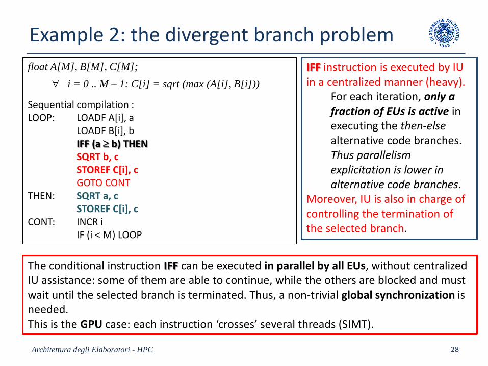
Example 2: the divergent branch problem
Architettura degli Elaboratori - HPC 28
float A[M], B[M], C[M];
i = 0 .. M – 1: C[i] = sqrt (max (A[i], B[i]))
Sequential compilation :LOOP: LOADF A[i], a
LOADF B[i], bIFF (a b) THENSQRT b, cSTOREF C[i], cGOTO CONT
THEN: SQRT a, cSTOREF C[i], c
CONT: INCR iIF (i < M) LOOP
IFF instruction is executed by IU in a centralized manner (heavy).
For each iteration, only a fraction of EUs is active in executing the then-else alternative code branches.Thus parallelism explicitation is lower in alternative code branches.
Moreover, IU is also in charge of controlling the termination of the selected branch.
The conditional instruction IFF can be executed in parallel by all EUs, without centralizedIU assistance: some of them are able to continue, while the others are blocked and must wait until the selected branch is terminated. Thus, a non-trivial global synchronization isneeded. This is the GPU case: each instruction ‘crosses’ several threads (SIMT).
GPU(Graphics Processing Units)
e
GP-GPU(General Purpose – GPU)
Architettura degli Elaboratori - HPC 29
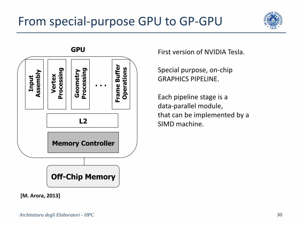
From special-purpose GPU to GP-GPU
Architettura degli Elaboratori - HPC 30
GPU
. . .
Inp
ut
Asse
mb
ly
Ve
rte
x
Pro
ce
ssin
g
Fra
me
Bu
ffe
r O
pe
rati
on
sL2
Memory Controller
Off-Chip Memory
Ge
om
etr
y
Pro
ce
ssin
g
First version of NVIDIA Tesla.
Special purpose, on-chipGRAPHICS PIPELINE.
Each pipeline stage is a data-parallel module, that can be implemented by a SIMD machine.
[M. Arora, 2013]
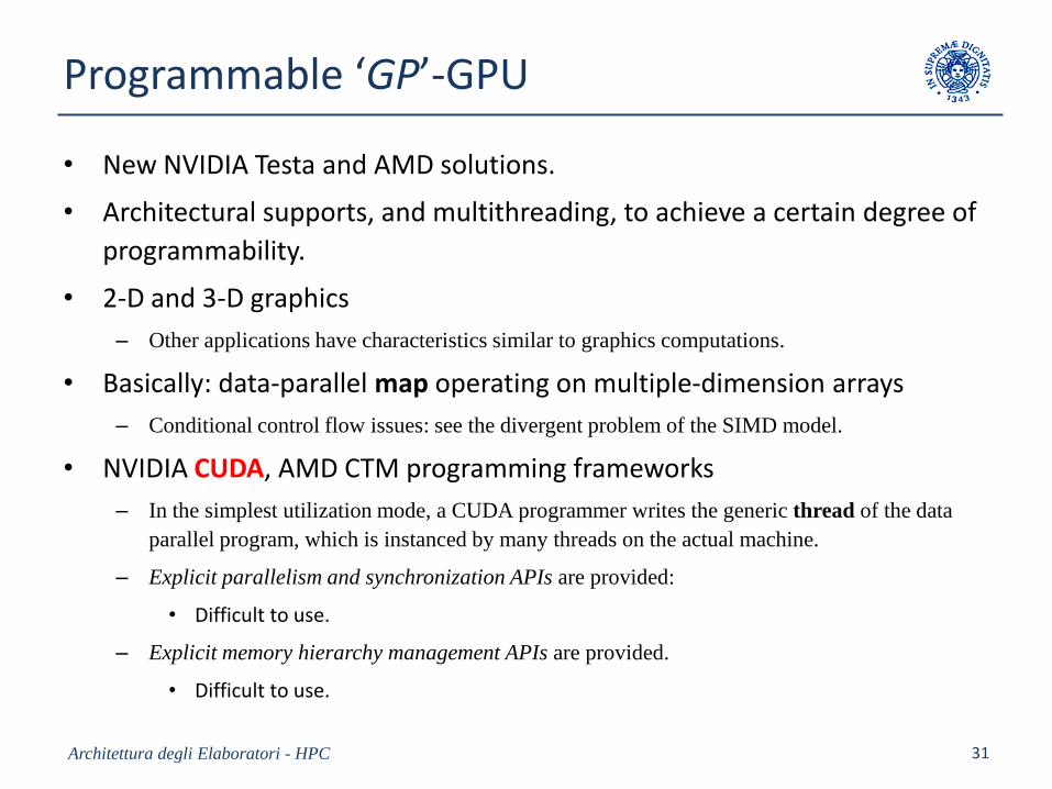
Programmable ‘GP’-GPU
• New NVIDIA Testa and AMD solutions.
• Architectural supports, and multithreading, to achieve a certain degree of
programmability.
• 2-D and 3-D graphics
– Other applications have characteristics similar to graphics computations.
• Basically: data-parallel map operating on multiple-dimension arrays
– Conditional control flow issues: see the divergent problem of the SIMD model.
• NVIDIA CUDA, AMD CTM programming frameworks
– In the simplest utilization mode, a CUDA programmer writes the generic thread of the data
parallel program, which is instanced by many threads on the actual machine.
– Explicit parallelism and synchronization APIs are provided:
• Difficult to use.
– Explicit memory hierarchy management APIs are provided.
• Difficult to use.
Architettura degli Elaboratori - HPC 31
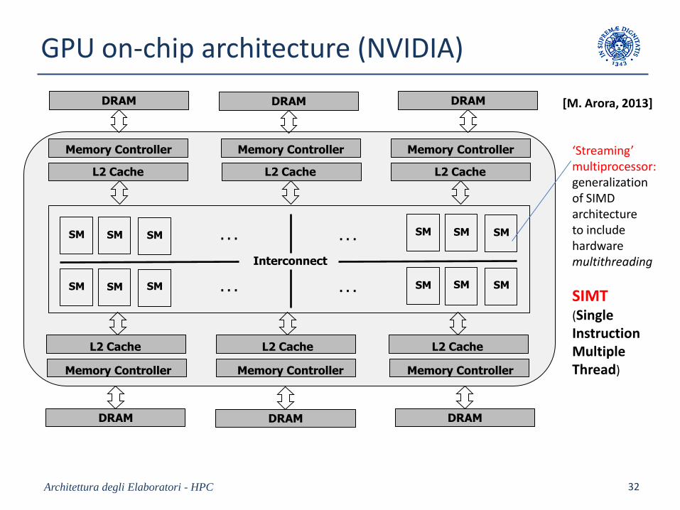
GPU on-chip architecture (NVIDIA)
Architettura degli Elaboratori - HPC 32
Memory Controller Memory Controller Memory Controller
Memory Controller Memory Controller Memory Controller
L2 Cache L2 Cache L2 Cache
L2 Cache L2 Cache L2 Cache
SM SM SM
SM SM SM
SM SM SM
SM SM SM
Interconnect
. . .
. . .
. . .
. . .
DRAM DRAM DRAM
DRAM DRAM DRAM
‘Streaming’ multiprocessor:generalizationof SIMD architectureto include hardware multithreading
SIMT(Single Instruction Multiple Thread)
[M. Arora, 2013]
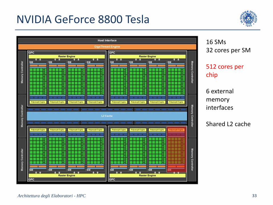
NVIDIA GeForce 8800 Tesla
Architettura degli Elaboratori - HPC 33
16 SMs32 cores per SM
512 cores per chip
6 externalmemory interfaces
Shared L2 cache
SIMT (Single Instruction Multiple Thread)
Architettura degli Elaboratori - HPC 34
Let us organize our data-parallel computation in a (possibly large) number of functionally identicalhardware threads, e.g.
i = 0 .. M – 1: C[i] = sqrt (A[i] + B[i])
A SM is composed of 32 cores, eachone mapping a hardware thread.
A group of 32 threads (called‘Warp’) is executed by a SM.
Up to 48 Warps = 1536 threads(Fermi).
A SIMT instruction (generalizationof SIMD instruction) is composed by 32 scalar instructions, one for eachthread.
Thus, 32 instructions per time slot are issued.
thread
A B C A B C A B C. . .
A B C A B C A B C. . .
A B C A B C A B C. . .
. . . . . . . . .
partitions
SIMT instruction
thread group =
Warp
48
32
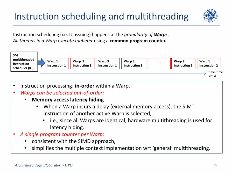
Instruction scheduling and multithreading
Architettura degli Elaboratori - HPC 35
Warp 1Instruction 1
Warp 2Instruction 1
Warp 3Instruction 1
Warp 3Instruction 2
. . . Warp 2Instruction 2
Warp 1Instruction 2
time (time slots)
SM multithreaded instructionscheduler (IU)
• Instruction processing: in-order within a Warp.• Warps can be selected out-of-order:
• Memory access latency hiding• When a Warp incurs a delay (external memory access), the SIMT
instruction of another active Warp is selected,• i.e., since all Warps are identical, hardware multithreading is used for
latency hiding.• A single program counter per Warp:
• consistent with the SIMD approach,• simplifies the multiple context implementation wrt ‘general’ multithreading.
Instruction scheduling (i.e. IU issuing) happens at the granularity of Warps.All threads in a Warp execute togheter using a common program counter.
GPU architecture and energy efficiency
• Efficient memory hierarchy for the specific class of computations:– 6 high-bandwidth DRAMs, on-chip L2 cache.
– Local memory per thread, global memory per Warp.
– Multithreading-based latency hiding is defined according to the (sufficiently) predictablememory model.
• Thread switching: every 2 – 4 clock cycles.
• The simplicity of cores reduces power consumption and allows GPU to exploit a massively large number of cores, i.e. order 103 ( 500 in GeForce8800 Tesla, 1000 in GTX 280 Tesla and GF 100 Fermi, 2900 in GK 110 Kepler).
• However, the architectural solutions for– dynamic SIMT instruction formation (not VLIW)
– divergent branch problem
– intra-SM synchronization, inter-SM synchronization
re-introduce a certain level of complexity,
though the whole architecture remains energy efficient.
Architettura degli Elaboratori - HPC 36
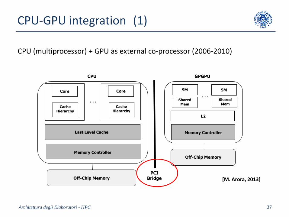
CPU-GPU integration (1)
Architettura degli Elaboratori - HPC 37
L2
SM SM
Shared Mem
Shared Mem
. . .
GPGPU
Memory Controller
Off-Chip Memory
PCIBridgeOff-Chip Memory
Last Level Cache
Core
CacheHierarchy
Core
CacheHierarchy
CPU
. . .
Memory Controller
CPU (multiprocessor) + GPU as external co-processor (2006-2010)
[M. Arora, 2013]
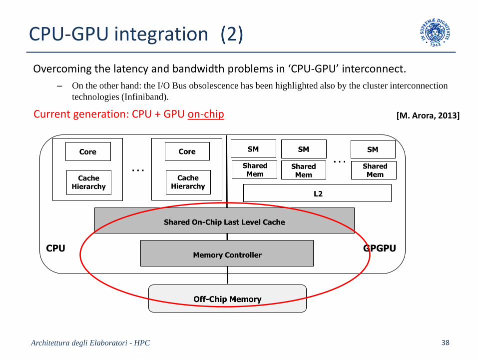
CPU-GPU integration (2)
Architettura degli Elaboratori - HPC 38
Current generation: CPU + GPU on-chip [M. Arora, 2013]
L2
Off-Chip Memory
Shared On-Chip Last Level Cache
Core
CacheHierarchy
Core
CacheHierarchy
SM
Shared Mem
SM SM
Shared Mem
Shared Mem
CPU
. . .. . .
GPGPUMemory Controller
Overcoming the latency and bandwidth problems in ‘CPU-GPU’ interconnect.
– On the other hand: the I/O Bus obsolescence has been highlighted also by the cluster interconnection
technologies (Infiniband).
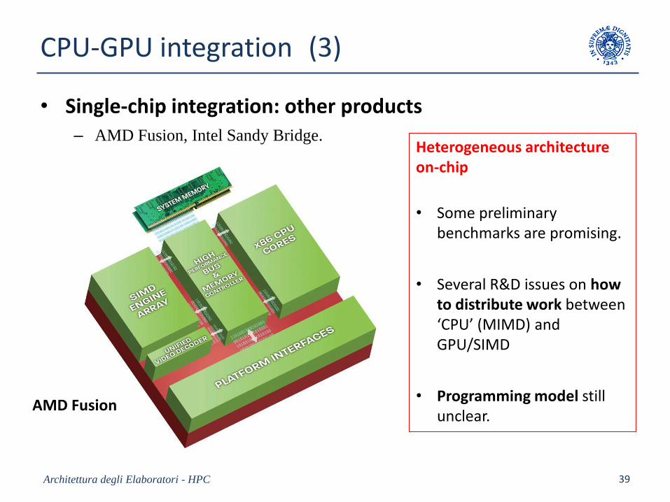
CPU-GPU integration (3)
• Single-chip integration: other products– AMD Fusion, Intel Sandy Bridge.
Architettura degli Elaboratori - HPC 39
AMD Fusion
Heterogeneous architectureon-chip
• Some preliminarybenchmarks are promising.
• Several R&D issues on howto distribute work between‘CPU’ (MIMD) and GPU/SIMD
• Programming model stillunclear.
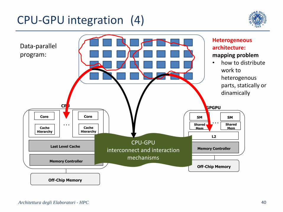
CPU-GPU integration (4)
Architettura degli Elaboratori - HPC 40
L2
SM SM
Shared Mem
Shared Mem
. . .
GPGPU
Memory Controller
Off-Chip Memory
Off-Chip Memory
Last Level Cache
Core
CacheHierarchy
Core
CacheHierarchy
CPU
. . .
Memory Controller
CPU-GPUinterconnect and interaction
mechanisms
Data-parallel program:
Heterogeneousarchitecture:mapping problem• how to distribute
work to heterogenousparts, statically or dinamically
Conclusion
Highly-parallel on-chip architectures for high performance and energyefficiency
– two main approaches:
1. MIMD with vectorization core, or with internal co-processors CMP (customer-defined, e.g. network programming)
– Potentials for technological feasibility with in-order RISC multithreaded cores
– Application generality and uniform programming model
• Co-processors used uniformly as (I/O) processes
– Compiler technology evolution is needed for energy efficiency.
2. Integrated MIMD + SIMD (SIMT / GPU)– Technological feasibility already demonstrated
– Generality vs performance trade-off: far from being formalized and solved
– Much more programmability is needed
– More advanvced software technology and compiler evolution are needed.
Architettura degli Elaboratori - HPC 41