Embed Size (px)
Citation preview
ASSEMBLY INSTRUCTIONS
SS2015
BASE SIZE: 2.020m x 1.520m

2
BEFORE YOU START:
Read all instructions carefully
Identify all parts and check quantities against parts list
Select a level site
Do not mark cladding with pencil as lead can cause corrosion to cladding
SAFETY:
Do not attempt to build your shed in high winds
Beware of sharp edges, recommend use of gloves
Protect your eyes and ears
For ease of assembly, use a friend to help
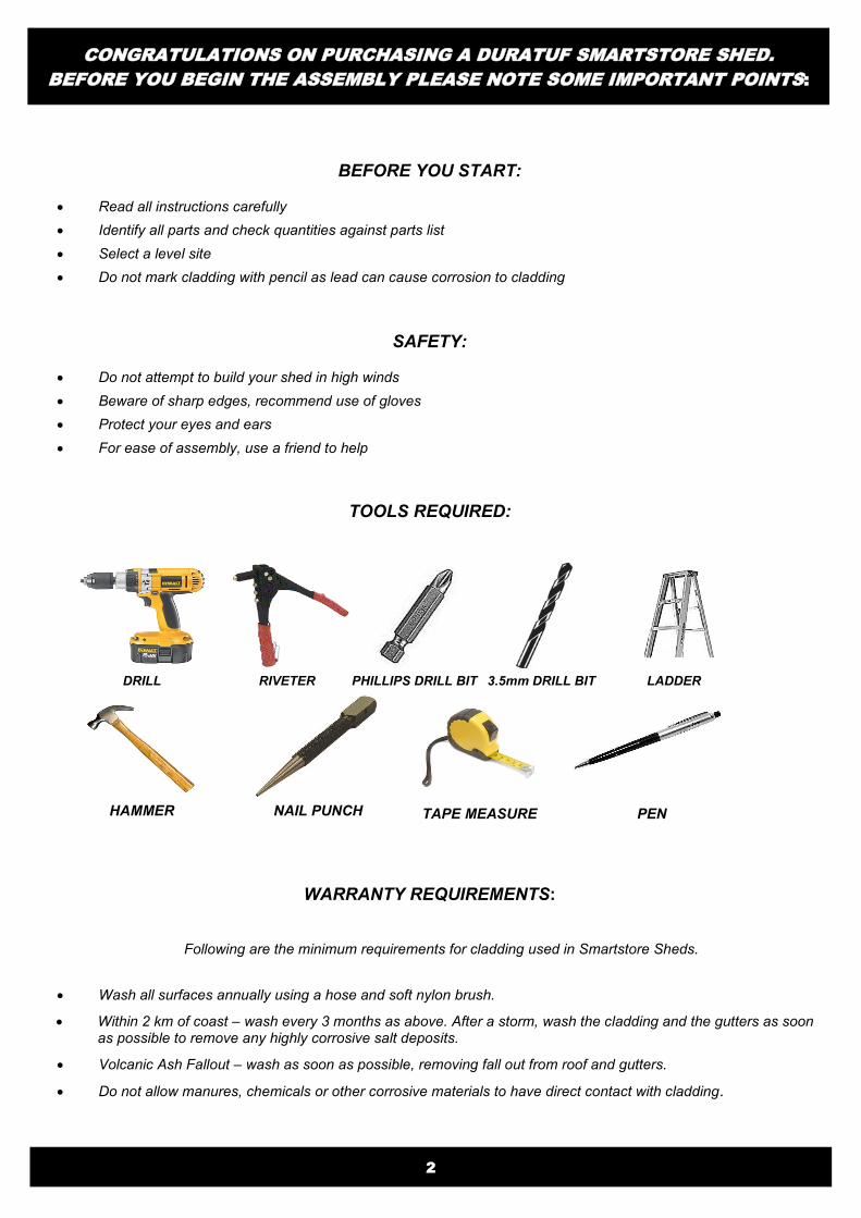
TOOLS REQUIRED:
WARRANTY REQUIREMENTS:
Following are the minimum requirements for cladding used in Smartstore Sheds.
Wash all surfaces annually using a hose and soft nylon brush.
Within 2 km of coast – wash every 3 months as above. After a storm, wash the cladding and the gutters as soon as possible to remove any highly corrosive salt deposits.
Volcanic Ash Fallout – wash as soon as possible, removing fall out from roof and gutters.
Do not allow manures, chemicals or other corrosive materials to have direct contact with cladding.
DRILL RIVETER PHILLIPS DRILL BIT 3.5mm DRILL BIT
HAMMER
LADDER
TAPE MEASURE PEN NAIL PUNCH
CONGRATULATIONS ON PURCHASING A DURATUF SMARTSTORE SHED.
BEFORE YOU BEGIN THE ASSEMBLY PLEASE NOTE SOME IMPORTANT POINTS:
3
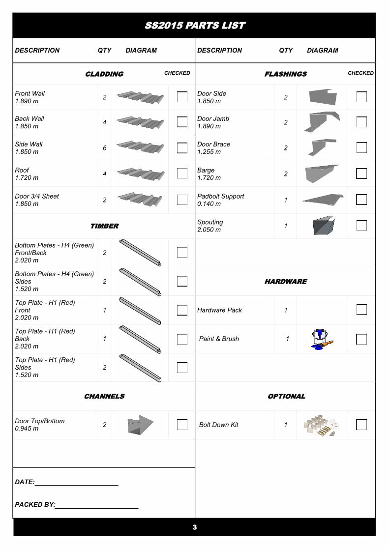
SS2015 PARTS LIST
DESCRIPTION QTY DIAGRAM DESCRIPTION QTY DIAGRAM
CLADDING FLASHINGS
Front Wall 1.890 m
2
Door Side 1.850 m
2
Back Wall 1.850 m
4
Door Jamb 1.890 m
2
Side Wall 1.850 m
6
Door Brace 1.255 m
2
Roof 1.720 m
4
Barge 1.720 m
2
Door 3/4 Sheet 1.850 m
2
Padbolt Support 0.140 m
1
TIMBER Spouting 2.050 m
1
Bottom Plates - H4 (Green) Front/Back 2.020 m
2
Bottom Plates - H4 (Green) Sides 1.520 m
2
HARDWARE
Top Plate - H1 (Red) Front 2.020 m
1 Hardware Pack 1
Top Plate - H1 (Red) Back 2.020 m
1
Paint & Brush 1
Top Plate - H1 (Red) Sides 1.520 m
2
CHANNELS OPTIONAL
Door Top/Bottom 0.945 m
2
Bolt Down Kit 1
DATE:
PACKED BY:
CHECKED CHECKED
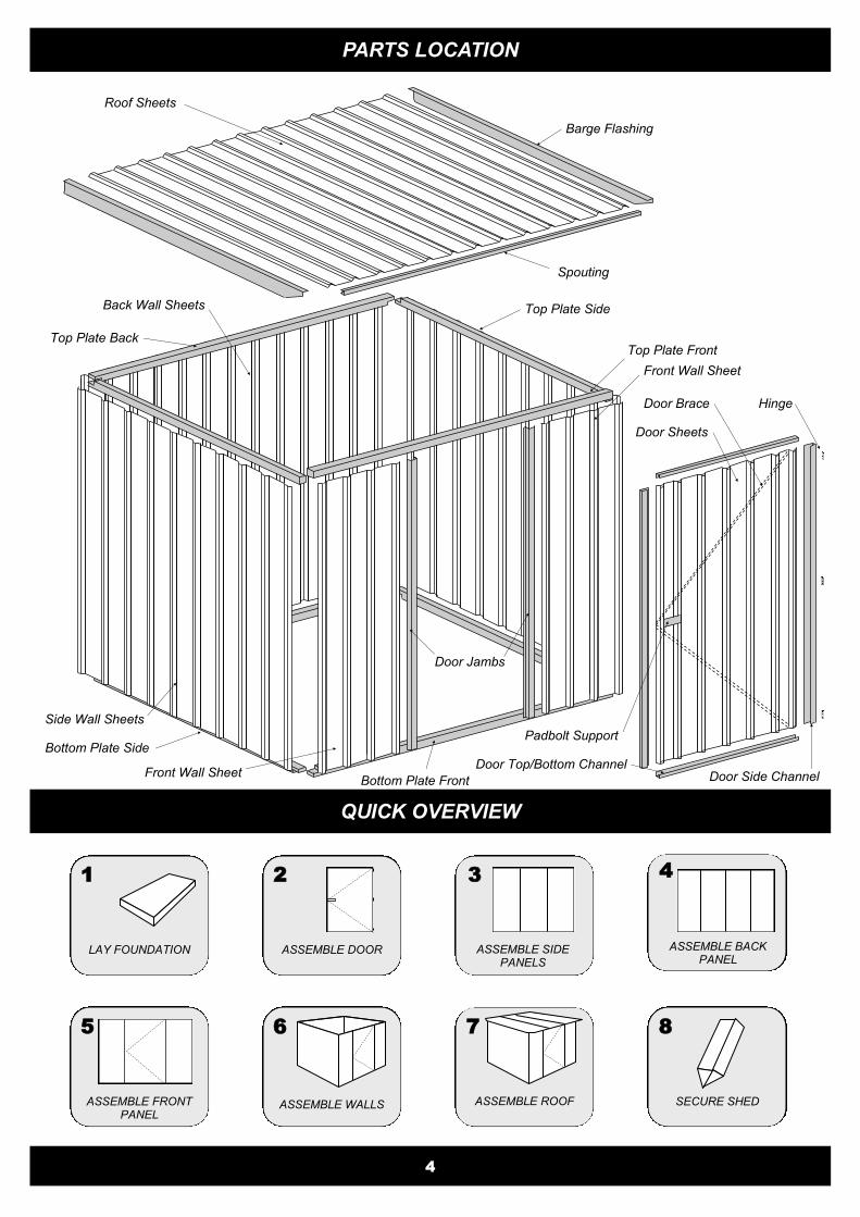
PARTS LOCATION
Side Wall Sheets
Barge Flashing
Spouting
Roof Sheets
Top Plate Side
Top Plate Front
Bottom Plate Front
Bottom Plate Side
Back Wall Sheets
Front Wall Sheet
Door Jambs
Front Wall Sheet
Door Sheets
Door Side Channel
Padbolt Support
Hinge Door Brace
Door Top/Bottom Channel
1
LAY FOUNDATION
2
ASSEMBLE DOOR
3
ASSEMBLE SIDE PANELS
5
ASSEMBLE FRONT PANEL
6
ASSEMBLE WALLS
7
ASSEMBLE ROOF
8
SECURE SHED
4
4
ASSEMBLE BACK PANEL
Top Plate Back
QUICK OVERVIEW

FOUNDATION
SMARTSTORE WOODEN FLOOR The optional Smartstore kitset wooden floor is precut and
designed to be fitted into the shed after the shed is assembled.
Assemble shed as per instructions and fit floor last.
(see page 12 for details).
CONCRETE SLAB FOR RAISED BASE PLATE SHED To build a raised concrete slab for your shed to sit on, we recom-mend the following:
The raised slab size should be 15mm smaller than the base
size of the shed and at least 30mm above ground line.
The slab should be 80mm thick in the middle and 100mm
thick around the edges.
The slab should be laid on a solid or compacted base.
Plastic sheeting under slab will prevent moisture coming
through from underneath.
During construction, you may raise the bottom timber
plate to allow the wall cladding to protrude 20mm below
the bottom plate. This will stop water flowing between
the bottom plate and the concrete floor.
See note on page 7.
80mm 100mm
7.5mm
20mm
Concrete Floor
Base Plate
Wall Cladding
5
RAISED BASE PLATE OPTION (For sheds placed on a raised concrete floor)
No doubt by now you will have decided what sort of base you are putting down. Please read the section that applies to your situation. If you choose to pour a concrete base you will need to decide whether you wish to raise the base plate of your shed. This allows the cladding to protrude below the surface of the concrete and ensures a water tight pad. See concrete pad specifications below By choosing this option you will need to make the pad to the specification below.
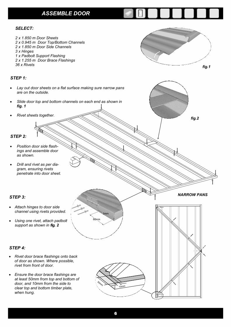
ASSEMBLE DOOR
6
SELECT: 2 x 1.850 m Door Sheets 2 x 0.945 m Door Top/Bottom Channels 2 x 1.850 m Door Side Channels 3 x Hinges 1 x Padbolt Support Flashing 2 x 1.255 m Door Brace Flashings 36 x Rivets
fig.1
STEP 1: Lay out door sheets on a flat surface making sure narrow pans
are on the outside.
Slide door top and bottom channels on each end as shown in fig. 1
Rivet sheets together.
STEP 2: Position door side flash-
ings and assemble door as shown.
Drill and rivet as per dia-gram, ensuring rivets penetrate into door sheet.
STEP 4:
Rivet door brace flashings onto back of door as shown. Where possible, rivet from front of door.
Ensure the door brace flashings are at least 50mm from top and bottom of door, and 10mm from the side to clear top and bottom timber plate, when hung.
fig.2
STEP 3: Attach hinges to door side
channel using rivets provided.
Using one rivet, attach padbolt support as shown in fig. 2
NARROW PANS
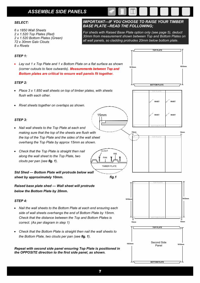
ASSEMBLE SIDE PANELS
SELECT: 6 x 1850 Wall Sheets
2 x 1.520 Top Plates (Red) 2 x 1.520 Bottom Plates (Green) 72 x 30mm Galv Clouts
8 x Rivets
STEP 1:
Lay out 1 x Top Plate and 1 x Bottom Plate on a flat surface as shown
(corner cutouts to face outwards). Measurements between Top and
Bottom plates are critical to ensure wall panels fit together.
STEP 2:
Place 3 x 1.850 wall sheets on top of timber plates, with sheets
flush with each other.
Rivet sheets together on overlaps as shown.
STEP 3:
Nail wall sheets to the Top Plate at each end
making sure that the top of the sheets are flush with
the top of the Top Plate and the sides of the wall sheet
overhang the Top Plate by approx 15mm as shown.
Check that the Top Plate is straight then nail
along the wall sheet to the Top Plate, two
clouts per pan (see fig. 1).
STEP 4:
Nail the wall sheets to the Bottom Plate at each end ensuring each
side of wall sheets overhangs the end of Bottom Plate by 15mm.
Check that the distance between the Top and Bottom Plates is
correct. (As per diagram in step 1)
Check that the Bottom Plate is straight then nail the wall sheets to
the Bottom Plate, two clouts per pan (see fig. 1).
Repeat with second side panel ensuring Top Plate is positioned in the OPPOSITE direction to the first side panel, as shown.
TOP PLATE
BOTTOM PLATE
1810mm 1833mm
TOP PLATE
15mm 15mm
TOP PLATE
BOTTOM PLATE
1810mm 1833mm
TOP PLATE
BOTTOM PLATE
15mm 15mm
1810mm 1833mm
BOTTOM PLATE
TOP PLATE
7
fig.1
Second Side Panel
RIB
PAN
CLOUT
TIMBER PLATE
RIVET RIVET
RIVET RIVET
IMPORTANT—IF YOU CHOOSE TO RAISE YOUR TIMBER BASE PLATE –READ THE FOLLOWING;
For sheds with Raised Base Plate option only (see page 5), deduct 30mm from measurement shown between Top and Bottom Plates on
all wall panels, so cladding protrudes 20mm below bottom plate.
15mm
Std Shed — Bottom Plate will protrude below wall
sheet by approximately 10mm.
Raised base plate shed — Wall sheet will protrude
below the Bottom Plate by 20mm.
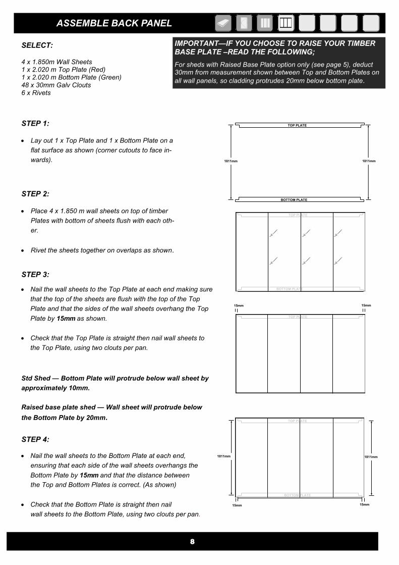
ASSEMBLE BACK PANEL
SELECT: 4 x 1.850m Wall Sheets 1 x 2.020 m Top Plate (Red) 1 x 2.020 m Bottom Plate (Green) 48 x 30mm Galv Clouts 6 x Rivets
STEP 1: Lay out 1 x Top Plate and 1 x Bottom Plate on a
flat surface as shown (corner cutouts to face in-
wards).
STEP 2: Place 4 x 1.850 m wall sheets on top of timber
Plates with bottom of sheets flush with each oth-
er.
Rivet the sheets together on overlaps as shown.
STEP 3:
Nail the wall sheets to the Top Plate at each end making sure
that the top of the sheets are flush with the top of the Top
Plate and that the sides of the wall sheets overhang the Top
Plate by 15mm as shown.
Check that the Top Plate is straight then nail wall sheets to
the Top Plate, using two clouts per pan.
STEP 4:
Nail the wall sheets to the Bottom Plate at each end,
ensuring that each side of the wall sheets overhangs the
Bottom Plate by 15mm and that the distance between
the Top and Bottom Plates is correct. (As shown)
Check that the Bottom Plate is straight then nail
wall sheets to the Bottom Plate, using two clouts per pan.
8
BOTTOM PLATE
1811mm 1811mm
TOP PLATE
1811mm
TOP PLATE
15mm 15mm
BOTTOM PLATE
TOP PLATE
1811mm
BOTTOM PLATE
15mm 15mm
TOP PLATE
Std Shed — Bottom Plate will protrude below wall sheet by
approximately 10mm.
Raised base plate shed — Wall sheet will protrude below
the Bottom Plate by 20mm.
IMPORTANT—IF YOU CHOOSE TO RAISE YOUR TIMBER BASE PLATE –READ THE FOLLOWING;
For sheds with Raised Base Plate option only (see page 5), deduct 30mm from measurement shown between Top and Bottom Plates on
all wall panels, so cladding protrudes 20mm below bottom plate.
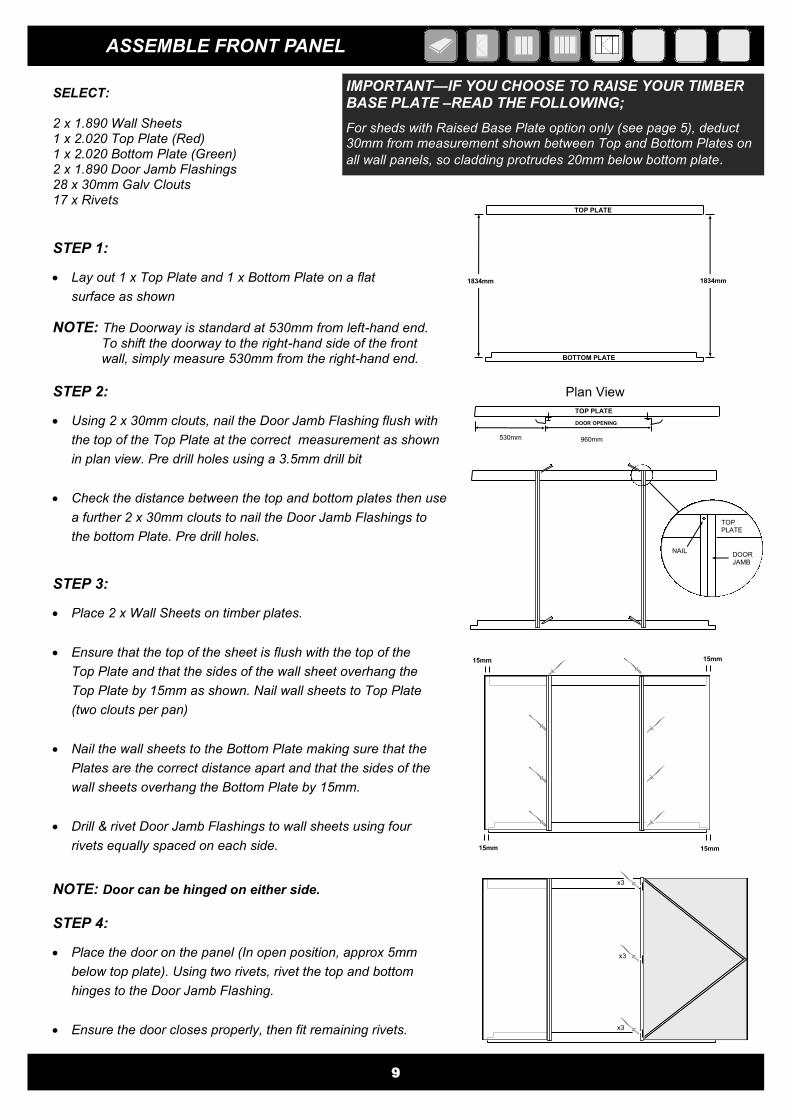
ASSEMBLE FRONT PANEL
SELECT: 2 x 1.890 Wall Sheets 1 x 2.020 Top Plate (Red) 1 x 2.020 Bottom Plate (Green) 2 x 1.890 Door Jamb Flashings 28 x 30mm Galv Clouts 17 x Rivets
BOTTOM PLATE
1834mm 1834mm
TOP PLATE
9
15mm 15mm
15mm 15mm
530mm 960mm
TOP PLATE
DOOR OPENING
STEP 1:
Lay out 1 x Top Plate and 1 x Bottom Plate on a flat
surface as shown
STEP 2:
Using 2 x 30mm clouts, nail the Door Jamb Flashing flush with
the top of the Top Plate at the correct measurement as shown
in plan view. Pre drill holes using a 3.5mm drill bit
Check the distance between the top and bottom plates then use
a further 2 x 30mm clouts to nail the Door Jamb Flashings to
the bottom Plate. Pre drill holes.
NOTE: Door can be hinged on either side.
STEP 4:
Place the door on the panel (In open position, approx 5mm
below top plate). Using two rivets, rivet the top and bottom
hinges to the Door Jamb Flashing.
Ensure the door closes properly, then fit remaining rivets.
STEP 3:
Place 2 x Wall Sheets on timber plates.
Ensure that the top of the sheet is flush with the top of the
Top Plate and that the sides of the wall sheet overhang the
Top Plate by 15mm as shown. Nail wall sheets to Top Plate
(two clouts per pan)
Nail the wall sheets to the Bottom Plate making sure that the
Plates are the correct distance apart and that the sides of the
wall sheets overhang the Bottom Plate by 15mm.
Drill & rivet Door Jamb Flashings to wall sheets using four
rivets equally spaced on each side.
NOTE: The Doorway is standard at 530mm from left-hand end. To shift the doorway to the right-hand side of the front wall, simply measure 530mm from the right-hand end.
TOP PLATE
DOOR JAMB
NAIL
Plan View
x3
x3
x3
IMPORTANT—IF YOU CHOOSE TO RAISE YOUR TIMBER BASE PLATE –READ THE FOLLOWING;
For sheds with Raised Base Plate option only (see page 5), deduct 30mm from measurement shown between Top and Bottom Plates on
all wall panels, so cladding protrudes 20mm below bottom plate.
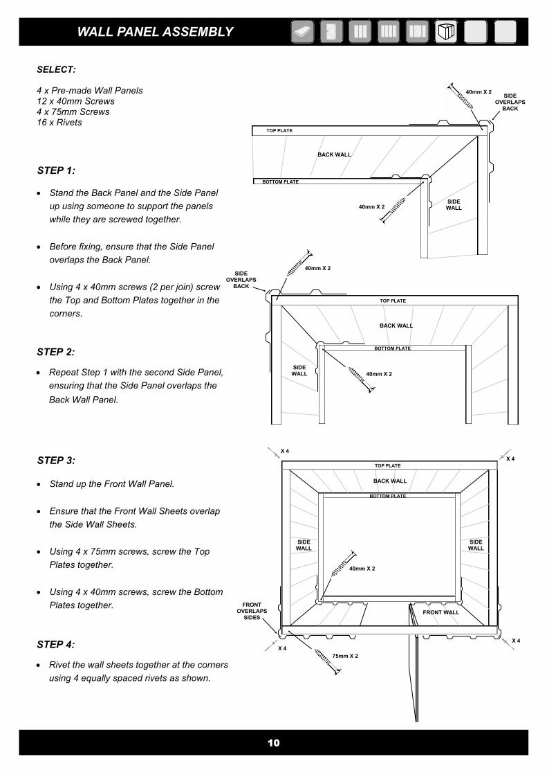
WALL PANEL ASSEMBLY
40mm X 2
40mm X 2
BACK WALL
SIDE WALL
SIDE OVERLAPS
BACK
SELECT: 4 x Pre-made Wall Panels 12 x 40mm Screws 4 x 75mm Screws 16 x Rivets
10
TOP PLATE
BOTTOM PLATE
40mm X 2
BACK WALL
SIDE WALL
SIDE OVERLAPS
BACK
40mm X 2
TOP PLATE
BOTTOM PLATE
FRONT OVERLAPS
SIDES
X 4
SIDE WALL
BACK WALL
SIDE WALL
FRONT WALL
X 4
X 4
X 4
TOP PLATE
BOTTOM PLATE
STEP 1:
Stand the Back Panel and the Side Panel
up using someone to support the panels
while they are screwed together.
Before fixing, ensure that the Side Panel
overlaps the Back Panel.
Using 4 x 40mm screws (2 per join) screw
the Top and Bottom Plates together in the
corners.
STEP 2:
Repeat Step 1 with the second Side Panel,
ensuring that the Side Panel overlaps the
Back Wall Panel.
STEP 3: Stand up the Front Wall Panel.
Ensure that the Front Wall Sheets overlap
the Side Wall Sheets.
Using 4 x 75mm screws, screw the Top
Plates together.
Using 4 x 40mm screws, screw the Bottom
Plates together.
STEP 4:
Rivet the wall sheets together at the corners
using 4 equally spaced rivets as shown.
75mm X 2
40mm X 2
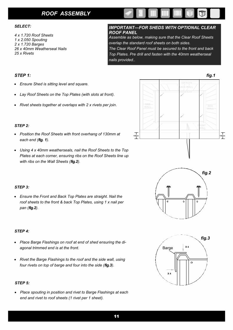
ROOF ASSEMBLY
SELECT: 4 x 1.720 Roof Sheets 1 x 2.050 Spouting 2 x 1.720 Barges 26 x 40mm Weatherseal Nails 25 x Rivets
STEP 1:
Ensure Shed is sitting level and square.
Lay Roof Sheets on the Top Plates (with slots at front).
Rivet sheets together at overlaps with 2 x rivets per join.
STEP 2:
Position the Roof Sheets with front overhang of 130mm at
each end (fig. 1).
Using 4 x 40mm weatherseals, nail the Roof Sheets to the Top
Plates at each corner, ensuring ribs on the Roof Sheets line up
with ribs on the Wall Sheets (fig.2).
STEP 3:
Ensure the Front and Back Top Plates are straight. Nail the
roof sheets to the front & back Top Plates, using 1 x nail per
pan (fig.2).
11
STEP 4:
Place Barge Flashings on roof at end of shed ensuring the di-
agonal trimmed end is at the front.
Rivet the Barge Flashings to the roof and the side wall, using
four rivets on top of barge and four into the side (fig.3).
fig.2
fig.3
X 4
X 4
Barge
IMPORTANT—FOR SHEDS WITH OPTIONAL CLEAR ROOF PANEL
Assemble as below, making sure that the Clear Roof Sheets
overlap the standard roof sheets on both sides.
The Clear Roof Panel must be secured to the front and back
Top Plates. Pre drill and fasten with the 40mm weatherseal
nails provided..
SIDE WALL
FRONT WALL
BACK WALL
SIDE WALL
TOP PLATE
BOTTOM PLATE
fig.1
130mm 130mm
STEP 5:
Place spouting in position and rivet to Barge Flashings at each
end and rivet to roof sheets (1 rivet per 1 sheet).
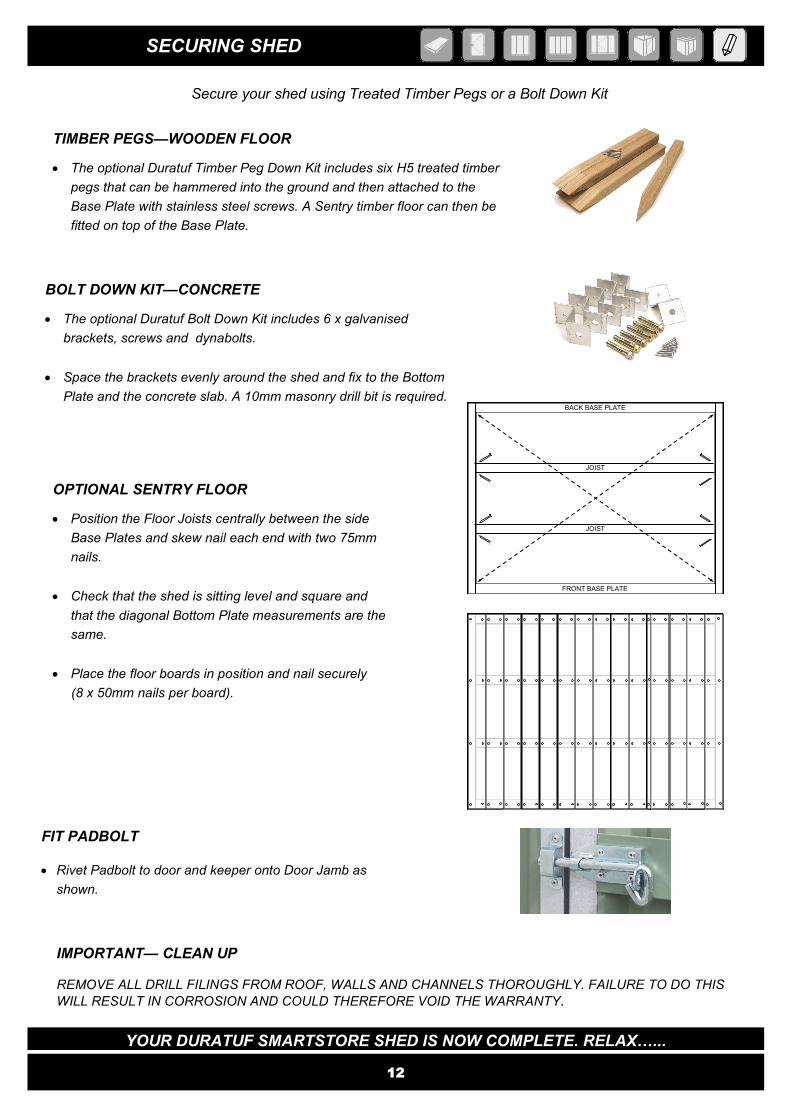
SECURING SHED
12
Secure your shed using Treated Timber Pegs or a Bolt Down Kit
TIMBER PEGS—WOODEN FLOOR
The optional Duratuf Timber Peg Down Kit includes six H5 treated timber
pegs that can be hammered into the ground and then attached to the
Base Plate with stainless steel screws. A Sentry timber floor can then be
fitted on top of the Base Plate.
BOLT DOWN KIT—CONCRETE
The optional Duratuf Bolt Down Kit includes 6 x galvanised
brackets, screws and dynabolts.
Space the brackets evenly around the shed and fix to the Bottom
Plate and the concrete slab. A 10mm masonry drill bit is required.
OPTIONAL SENTRY FLOOR
Position the Floor Joists centrally between the side
Base Plates and skew nail each end with two 75mm
nails.
Check that the shed is sitting level and square and
that the diagonal Bottom Plate measurements are the
same.
Place the floor boards in position and nail securely
(8 x 50mm nails per board).
IMPORTANT— CLEAN UP REMOVE ALL DRILL FILINGS FROM ROOF, WALLS AND CHANNELS THOROUGHLY. FAILURE TO DO THIS
WILL RESULT IN CORROSION AND COULD THEREFORE VOID THE WARRANTY.
FIT PADBOLT Rivet Padbolt to door and keeper onto Door Jamb as
shown.
YOUR DURATUF SMARTSTORE SHED IS NOW COMPLETE. RELAX…...
FRONT BASE PLATE
BACK BASE PLATE
JOIST
JOIST

Riverlea Group Ltd warrant that the cladding used in the manufacture of the Smartstore shed will not rust within 15 years from the date of purchase.
Any liability for product failure that may arise will be limited to repair or replacement of the defective product and will only apply for the benefit of the original purchaser. Riverlea Group Limited will not be liable for any consequential loss or damage, labour, or transport charges.
This warranty is conditional on:
Construction, installation and maintenance being carried out as specified in the Assembly Instruction Manual.
The shed being installed in modest inland corrosion zones or areas where the steel corrosion rate is less than 200g/m2
(as published by Branz).
Warranty certificate being returned to manufacturer within 21 days of purchase together with proof of purchase.
This warranty does not cover the following:
Fastenings and fixings.
Normal wear and tear, damage by impact or acts of God.
Situations where the shed has been used for storage of chemicals, manure or corrosion causing products. Unauthorized modification of the structure, including painting of the cladding.
Please visit http://www.riverleagroup.co.nz/warranty-garden-sheds to validate the Warranty on your shed. Click on the Warranty Registration Link and complete all details. If you are unable to access the computer, please phone us on 0800 438 274 and one of the customer services team will help you to activate the warranty on your garden shed.
Many thanks, from the Team at Riverlea Group.
15 YEAR WARRANTY
WARRANTY REGISTRATION