Embed Size (px)
Citation preview
Italian Technology of Broadcast
Reference Manual ATLAS 1000 AR144 Page 1 of 34
ATLAS 1000 AR 144
Manual for Systems and Procedures
Via Casale 3/A 20144 Milano Italy
Phone: (39) 02 90389417 Fax: (39) 02 23168389 E‐mail: [email protected]
WorldWide web: www.italab.it
ITALAB reserves the right to modify and change the information contained in this document without previous notice.
Ediz./Rev. Date Reason Approved by:
ATLAS1000‐AR144/00 01/01/2016 First Edition Micalizzi ‐ Scandelli
Italian Technology of Broadcast
Reference Manual ATLAS 1000 AR144 Page 2 of 34
Warranty ITALAB warranty covers the product’s materials and fabrication defects for a period of 2 years from the date of delivery. The standard warranty can be extended beyond this period. The conditions for such extensions are shown on the sales order per each purchased product. They are valid throughout the extension period of each product. During the warranty period, ITALAB takes responsibility for repair or substitution of the defected product. The warranty applies only if the product is returned to ITALAB after the assistance has been granted and only in case maintenance procedures are performed, as indicated on the manual. ITALAB retains the right of substitution of defective products or their components with new products or new revised parts. The warranty does not cover repair of products that have been damaged by mishandling or through improper use. Warranty does not cover the product if it has been manipulated. The warranty does not cover power Mosfets because there is already a constructor’s warranty and moving parts. NO OTHER WARRANTY APPLIES THE ITALAB WARRANTY DOES NOT COVER DAMAGE OR DEFECTS AS A CONSEQUENCE OF USE, OR IMPROPER USE OF THE PRODUCT (USE DIFFERENT FROM WHAT THE PRODUCT HAS BEEN DESIGNED FOR). THE WARRANTY DOES NOT COVER IMPROPER CONNECTION OF THE DEVICE TO OTHER DEVICES. If you think your device needs repair, please call ITALAB immediately and request customer support. It is important you contact ITALAB immediately as most problems can be quickly solved by telephone or by email. Please have the registration number of the product ready before you contact ITALAB and clearly describe the nature of the problem. Once you have recognized the malfunction and you are sure the product needs to be repaired, we will send you an electronic spreadsheet which needs filling out with name, address, telephone number, email and an accurate description of the problem. In the spreadsheet there will be an RMA number for the delivery of the unit with a pre‐paid delivery to the lab at the indicated location. The product must be sent in its original packaging or within an adequate container that will protect the item. ITALAB will not be held responsible for damage which has taken place during transport. Please verify that the RMA number is clearly indicated on the packaging. Our standard conditions for repairs are of 5 working days from product reception. In case we needed to order additional components for your repair and this were to take more than 5 working days, our technical service will contact you and inform you about the variation on delivery lead time. In order to repair a product out of its warranty time, we will have to follow the same procedure described above but you will have to tick the box “not under warranty”. The warranty is valid only if the adequate maintenance procedures have been respected as described on the manual. Damage caused by incorrect use of the product will NOT be covered by the warranty.
Warranty Service The ATLAS 1000 AR144 is a highly reliable device. Nevertheless, as it happens for all advice active 24 hours over a number of years, some malfunctions may take place. Repair of the modules within the amplifier is very difficult on site, it is recommended you contact our client assistance service:
ITALAB Via Casale 3/A 20144 Milan Italy Phone: (39) 02 90389417 ‐ Fax: (39) 02 23168389 Mail : [email protected]
Italian Technology of Broadcast
Reference Manual ATLAS 1000 AR144 Page 3 of 34
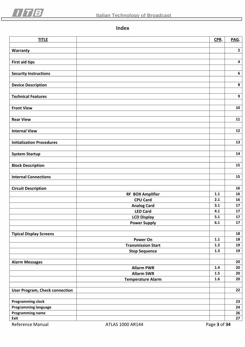
Index
TITLE CPR. PAG.
Warranty 2 First aid tips 4 Security Instructions 6 Device Description 8 Technical Features 9 Front View 10 Rear View 11 Internal View 12 Initialization Procedures 13 System Startup 14 Block Description 15 Internal Connections 15 Circuit Description 16 RF BOX Amplifier 1.1 16 CPU Card 2.1 16 Analog Card 3.1 17 LED Card 4.1 17 LCD Display 5.1 17 Power Supply 6.1 17 Tipical Display Screens 18 Power On 1.1 18 Transmission Start 1.2 19 Stop Sequence 1.3 19 Alarm Messages 20 Allarm PWR 1.4 20 Allarm SWR 1.5 20 Temperature Alarm 1.6 20 User Program, Check connection 22 Programming clock 23Programming language 24Programming name 26Exit 27
Italian Technology of Broadcast
Reference Manual ATLAS 1000 AR144 Page 4 of 34
FIRST AID TIPS
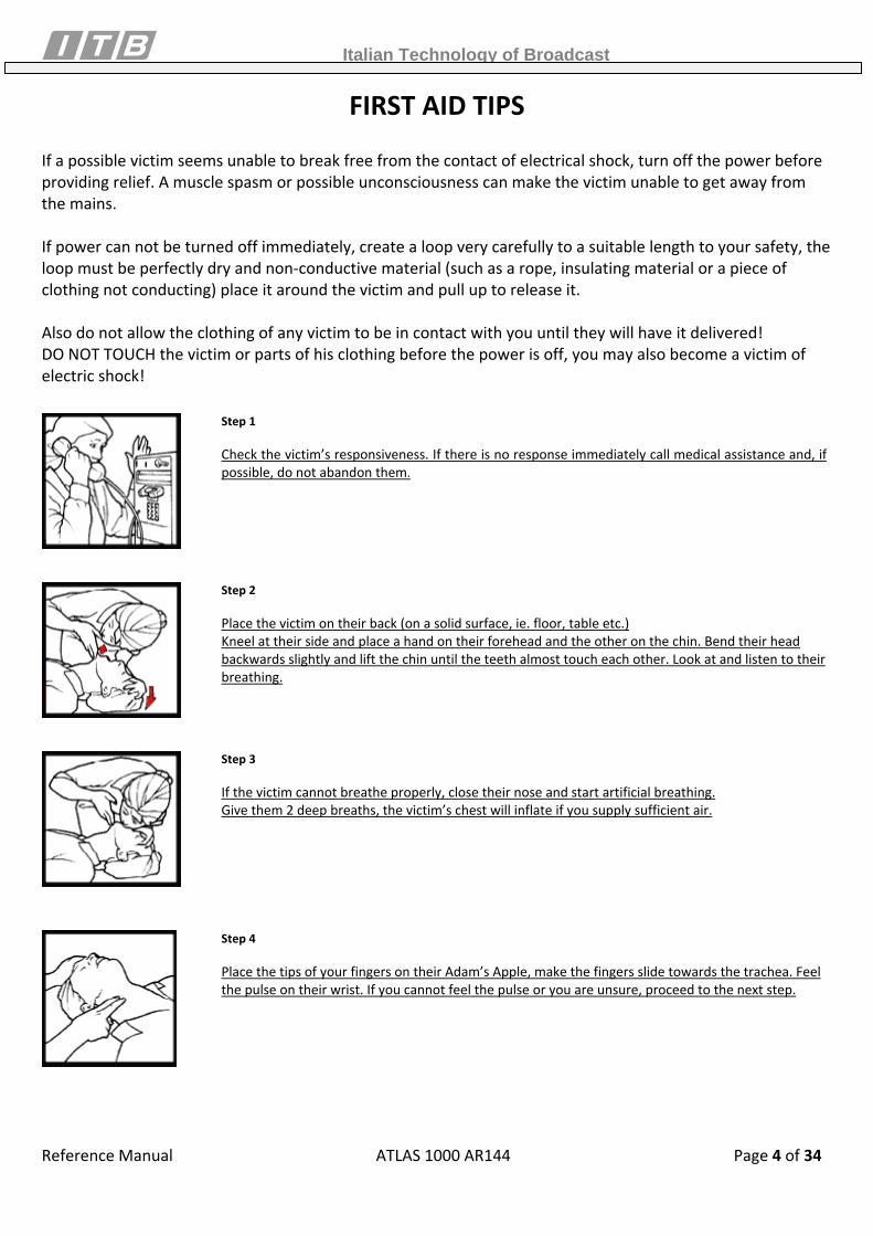
If a possible victim seems unable to break free from the contact of electrical shock, turn off the power before providing relief. A muscle spasm or possible unconsciousness can make the victim unable to get away from the mains. If power can not be turned off immediately, create a loop very carefully to a suitable length to your safety, the loop must be perfectly dry and non‐conductive material (such as a rope, insulating material or a piece of clothing not conducting) place it around the victim and pull up to release it. Also do not allow the clothing of any victim to be in contact with you until they will have it delivered! DO NOT TOUCH the victim or parts of his clothing before the power is off, you may also become a victim of electric shock!
Step 1 Check the victim’s responsiveness. If there is no response immediately call medical assistance and, if possible, do not abandon them.
Step 2 Place the victim on their back (on a solid surface, ie. floor, table etc.) Kneel at their side and place a hand on their forehead and the other on the chin. Bend their head backwards slightly and lift the chin until the teeth almost touch each other. Look at and listen to their breathing.
Step 3 If the victim cannot breathe properly, close their nose and start artificial breathing. Give them 2 deep breaths, the victim’s chest will inflate if you supply sufficient air.
Step 4 Place the tips of your fingers on their Adam’s Apple, make the fingers slide towards the trachea. Feel the pulse on their wrist. If you cannot feel the pulse or you are unsure, proceed to the next step.
Italian Technology of Broadcast
Reference Manual ATLAS 1000 AR144 Page 5 of 34
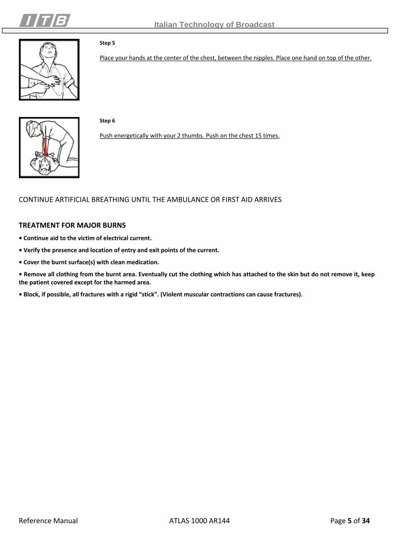
Step 5 Place your hands at the center of the chest, between the nipples. Place one hand on top of the other.
Step 6 Push energetically with your 2 thumbs. Push on the chest 15 times.
CONTINUE ARTIFICIAL BREATHING UNTIL THE AMBULANCE OR FIRST AID ARRIVES
TREATMENT FOR MAJOR BURNS • Continue aid to the victim of electrical current.
• Verify the presence and location of entry and exit points of the current.
• Cover the burnt surface(s) with clean medication.
• Remove all clothing from the burnt area. Eventually cut the clothing which has attached to the skin but do not remove it, keep the patient covered except for the harmed area.
• Block, if possible, all fractures with a rigid “stick”. (Violent muscular contractions can cause fractures).
Italian Technology of Broadcast
Reference Manual ATLAS 1000 AR144 Page 6 of 34
Safety Instructions
To optimize the user safety and to guarantee correct functioning of the device, all our instructions are contained in the present manual and must be very carefully followed. OPERATIONAL CONDITIONS The device has been designed to work:
• With power voltage of 240 Volt +/‐ 30 Volt alternating current at 50÷60 Hz • Room temperature must be between 0 and 40 ° C. • Maximum height of 3500 slm.
ATTENTION: there are dangerous voltages within the device. PROTECTION GROUNDING To protect people from the risk of electrocution, the amplifier frame must be connected to an electric ground through the network power cable. The third cable (green yellow) must be connected to an electric ground (safety ground) within the power socket. Any interruption of the ground conductor will cause a potential electrocution danger which could cause personal lesions. If the amplifier is powered by other devices, you must verify the frame has been connected to a separate security ground. DO NOT USE IN EXPLOSIVE ENVIRONMENTS Running ATLAS 1000 AR144 in presence of flammable gasses or vapours can be the source of danger for people near. DO NOT TRY TO REPAIR ATLAS 1000 AR144 Maintenance, repair and substitution of internal parts must be performed only by qualified ITB personnel. FUSES In case the fuses break, after having removed the cause of the problem, please substitute them with the same kind. They must have the same current, voltage and intervention time features. Exit Connector The RF exit “N” connector carries an RF signal which is dangerously high and can cause shock and burns. Do not use the amplifier without having correctly connected the connector to a load of adequate proportions or to the antenna. Electrostatic Charges (ESD) An unexpected electric electrostatic charge can destroy devices sensitive to static electricity such as micro circuits. To avoid this, correct grounding techniques must be used. Please use standard procedures to avoid these events.
THE REMOVAL OF ANY PANEL HAS TO BE DONE BY AUTHORIZED AND QUALIFIED PERSONNEL
Italian Technology of Broadcast
Reference Manual ATLAS 1000 AR144 Page 7 of 34
General Safety Rules
• The device must be used following described norms. • To perform the electrical installation within interior environments it will be necessary to follow conformity norms aligned
with the current safety guidelines. • Ensure there are no cables in areas where people transit or work, especially cables which power the devices. • Do not use a network connection shared with other users to power the device. Do not use an extension cable. • Only use the power cable supplied or, in case the length is not sufficient, prepare one with the same accessories and
features as those of the original one. • The amplifier must be totally disconnected from the power network only when the power cable is removed. For this
reason, the power cable must be easy to access. • Do not install the device near sources of heat or in humid areas. Ensure the device has adequate ventilation. • The amplifier must not be near water or objects containing water. • The amplifier must be located in such manner as to avoid interference with ventilation necessary to cool it down. For
example, the device must not be inserted within enclosed furniture such as a bookshelf or a cupboard. This could interfere with air expulsion flow through the openings.
• All cable connectors must be well screwed and fixed to the unit. • The device has been designed to be used in a horizontal position. • When the device shows visible damage or has not been used for a while, or it has not been stored as described, it will no
longer be safe to operate. • In case there were technical problems or in case of any doubt, please immediately contact our technicians in order to avoid
possible abnormalities. • In case of visible damage or malfunctioning of ATLAS 1000 AR144, it is advised to turn the power off. • The maintenance and repair can be made only by authorized ITALAB staff. • Before removing the ATLAS 1000 AR144 cover, please turn off the power switch. This can be found on the rear of the
device. The power cable must be removed from the electric socket. Environmental Conditions To optimize performance of the apparatus, in terms of output power, life‐span etc, the following environmental parameters must be followed:
• Room temperature must be between 0 and 40°C • Humidity must be below 80% and must not create condensation
The equipment can also work at different parameters from the ones specified above but ITALAB cannot guarantee the uninterrupted service. If the device reaches internal temperatures above 50° , it will automatically go in standby mode. It is advised to regulate the conditions of the room which will host the device. What is necessary is a good ventilation in order to maintain the temperature lower than or equal to 30 ‐ 35°C. If the equipment is placed within a Rack cupboard, please ensure that the rear is not closed. This will allow expulsion of hot air from the fans within the amplifier. If the device stays closed, please provide an adequate extraction fan system.
Italian Technology of Broadcast
Reference Manual ATLAS 1000 AR144 Page 8 of 34
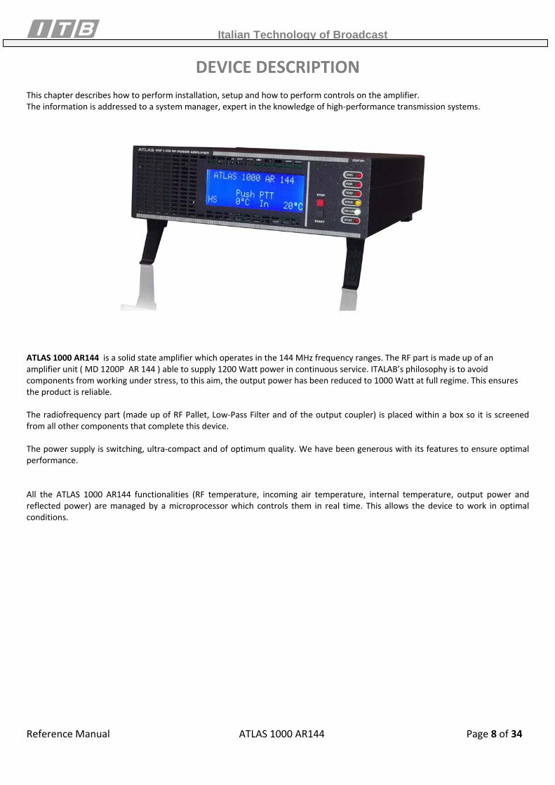
DEVICE DESCRIPTION
This chapter describes how to perform installation, setup and how to perform controls on the amplifier. The information is addressed to a system manager, expert in the knowledge of high‐performance transmission systems.
ATLAS 1000 AR144 is a solid state amplifier which operates in the 144 MHz frequency ranges. The RF part is made up of an amplifier unit ( MD 1200P AR 144 ) able to supply 1200 Watt power in continuous service. ITALAB’s philosophy is to avoid components from working under stress, to this aim, the output power has been reduced to 1000 Watt at full regime. This ensures the product is reliable. The radiofrequency part (made up of RF Pallet, Low‐Pass Filter and of the output coupler) is placed within a box so it is screened from all other components that complete this device. The power supply is switching, ultra‐compact and of optimum quality. We have been generous with its features to ensure optimal performance. All the ATLAS 1000 AR144 functionalities (RF temperature, incoming air temperature, internal temperature, output power and reflected power) are managed by a microprocessor which controls them in real time. This allows the device to work in optimal conditions.
Italian Technology of Broadcast
Reference Manual ATLAS 1000 AR144 Page 9 of 34
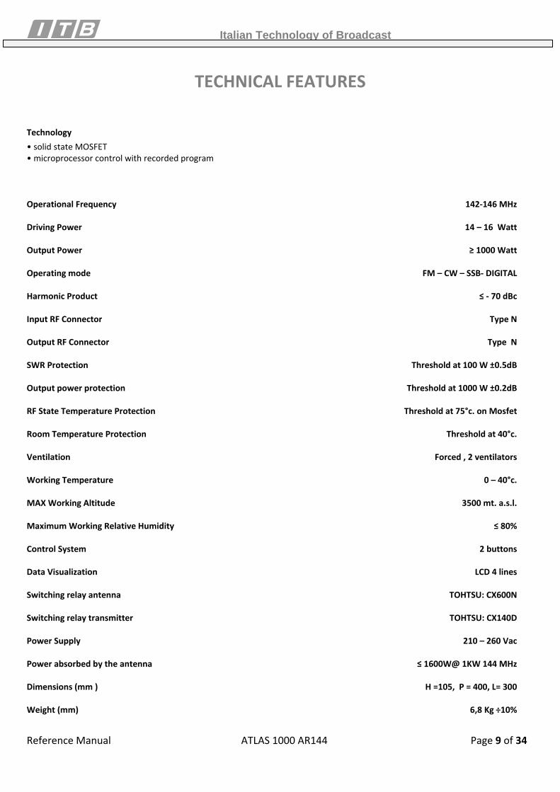
TECHNICAL FEATURES
Technology • solid state MOSFET • microprocessor control with recorded program Operational Frequency 142‐146 MHz Driving Power 14 – 16 Watt Output Power ≥ 1000 Watt Operating mode FM – CW – SSB‐ DIGITAL Harmonic Product ≤ ‐ 70 dBc Input RF Connector Type N Output RF Connector Type N SWR Protection Threshold at 100 W ±0.5dB Output power protection Threshold at 1000 W ±0.2dB RF State Temperature Protection Threshold at 75°c. on Mosfet Room Temperature Protection Threshold at 40°c. Ventilation Forced , 2 ventilators Working Temperature 0 – 40°c. MAX Working Altitude 3500 mt. a.s.l. Maximum Working Relative Humidity ≤ 80% Control System 2 buttons Data Visualization LCD 4 lines Switching relay antenna TOHTSU: CX600N Switching relay transmitter TOHTSU: CX140D Power Supply 210 – 260 Vac Power absorbed by the antenna ≤ 1600W@ 1KW 144 MHz Dimensions (mm ) H =105, P = 400, L= 300 Weight (mm) 6,8 Kg ÷10%

Italian Technology of Broadcast
Reference Manual ATLAS 1000 AR144 Page 10 of 34
FRONT PANEL
1
2 3 4
5
78
910
6
1. GRID Ventilation grid for RF Pallet 2. DISPLAY Visualization Display for device functions 3. STOP BUTTON STOP Button 4. START BUTTON START Button 5. LED SWR Alarm LED for Reflected Power 6. LED PWR Alarm LED for Direct Power 7. LED TEMP Alarm LED for overheating 8. LED ENAB ENABLE LED 9. LED ON AIR Broadcast Transmission LED 10. LED ST.BY Stand‐By LED
FUNCTIONS DESCRIPTION:
SWR LED: Flashing: indicates it is limiting the output RF power in order to reduce the reflected one. ON Constantly: indicates reflected power is more than 12% of the device’s rated power.
PWR LED: Flashing: indicates the device is limiting the output power to maintain the nominal value. ON Constantly: indicates the output power value is higher than the nominal one.
TEMP LED: ON Constantly: indicates the internal temperature of the device or of the pallets is higher than the
device’s parameters.
ENABLE LED: ON Constantly: indicates the device has removed the pallet enabling voltage.
ON AIR LED: Flashing: indicates the device is in transmission but does not detect the output power. ON Constantly: indicates the device is detecting the output power.
STAND BY LED: ON: indicates the device is in Stand‐By.
STOP BUTTON: By pressing the button, the device will go in stand‐by mode and the pallet will remove auxiliary output power from the device.
Italian Technology of Broadcast
Reference Manual ATLAS 1000 AR144 Page 11 of 34
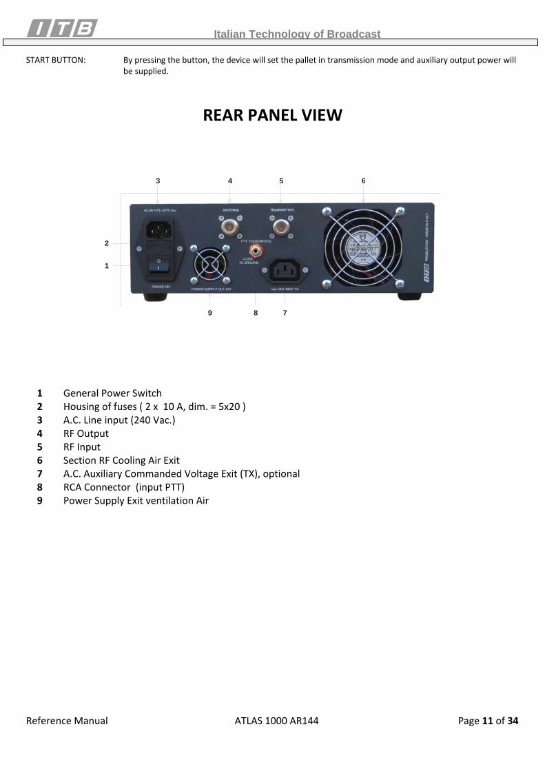
START BUTTON: By pressing the button, the device will set the pallet in transmission mode and auxiliary output power will be supplied.
REAR PANEL VIEW
1
2
3 4 5
8 7
6
9
1 General Power Switch 2 Housing of fuses ( 2 x 10 A, dim. = 5x20 ) 3 A.C. Line input (240 Vac.) 4 RF Output 5 RF Input 6 Section RF Cooling Air Exit 7 A.C. Auxiliary Commanded Voltage Exit (TX), optional 8 RCA Connector (input PTT) 9 Power Supply Exit ventilation Air
Italian Technology of Broadcast
Reference Manual ATLAS 1000 AR144 Page 12 of 34
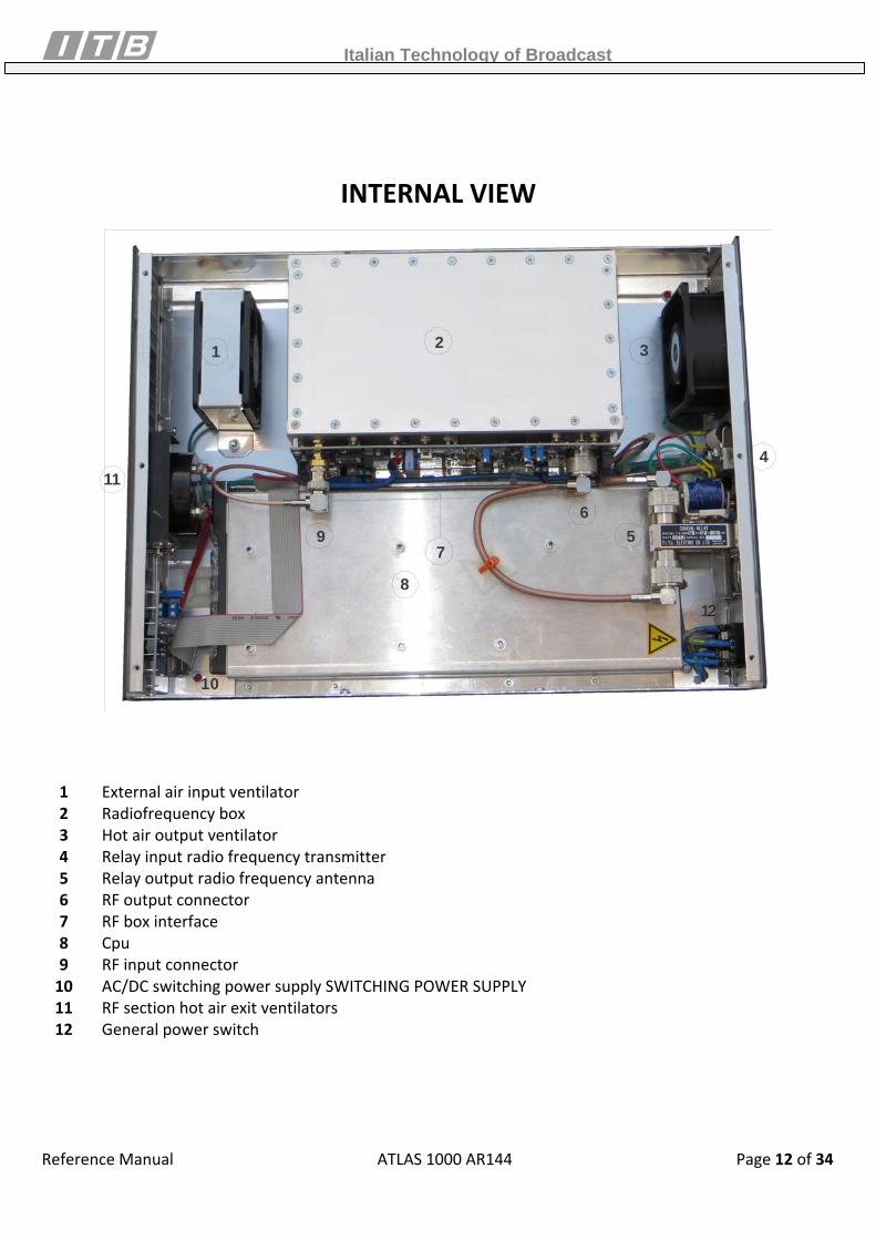
INTERNAL VIEW
21 3
1
9
11
10
7
4
65
82
1 External air input ventilator 2 Radiofrequency box 3 Hot air output ventilator 4 Relay input radio frequency transmitter 5 Relay output radio frequency antenna 6 RF output connector 7 RF box interface 8 Cpu 9 RF input connector 10 AC/DC switching power supply SWITCHING POWER SUPPLY 11 RF section hot air exit ventilators 12 General power switch

Italian Technology of Broadcast
Reference Manual ATLAS 1000 AR144 Page 13 of 34
STARTUP INSTALLATION PROCEDURE
If you require assistance or have any questions regarding the installation, ITALAB technical staff will be at your service to solve any problems. Please do not perform modifications which could damage the product. Before installing the amplifier, verify that the room containing it conforms to the following guidelines:
• There should not be excessive dust • There should not be deposits of corrosive chemical products such as chlorine, sulphur etc.. • Sources of heat (radiators, hot air ventilation etc.) should be at least 2 meters away; • Room temperature must be between 0 and +40 ° with relative humidity not higher than 90% without condensation
After having removed the amplifier from its packaging, verify that this has not undergone damage during transport.
Electrical Connections • The connection with primary power supply of 230 Vac must be performed with the power supply cable which has been
provided with the amplifier or with a cable with 3 conductors and with minimal conductor section of 2.5 square millimetres.
• For safety and good practice reasons, have a socket with a dedicated 2.5mm section cable which is directly derived from the primary panel with an adequate magneto‐thermic switch.
• Check that the ON / OFF switch on the rear panel on the amplifier is OFF. • Connect the power supply cable in the dedicated clamps at the rear of the amplifier respecting the specified polarities
shown in the rear view image. • Insert the other network power supply cable end to the socket with the correct connector. • Connect the exciter network power supply cable (supplied in the package) to the auxiliary socket on the rear of the
amplifier panel. This socket will be powered only when the amplifier is ready to function. • The maximum detectable current from the auxiliary socket is of 1.5 A & 230 Volts.
RF Connections
• Connect the antenna coaxial cable (with 50 Ω impedance) to the RF output N connector on the rear of the amplifier panel. • Connect the exciter RF output to the amplifier RF input with a coaxial cable with 50 Ω impedance.
Final Control before Start‐up Procedure Before you power the amplifier, verify once again the following safety measures:
The amplifier must have a ground connection The 230 Vac power supply and its protections must be properly connected. The power supply cable between the exciter and the amplifier must be connected correctly. The antenna cable must be connected and fixed properly. The RF connection cable between the exciter and the amplifier must be connected. Please ensure Power reaching the amplifier is not higher than 2 Watts. An excessively high input power or high initial peaks will damage the device.
Italian Technology of Broadcast
Reference Manual ATLAS 1000 AR144 Page 14 of 34
SYSTEM STARTUP
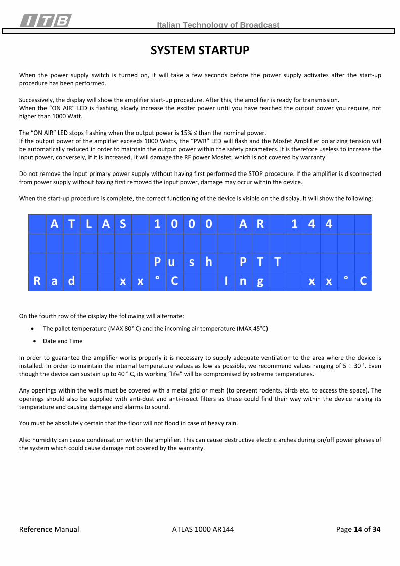
When the power supply switch is turned on, it will take a few seconds before the power supply activates after the start‐up procedure has been performed. Successively, the display will show the amplifier start‐up procedure. After this, the amplifier is ready for transmission. When the “ON AIR” LED is flashing, slowly increase the exciter power until you have reached the output power you require, not higher than 1000 Watt. The “ON AIR” LED stops flashing when the output power is 15% ≤ than the nominal power. If the output power of the amplifier exceeds 1000 Watts, the “PWR” LED will flash and the Mosfet Amplifier polarizing tension will be automatically reduced in order to maintain the output power within the safety parameters. It is therefore useless to increase the input power, conversely, if it is increased, it will damage the RF power Mosfet, which is not covered by warranty. Do not remove the input primary power supply without having first performed the STOP procedure. If the amplifier is disconnected from power supply without having first removed the input power, damage may occur within the device. When the start‐up procedure is complete, the correct functioning of the device is visible on the display. It will show the following:
A T L A S 1 0 0 0 A R 1 4 4 P u s h P T T R a d x x ° C I n g x x ° C
On the fourth row of the display the following will alternate:
• The pallet temperature (MAX 80° C) and the incoming air temperature (MAX 45°C)
• Date and Time In order to guarantee the amplifier works properly it is necessary to supply adequate ventilation to the area where the device is installed. In order to maintain the internal temperature values as low as possible, we recommend values ranging of 5 ÷ 30 °. Even though the device can sustain up to 40 ° C, its working “life” will be compromised by extreme temperatures. Any openings within the walls must be covered with a metal grid or mesh (to prevent rodents, birds etc. to access the space). The openings should also be supplied with anti‐dust and anti‐insect filters as these could find their way within the device raising its temperature and causing damage and alarms to sound. You must be absolutely certain that the floor will not flood in case of heavy rain. Also humidity can cause condensation within the amplifier. This can cause destructive electric arches during on/off power phases of the system which could cause damage not covered by the warranty.
Italian Technology of Broadcast
Reference Manual ATLAS 1000 AR144 Page 15 of 34
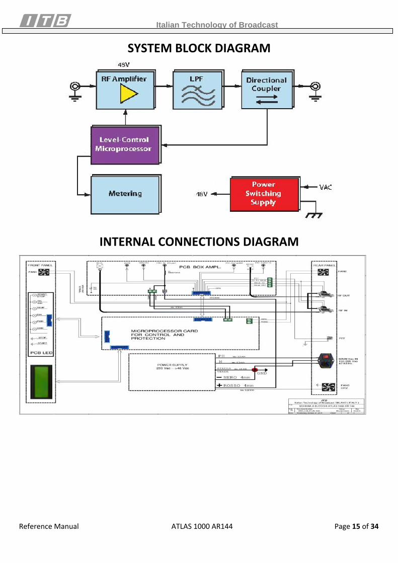
SYSTEM BLOCK DIAGRAM
INTERNAL CONNECTIONS DIAGRAM
Italian Technology of Broadcast
Reference Manual ATLAS 1000 AR144 Page 16 of 34
CIRCUIT DESCRIPTION
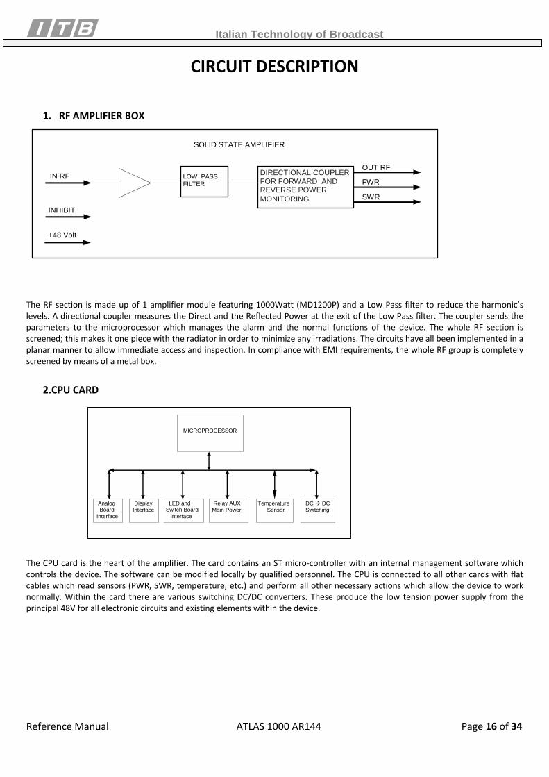
1. RF AMPLIFIER BOX
FWR
SWR
IN RF LOW PASS FILTER
OUT RF
SOLID STATE AMPLIFIER
DIRECTIONAL COUPLER FOR FORWARD AND REVERSE POWER MONITORING
INHIBIT
+48 Volt
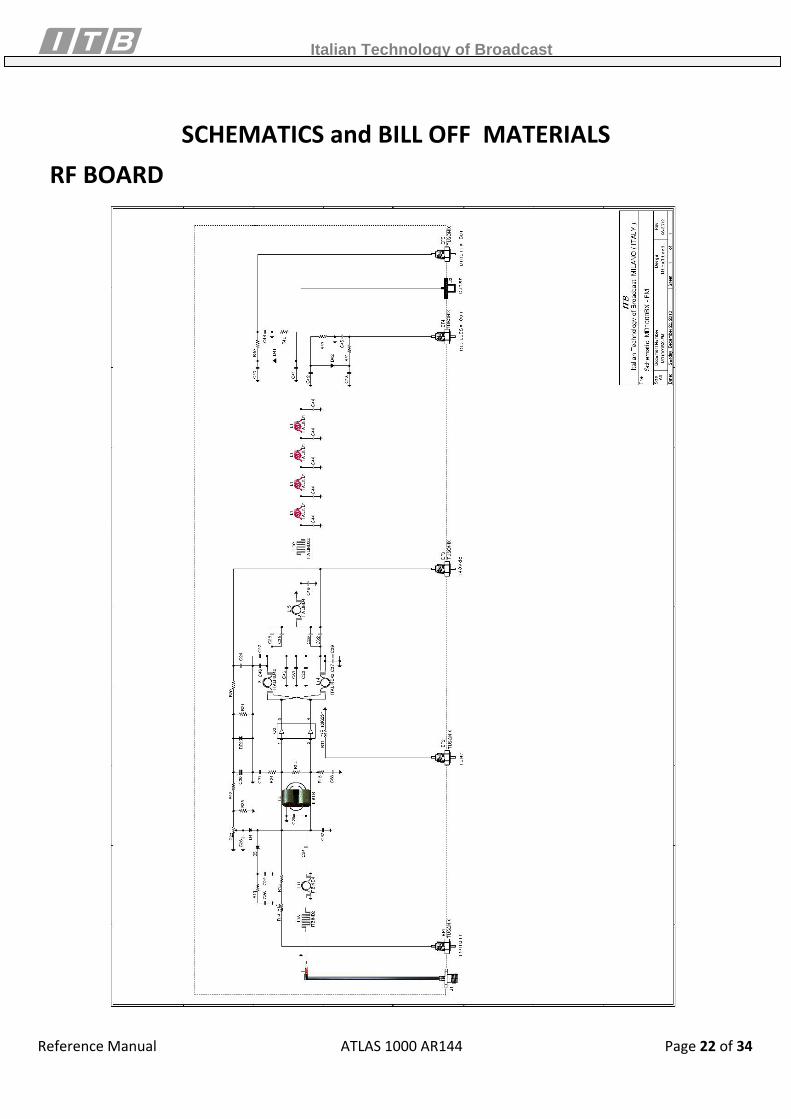
The RF section is made up of 1 amplifier module featuring 1000Watt (MD1200P) and a Low Pass filter to reduce the harmonic’s levels. A directional coupler measures the Direct and the Reflected Power at the exit of the Low Pass filter. The coupler sends the parameters to the microprocessor which manages the alarm and the normal functions of the device. The whole RF section is screened; this makes it one piece with the radiator in order to minimize any irradiations. The circuits have all been implemented in a planar manner to allow immediate access and inspection. In compliance with EMI requirements, the whole RF group is completely screened by means of a metal box.
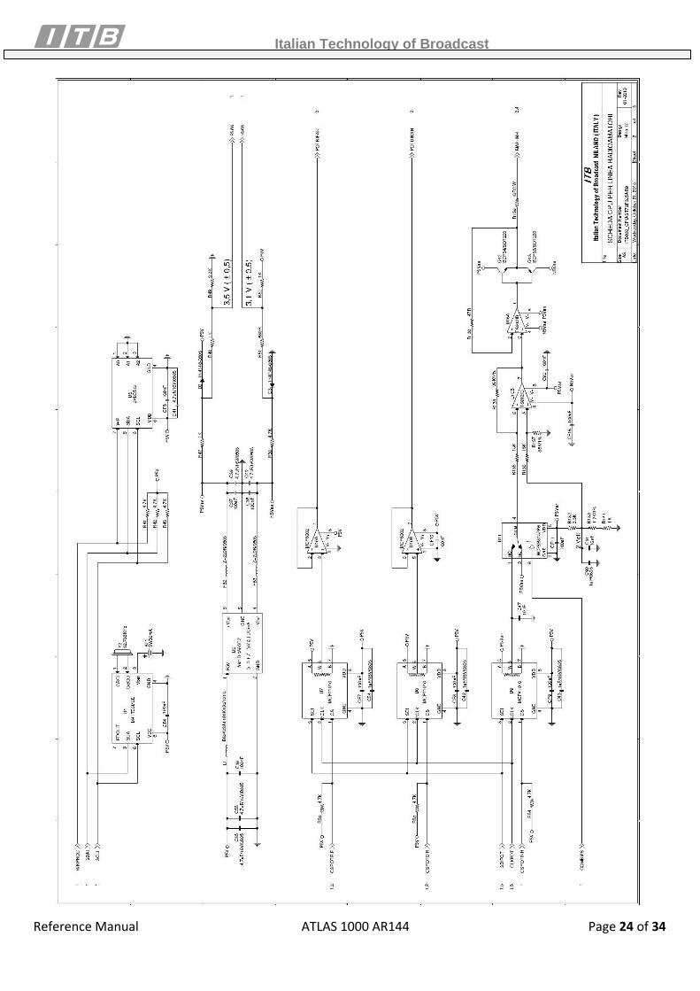
2.CPU CARD
MICROPROCESSOR
Analog Board Interface
Display Interface
LED and Switch Board Interface
Relay AUX Main Power
Temperature Sensor
DC DC Switching
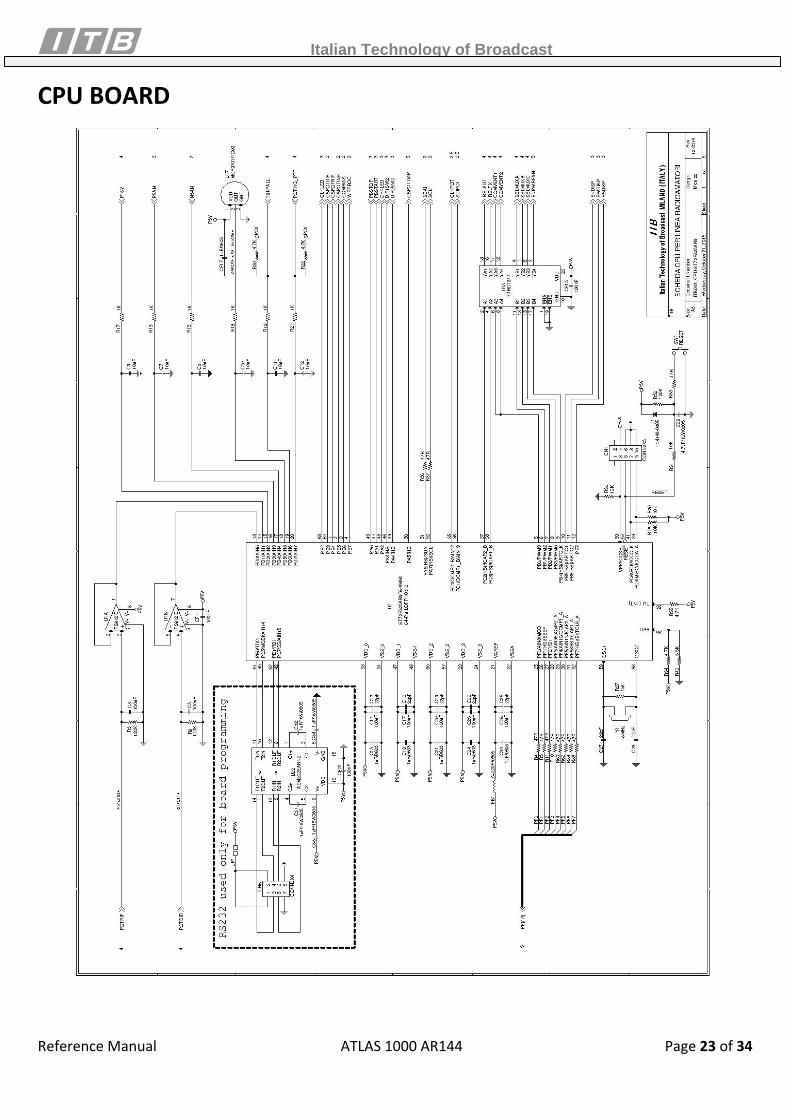
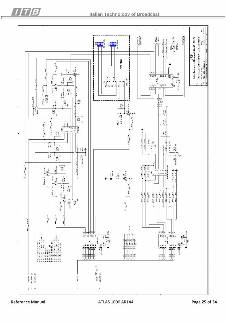
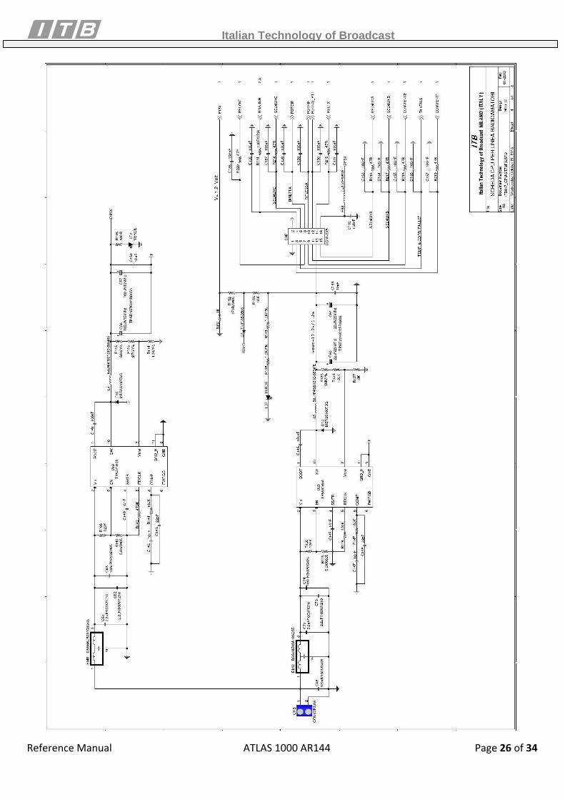
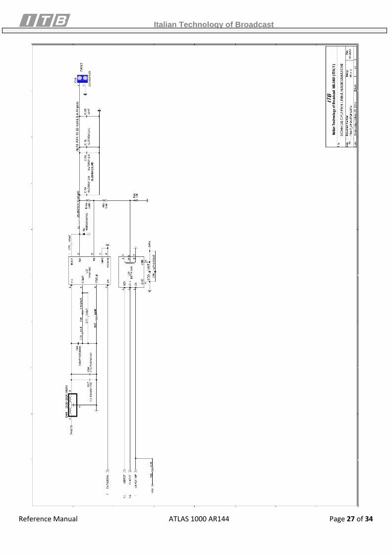
The CPU card is the heart of the amplifier. The card contains an ST micro‐controller with an internal management software which controls the device. The software can be modified locally by qualified personnel. The CPU is connected to all other cards with flat cables which read sensors (PWR, SWR, temperature, etc.) and perform all other necessary actions which allow the device to work normally. Within the card there are various switching DC/DC converters. These produce the low tension power supply from the principal 48V for all electronic circuits and existing elements within the device.
Italian Technology of Broadcast
Reference Manual ATLAS 1000 AR144 Page 17 of 34
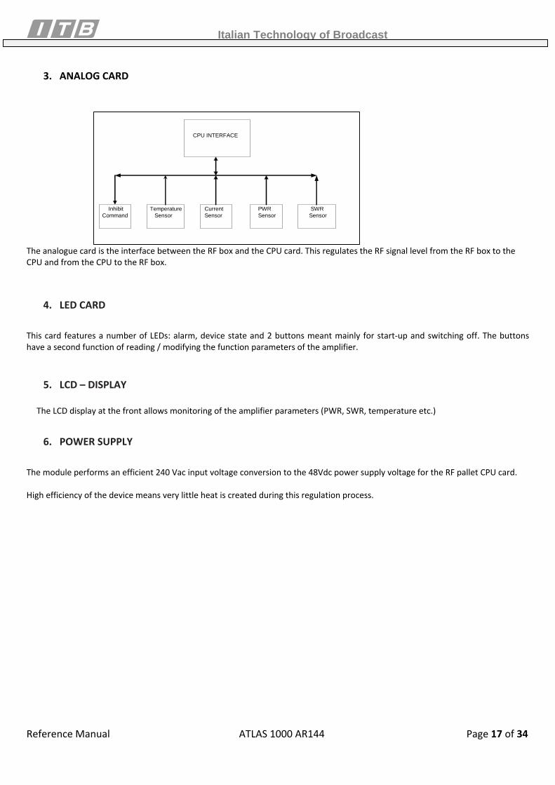
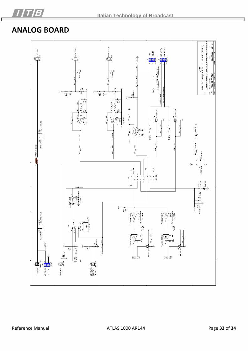
3. ANALOG CARD
CPU INTERFACE
Inhibit Command
Current Sensor
Temperature Sensor
PWR Sensor
SWR Sensor
The analogue card is the interface between the RF box and the CPU card. This regulates the RF signal level from the RF box to the CPU and from the CPU to the RF box.
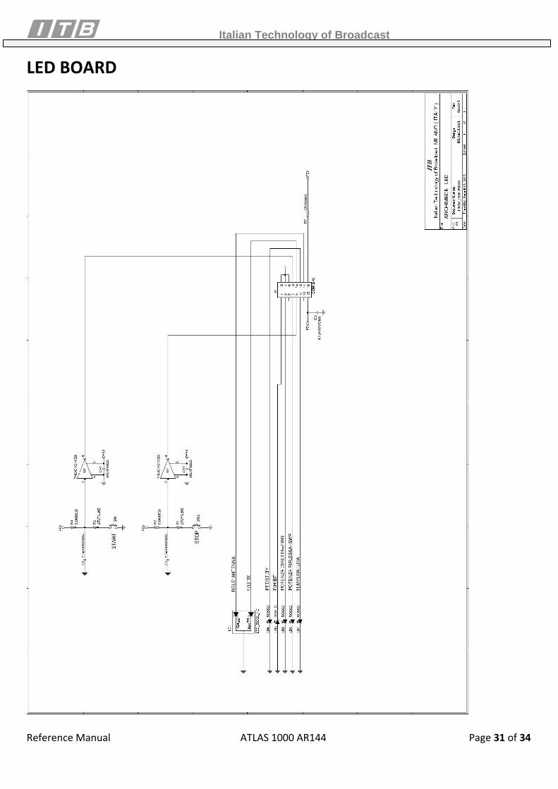
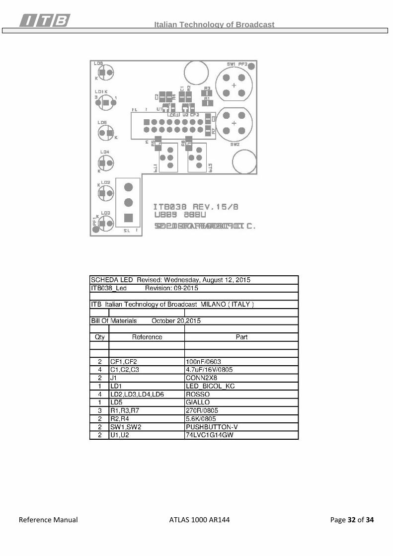
4. LED CARD
This card features a number of LEDs: alarm, device state and 2 buttons meant mainly for start‐up and switching off. The buttons have a second function of reading / modifying the function parameters of the amplifier.
5. LCD – DISPLAY
The LCD display at the front allows monitoring of the amplifier parameters (PWR, SWR, temperature etc.)
6. POWER SUPPLY
The module performs an efficient 240 Vac input voltage conversion to the 48Vdc power supply voltage for the RF pallet CPU card. High efficiency of the device means very little heat is created during this regulation process.
Italian Technology of Broadcast
Reference Manual ATLAS 1000 AR144 Page 18 of 34
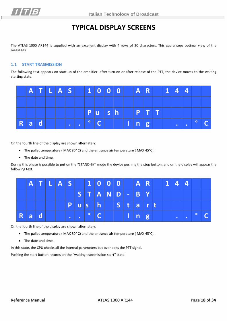
TYPICAL DISPLAY SCREENS The ATLAS 1000 AR144 is supplied with an excellent display with 4 rows of 20 characters. This guarantees optimal view of the messages.
1.1 START TRASMISSION The following text appears on start‐up of the amplifier after turn on or after release of the PTT, the device moves to the waiting starting state.
A T L A S 1 0 0 0 A R 1 4 4 P u s h P T T R a d . . ° C I n g . . ° C
On the fourth line of the display are shown alternately:
• The pallet temperature ( MAX 80° C) and the entrance air temperature ( MAX 45°C).
• The date and time.
During this phase is possible to put on the “STAND‐BY” mode the device pushing the stop button, and on the display will appear the following text.
A T L A S 1 0 0 0 A R 1 4 4 S T A N D ‐ B Y P u s h S t a r t R a d . . ° C I n g . . ° C
On the fourth line of the display are shown alternately:
• The pallet temperature ( MAX 80° C) and the entrance air temperature ( MAX 45°C).
• The date and time.
In this state, the CPU checks all the internal parameters but overlooks the PTT signal.
Pushing the start button returns on the “waiting transmission start” state.
Italian Technology of Broadcast
Reference Manual ATLAS 1000 AR144 Page 19 of 34
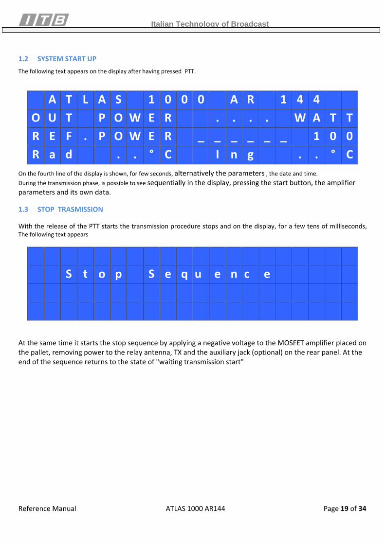
1.2 SYSTEM START UP The following text appears on the display after having pressed PTT.
A T L A S 1 0 0 0 A R 1 4 4 O U T P O W E R . . . . W A T TR E F . P O W E R _ _ _ _ _ _ 1 0 0R a d . . ° C I n g . . ° C
On the fourth line of the display is shown, for few seconds, alternatively the parameters , the date and time. During the transmission phase, is possible to see sequentially in the display, pressing the start button, the amplifier parameters and its own data.
1.3 STOP TRASMISSION
With the release of the PTT starts the transmission procedure stops and on the display, for a few tens of milliseconds, The following text appears
At the same time it starts the stop sequence by applying a negative voltage to the MOSFET amplifier placed on the pallet, removing power to the relay antenna, TX and the auxiliary jack (optional) on the rear panel. At the end of the sequence returns to the state of "waiting transmission start"
S t o p S e q u e n c e
Italian Technology of Broadcast
Reference Manual ATLAS 1000 AR144 Page 20 of 34
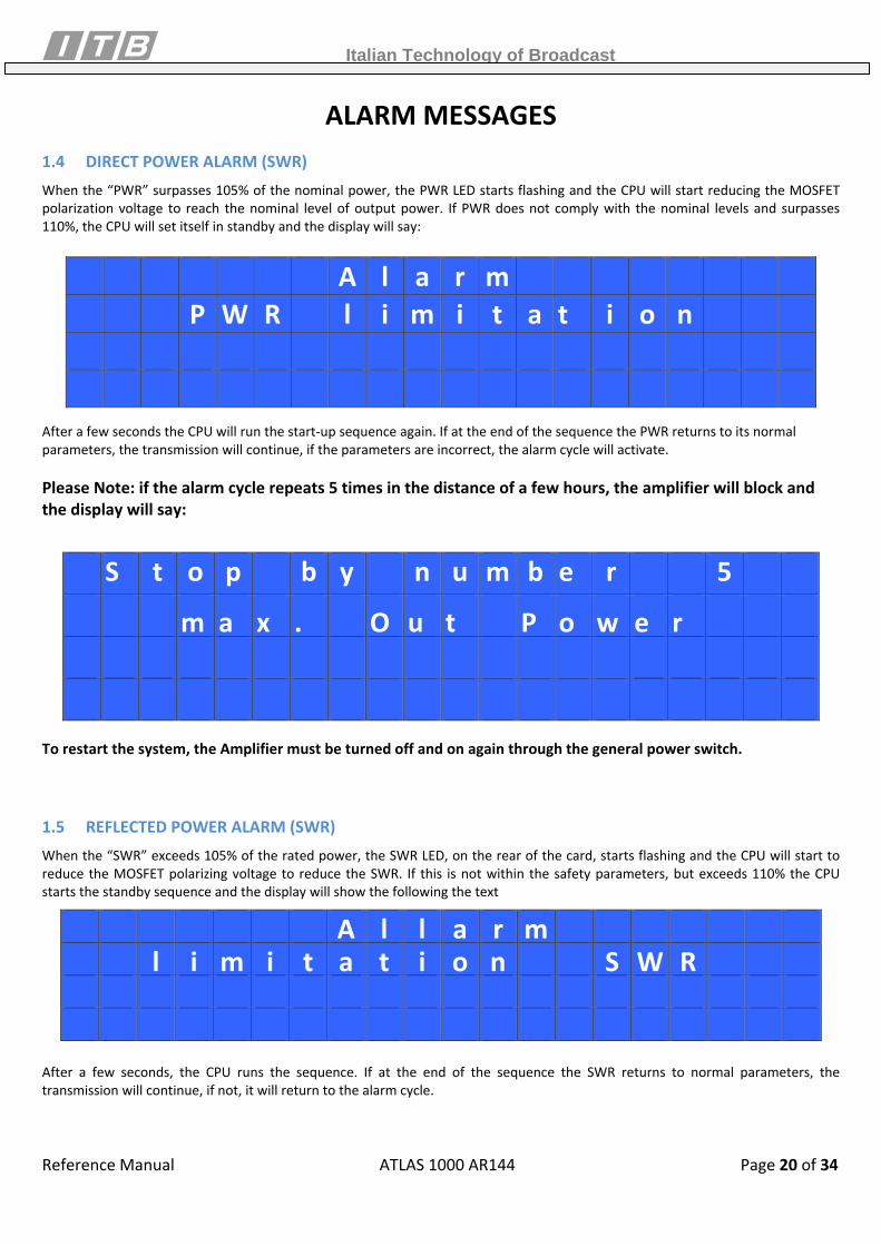
ALARM MESSAGES 1.4 DIRECT POWER ALARM (SWR) When the “PWR” surpasses 105% of the nominal power, the PWR LED starts flashing and the CPU will start reducing the MOSFET polarization voltage to reach the nominal level of output power. If PWR does not comply with the nominal levels and surpasses 110%, the CPU will set itself in standby and the display will say:
A l a r m P W R l i m i t a t i o n
After a few seconds the CPU will run the start‐up sequence again. If at the end of the sequence the PWR returns to its normal parameters, the transmission will continue, if the parameters are incorrect, the alarm cycle will activate. Please Note: if the alarm cycle repeats 5 times in the distance of a few hours, the amplifier will block and the display will say:
S t o p b y n u m b e r 5
m a x . O u t P o w e r
To restart the system, the Amplifier must be turned off and on again through the general power switch.
1.5 REFLECTED POWER ALARM (SWR) When the “SWR” exceeds 105% of the rated power, the SWR LED, on the rear of the card, starts flashing and the CPU will start to reduce the MOSFET polarizing voltage to reduce the SWR. If this is not within the safety parameters, but exceeds 110% the CPU starts the standby sequence and the display will show the following the text
A l l a r m l i m i t a t i o n S W R
After a few seconds, the CPU runs the sequence. If at the end of the sequence the SWR returns to normal parameters, the transmission will continue, if not, it will return to the alarm cycle.
Italian Technology of Broadcast
Reference Manual ATLAS 1000 AR144 Page 21 of 34
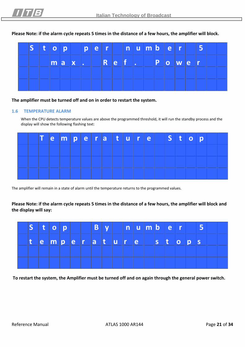
Please Note: if the alarm cycle repeats 5 times in the distance of a few hours, the amplifier will block.
S t o p p e r n u m b e r 5
m a x . R e f . P o w e r
The amplifier must be turned off and on in order to restart the system.
1.6 TEMPERATURE ALARM When the CPU detects temperature values are above the programmed threshold, it will run the standby process and the display will show the following flashing text:
T e m p e r a t u r e S t o p
The amplifier will remain in a state of alarm until the temperature returns to the programmed values. Please Note: if the alarm cycle repeats 5 times in the distance of a few hours, the amplifier will block and the display will say:
S t o p B y n u m b e r 5
t e m p e r a t u r e s t o p s
To restart the system, the Amplifier must be turned off and on again through the general power switch.
Italian Technology of Broadcast
Reference Manual ATLAS 1000 AR144 Page 22 of 34
SCHEMATICS and BILL OFF MATERIALS RF BOARD
Italian Technology of Broadcast
Reference Manual ATLAS 1000 AR144 Page 23 of 34
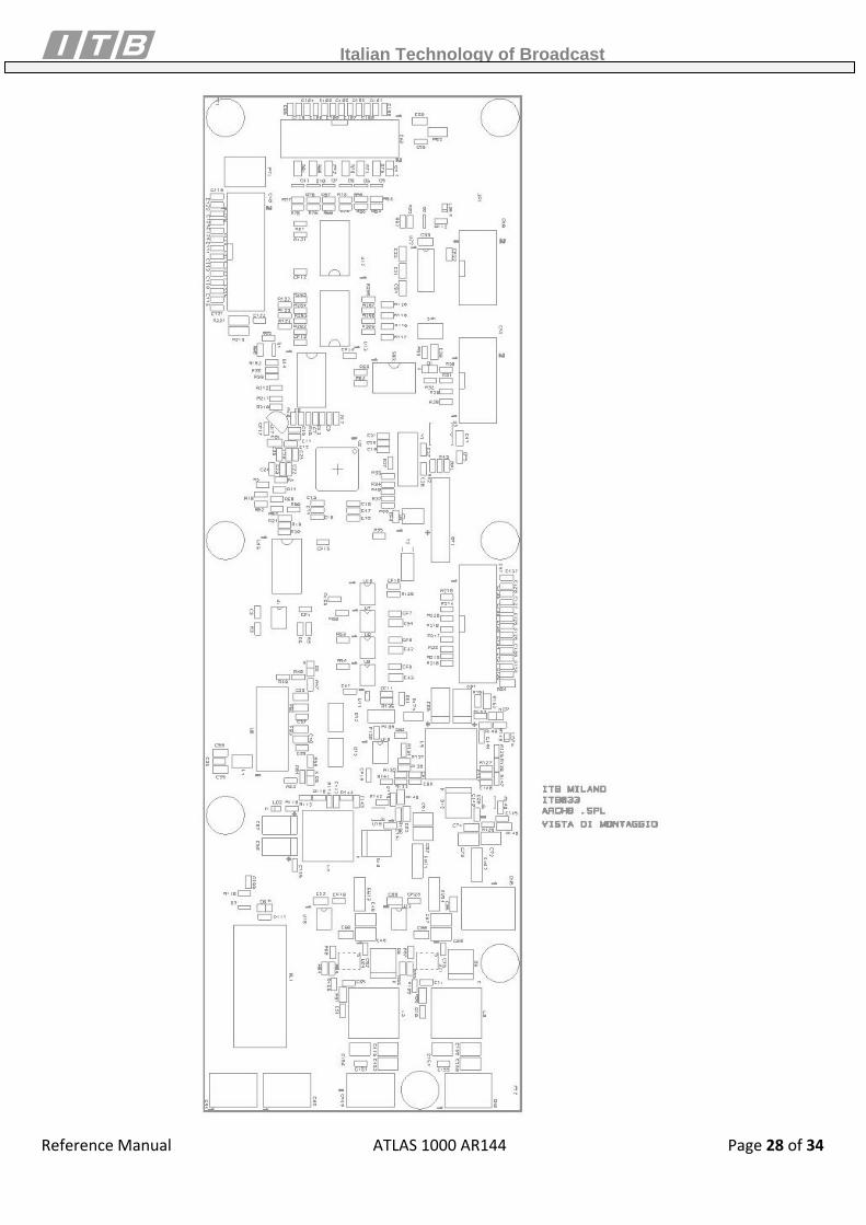
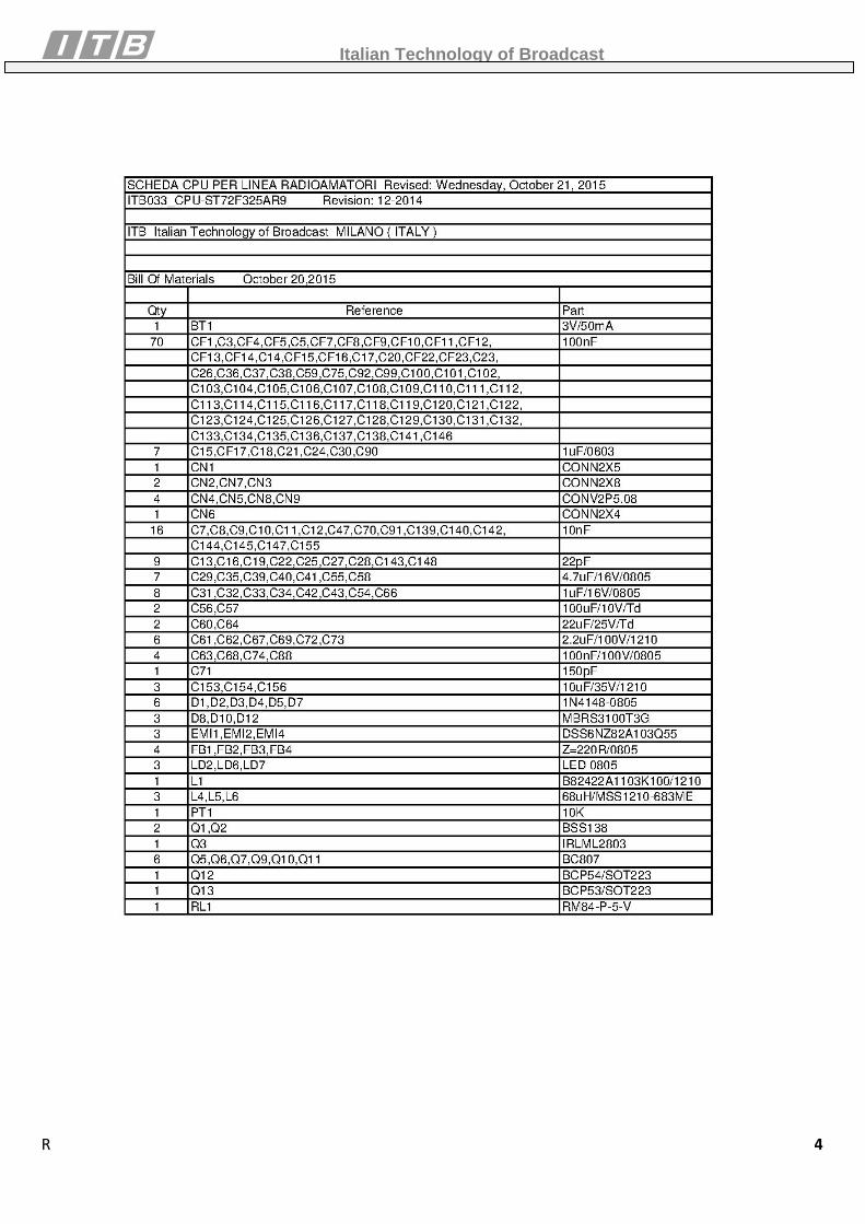
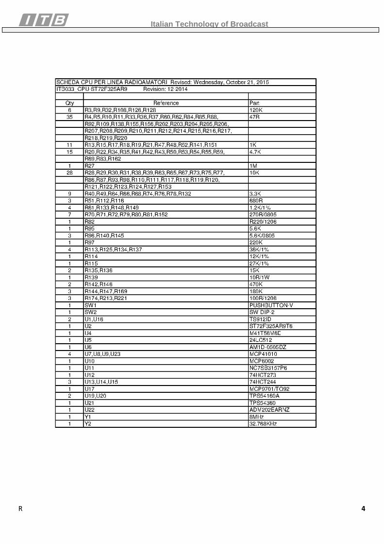
CPU BOARD
Italian Technology of Broadcast
Reference Manual ATLAS 1000 AR144 Page 24 of 34
Italian Technology of Broadcast
Reference Manual ATLAS 1000 AR144 Page 25 of 34
Italian Technology of Broadcast
Reference Manual ATLAS 1000 AR144 Page 26 of 34
Italian Technology of Broadcast
Reference Manual ATLAS 1000 AR144 Page 27 of 34
Italian Technology of Broadcast
Reference Manual ATLAS 1000 AR144 Page 28 of 34
Italian Technology of Broadcast
Reference Manual ATLAS 1000 AR144 Page 29 of 34
Italian Technology of Broadcast
Reference Manual ATLAS 1000 AR144 Page 30 of 34
Italian Technology of Broadcast
Reference Manual ATLAS 1000 AR144 Page 31 of 34
LED BOARD
Italian Technology of Broadcast
Reference Manual ATLAS 1000 AR144 Page 32 of 34
Italian Technology of Broadcast
Reference Manual ATLAS 1000 AR144 Page 33 of 34
ANALOG BOARD
Italian Technology of Broadcast
Reference Manual ATLAS 1000 AR144 Page 34 of 34