Embed Size (px)
Citation preview
RANGOTT MINERAL EXPLORATION PTY LTD
AUSTRALIAN DOLOMITE COMPANY PTY
LTD
‘Wonga’
Blast Management Plan
FOR PROPOSED GRANITE QUARRY
LOWES MOUNT ROAD, TARANA, NSW
Author: Paula Dell‐McCumstie Rangott Mineral Exploration Pty LtdPO Box 1141, Orange, NSW Tel: (02) 6362 5115 August 2015
TABLE OF CONTENTS………………………………………………………………………………….. Page
1.0 INTRODUCTION……………………………………………………………………………….. 1
2.0 PROPOSED ACTIVITIES……………………………………………………………………… 3
3.0 LEGAL AND OTHER REQUIREMENTS…………………………………………………. 4
4.0 OBJECTIVES AND OUTCOMES………………………………………………………….. 7
5.0 COMPETENCE TRAINING AND AWARENESS……………………………………… 8
6.0 SURROUNDING RESIDENCES…………………………………………………………….. 8
7.0 ANTICIPATED BLAST‐RELATED IMPACTS…………………………………………… 9
7.1 POTENTIAL IMPACT………………………………………………..….…. 9
7.1.1 Introduction………………………………………………………..………. 9
7.1.2 Airblast Overpressure Structural Impacts……….…….……… 9
7.1.3 Ground Vibration Structural Impacts…………………….……… 9
7.1.4 Blasting Guidance…………………………………………………..…… 10
7.2 PREDICTED LEVELS OF BLAST EMISSIONS……………………….…….… 11
8.0 MANAGEMENT MEASURES……………………………………….…………………….. 12
8.1 BLASTING COMPLIANCE………………………………………………….……… 12
8.2 BLASTING HOURS AND FREQUENCY…………………………………..…… 12
8.3 OPERATION CONDITIONS………………………………………………..…….. 12
8.3.1 Blasting Operations………………………………………………..…… 12
8.3.2 Flyrock and Dust Management………………………………..….. 12
8.3.3 Ground Vibration…………………………………………………..……. 15
8.3.4 Management of Airblast Overpressure…………………..…… 17
8.3.5 Blasting Safety Management…………………………………..….. 19
8.4 TEMPORARY CLOSURE OF LOWES MOUNT ROAD………………..…. 20
8.5 PROPOERTY INSPECTIONS……………………………………………….……… 20
8.6 PROPERTY INVESTIGATION……………………………………………………... 20
9.0 BLAST MONITORING………………………………………………………………………… 22
9.1 BLAST MONITORING REPORT………………………………………………..… 22
10 CORRECTIVE AND PREVENTATIVE ACTIONS…………………...................... 23
11 COMPLAINT HANDLING AND RESPONSE………………………….................. 24
12 INCIDENT REPORTING ……………………………………………………………………… 25
13 PUBLICATION OF MONITORING INFORMATION……………….................. 25
FIGURES: Figure Number Figure Title Scale Size
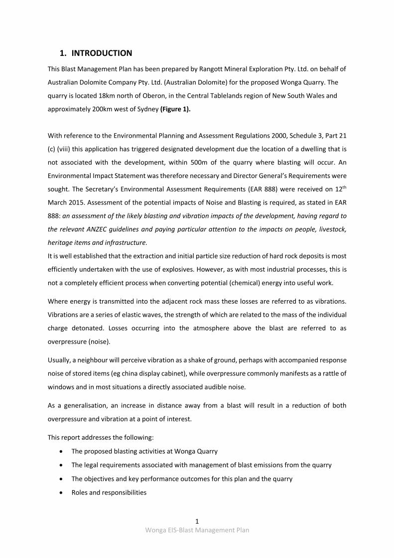
Figure 1 Project Site Regional Location 1:200,000 A4
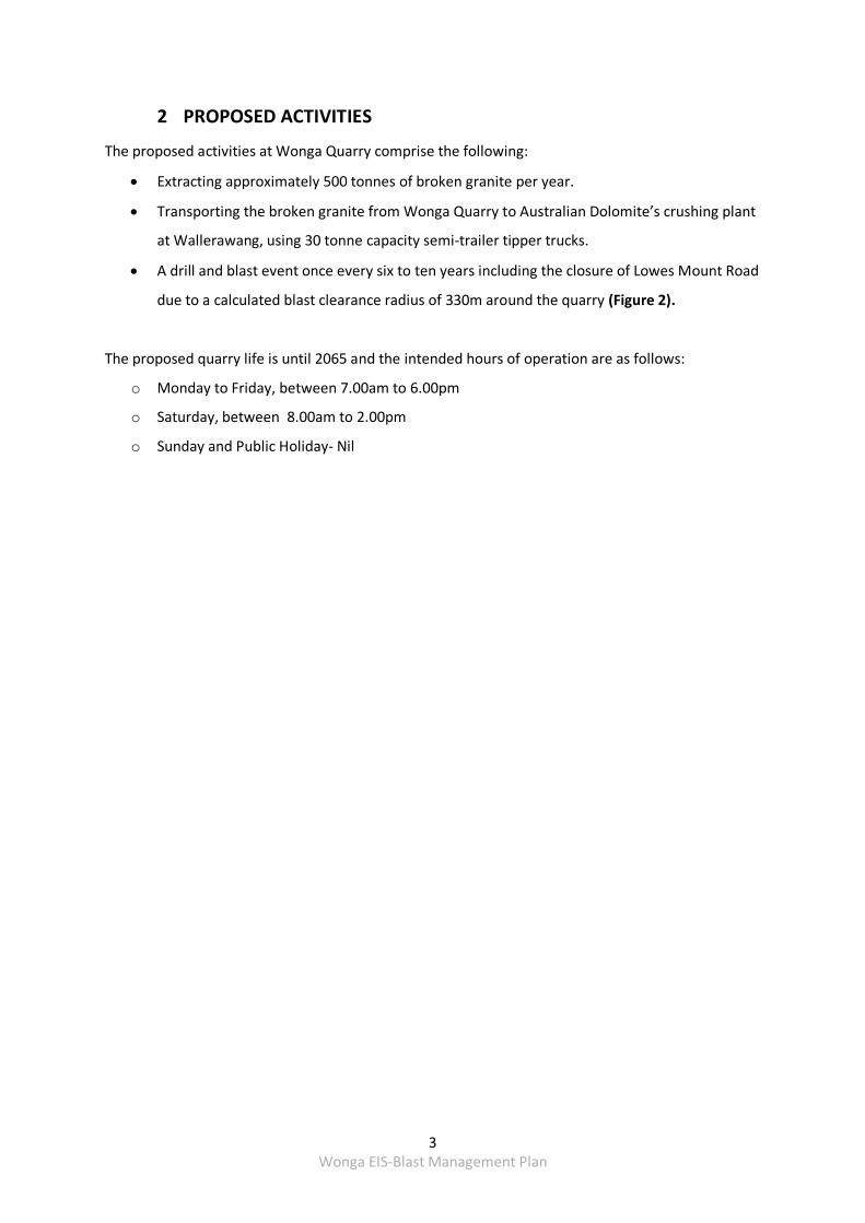
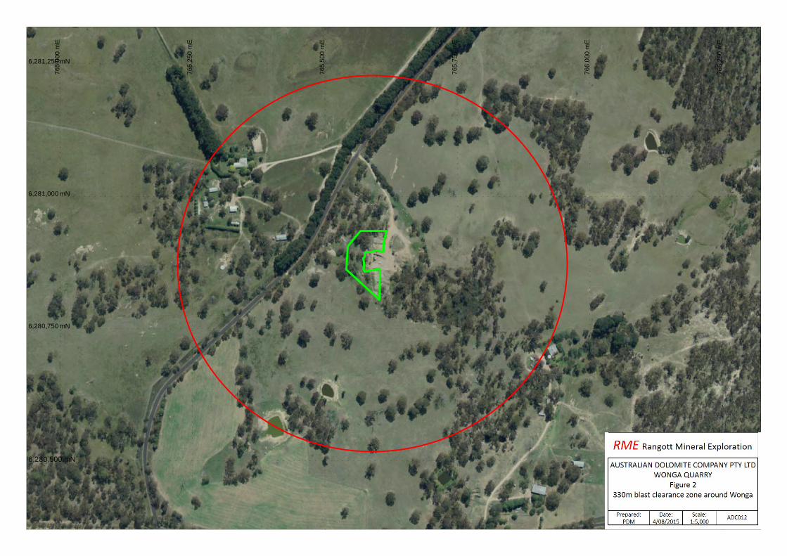
Figure 2 330m blast clearance radius around Wonga Quarry 1:5,000 A4
Figure 3 One kilometre radius around Wonga Quarry 1:12,500 A4
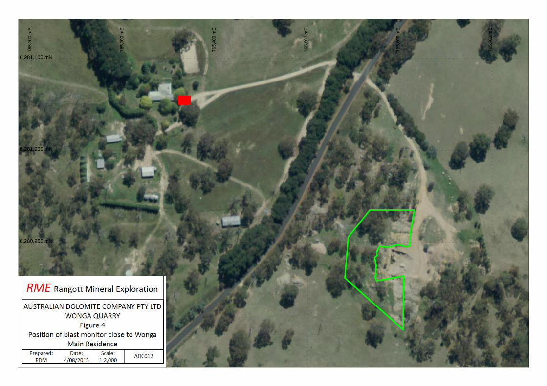
Figure 4 Position of blast monitor close to Wonga Main Residence
1: 2,000 A4
TABLES:
TABLES: Table Title Page
Table 1 Australian and New Zealand Environment Council (ANZEC) Technical basis for guidelines to minimise annoyance due to blasting overpressure and ground vibration Guidelines
5
Table 2 Objectives and Key Performance Outcomes 7
Table 3 Transient Vibration Guide for Cosmetic Damage (from BS 7385: Part 2: 1993
9
Table 4 Predicted Levels of Blast Emissions (Nitrotek Consulting). 11
Table 5 Blast design parameters used as the base case 14
Table 6 Range of particle shape factors with modelled value highlighted 14
Table 7 Estimated blast clearance distances 15
GRAPHS:
Graph Graph Title PageGraph 1 BS 7385: Part 2: 1993, Summary of Damage Thresholds for Transient Vibration
on Domestic Structure 10
Graph 2 Maximum probable vibration as a function of distance away from blasting activity
16
Graph 3 Maximum probable overpressure as a function of distance away from blasting activity
18
APPENDICES: APPENDIX I Fair Work Ombudsmen Best Practice Guide Effective Dispute Resolution
APPENDIX II Road Closure Plan for blasting at Wonga Quarry adjacent to Lowes Mount Road
APPENDIX III Example of Wonga Quarry Site Induction
APPENDIX IV Technical Report from Darren Francis, Principal Engineer, Nitrotek Consulting
1 Wonga EIS‐Blast Management Plan
1. INTRODUCTION
This Blast Management Plan has been prepared by Rangott Mineral Exploration Pty. Ltd. on behalf of
Australian Dolomite Company Pty. Ltd. (Australian Dolomite) for the proposed Wonga Quarry. The
quarry is located 18km north of Oberon, in the Central Tablelands region of New South Wales and
approximately 200km west of Sydney (Figure 1).
With reference to the Environmental Planning and Assessment Regulations 2000, Schedule 3, Part 21
(c) (viii) this application has triggered designated development due the location of a dwelling that is
not associated with the development, within 500m of the quarry where blasting will occur. An
Environmental Impact Statement was therefore necessary and Director General’s Requirements were
sought. The Secretary’s Environmental Assessment Requirements (EAR 888) were received on 12th
March 2015. Assessment of the potential impacts of Noise and Blasting is required, as stated in EAR
888: an assessment of the likely blasting and vibration impacts of the development, having regard to
the relevant ANZEC guidelines and paying particular attention to the impacts on people, livestock,
heritage items and infrastructure.
It is well established that the extraction and initial particle size reduction of hard rock deposits is most
efficiently undertaken with the use of explosives. However, as with most industrial processes, this is
not a completely efficient process when converting potential (chemical) energy into useful work.
Where energy is transmitted into the adjacent rock mass these losses are referred to as vibrations.
Vibrations are a series of elastic waves, the strength of which are related to the mass of the individual
charge detonated. Losses occurring into the atmosphere above the blast are referred to as
overpressure (noise).
Usually, a neighbour will perceive vibration as a shake of ground, perhaps with accompanied response
noise of stored items (eg china display cabinet), while overpressure commonly manifests as a rattle of
windows and in most situations a directly associated audible noise.
As a generalisation, an increase in distance away from a blast will result in a reduction of both
overpressure and vibration at a point of interest.
This report addresses the following:
The proposed blasting activities at Wonga Quarry
The legal requirements associated with management of blast emissions from the quarry
The objectives and key performance outcomes for this plan and the quarry
Roles and responsibilities
Bathurst
Oberon
O'ConnellTarana
WONGA QUARRY
2 Wonga EIS‐Blast Management Plan
Competence training and awareness
Surrounding residences and potential blast‐related impacts
Blast management measures
Blast‐related monitoring that will be undertaken
Evaluation of compliance with blast criteria
Corrective and preventative actions that will be implemented should exceedance(s) of the
relevant criteria be identified
Complaints handling and response procedures that will be implemented
Incident reporting procedures
Publication of monitoring information
The proposed quarry is fully described in the Environmental Impact Assessment dated June 2015 and
associated technical reports prepared to support the application documents and therefore no
further background information is provided in this plan.
3 Wonga EIS‐Blast Management Plan
2 PROPOSED ACTIVITIES
The proposed activities at Wonga Quarry comprise the following:
Extracting approximately 500 tonnes of broken granite per year.
Transporting the broken granite from Wonga Quarry to Australian Dolomite’s crushing plant
at Wallerawang, using 30 tonne capacity semi‐trailer tipper trucks.
A drill and blast event once every six to ten years including the closure of Lowes Mount Road
due to a calculated blast clearance radius of 330m around the quarry (Figure 2).
The proposed quarry life is until 2065 and the intended hours of operation are as follows:
o Monday to Friday, between 7.00am to 6.00pm
o Saturday, between 8.00am to 2.00pm
o Sunday and Public Holiday‐ Nil
765,
750
mE
766,
000
mE
766,
250
mE
6,281,250 mN
6,280,500 mN
6,280,750 mN
6,281,000 mN
765,
500
mE
765,
000
mE
765,
250
mE
4 Wonga EIS‐Blast Management Plan
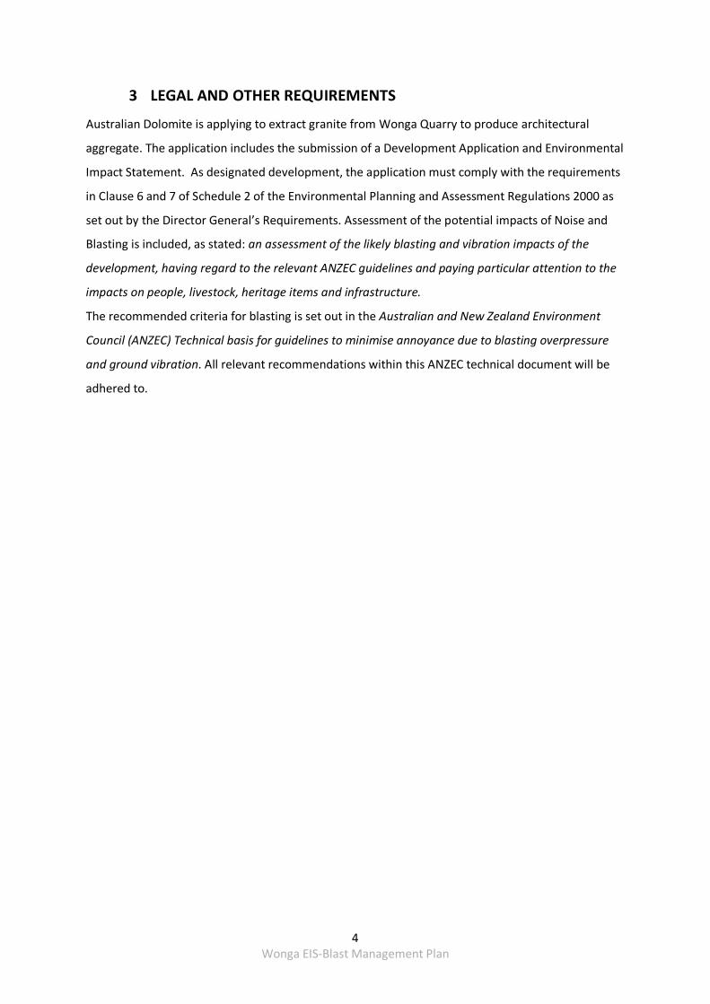
3 LEGAL AND OTHER REQUIREMENTS
Australian Dolomite is applying to extract granite from Wonga Quarry to produce architectural
aggregate. The application includes the submission of a Development Application and Environmental
Impact Statement. As designated development, the application must comply with the requirements
in Clause 6 and 7 of Schedule 2 of the Environmental Planning and Assessment Regulations 2000 as
set out by the Director General’s Requirements. Assessment of the potential impacts of Noise and
Blasting is included, as stated: an assessment of the likely blasting and vibration impacts of the
development, having regard to the relevant ANZEC guidelines and paying particular attention to the
impacts on people, livestock, heritage items and infrastructure.
The recommended criteria for blasting is set out in the Australian and New Zealand Environment
Council (ANZEC) Technical basis for guidelines to minimise annoyance due to blasting overpressure
and ground vibration. All relevant recommendations within this ANZEC technical document will be
adhered to.
5 Wonga EIS‐Blast Management Plan
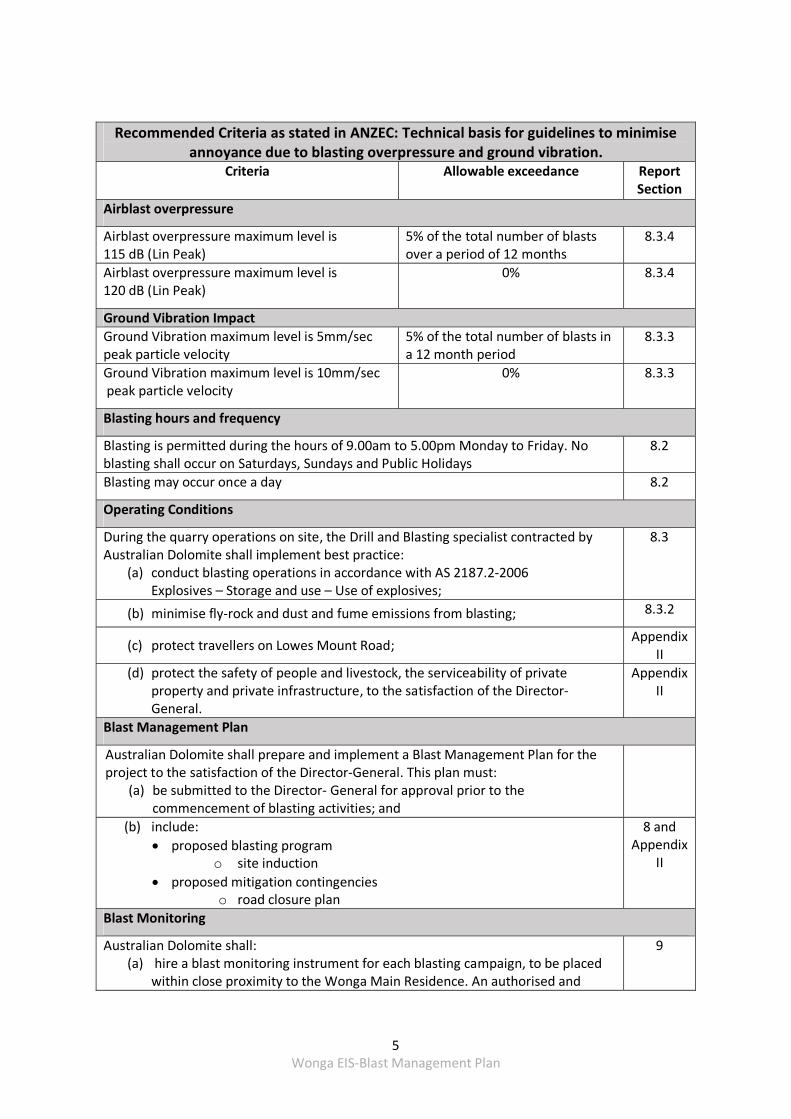
Recommended Criteria as stated in ANZEC: Technical basis for guidelines to minimise annoyance due to blasting overpressure and ground vibration.
Criteria Allowable exceedance Report Section
Airblast overpressure
Airblast overpressure maximum level is 115 dB (Lin Peak)
5% of the total number of blasts over a period of 12 months
8.3.4
Airblast overpressure maximum level is 120 dB (Lin Peak)
0% 8.3.4
Ground Vibration Impact
Ground Vibration maximum level is 5mm/sec peak particle velocity
5% of the total number of blasts in a 12 month period
8.3.3
Ground Vibration maximum level is 10mm/sec peak particle velocity
0% 8.3.3
Blasting hours and frequency
Blasting is permitted during the hours of 9.00am to 5.00pm Monday to Friday. No blasting shall occur on Saturdays, Sundays and Public Holidays
8.2
Blasting may occur once a day 8.2
Operating Conditions
During the quarry operations on site, the Drill and Blasting specialist contracted by Australian Dolomite shall implement best practice:
(a) conduct blasting operations in accordance with AS 2187.2‐2006 Explosives – Storage and use – Use of explosives;
8.3
(b) minimise fly‐rock and dust and fume emissions from blasting; 8.3.2
(c) protect travellers on Lowes Mount Road; Appendix
II
(d) protect the safety of people and livestock, the serviceability of private property and private infrastructure, to the satisfaction of the Director‐General.
Appendix II
Blast Management Plan
Australian Dolomite shall prepare and implement a Blast Management Plan for the project to the satisfaction of the Director‐General. This plan must:
(a) be submitted to the Director‐ General for approval prior to the commencement of blasting activities; and
(b) include:
proposed blasting programo site induction
proposed mitigation contingencieso road closure plan
8 and Appendix
II
Blast Monitoring
Australian Dolomite shall: (a) hire a blast monitoring instrument for each blasting campaign, to be placed
within close proximity to the Wonga Main Residence. An authorised and
9
6 Wonga EIS‐Blast Management Plan
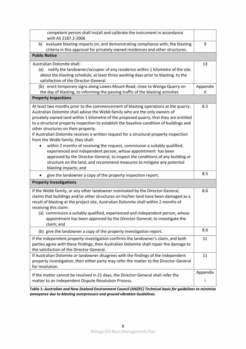
competent person shall install and calibrate the instrument in accordance with AS 2187.2‐2006
b) evaluate blasting impacts on, and demonstrating compliance with, the blastingcriteria in this approval for privately‐owned residences and other structures.
9
Public Notice
Australian Dolomite shall: (a) notify the landowner/occupier of any residence within 1 kilometre of the site about the blasting schedule, at least three working days prior to blasting, to the satisfaction of the Director‐General
13
(b) erect temporary signs along Lowes Mount Road, close to Wonga Quarry on the day of blasting, to informing the passing traffic of the blasting activities
Appendix II
Property Inspections
At least two months prior to the commencement of blasting operations at the quarry, Australian Dolomite shall advise the Webb family who are the only owners of privately‐owned land within 1 kilometre of the proposed quarry, that they are entitled to a structural property inspection to establish the baseline condition of buildings and other structures on their property. If Australian Dolomite receives a written request for a structural property inspection from the Webb family, they shall:
within 2 months of receiving the request, commission a suitably qualified,experienced and independent person, whose appointment has been approved by the Director‐General, to inspect the conditions of any building or structure on the land, and recommend measures to mitigate any potential blasting impacts; and
8.5
give the landowner a copy of the property inspection report. 8.5
Property Investigations
If the Webb family, or any other landowner nominated by the Director‐General, claims that buildings and/or other structures on his/her land have been damaged as a result of blasting at the project site, Australian Dolomite shall within 2 months of receiving this claim:
(a) commission a suitably qualified, experienced and independent person, whose appointment has been approved by the Director‐General, to investigate the claim; and
8.6
(b) give the landowner a copy of the property investigation report. 8.6
If the independent property investigation confirms the landowner’s claim, and both parties agree with these findings, then Australian Dolomite shall repair the damage to the satisfaction of the Director‐General.
11
If Australian Dolomite or landowner disagrees with the findings of the independent property investigation, then either party may refer the matter to the Director‐General for resolution.
11
If the matter cannot be resolved in 21 days, the Director‐General shall refer the matter to an independent Dispute Resolution Process.
Appendix
I
Table 1: Australian and New Zealand Environment Council (ANZEC) Technical basis for guidelines to minimise annoyance due to blasting overpressure and ground vibration Guidelines
7 Wonga EIS‐Blast Management Plan
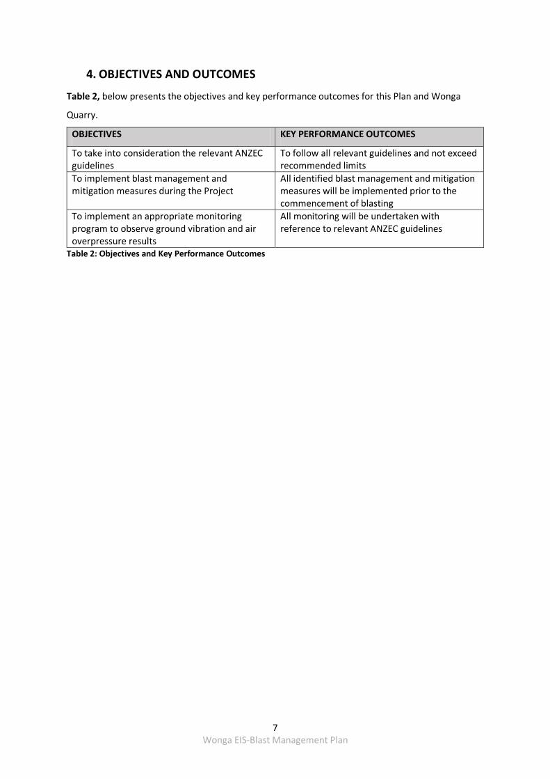
4. OBJECTIVES AND OUTCOMES
Table 2, below presents the objectives and key performance outcomes for this Plan and Wonga
Quarry.
OBJECTIVES KEY PERFORMANCE OUTCOMES
To take into consideration the relevant ANZEC guidelines
To follow all relevant guidelines and not exceed recommended limits
To implement blast management and mitigation measures during the Project
All identified blast management and mitigation measures will be implemented prior to the commencement of blasting
To implement an appropriate monitoring program to observe ground vibration and air overpressure results
All monitoring will be undertaken with reference to relevant ANZEC guidelines
Table 2: Objectives and Key Performance Outcomes
8 Wonga EIS‐Blast Management Plan
5. COMPETENCE TRAINING AND AWARENESS
Blasting at Wonga Quarry is likely to occur once every six to ten years, therefore a Drill and Blasting
Specialist will be contracted by Australian Dolomite to carry out blasting when required. The blasting
specialist will be fully competent in blast management awareness focussing on the following:
Awareness of the blast emissions enhancing effects of temperature inversion and the times
of day and meteorological conditions under which they may occur
Awareness of safety for travellers on Lowes Mount Road, surrounding residents and
livestock and implement the attached Road Closure Plan (Appendix II).
Awareness of explosive storage, transport and use in accordance with AS 2187.2‐2006
Explosive Storage, Transport and Use
Minimising flyrock and dust emissions from blasting
Awareness of restricted blast operating hours and frequency
Monitoring of blast emissions at required residences
Ensure all personnel adhere to the site induction
Australian Dolomite is responsible for ensuring that blast management plan is adhered to by the Site
Supervisor and Drill and Blasting Specialist.
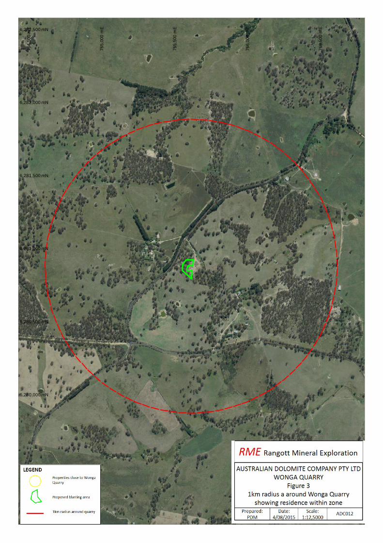
6. SURROUNDING RESIDENCES
Figure 3 displays the locations of the residences within 1 kilometre of the Project site.
6,279,500 mN
6,280,000 mN
6,280,500 mN
6,281,500 mN
6,282,000 mN
6,282,500 mN
765,
500
mE
764,
500
mE
765,
000
mE
766,
000
mE
766,
500
mE
6,281,000 mN
9 Wonga EIS‐Blast Management Plan
7. ANTICIPATED BLAST‐RELATED IMPACTS
This section describes the predicted potential airblast overpressure and ground vibration structural
impacts of blasting and the blast emission levels.
7.1 POTENTIAL IMPACTS
7.1.1 Introduction
Airblast overpressure is a pressure wave that travels through the air following a blast, while ground
vibration is caused by energy from the blast travelling through the intervening rock strata
surrounding the blast location.
7.1.2 Airblast Overpressure Structural Impacts
Plaster that cracked within residences is the type of damage that is monitored in most airblast
overpressure complaints.
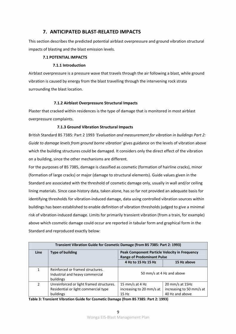
7.1.3 Ground Vibration Structural Impacts
British Standard BS 7385: Part 2 1993 ‘Evaluation and measurement for vibration in buildings Part 2:
Guide to damage levels from ground borne vibration’ gives guidance on the levels of vibration above
which the building structures could be damaged. It considers only the direct effect of the vibration
on a building, since the other mechanisms are different.
For the purposes of BS 7385, damage is classified as cosmetic (formation of hairline cracks), minor
(formation of large cracks) or major (damage to structural elements). Guide values given in the
Standard are associated with the threshold of cosmetic damage only, usually in wall and/or ceiling
lining materials. Since case‐history data, taken alone, has so far not provided an adequate basis for
identifying thresholds for vibration‐induced damage, data using controlled vibration sources within
buildings has been established to enable definition of vibration thresholds judged to give a minimal
risk of vibration‐induced damage. Limits for primarily transient vibration (from a train, for example)
above which cosmetic damage could occur are reported in tabular form and graphical form in the
Standard and reproduced exactly below:
Transient Vibration Guide for Cosmetic Damage (from BS 7385: Part 2: 1993)
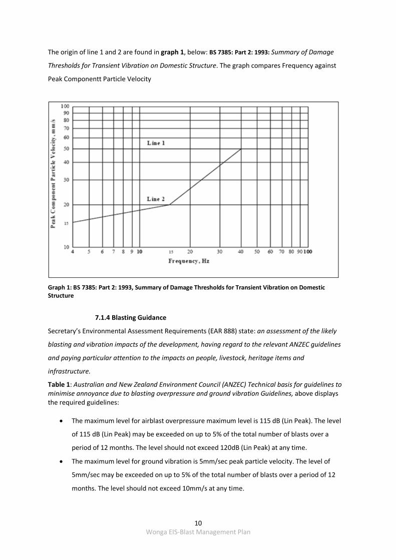
Line Type of building Peak Component Particle Velocity in Frequency Range of Predominant Pulse
4 Hz to 15 Hz 15 Hz 15 Hz above
1 Reinforced or framed structures. Industrial and heavy commercial buildings
50 mm/s at 4 Hz and above
2 Unreinforced or light framed structures. Residential or light commercial type buildings
15 mm/s at 4 Hz increasing to 20 mm/s at 15 Hz
20 mm/s at 15Hz increasing to 50 mm/s at 40 Hz and above
Table 3: Transient Vibration Guide for Cosmetic Damage (from BS 7385: Part 2: 1993)
10 Wonga EIS‐Blast Management Plan
The origin of line 1 and 2 are found in graph 1, below: BS 7385: Part 2: 1993: Summary of Damage
Thresholds for Transient Vibration on Domestic Structure. The graph compares Frequency against
Peak Componentt Particle Velocity
Graph 1: BS 7385: Part 2: 1993, Summary of Damage Thresholds for Transient Vibration on Domestic Structure
7.1.4 Blasting Guidance
Secretary’s Environmental Assessment Requirements (EAR 888) state: an assessment of the likely
blasting and vibration impacts of the development, having regard to the relevant ANZEC guidelines
and paying particular attention to the impacts on people, livestock, heritage items and
infrastructure.
Table 1: Australian and New Zealand Environment Council (ANZEC) Technical basis for guidelines to minimise annoyance due to blasting overpressure and ground vibration Guidelines, above displays the required guidelines:
The maximum level for airblast overpressure maximum level is 115 dB (Lin Peak). The level
of 115 dB (Lin Peak) may be exceeded on up to 5% of the total number of blasts over a
period of 12 months. The level should not exceed 120dB (Lin Peak) at any time.
The maximum level for ground vibration is 5mm/sec peak particle velocity. The level of
5mm/sec may be exceeded on up to 5% of the total number of blasts over a period of 12
months. The level should not exceed 10mm/s at any time.
11 Wonga EIS‐Blast Management Plan
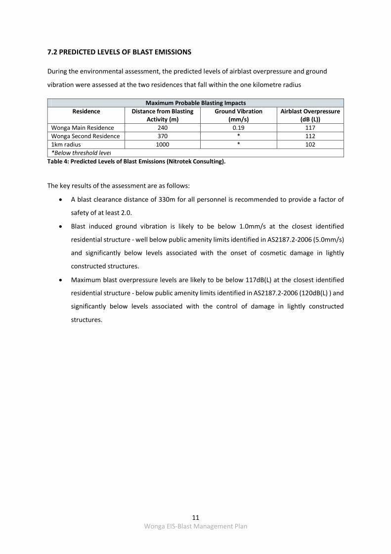
7.2 PREDICTED LEVELS OF BLAST EMISSIONS
During the environmental assessment, the predicted levels of airblast overpressure and ground
vibration were assessed at the two residences that fall within the one kilometre radius
Maximum Probable Blasting Impacts
Residence Distance from BlastingActivity (m)
Ground Vibration (mm/s)
Airblast Overpressure(dB (L))
Wonga Main Residence 240 0.19 117
Wonga Second Residence 370 * 112
1km radius 1000 * 102
*Below threshold level
Table 4: Predicted Levels of Blast Emissions (Nitrotek Consulting).
The key results of the assessment are as follows:
A blast clearance distance of 330m for all personnel is recommended to provide a factor of
safety of at least 2.0.
Blast induced ground vibration is likely to be below 1.0mm/s at the closest identified
residential structure ‐ well below public amenity limits identified in AS2187.2‐2006 (5.0mm/s)
and significantly below levels associated with the onset of cosmetic damage in lightly
constructed structures.
Maximum blast overpressure levels are likely to be below 117dB(L) at the closest identified
residential structure ‐ below public amenity limits identified in AS2187.2‐2006 (120dB(L) ) and
significantly below levels associated with the control of damage in lightly constructed
structures.
12 Wonga EIS‐Blast Management Plan
8. MANAGEMENT MEASURES
EAR 888 requires this plan to describe mitigation measures that will be adopted to ensure
compliance with ANZEC Technical basis for guidelines to minimise annoyance due to blasting
overpressure and ground vibration Guidelines, paying particular attention to the impacts on people,
livestock, heritage items and infrastructure. Oberon Council require that the close proximity to
Lowes Mount Road be investigated. This section has been prepared in satisfaction of those
guidelines.
8.1 BLASTING COMPLIANCE
Australian Standard 2187.2 Explosive Storage, Transport and Use states:
that blasting will only be undertaken by qualified personnel or contractors
blasting personnel or contractors operate under AS 2187.2
Australian Dolomite will be responsible to ensure blasting is carried out according to the relevant
standard.
8.2 BLASTING HOURS AND FREQUENCY
Australian Dolomite will ensure that the operating hours and conditions identified in ANZEC
Technical basis for guidelines to minimise annoyance due to blasting overpressure and ground
vibration Guidelines will be adhered to.
Australian Dolomite will be responsible for ensuring the operating hours are included in the site
induction and that no breaches of this condition will be tolerated.
Blasting is recommended only once a day.
8.3 OPERATING CONDITIONS
8.3.1 Blasting Operations
All blasting will adhere to the specific recommendations within AS2187.2 – 2006, such that the
project will observe all regulations for blasting where safe handling and use of explosives is
implemented at the Wonga Quarry Project through a defined Blast Management Plan (BMP).
8.3.2 Flyrock and Dust Management
The control of flyrock is a relatively complex interaction between blast design, diligent operational
application and local geology. However, the issue of maintaining personnel safety demands a strong
engineering basis to ensure safety under all blasting conditions at all times. Experience has shown
13 Wonga EIS‐Blast Management Plan
that flyrock projection distance estimations and subsequent selection of appropriate clearance
zones must be carefully assessed with as complete knowledge as possible of each individual blasting
application.
Best practice blasting incorporates a level of redundancy within the blast design to ensure an
acceptable factor of safety is maintained even in the event of unintended unknown deviations
during application of the design (such as shorter stemming lengths).
Various studies have sought to generate predictive equations for maximum flyrock range and are
generally based on consideration of:
Rock density
Blast hole diameter
Explosive density
Confinement levels
Particle size achieving maximum range
The equations developed, combined with other known equations of motion allow the determination
of practical limits for any charge configuration, blast hole size, rock type and shape factor (ratio of
surface area to volume). More recently, improved realistic particle motion has been achieved by
incorporating the additional influence of air resistance for estimated particle trajectories.
The calculation adopted for the Wonga Quarry site combines all of the points mentioned above into
a succinct form:
〖Range〗_max=11 ×〖SDB〗^(‐2.167) (∅/F_s )^0.667 (Equation 1)
where Φ is the hole diameter in mm, Fs is the shape factor, SDB is the scaled depth of burial
equation and Rangemax is the maximum probable flyrock projection. The scaled depth of burial
component provides a relationship to define the relative confinement of the explosive charge and is
defined as:
SDB= d_c/∛MJ (Equation 2)
where d_c is the depth from the collar of the blast hole to the cratering charge centroid (cratering
charge assumed to be equivalent to 8 times the blast hole diameter) and MJ is the explosive energy
contained in the cratering charge.
In order to progress the investigation, a base case blast design is required and has been completed.
Little historic blast design data and no geotechnical data is available at this time to guide the blast
design process. Operational parameters and initial rock mass data have been selected based on
experience of similar material. For the Wonga Quarry site the following criteria have been adopted:
• Individual blast to produce 5 years supply of material
14 Wonga EIS‐Blast Management Plan
• Intact rock strength in the order of 110MPa to 140Mpa
• Intact rock ‐ Young's Modulus = 62GPa
• Intact rock ‐ Poisson's Ratio = 0.32
• Working face height = 4.0m
• Blast hole diameter = 89mm
• Bulk explosive density = 1.10g/cc
The onset of fresh fracture in rock due to rapid strain rates (known as the critical vibration level ‐
PPVcritical) has been well documented and can be used to provide a first estimate of a productive
blast pattern design. Here, a multiple of 4 times the PPVcritical generally achieves good levels of
fragmentation and results in the following parameters for the base case blast design:
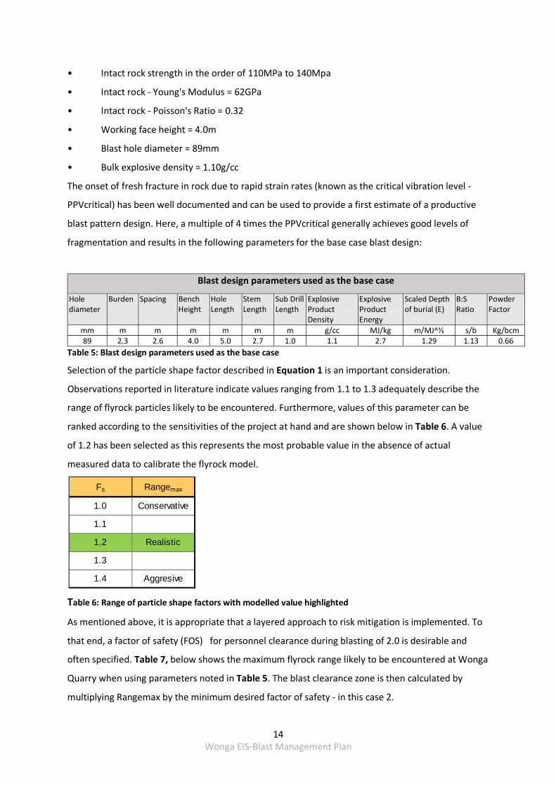
Blast design parameters used as the base case
Hole diameter
Burden Spacing Bench Height
Hole Length
Stem Length
Sub Drill Length
Explosive Product Density
Explosive Product Energy
Scaled Depth of burial (E)
B:S Ratio
Powder Factor
mm m m m m m m g/cc MJ/kg m/MJ^⅓ s/b Kg/bcm89 2.3 2.6 4.0 5.0 2.7 1.0 1.1 2.7 1.29 1.13 0.66
Table 5: Blast design parameters used as the base case
Selection of the particle shape factor described in Equation 1 is an important consideration.
Observations reported in literature indicate values ranging from 1.1 to 1.3 adequately describe the
range of flyrock particles likely to be encountered. Furthermore, values of this parameter can be
ranked according to the sensitivities of the project at hand and are shown below in Table 6. A value
of 1.2 has been selected as this represents the most probable value in the absence of actual
measured data to calibrate the flyrock model.
Table 6: Range of particle shape factors with modelled value highlighted
As mentioned above, it is appropriate that a layered approach to risk mitigation is implemented. To
that end, a factor of safety (FOS) for personnel clearance during blasting of 2.0 is desirable and
often specified. Table 7, below shows the maximum flyrock range likely to be encountered at Wonga
Quarry when using parameters noted in Table 5. The blast clearance zone is then calculated by
multiplying Rangemax by the minimum desired factor of safety ‐ in this case 2.
Fs Rangemax
1.0 Conservative
1.1
1.2 Realistic
1.3
1.4 Aggresive
15 Wonga EIS‐Blast Management Plan
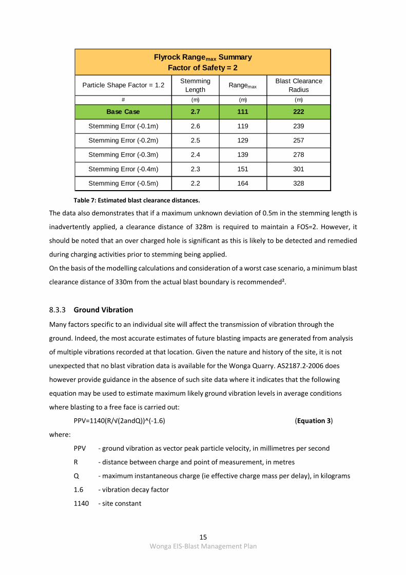
Table 7: Estimated blast clearance distances.
The data also demonstrates that if a maximum unknown deviation of 0.5m in the stemming length is
inadvertently applied, a clearance distance of 328m is required to maintain a FOS=2. However, it
should be noted that an over charged hole is significant as this is likely to be detected and remedied
during charging activities prior to stemming being applied.
On the basis of the modelling calculations and consideration of a worst case scenario, a minimum blast
clearance distance of 330m from the actual blast boundary is recommended².
8.3.3 Ground Vibration
Many factors specific to an individual site will affect the transmission of vibration through the
ground. Indeed, the most accurate estimates of future blasting impacts are generated from analysis
of multiple vibrations recorded at that location. Given the nature and history of the site, it is not
unexpected that no blast vibration data is available for the Wonga Quarry. AS2187.2‐2006 does
however provide guidance in the absence of such site data where it indicates that the following
equation may be used to estimate maximum likely ground vibration levels in average conditions
where blasting to a free face is carried out:
PPV=1140(R/√(2andQ))^(‐1.6) (Equation 3)
where:
PPV ‐ ground vibration as vector peak particle velocity, in millimetres per second
R ‐ distance between charge and point of measurement, in metres
Q ‐ maximum instantaneous charge (ie effective charge mass per delay), in kilograms
1.6 ‐ vibration decay factor
1140 ‐ site constant
Particle Shape Factor = 1.2Stemming
LengthRangemax
Blast Clearance Radius
# (m) (m) (m)
Base Case 2.7 111 222
Stemming Error (-0.1m) 2.6 119 239
Stemming Error (-0.2m) 2.5 129 257
Stemming Error (-0.3m) 2.4 139 278
Stemming Error (-0.4m) 2.3 151 301
Stemming Error (-0.5m) 2.2 164 328
Flyrock Rangemax SummaryFactor of Safety = 2
16 Wonga EIS‐Blast Management Plan
Published data relating specifically to granite formations indicate that the actual decay factor, a
measure of how rapidly elastic strain waves (ie vibration) attenuate over distance, is greater with
values ranging from 2.1 to 2.4. Site constants are similarly noted to vary from that provided in
Equation 3 with values ranging from 500 to 1300. It is appropriate in this case to modify the
AS2187.2 estimates for decay factor and site constant values based on these published values
combined with operational experience in similar materials to the following values:
vibration decay factor = 2.1
site constant = 1050
The selected values retain a level of conservatism appropriate to the planned operational nature of
the site. For Wonga Quarry, the following equation may be used with a high degree of confidence to
estimate maximum likely ground vibration levels at any point of interest:
PPV=1050(R/√(2andQ))^(‐2.1) (Equation 4)
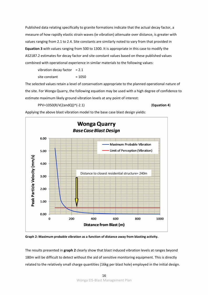
Applying the above blast vibration model to the base case blast design yields:
Graph 2: Maximum probable vibration as a function of distance away from blasting activity.
The results presented in graph 2 clearly show that blast induced vibration levels at ranges beyond
180m will be difficult to detect without the aid of sensitive monitoring equipment. This is directly
related to the relatively small charge quantities (16kg per blast hole) employed in the initial design.
Distance to closest residential structure= 240m
17 Wonga EIS‐Blast Management Plan
The closest identified residential structure is located at a range of approximately 240m. Estimated
vibration levels at this distance are in the order of 10 times lower than the public amenity level of
5.0mm/s recommended in AS2187.2‐2006 for blasting operations. Likewise, this is many times lower
than any of the commonly accepted limits for the onset of cosmetic damage to residential and
similar lightly fabricated structures.
8.3.4 Management Airblast Overpressure
Overpressure is a measurement of the pressure levels transmitted into the atmosphere radiating
outwards from the source. It has been documented that well confined blasts generate pressure
waves at frequencies predominantly below 20Hz, with relatively small amounts of energy contained
in frequencies greater than this level. It is important to note that the human ear does not respond to
noise with frequencies below the 20Hz level. However, it is equally important to note that buildings
tend to respond to frequencies in the range of 2 to 20Hz. It is on this basis that most monitoring for
human response to noise utilises a filtered sound level where frequencies below 20Hz are removed.
This is known as the decibel (A) scale ‐ or dB(A) scale. As blasting generally produces frequencies
predominantly below 20Hz, atmospheric overpressure levels are recorded using the decibel (Linear)
scale ‐ or dB(L).
Again, as with the case for blast vibration estimation, the most accurate estimations of overpressure
rely on calibrating site specific models using actual recorded data. These models tend to rely on
established scaling methods which seek to establish the relationship between explosive charge mass
detonated per delay period, the range to the point of interest and the overpressure level. The
following cube root scaling formula is commonly utilised:
P=K(D/∛W)^a (Equation 5)
where
P ‐ sound pressure level (kPa)
D ‐ distance from charge (m)
W ‐ explosive charge mass per delay (kg)
K ‐ site constant
a ‐ site exponent
Without the assistance of actual historic data, published data has been accessed. For average
confinement levels in typical quarry blasting applications, values of the site constant K commonly
range between 3.15 (good confinement) to 31.5 (extremely poor confinement) for a site exponent
(a) of ‐1.2. Appropriate initial values for Wonga Quarry Project have been selected:
18 Wonga EIS‐Blast Management Plan
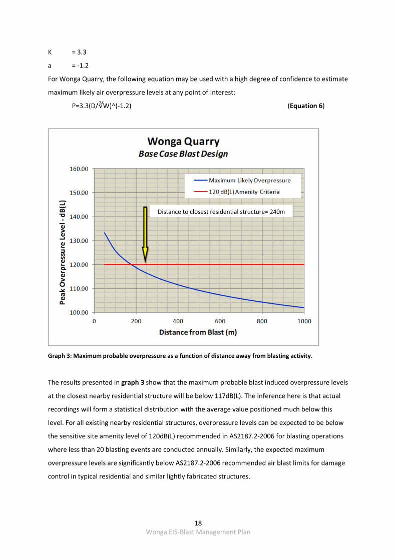
K = 3.3
a = ‐1.2
For Wonga Quarry, the following equation may be used with a high degree of confidence to estimate
maximum likely air overpressure levels at any point of interest:
P=3.3(D/∛W)^(‐1.2) (Equation 6)
Graph 3: Maximum probable overpressure as a function of distance away from blasting activity.
The results presented in graph 3 show that the maximum probable blast induced overpressure levels
at the closest nearby residential structure will be below 117dB(L). The inference here is that actual
recordings will form a statistical distribution with the average value positioned much below this
level. For all existing nearby residential structures, overpressure levels can be expected to be below
the sensitive site amenity level of 120dB(L) recommended in AS2187.2‐2006 for blasting operations
where less than 20 blasting events are conducted annually. Similarly, the expected maximum
overpressure levels are significantly below AS2187.2‐2006 recommended air blast limits for damage
control in typical residential and similar lightly fabricated structures.
Distance to closest residential structure= 240m
19 Wonga EIS‐Blast Management Plan
As indicated in Table 4, airblast overpressure at Wonga main property will have a maximum of 117
dB (L). As identified in ANZEC Technical basis for guidelines to minimise annoyance due to blasting
overpressure and ground vibration Guidelines, the relevant criteria for airblast overpressure is 115
dB Linear, with exceedances of this level permitted during no more than 5% of blasts in any 12
months period. In order to achieve compliance with this requirement, Australian Dolomite will
implement the following when blasting within the section of the Extraction Area closest to Wonga
main property,
Maximum instantaneous charges will be adjusted to ensure compliance with the
115 dB Linear criteria
Blasts will not be initiated, where practicable, during temperature inversion, when
low cloud is present or when the wind is blowing from the southeast
8.3.5 BLASTING SAFETY MEASURE
Oberon Council’s request of 9th July 2015 and EAR 888 require the protection of travellers on Lowes
Mount Road, people, livestock, heritage items and infrastructure.
As no heritage items were identified in the project area during the Environmental Assessment, this
does not need to be mitigated. The requirement for safety measures for Lowes Mount Road, people,
Wonga properties and livestock still apply. The following will be implemented:
Review location of blast and its proximity to Lowes Mount Road, the presence of
landowners, property and livestock and determine the appropriate exclusion zone
Where required, blasts should be orientated such that flyrock will be directed away from
Lowes Mount Road, Wonga properties, people or livestock
Advise surrounding landholders within 2km of the blast three days prior to blasting of the
date and times of the blast.
Temporarily close Lowes Mount Road. A Road Closure Plan is attached in Appendix II
Inspect blasts to determine if flyrock has propelled outside the blast envelope and
investigate where appropriate
Design blasts to minimise uncontrolled flyrock by the Principal Blast Engineer, Nitrotek
Consulting
Ensure blasting personnel are competent by employing Specialist Drill and Blasting
Contractors
Australian Dolomite will be responsible for ensuring that the relevant safety measures have been
implemented prior to blasting within the Quarry.
20 Wonga EIS‐Blast Management Plan
8.4 TEMPORARY CLOSURE OF LOWES MOUNT ROAD
Due to the close proximity of Wonga Quarry to Lowes Mount Road, it is recommended that the road
be closed for a period of time prior to blasting, during the blast and immediately after blasting.
A Road Closure Plan is attached in Appendix II.
8.5 PROPERTY INSPECTIONS
EAR 888 requirements state that regard to ANZEC Technical basis for guidelines to minimise
annoyance due to blasting overpressure and ground vibration Guidelines must be made, paying
particular attention to impacts on infrastructure. Australian Dolomite will advise Mr and Mrs Webb,
the owner of Wonga Main property and second property two months prior to the commencement
of blasting operations at the quarry. To ensure that this requirement is met, the following will be
implemented:
Advise the Webb family of their entitlement to a structural property inspection at least two
months prior to blasting.
Commission a suitably qualified, experienced and independent person, approved by the
Director‐General of the Department of Planning and Infrastructure to inspect the condition
of any building or structure within two months of receiving a request from The Webb family
Implement relevant recommendations by the independent person to mitigate any potential
blasting impacts
Make available a copy of the report to the Webb family
Australian Dolomite will be responsible for advising the Webb family of their entitlement for
structural property inspection and the potential provision of mitigation measures prior to blasting on
site.
8.6 PROPERTY INVESTIGATIONS
Australian Dolomite will investigate, within two months, any claims regarding blast‐related damage
to buildings or structures. To ensure that this requirement is met, the following will be implemented:
On receipt of a written complaint, Australian Dolomite will commission a suitably qualified,
experienced and independent person, approved by the Director‐General of the Department
of Planning and Infrastructure to inspect and investigate the alleged blast‐related damage to
privately‐owned buildings or structures to determine the likely cause of the damage and
prepare a report outlining the findings of the investigation
Make available a copy of the report to the Webb family

21 Wonga EIS‐Blast Management Plan
Repair damage if it is confirmed by the report and both parties have agreed to the findings
to the satisfaction of the Director‐General
Refer the matter to the Director‐General if both parties do not agree with the findings for
resolution Appendix I
Implement an Independent Resolution Process if directed by the Director‐General if the
matter cannot be resolved with 21 days
Australian Dolomite will be responsible for ensuring that claims of damage are managed
according to the relevant requirements
22 Wonga EIS‐Blast Management Plan
9 BLAST MONITORING
To ensure blast criteria is not exceeded within the one kilometre radius around Wonga Quarry, a blast
monitor will be placed at the only inhabited dwelling; Wonga Main Residence. The monitor will be
situated within close proximity to the house, as shown on Figure 4. As blasting will occur so
infrequently at Wonga Quarry a blast monitoring instrument will be hired for each blasting campaign,
installed and calibrated in accordance with AS 2187.2‐2006 by an authorised and competent person.
Australian Dolomite will be responsible for blast monitoring.
9.1 BLAST MONITORING REPORT
A blast monitoring report will be prepared within 7 days of each blasting campaign. This report will
include an assessment of the monitoring results against the guidance in ANZEC Technical basis for
guidelines to minimise annoyance due to blasting overpressure and ground vibration Guidelines.
The monitoring report will be reviewed by Australian Dolomite and a copy included within the Annual
Review.
765,
700
mE
765,
500
mE
765,
600
mE
6,280,800 mN
6,280,900 mN
6,281,000 mN
6,281,100 mN
765,
200
mE
765,
300
mE
765,
400
mE
AutogridQuarry_extensionQuarry_boundary_330m_blast_zoneGc122_132_88301n_tarana
23 Wonga EIS‐Blast Management Plan
10 CORRECTIVE AND PROVENTATVE ACTION
In the event that blast monitoring identifies an exceedance of the blast criteria identified in ANZEC
Technical basis for guidelines to minimise annoyance due to blasting overpressure and ground
vibration Guidelines, the exceedance will be investigated to determine the likely cause.
The investigation will seek to determine:
the date and time of the exceedance;
whether the exceedance of the criteria was directly related to a blast source associated with
the Quarry or if any other factors contributed to the exceedance;
the primary cause of the incident;
any contributing factors which led to the incident;
whether appropriate controls were implemented to prevent the incident; and
corrective and preventative measures that may be implemented to prevent a recurrence of
the incident.
If it has been identified that the criteria have been exceeded, Australian Dolomite will report and
investigate the exceedance.
Corrective and/or preventative actions will be assigned to relevant personnel.
24 Wonga EIS‐Blast Management Plan
11 COMPLAINTS HANDLING AND RESPONSE
A complaints management procedure will be implemented on receipt of a blast‐related complaint.
Blast‐related complaints may be received via one of the following methods:
directly via Australian Dolomite’s main office number (02) 9604 3100 from Monday to Friday
9.00am to 5.00pm
directly via Australian Dolomite’s main office email: [email protected]
indirectly via the relevant government agencies
Following the receipt of any blast‐related complaint, Australian Dolomite will implement the
following procedure:
1. The complaint will be reviewed by the Manager of Australian Dolomite or their delegate
to determine the nature, date and time of the blast emission
2. Should the blast monitoring report indicate that an exceedance of the criteria identified
in ANZEC Technical basis for guidelines to minimise annoyance due to blasting
overpressure and ground vibration Guidelines, the Manager of Australian Dolomite will
continue to consult with the complainant in relation to managing blast emissions within
the quarry
3. Should the blast monitoring report indicate that an exceedance of the criteria identified
in ANZEC Technical basis for guidelines to minimise annoyance due to blasting
overpressure and ground vibration Guidelines, the Manager of Australian Dolomite will
notify the Department of Planning and Infrastructure and Environment Protection
Authority and will implement the procedures identified in this section. In addition, the
Manager of Australian Dolomite will continue to consult with the complainant in relation
to the complaint.
All complaints will be recorded using a proforma complaints record sheet.
25 Wonga EIS‐Blast Management Plan
12 INCIDENT REPORTING
In the event that an initial investigation concludes that an exceedance of an environmental criterion
was directly attributed to activities associated with Wonga Quarry, as described in Section 10, the
event will be reported to NSW Department of Planning and Infratructure, EPA and the relevant
landholder (s) within 24 hours of confirming the exceedance.
Within 7 days of identifying the exceedance, Australian Dolomite will submit a written report with
regular updates on the status of the additional mitigation actions to the Director‐General, EPA and,
where relevant, the landholder(s). In addition, a copy of all reports will be made publicly available on
Australian Dolomite’s website: http://www.pebblecrete.com.au and be included in the Annual
Review.
Australian Dolomite will be responsible for incident reporting.
13 PUBLICATION OF MONITORING INFORMATION
All blast monitoring reports will be made publicly available on Australian Dolomite’s website
http://www.pebblecrete.com.au and will be included in the Annual Review.
All blast exceedance investigation reports will be made publicly available on Australian Dolomite’s
website http://www.pebblecrete.com.au
Australian Dolomite will be responsible for all reporting.
APPENDIX I
Fair Work Ombudsmen Best Practice Guide
Effective Dispute Resolution
01 Work & family
02 Consultation & cooperation in the workplace
03 Use of individual flexibility arrangements
04 A guide for young workers
05 An employer’s guide to employing young workers
06 Gender pay equity
07 Small business & the Fair Work Act
08 Workplace privacy
09 Managing underperformance
10 Effective dispute resolution
11 Improving workplace productivity in bargaining
12 Parental leave
Fair Work Ombudsman 1
Best Practice Guide
Effective dispute resolution
Working at best practice
Disputes can arise at any workplace. A dispute exists when one or more people disagree about something and matters remain unresolved. A fair and balanced dispute resolution process is important for the effective operation of any business.
This Best Practice Guide explains the:
adva
requmodrules
beneemplagre
featu
rulesComresol
ntages of best practice dispute resolution
irement for a dispute resolution clause in ern awards and enterprise agreements, and the regarding overlap between these instruments
fits of a dispute resolution clause even where oyees are not covered by awards or enterprise
ements
res of a good dispute resolution clause, and
regarding the powers of the Fair Work mission or other independent persons in ving a dispute.
Included also is a checklist on best practice dispute resolution.
This guide illustrates best practice when it comes to effective dispute resolution. For specific information regarding your minimum legal obligations and entitlements, contact the organisations listed under the ‘For more information’ section at the end of this guide.
Why work at best practice?
Effective dispute resolution can help employers to maintain good relationships with their employees by dealing with workplace issues at an early stage. Employees will likely be more cooperative and productive if they know that their grievances will be taken seriously by the employer and there is the opportunity for an independent party to assist in resolving the dispute if it cannot be resolved at the workplace.
A good dispute resolution process with a focus on effective resolution at the workplace level may help to avoid the costs of resolving a claim externally; for instance, via arbitration before the Fair Work Commission, or through litigation in the Federal Court of Australia.
2
empldiscu
failinwith
failinthe dmore
wherjointlCom
the epersthem
Best Practice Guide
Effective dispute resolution
What is dispute resolution?
Dispute resolution refers to the processes by which disputes are brought to an end. This can occur through:
a s
a sar
ain
negotiated outcome, where the parties concerned ort out things themselves
mediated outcome, where the parties use the ervices of an independent mediator to help them rive at their own agreement, or
n arbitrated or adjudicated outcome, where an dependent arbitrator or court determines how
the dispute is to be resolved and makes a binding decision or order to this effect.
Dispute resolution in modern awards and enterprise agreements
Modern Awards
The Fair Work Act 2009 (FW Act) requires that all modern awards include a term which sets out a procedure for resolving disputes between employers and employees about any matter arising under the modern award and the National Employment Standards (NES).
Every modern award contains a dispute resolution clause. Generally, the clause will provide for a process with the following stages:
oyee/s meet with their direct supervisor to ss the grievance
g resolution, the matter is discussed further more senior management
g resolution of the matter, the employer refers ispute to a more senior level of management or senior national officer within the organisation
e the dispute remains unresolved, the parties may y or individually refer the matter to the Fair Work mission, and
mployer or employee may appoint another on, organisation or association to represent during this process.
Employers should be aware of, and familiarise themselves with, any dispute resolution procedure that applies to their workplace.
Enterprise agreements
When making an enterprise agreement, the FW Act requires the parties to include a dispute resolution clause. Enterprise agreements lodged with the Fair Work Commission without such a clause will not be approved. The dispute resolution clauses in enterprise agreements m
Then
ust provide a process to resolve any disputes.
arising under the agreement, or
relating to the NES.
e FW Act requires that a dispute resolution clause in an terprise agreement must:
set out a procedure that requires or allows either the Fair Work Commission or some other independent person to settle the dispute, and
allow for the representation of employees covered by the agreement when there is a dispute (for example by another employee or a union).
A ‘model dispute resolution clause’ is available in the Fair Work Regulations 2009 and can be used to develop a dispute resolution term in an enterprise agreement. A link to the clause is available at the ‘For more information’ section at the end of this guide.
Which dispute resolution procedure applies to me or my business?
If a dispute involves employees covered by an enterprise agreement and relates to the NES or an enterprise agreement, the dispute resolution procedure in the enterprise agreement will apply and should be followed.
If there is no enterprise agreement in the workplace or an enterprise agreement does not cover the employees involved in the dispute, the procedure outlined in the modern award that applies to the employer and employee should be followed.
When neither an enterprise agreement nor a modern award applies to the employer and employee in relation to the dispute, the procedure in a contract of employment (if any) applies.
Fair Work Ombudsman 3
What if the employees are not covered by an award or enterprise agreement?
There are significant benefits to having a fair and transparent dispute resolution process in place.
Accordingly, even where no modern awards, enterprise agreements or other industrial instruments apply at a particular workplace, best practice employers will implement dispute resolution procedures in employees’ contracts of employment or in company policy documents.
What are the features of a good dispute resolution process?
A best practice dispute resolution process should:
be
allw
ensuCo
prdidieabe
Best pr
quth
faiall
hapocoe
trato
simple
ow appropriate stages so that matters can, herever possible, be resolved at the workplace
courage parties to agree on a process that its them if the dispute reaches the Fair Work mmission, and
ovide the Fair Work Commission with the necessary scretion and power to ensure settlement of the spute if the dispute remains unresolved after the rly stages of the dispute resolution procedure have en attempted.
actice dispute resolution outcomes should be:
ick – the issues should be resolved quickly rather an allowing them to escalate through inaction
r – all relevant parties should be consulted so that sides of the story are taken into account
ndled sensitively – disputes should, where ssible and appropriate, be resolved in a nfidential context in order to minimise impact on
mployees not affected by the dispute, and
nsparent – the procedure should be made known every employee.
Dispute resolution procedures should not interfere with the continued operation of the business where possible. Any dispute resolution clause in an agreement, contract
or policy should require that work is to continue normally during the dispute resolution process subject to any reasonable concerns about health and safety.
Generally, the FW Act does not authorise employees to stop performing work while a dispute is being resolved.
Can the Fair Work Commission help with a dispute?
Where a provision in an award, an enterprise agreement, a contract of employment or other written agreement refers a dispute to the Fair Work Commission:
dependiCommissconciliatiexpressinwhere ththe Fair
the Fair parties, da bindin
The Fair Work if an applicatiCommission b
However, the dispute if it is
an whethgrounds flexible
an extenmonths
Unless provid
ng on the terms of the clause, the Fair Work ion may settle a dispute via mediation, on, or by making a recommendation or g an opinion, except in the circumstances
e parties have agreed to limit the powers of Work Commission, and
Work Commission may, where agreed by the eal with the matter by arbitration and make
g decision regarding the dispute.
Commission may only deal with disputes on has been made to the Fair Work y a party to the dispute.
Fair Work Commission must not deal with a about:
er an employer had reasonable business to refuse a request by an employee for
working arrangements, or
sion of unpaid parental leave beyond 12
ed for in a contract of employment, enterprise agreement or some other kind of written agreement that allows the Fair Work Commission to deal with the dispute.
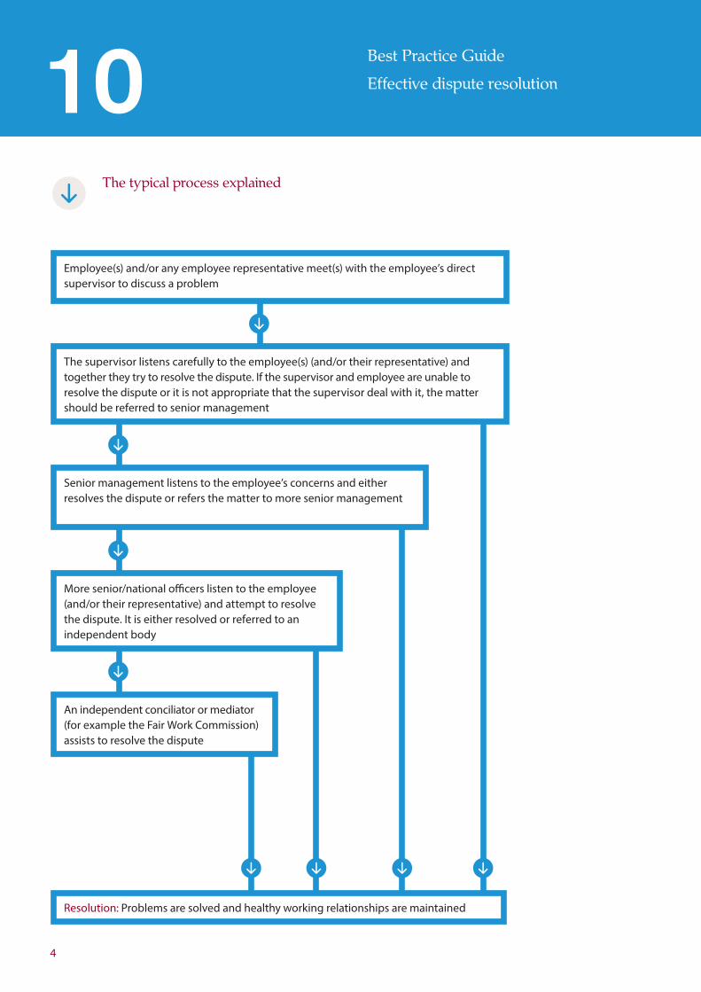
The typical process explained
Employee(s) and/or any employee representative meet(s) with the employee’s direct supervisor to discuss a problem
The supervisor listens carefully to the employee(s) (and/or their representative) and together they try to resolve the dispute. If the supervisor and employee are unable to resolve the dispute or it is not appropriate that the supervisor deal with it, the matter should be referred to senior management
Senior management listens to the employee’s concerns and either resolves the dispute or refers the matter to more senior management
More senior/national officers listen to the employee (and/or their representative) and attempt to resolve the dispute. It is either resolved or referred to an independent body
An independent conciliator or mediator (for example the Fair Work Commission) assists to resolve the dispute
Resolution: Problems are solved and healthy working relationships are maintained
4
Best Practice Guide
Effective dispute resolution
Fair Work Ombudsman 5
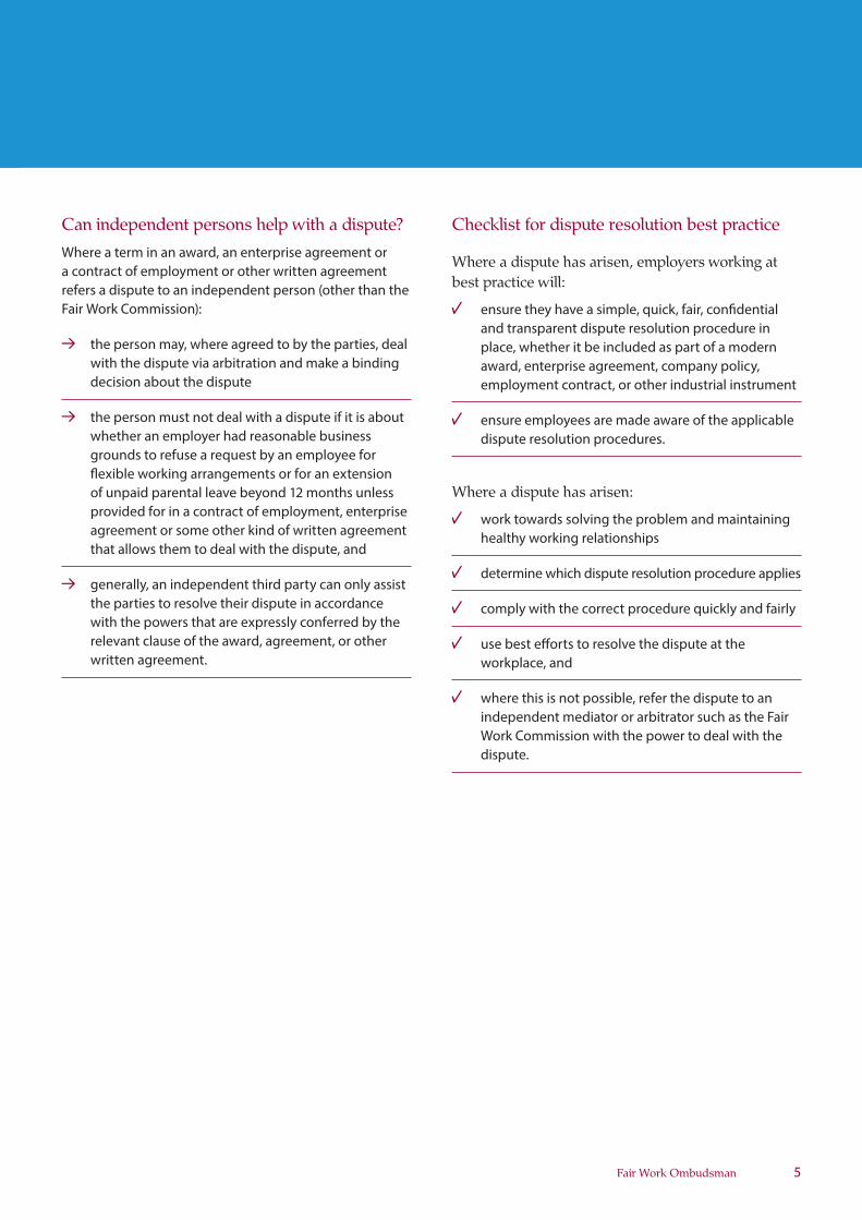
Can independent persons help with a dispute?
Where a term in an award, an enterprise agreement or a contract of employment or other written agreement refers a dispute to an independent person (other than the Fair Work Commission):
the perswith the decision
the perswhether grounds flexible of unpaiprovideagreemethat allo
generallthe partiwith the relevant written a
on may, where agreed to by the parties, deal dispute via arbitration and make a binding about the dispute
on must not deal with a dispute if it is about an employer had reasonable business to refuse a request by an employee for
working arrangements or for an extension d parental leave beyond 12 months unless d for in a contract of employment, enterprise
nt or some other kind of written agreement ws them to deal with the dispute, and
y, an independent third party can only assist es to resolve their dispute in accordance powers that are expressly conferred by the clause of the award, agreement, or other greement.
Checklist for dispute resolution best practice
Where a dispute has arisen, employers working at best practice will:
ensure tand traplace, waward, employ
ensure dispute
Where a dis
work tohealthy
determi
comply
use besworkpla
where tindepeWork Cdispute.
hey have a simple, quick, fair, confidential nsparent dispute resolution procedure in
hether it be included as part of a modern enterprise agreement, company policy, ment contract, or other industrial instrument
employees are made aware of the applicable resolution procedures.
pute has arisen:
wards solving the problem and maintaining working relationships
ne which dispute resolution procedure applies
with the correct procedure quickly and fairly
t efforts to resolve the dispute at the ce, and
his is not possible, refer the dispute to an ndent mediator or arbitrator such as the Fair ommission with the power to deal with the
Fair Work Ombudsman 13 13 94 www.fairwork.gov.au
For more information
Disclaimer
The Fair Work Ombudsman is committed to providing you with advice that you can rely on.
The information contained in this Best Practice Guide is general in nature. If you are unsure about how it applies to your situation you can call our Infoline on 13 13 94 or speak with a union, industry association or a workplace relations professional.
Produced December 2013. FWOBPG10a.02.
© Commonwealth of Australia 2013
Fair Work Ombudsman13 13 94 www.fairwork.gov.au
Fair Work Commission1300 799 675 www.fwc.gov.au
Model term for dealing with disputes for enterprise agreementsFair Work Regulations, Regulation 6.01
For more information
Acronyms used in this guide
FW Act Fair Work Act 2009
NES National Employment Standards
APPENDIX II
Road Closure Plan for blasting at Wonga Quarry
adjacent to Lowes Mount Road
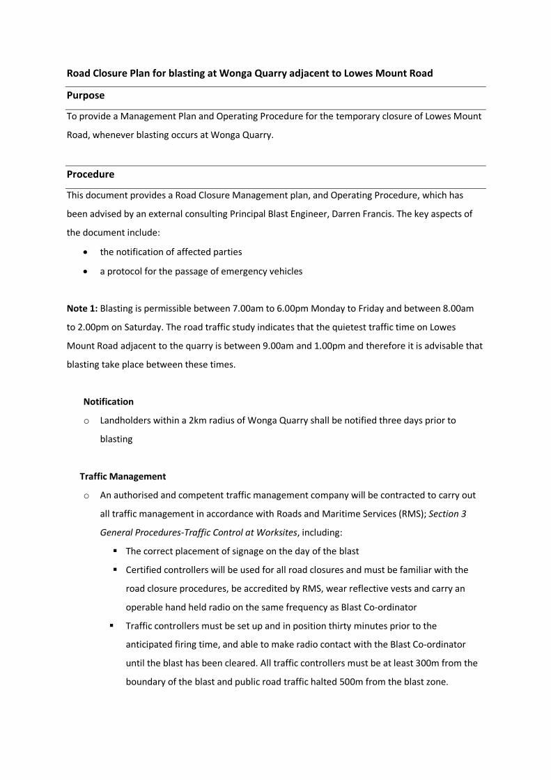
Road Closure Plan for blasting at Wonga Quarry adjacent to Lowes Mount Road
Purpose
To provide a Management Plan and Operating Procedure for the temporary closure of Lowes Mount
Road, whenever blasting occurs at Wonga Quarry.
Procedure
This document provides a Road Closure Management plan, and Operating Procedure, which has
been advised by an external consulting Principal Blast Engineer, Darren Francis. The key aspects of
the document include:
the notification of affected parties
a protocol for the passage of emergency vehicles
Note 1: Blasting is permissible between 7.00am to 6.00pm Monday to Friday and between 8.00am
to 2.00pm on Saturday. The road traffic study indicates that the quietest traffic time on Lowes
Mount Road adjacent to the quarry is between 9.00am and 1.00pm and therefore it is advisable that
blasting take place between these times.
Notification
o Landholders within a 2km radius of Wonga Quarry shall be notified three days prior to
blasting
Traffic Management
o An authorised and competent traffic management company will be contracted to carry out
all traffic management in accordance with Roads and Maritime Services (RMS); Section 3
General Procedures‐Traffic Control at Worksites, including:
The correct placement of signage on the day of the blast
Certified controllers will be used for all road closures and must be familiar with the
road closure procedures, be accredited by RMS, wear reflective vests and carry an
operable hand held radio on the same frequency as Blast Co‐ordinator
Traffic controllers must be set up and in position thirty minutes prior to the
anticipated firing time, and able to make radio contact with the Blast Co‐ordinator
until the blast has been cleared. All traffic controllers must be at least 300m from the
boundary of the blast and public road traffic halted 500m from the blast zone.
The traffic controllers shall close the road prior to blasting, when advised by the Blast
Co‐ordinator. All traffic and personnel must then be cleared from the affected area by
a competent person and the Blast Co‐ordinator advised when this has been
completed. Physical barriers should then be placed across the road to prevent access
as per the Traffic Control Plan.
All traffic must be halted for the duration of the blast. In the case of emergency traffic
refer below: Emergency Vehicle Passage
The traffic controllers shall not re‐open the road until advised by the Blast Co‐
ordinator that it is safe to do so. Prior to re‐opening, the road shall be inspected to
ensure it is in a safe and trafficable condition. Any damage, fly‐rock or other traffic
hazards shall be rectified, with personnel and ancillary equipment available on
standby for immediate road clearing purposes when deemed necessary. When the
blast has been cleared and the road inspected, normal traffic can be resumed and
signage removed.
Shot Firing Procedure
This procedure shall apply to all blasting at Wonga Quarry where fly‐rock is considered to
present a potential risk to traffic on Lowes Mount Road or when it is otherwise
considered necessary to close that road. The approximate area of affected blasting shall
be illustrated on the blast sentry plan and include a 330 metre exclusion zone. The Shot
Firer shall fire the blast according to Australian Standard’s and in accordance with other
applicable blasting and environmental procedures, with the following exceptions:
If passage of emergency vehicle is necessary
Blasting will not take place at times when adverse conditions (or other prevailing
conditions) make road closure hazardous.
All blasts will require the closure of Lowes Mount Road and will be tied up on the
day of firing and must not be left tied up overnight.
All blasts will require the closure of Lowes Mount Road and will not be tied up if
weather conditions are expected to prevent blasting within the required time
frame.
Misfires identified while Lowes Mount Road is closed will be treated as separate
blasts in order to prevent lengthy road closures.
After firing, the Blast Co‐ordinator shall advise the traffic controllers and sentries when it is
safe to check the road for damage/fly‐rock and if traffic flow can be permitted (under
supervision) prior to final clearance. Radio silence must be maintained and traffic controllers
remain in position until the blast has been cleared and the road inspected
Emergency Vehicle Passage
If traffic controllers or sentries encounter emergency vehicles (Police, Ambulance or Fire)
requiring immediate access along Lowes Mount Road, it may be necessary to abort the blast.
Traffic controllers and/or sentries must break radio silence and inform the Blast Co‐ordinator
if access is required (or has occurred) once the shot firing is in progress. If the blast can be
halted, emergency vehicles can be allowed to pass and the shot firing procedure
recommenced once the road is clear and secured.
Role Accountabilities for this document
Site supervisor Oversee the review of process and procedure Review and approve procedure Ensure a process for training of relevant personnel Complete the road closure checklist and submit required notifications Review procedure Ensure a process for training of relevant personnel
Drill and Blast Supervisor Complete the road closure checklist and submit required notifications To assist in the procedure development where required Supervise and document the provision of procedure training Ensure procedure is communicated, understood and followed by all personnel
Traffic Controller Position and remove required signage according to RTA guidelines and approved traffic control plan. Prevent access to the closed area while blasting in progress and until notified by the Blast Co‐ordinator
Sentries Prevent access to the closed area while blasting in progress and until the blast has been cleared
Blast Co‐ordinator To assist in the procedure development where required Ensure procedure is followed and blasting is carried out in accordance with shot firing and road closure procedures. Remain in contact with the traffic controllers and sentries during the shot firing process Report any deficiencies with the procedure
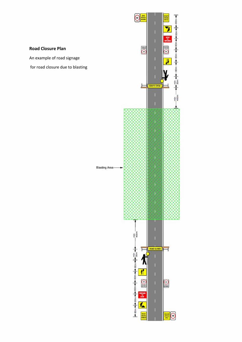
Road Closure Plan
An example of road signage
for road closure due to blasting
APPENDIX III
Example of Site Induction Form
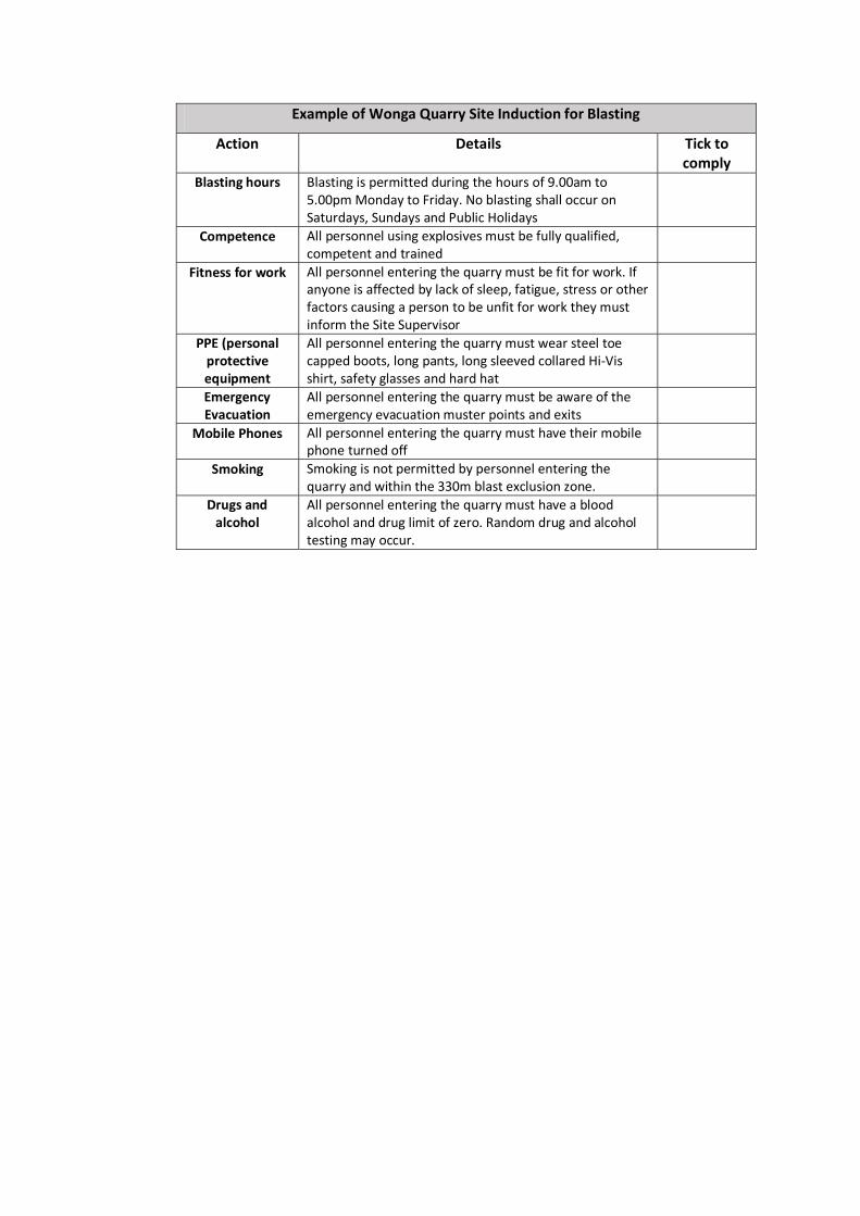
Example of Wonga Quarry Site Induction for Blasting
Action Details Tick to comply
Blasting hours Blasting is permitted during the hours of 9.00am to 5.00pm Monday to Friday. No blasting shall occur on Saturdays, Sundays and Public Holidays
Competence All personnel using explosives must be fully qualified, competent and trained
Fitness for work All personnel entering the quarry must be fit for work. If anyone is affected by lack of sleep, fatigue, stress or other factors causing a person to be unfit for work they must inform the Site Supervisor
PPE (personal protective equipment
All personnel entering the quarry must wear steel toe capped boots, long pants, long sleeved collared Hi‐Vis shirt, safety glasses and hard hat
Emergency Evacuation
All personnel entering the quarry must be aware of the emergency evacuation muster points and exits
Mobile Phones All personnel entering the quarry must have their mobile phone turned off
Smoking Smoking is not permitted by personnel entering the quarry and within the 330m blast exclusion zone.
Drugs and alcohol
All personnel entering the quarry must have a blood alcohol and drug limit of zero. Random drug and alcohol testing may occur.
APPENDIX IV
Technical report from
Darren Francis, Principal Engineer
Nitrotek Consulting
Nitrotek Consulting Page 1 of 9
NITROTEK CONSULTINGBlasting Specialists
Mining ‐Civil ‐Agriculture
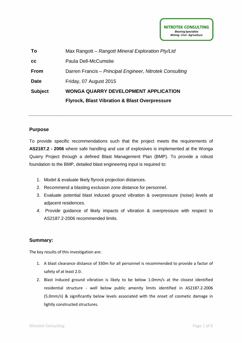
To Max Rangott – Rangott Mineral Exploration Pty/Ltd
cc Paula Dell-McCumstie
From Darren Francis – Principal Engineer, Nitrotek Consulting
Date Friday, 07 August 2015
Subject WONGA QUARRY DEVELOPMENT APPLICATION
Flyrock, Blast Vibration & Blast Overpressure
Purpose
To provide specific recommendations such that the project meets the requirements of
AS2187.2 - 2006 where safe handling and use of explosives is implemented at the Wonga
Quarry Project through a defined Blast Management Plan (BMP). To provide a robust
foundation to the BMP, detailed blast engineering input is required to:
1. Model & evaluate likely flyrock projection distances.
2. Recommend a blasting exclusion zone distance for personnel.
3. Evaluate potential blast induced ground vibration & overpressure (noise) levels at
adjacent residences.
4. Provide guidance of likely impacts of vibration & overpressure with respect to
AS2187.2-2006 recommended limits.
Summary:
The key results of this investigation are:
1. A blast clearance distance of 330m for all personnel is recommended to provide a factor of
safety of at least 2.0.
2. Blast induced ground vibration is likely to be below 1.0mm/s at the closest identified
residential structure ‐ well below public amenity limits identified in AS2187.2‐2006
(5.0mm/s) & significantly below levels associated with the onset of cosmetic damage in
lightly constructed structures.
Nitrotek Consulting Page 2 of 9
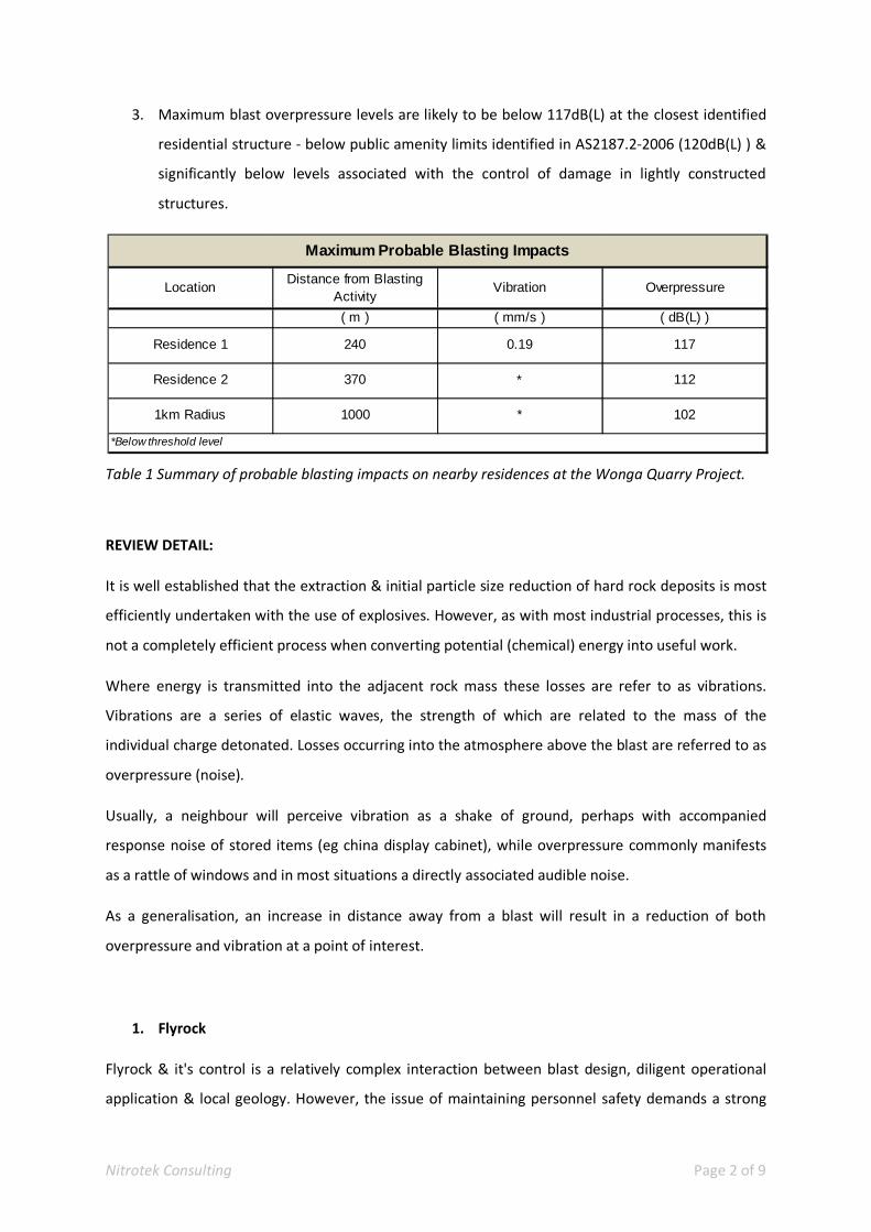
3. Maximum blast overpressure levels are likely to be below 117dB(L) at the closest identified
residential structure ‐ below public amenity limits identified in AS2187.2‐2006 (120dB(L) ) &
significantly below levels associated with the control of damage in lightly constructed
structures.
Table 1 Summary of probable blasting impacts on nearby residences at the Wonga Quarry Project.
REVIEW DETAIL:
It is well established that the extraction & initial particle size reduction of hard rock deposits is most
efficiently undertaken with the use of explosives. However, as with most industrial processes, this is
not a completely efficient process when converting potential (chemical) energy into useful work.
Where energy is transmitted into the adjacent rock mass these losses are refer to as vibrations.
Vibrations are a series of elastic waves, the strength of which are related to the mass of the
individual charge detonated. Losses occurring into the atmosphere above the blast are referred to as
overpressure (noise).
Usually, a neighbour will perceive vibration as a shake of ground, perhaps with accompanied
response noise of stored items (eg china display cabinet), while overpressure commonly manifests
as a rattle of windows and in most situations a directly associated audible noise.
As a generalisation, an increase in distance away from a blast will result in a reduction of both
overpressure and vibration at a point of interest.
1. Flyrock
Flyrock & it's control is a relatively complex interaction between blast design, diligent operational
application & local geology. However, the issue of maintaining personnel safety demands a strong
LocationDistance from Blasting
ActivityVibration Overpressure
( m ) ( mm/s ) ( dB(L) )
Residence 1 240 0.19 117
Residence 2 370 * 112
1km Radius 1000 * 102
Maximum Probable Blasting Impacts
*Below threshold level
Nitrotek Consulting Page 3 of 9
engineering basis to ensure safety under all blasting conditions at all times. Experience has shown
that flyrock projection distance estimations & subsequent selection of appropriate clearance zones
must be carefully assessed with as complete knowledge as possible of each individual blasting
application.
Best practice blasting incorporates a level of redundancy within the blast design to ensure an
acceptable factor of safety is maintained even in the event of unintended unknown deviations
during application of the design (such as shorter stemming lengths).
Various studies have sought to generate predictive equations for maximum flyrock range & generally
are based on consideration of:
Rock density
Blast hole diameter
Explosive density
Confinement levels
Particle size achieving maximum range
The equations developed combined with other known equations of motion allow the determination
of practical limits for any charge configuration, blast hole size, rock type & shape factor (ratio of
surface area to volume). More recently, improved realistic particle motion has been achieved by
incorporating the additional influence of air resistance for estimated particle trajectories.
The calculation adopted for the Wonga Quarry site combines all of the points mentioned above into
a succinct form:
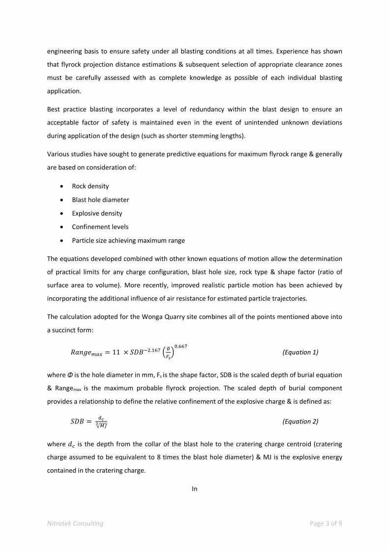
11 . ∅ . (Equation 1)
where Φ is the hole diameter in mm, Fs is the shape factor, SDB is the scaled depth of burial equation
& Rangemax is the maximum probable flyrock projection. The scaled depth of burial component
provides a relationship to define the relative confinement of the explosive charge & is defined as:
√
(Equation 2)
where is the depth from the collar of the blast hole to the cratering charge centroid (cratering
charge assumed to be equivalent to 8 times the blast hole diameter) & MJ is the explosive energy
contained in the cratering charge.
In
Nitrotek Consulting Page 4 of 9
Individual blast to produce 5 years supply of material
Intact rock strength in the order of 110MPa to 140Mpa
Intact rock ‐ Young's Modulus = 62GPa
Intact rock ‐ Poisson's Ratio = 0.32
Working face height = 4.0m
Blast hole diameter = 89mm
Bulk explosive density = 1.10g/cc
The
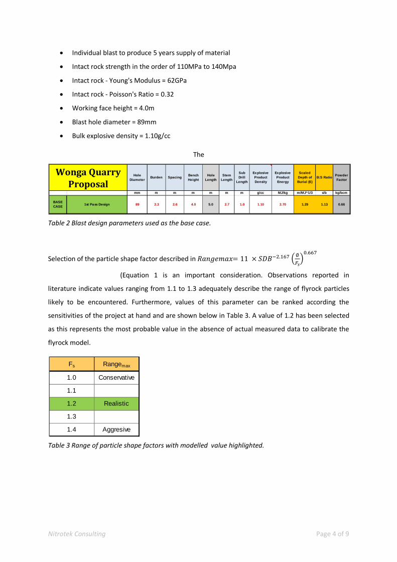
Table 2 Blast design parameters used as the base case.
Selection of the particle shape factor described in 11 . ∅ .
(Equation 1 is an important consideration. Observations reported in
literature indicate values ranging from 1.1 to 1.3 adequately describe the range of flyrock particles
likely to be encountered. Furthermore, values of this parameter can be ranked according the
sensitivities of the project at hand and are shown below in Table 3. A value of 1.2 has been selected
as this represents the most probable value in the absence of actual measured data to calibrate the
flyrock model.
Table 3 Range of particle shape factors with modelled value highlighted.
Hole Diameter
Burden SpacingBench Height
Hole Length
Stem Length
Sub Drill
Length
Explosive Product Density
Explosive Product Energy
Scaled Depth of Burial (E)
B:S RatioPowder Factor
mm m m m m m m g/cc MJ/kg m/MJ^1/3 s/b kg/bcm
BASE CASE
1st Pass Design 89 2.3 2.6 4.0 5.0 2.7 1.0 1.10 2.70 1.29 1.13 0.66
WongaQuarryProposal
Fs Rangemax
1.0 Conservative
1.1
1.2 Realistic
1.3
1.4 Aggresive
Nitrotek Consulting Page 5 of 9
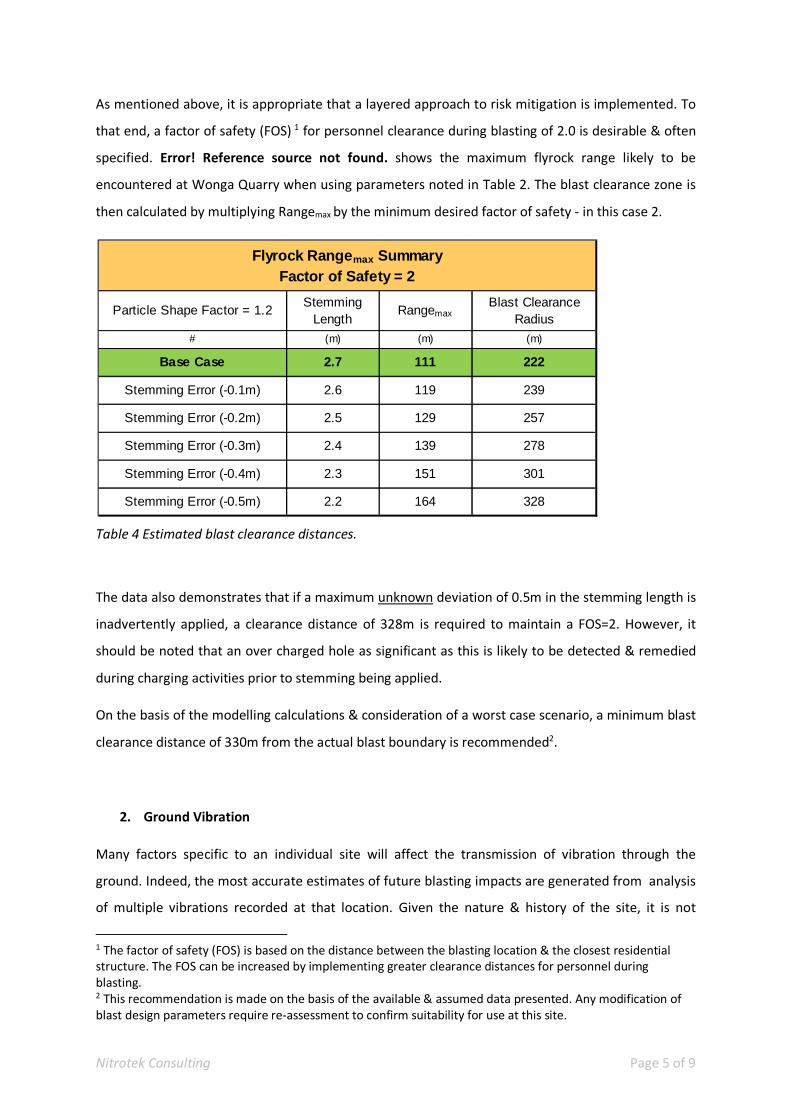
As mentioned above, it is appropriate that a layered approach to risk mitigation is implemented. To
that end, a factor of safety (FOS) 1 for personnel clearance during blasting of 2.0 is desirable & often
specified. Error! Reference source not found. shows the maximum flyrock range likely to be
encountered at Wonga Quarry when using parameters noted in Table 2. The blast clearance zone is
then calculated by multiplying Rangemax by the minimum desired factor of safety ‐ in this case 2.
Table 4 Estimated blast clearance distances.
The data also demonstrates that if a maximum unknown deviation of 0.5m in the stemming length is
inadvertently applied, a clearance distance of 328m is required to maintain a FOS=2. However, it
should be noted that an over charged hole as significant as this is likely to be detected & remedied
during charging activities prior to stemming being applied.
On the basis of the modelling calculations & consideration of a worst case scenario, a minimum blast
clearance distance of 330m from the actual blast boundary is recommended2.
2. Ground Vibration
Many factors specific to an individual site will affect the transmission of vibration through the
ground. Indeed, the most accurate estimates of future blasting impacts are generated from analysis
of multiple vibrations recorded at that location. Given the nature & history of the site, it is not
1 The factor of safety (FOS) is based on the distance between the blasting location & the closest residential structure. The FOS can be increased by implementing greater clearance distances for personnel during blasting. 2 This recommendation is made on the basis of the available & assumed data presented. Any modification of blast design parameters require re‐assessment to confirm suitability for use at this site.
Particle Shape Factor = 1.2Stemming
LengthRangemax
Blast Clearance Radius
# (m) (m) (m)
Base Case 2.7 111 222
Stemming Error (-0.1m) 2.6 119 239
Stemming Error (-0.2m) 2.5 129 257
Stemming Error (-0.3m) 2.4 139 278
Stemming Error (-0.4m) 2.3 151 301
Stemming Error (-0.5m) 2.2 164 328
Flyrock Rangemax SummaryFactor of Safety = 2
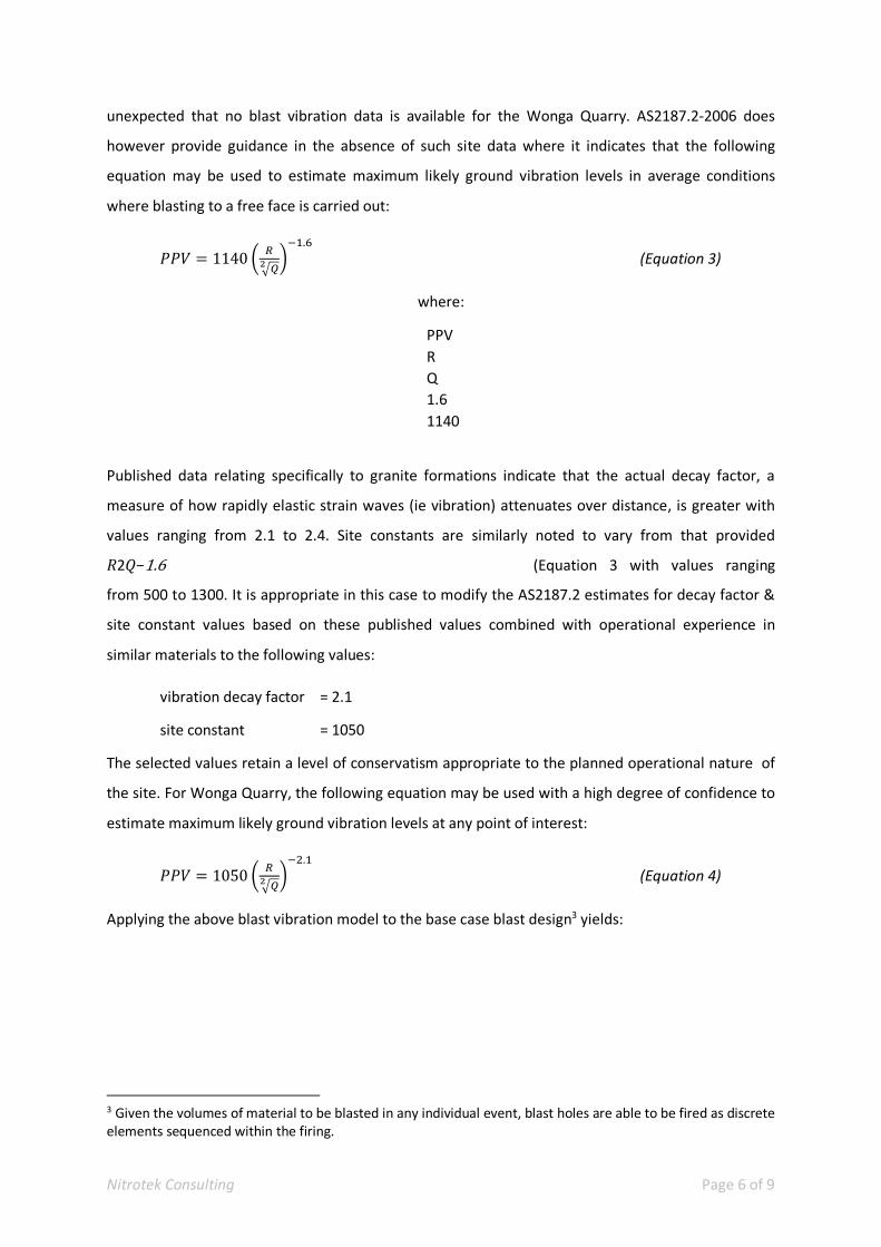
Nitrotek Consulting Page 6 of 9
unexpected that no blast vibration data is available for the Wonga Quarry. AS2187.2‐2006 does
however provide guidance in the absence of such site data where it indicates that the following
equation may be used to estimate maximum likely ground vibration levels in average conditions
where blasting to a free face is carried out:
1140.
(Equation 3)
where:
PPV
R
Q
1.6
1140
Published data relating specifically to granite formations indicate that the actual decay factor, a
measure of how rapidly elastic strain waves (ie vibration) attenuates over distance, is greater with
values ranging from 2.1 to 2.4. Site constants are similarly noted to vary from that provided
2 −1.6 (Equation 3 with values ranging
from 500 to 1300. It is appropriate in this case to modify the AS2187.2 estimates for decay factor &
site constant values based on these published values combined with operational experience in
similar materials to the following values:
vibration decay factor = 2.1
site constant = 1050
The selected values retain a level of conservatism appropriate to the planned operational nature of
the site. For Wonga Quarry, the following equation may be used with a high degree of confidence to
estimate maximum likely ground vibration levels at any point of interest:
1050.
(Equation 4)
Applying the above blast vibration model to the base case blast design3 yields:
3 Given the volumes of material to be blasted in any individual event, blast holes are able to be fired as discrete elements sequenced within the firing.
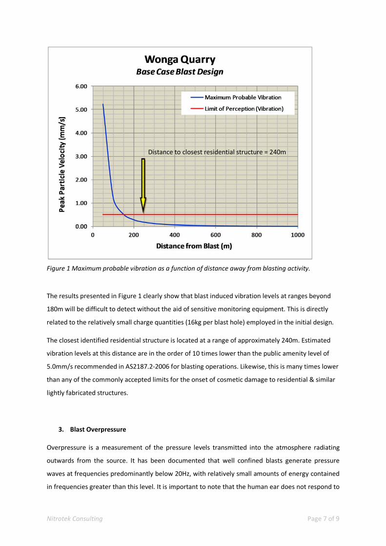
Nitrotek Consulting Page 7 of 9
Figure 1 Maximum probable vibration as a function of distance away from blasting activity.
The results presented in Figure 1 clearly show that blast induced vibration levels at ranges beyond
180m will be difficult to detect without the aid of sensitive monitoring equipment. This is directly
related to the relatively small charge quantities (16kg per blast hole) employed in the initial design.
The closest identified residential structure is located at a range of approximately 240m. Estimated
vibration levels at this distance are in the order of 10 times lower than the public amenity level of
5.0mm/s recommended in AS2187.2‐2006 for blasting operations. Likewise, this is many times lower
than any of the commonly accepted limits for the onset of cosmetic damage to residential & similar
lightly fabricated structures.
3. Blast Overpressure
Overpressure is a measurement of the pressure levels transmitted into the atmosphere radiating
outwards from the source. It has been documented that well confined blasts generate pressure
waves at frequencies predominantly below 20Hz, with relatively small amounts of energy contained
in frequencies greater than this level. It is important to note that the human ear does not respond to
Distance to closest residential structure = 240m
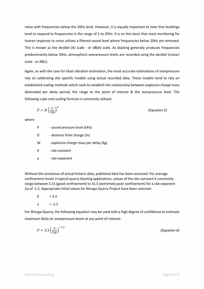
Nitrotek Consulting Page 8 of 9
noise with frequencies below the 20Hz level. However, it is equally important to note that buildings
tend to respond to frequencies in the range of 2 to 20Hz. It is on this basis that most monitoring for
human response to noise utilises a filtered sound level where frequencies below 20Hz are removed.
This is known as the decibel (A) scale ‐ or dB(A) scale. As blasting generally produces frequencies
predominantly below 20Hz, atmospheric overpressure levels are recorded using the decibel (Linear)
scale ‐ or dB(L).
Again, as with the case for blast vibration estimation, the most accurate estimations of overpressure
rely on calibrating site specific models using actual recorded data. These models tend to rely on
established scaling methods which seek to establish the relationship between explosive charge mass
detonated per delay period, the range to the point of interest & the overpressure level. The
following cube root scaling formula is commonly utilised:
√
(Equation 5)
where
P ‐ sound pressure level (kPa)
D ‐ distance from charge (m)
W ‐ explosive charge mass per delay (kg)
K ‐ site constant
a ‐ site exponent
Without the assistance of actual historic data, published data has been accessed. For average
confinement levels in typical quarry blasting applications, values of the site constant K commonly
range between 3.15 (good confinement) to 31.5 (extremely poor confinement) for a site exponent
(a) of ‐1.2. Appropriate initial values for Wonga Quarry Project have been selected:
K = 3.3
a = ‐1.2
For Wonga Quarry, the following equation may be used with a high degree of confidence to estimate
maximum likely air overpressure levels at any point of interest:
3.3√
. (Equation 6)
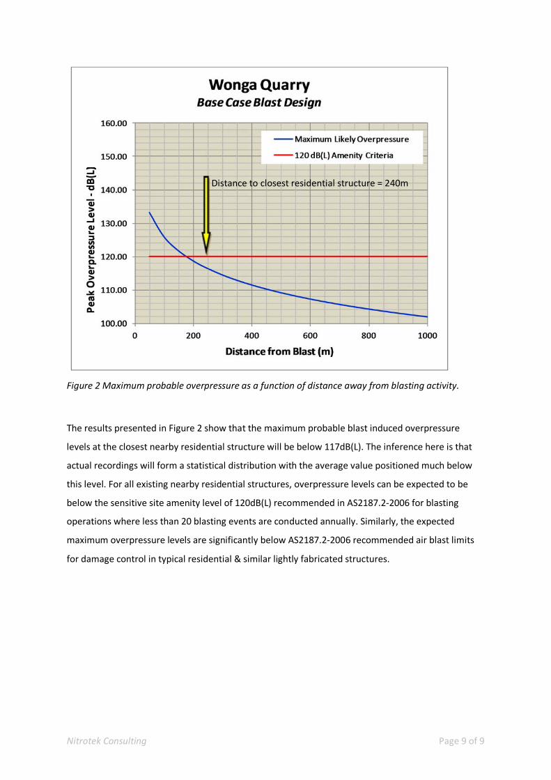
Nitrotek Consulting Page 9 of 9
Figure 2 Maximum probable overpressure as a function of distance away from blasting activity.
The results presented in Figure 2 show that the maximum probable blast induced overpressure
levels at the closest nearby residential structure will be below 117dB(L). The inference here is that
actual recordings will form a statistical distribution with the average value positioned much below
this level. For all existing nearby residential structures, overpressure levels can be expected to be
below the sensitive site amenity level of 120dB(L) recommended in AS2187.2‐2006 for blasting
operations where less than 20 blasting events are conducted annually. Similarly, the expected
maximum overpressure levels are significantly below AS2187.2‐2006 recommended air blast limits
for damage control in typical residential & similar lightly fabricated structures.
Distance to closest residential structure = 240m
![[2003] ATP 24 AMP Shopping Centre Trust 02 - Australian … · AMP Shopping Centre Trust 02 ... Mutual Pools and Staff Pty Ltd v The Commonwealth (1994) ... Tracy v Mandalay Pty Ltd](https://img.pdfslide.tips/doc/110x75/5acadb6a7f8b9a5d718e729e/2003-atp-24-amp-shopping-centre-trust-02-australian-shopping-centre-trust.jpg)
![A Daily Bulletin listing Decisions of Superior Courts of ......Aug 18, 2008 · Chiropedic Bedding Pty Ltd v Radburg Pty Ltd [2008] FCAFC 142 Full Federal Court of Australia French,](https://img.pdfslide.tips/doc/110x75/5f02c2a27e708231d405e040/a-daily-bulletin-listing-decisions-of-superior-courts-of-aug-18-2008-.jpg)