Embed Size (px)
Citation preview
DEIF A/S · Frisenborgvej 33 · DK-7800 Skive · Tel.: +45 9614 9614 · Fax: +45 9614 9615 · [email protected] · www.deif.com
DEIF A/S · Frisenborgvej 33 · DK-7800 Skive · Tel.: +45 9614 9614 · Fax: +45 9614 9615 · [email protected] · www.deif.com
DEIF A/S · Frisenborgvej 33 · DK-7800 Skive · Tel.: +45 9614 9614 · Fax: +45 9614 9615 · [email protected] · www.deif.com
DATA SHEET
Automatic Genset Controller, AGC-3● Operation modes● Engine control● Generator protection (ANSI)● Display● Mains/busbar protection (ANSI)● M-Logic (Micro PLC)● General
Document no.: 4921240396DSW version: 3.6x.x or later
1. Application information1.1. General information................................................................................................................................3
1.1.1. Application.....................................................................................................................................31.1.2. Test................................................................................................................................................41.1.3. Setup.............................................................................................................................................41.1.4. Options..........................................................................................................................................41.1.5. Unit definitions...............................................................................................................................51.1.6. M-Logic (Micro PLC)......................................................................................................................51.1.7. Single line application diagrams....................................................................................................51.1.8. Principle diagrams.........................................................................................................................7
1.2. Power management applications (option G4/G5/G8).............................................................................71.2.1. Description.....................................................................................................................................71.2.2. Application.....................................................................................................................................81.2.3. Configuration.................................................................................................................................81.2.4. Load management ........................................................................................................................91.2.5. Load-dependent operation.............................................................................................................91.2.6. Priority selection............................................................................................................................91.2.7. Redundant AGC mains and CANbus..........................................................................................101.2.8. Optional power management applications ..................................................................................11
2. Optional functionality2.1. Display layouts.....................................................................................................................................13
2.1.1. Option Y1 ....................................................................................................................................132.1.2. Option Y3 ....................................................................................................................................132.1.3. Option Y4.....................................................................................................................................132.1.4. Option Y5.....................................................................................................................................142.1.5. Option X3 ....................................................................................................................................142.1.6. Option X4 ....................................................................................................................................14
2.2. Available options..................................................................................................................................152.2.1. Available variants ........................................................................................................................152.2.2. Available software options...........................................................................................................162.2.3. Available accessories .................................................................................................................202.2.4. Hardware options ........................................................................................................................21
3. Technical information3.1. Specifications and dimensions.............................................................................................................24
3.1.1. Technical specifications ..............................................................................................................243.1.2. Unit dimensions in mm (inches)...................................................................................................28
4. Ordering information4.1. Order specifications and disclaimer.....................................................................................................29
4.1.1. Order specifications.....................................................................................................................294.1.2. Disclaimer....................................................................................................................................29
AGC-3 data sheet 4921240396 UK
DEIF A/S Page 2 of 29
1. Application information1.1 General information
1.1.1 ApplicationThe Automatic Gen-set Controller is a microprocessor-based control unit containing all necessary functionsfor protection and control of a gen-set. It contains all necessary 3-phase measuring circuits, and all valuesand alarms are presented on the LCD display.
The AGC is a compact all-in-one unit designed for the following applications:
● Automatic mains failure● Island operation● Fixed power/base load● Peak shaving● Load takeover● Mains power export (fixed power to mains)● Remote maintenance
Optional applications:
● Multiple gen-sets, load sharing● Power management (island operation)● Power management (island operation, split bus)● Power management (island operation, ring bus)● Power management (parallel with mains)● Power management (parallel with mains, split bus)● Power management (parallel with mains, ring bus)
The AGC can operate in automatic mains failure mode as a secondary mode regardless of thetype of application - except the island applications.
The display is separate and can be installed directly on the main unit or in the front of the switchboard door(requires option J1, J2 or J6 - display cable). Additional displays can be installed within 200 m.
The AGC is supplied with an engine interface I/O card with separate power supply and processor. The card isequipped with the following I/Os:
AGC-3 data sheet 4921240396 UK Application information
DEIF A/S Page 3 of 29
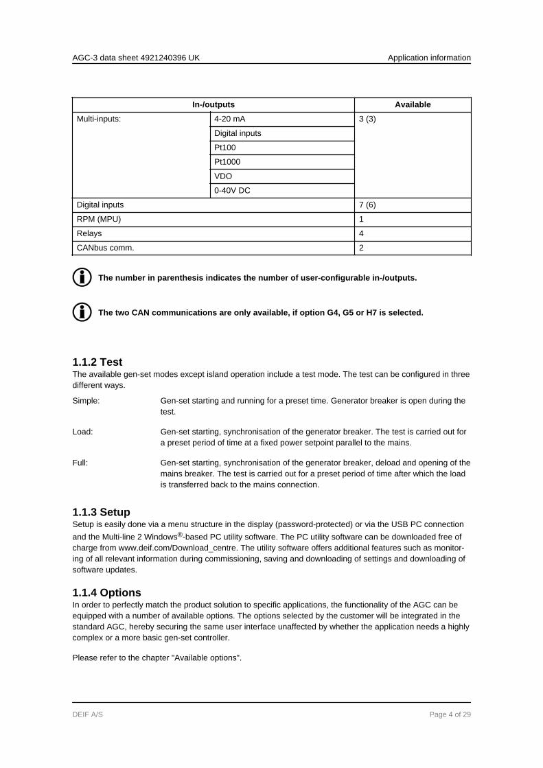
In-/outputs Available
Multi-inputs: 4-20 mA 3 (3)
Digital inputs
Pt100
Pt1000
VDO
0-40V DC
Digital inputs 7 (6)
RPM (MPU) 1
Relays 4
CANbus comm. 2
The number in parenthesis indicates the number of user-configurable in-/outputs.
The two CAN communications are only available, if option G4, G5 or H7 is selected.
1.1.2 TestThe available gen-set modes except island operation include a test mode. The test can be configured in threedifferent ways.
Gen-set starting and running for a preset time. Generator breaker is open during thetest.
Simple:
Gen-set starting, synchronisation of the generator breaker. The test is carried out fora preset period of time at a fixed power setpoint parallel to the mains.
Load:
Gen-set starting, synchronisation of the generator breaker, deload and opening of themains breaker. The test is carried out for a preset period of time after which the loadis transferred back to the mains connection.
Full:
1.1.3 SetupSetup is easily done via a menu structure in the display (password-protected) or via the USB PC connectionand the Multi-line 2 Windows®-based PC utility software. The PC utility software can be downloaded free ofcharge from www.deif.com/Download_centre. The utility software offers additional features such as monitor-ing of all relevant information during commissioning, saving and downloading of settings and downloading ofsoftware updates.
1.1.4 OptionsIn order to perfectly match the product solution to specific applications, the functionality of the AGC can beequipped with a number of available options. The options selected by the customer will be integrated in thestandard AGC, hereby securing the same user interface unaffected by whether the application needs a highlycomplex or a more basic gen-set controller.
Please refer to the chapter "Available options".
AGC-3 data sheet 4921240396 UK Application information
DEIF A/S Page 4 of 29
1.1.5 Unit definitionsThe standard control unit designed for a number of applications (1-9). An extensivelist of hardware and software options is available for the AGC.
AGC:
A power management control unit used in the parallel with mains power managementapplication (6-9). Several options are available for the AGC mains.
AGC mains:
A power management control unit used in the power management application to splitthe busbar (8). Several options are available for the AGC BTB.
AGC BTB:
1.1.6 M-Logic (Micro PLC)This configuration tool is part of the PC utility software which is free of charge. With this tool, it is possible tocustomise the application to your needs. It is possible to dedicate specific functions or logical conditions todifferent inputs and outputs.
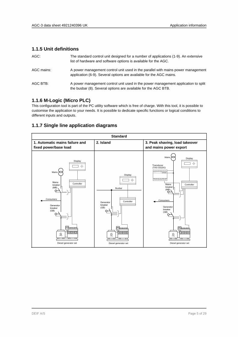
1.1.7 Single line application diagrams
Standard
1. Automatic mains failure andfixed power/base load
2. Island 3. Peak shaving, load takeoverand mains power export
G
Generator
breaker
(GB)
Mains
breaker
(MB)
Mains
Diesel generator set
Consumers
Controller
Display
G
Generator
breaker
(GB)
Diesel generator set
Busbar
Controller
Display
G
Generator
breaker
(GB)
Mains
breaker
(MB)
Mains
Diesel generator set
Consumers
Transducer(TAS-331DG)
Controller
Display
AGC-3 data sheet 4921240396 UK Application information
DEIF A/S Page 5 of 29
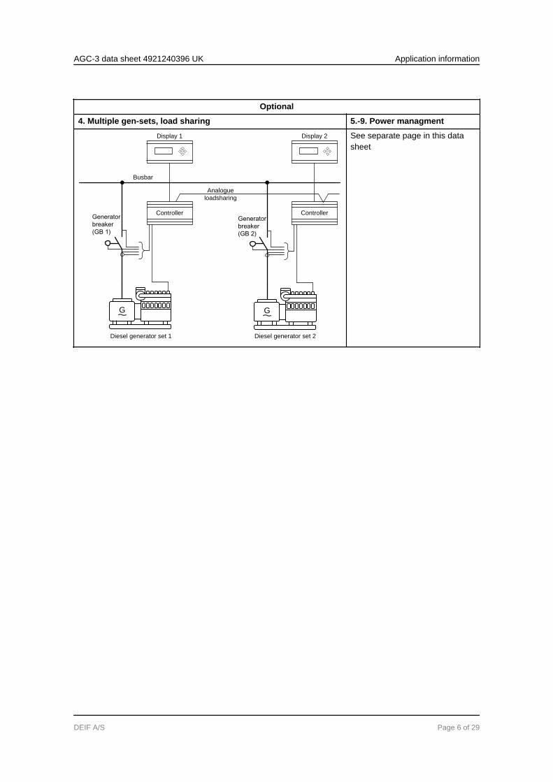
Optional
4. Multiple gen-sets, load sharing 5.-9. Power managment
G
Generator
breaker
(GB 1)
Diesel generator set 1
Busbar
G
Generator
breaker
(GB 2)
Diesel generator set 2
Analogue
loadsharing
Controller
Display 1
Controller
Display 2 See separate page in this datasheet
AGC-3 data sheet 4921240396 UK Application information
DEIF A/S Page 6 of 29
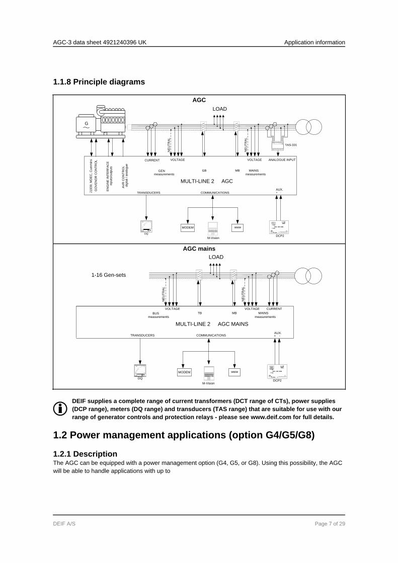
1.1.8 Principle diagrams
AGCLOAD
NE
UT
RA
L
NE
UT
RA
L
MAINSGBGEN
MULTI-LINE 2 AGC
measurements
MB
GO
VE
NO
R C
ON
TR
OL
EN
GIN
E IN
TE
RF
AC
E
AV
R C
ON
TR
OL
inp
uts
/ou
tpu
ts
dig
ita
l / a
na
log
ue
J1
93
9, M
DE
C, C
um
min
s CURRENT VOLTAGE VOLTAGE
measurements
65
50
Hz
45
TRANSDUCERSAUX.+ -COMMUNICATIONS
MODEM www
DQ
TAS-331
ANALOGUE INPUT
M-Vision
G
-+Before opening the cover wait about 3 min.
Pay attention to operating instructions.to ensure the dischage of the capacitors.
DCP-2 1205 12V/5A
Power
Output
Adj.
11,8...30,8VDC
115/230V AC
DCP2
AGC mainsLOAD
NE
UT
RA
L
NE
UT
RA
L
MAINSTBBUS
MULTI-LINE 2 AGC MAINS
measurements
MB
VOLTAGE VOLTAGE
measurements
65
50
Hz
45
TRANSDUCERSAUX.+ -COMMUNICATIONS
MODEM www
DQ
CURRENT
M-Vision
-+Before opening the cover wait about 3 min.
Pay attention to operating instructions.to ensure the dischage of the capacitors.
DCP-2 1205 12V/5A
Power
Output
Adj.
11,8...30,8VDC
115/230V AC
DCP2
1-16 Gen-sets
DEIF supplies a complete range of current transformers (DCT range of CTs), power supplies(DCP range), meters (DQ range) and transducers (TAS range) that are suitable for use with ourrange of generator controls and protection relays - please see www.deif.com for full details.
1.2 Power management applications (option G4/G5/G8)
1.2.1 DescriptionThe AGC can be equipped with a power management option (G4, G5, or G8). Using this possibility, the AGCwill be able to handle applications with up to
AGC-3 data sheet 4921240396 UK Application information
DEIF A/S Page 7 of 29
● 16 mains incoming● 16 mains breakers● 16 tie breakers● 8 bus tie breakers● 16 generators (256 on request)● 16 generators● 16 generator breakers
The basic functions are:
● All 56 breakers can be synchronised by choice● Load-dependent start/stop operation● Priority selection of gen-sets● Priority selection of mains● Redundant communication between the controllers● Plant divided into sections for individual functionality● Selectable mains priority and parallel operation● The plant mains failure sequence can call for support on local plant sections● Load management● Quick setup/broadcast● Asymmetric load sharing● CAN flags● Droop frequency/voltage● Heavy consumer (HC)● Non-essential load (NEL)/load shedding● Secured mode● Base load● Multi-master system
In a multi-master system, all vital data is broadcasted from all units to all units, giving all units knowledge oftheir own position in the application. This philosophy makes the application immune to a failing master con-troller.
1.2.2 ApplicationThe plant modes supported by the power management options are:
● Automatic mains failure/ATS● Island operation● Fixed power/base load● Peak shaving● Load takeover● Mains power export (fixed power to mains)
The plant modes are configurable, and it is possible to change the plant mode on the fly, both in single gen-set and in power management applications.
The plant can be divided into sections by several bus tie breakers, making it possible to run different plantmodes in each section.
1.2.3 ConfigurationThe setup of the application is easily configured using a computer and the DEIF PC utility software.
AGC-3 data sheet 4921240396 UK Application information
DEIF A/S Page 8 of 29
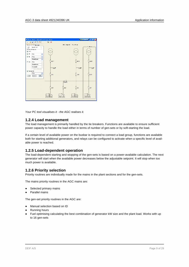
Your PC tool visualises it - the AGC realises it.
1.2.4 Load managementThe load management is primarily handled by the tie breakers. Functions are available to ensure sufficientpower capacity to handle the load either in terms of number of gen-sets or by soft-starting the load.
If a certain level of available power on the busbar is required to connect a load group, functions are availableboth for starting additional generators, and relays can be configured to activate when a specific level of avail-able power is reached.
1.2.5 Load-dependent operationThe load-dependent starting and stopping of the gen-sets is based on a power-available calculation. The nextgenerator will start when the available power decreases below the adjustable setpoint. It will stop when toomuch power is available.
1.2.6 Priority selectionPriority routines are individually made for the mains in the plant sections and for the gen-sets.
The mains priority routines in the AGC mains are:
● Selected primary mains● Parallel mains
The gen-set priority routines in the AGC are:
● Manual selection based on ID● Running hours● Fuel optimising calculating the best combination of generator kW size and the plant load. Works with up
to 16 gen-sets
AGC-3 data sheet 4921240396 UK Application information
DEIF A/S Page 9 of 29

1.2.7 Redundant AGC mains and CANbusIn emergency systems requiring extra operation reliability, redundant AGC mains units and redundant CAN-bus communication lines can be used to provide back-up.
Redundant AGC mains units are only supported in the application: Dual mains (7).
AGC-3 data sheet 4921240396 UK Application information
DEIF A/S Page 10 of 29
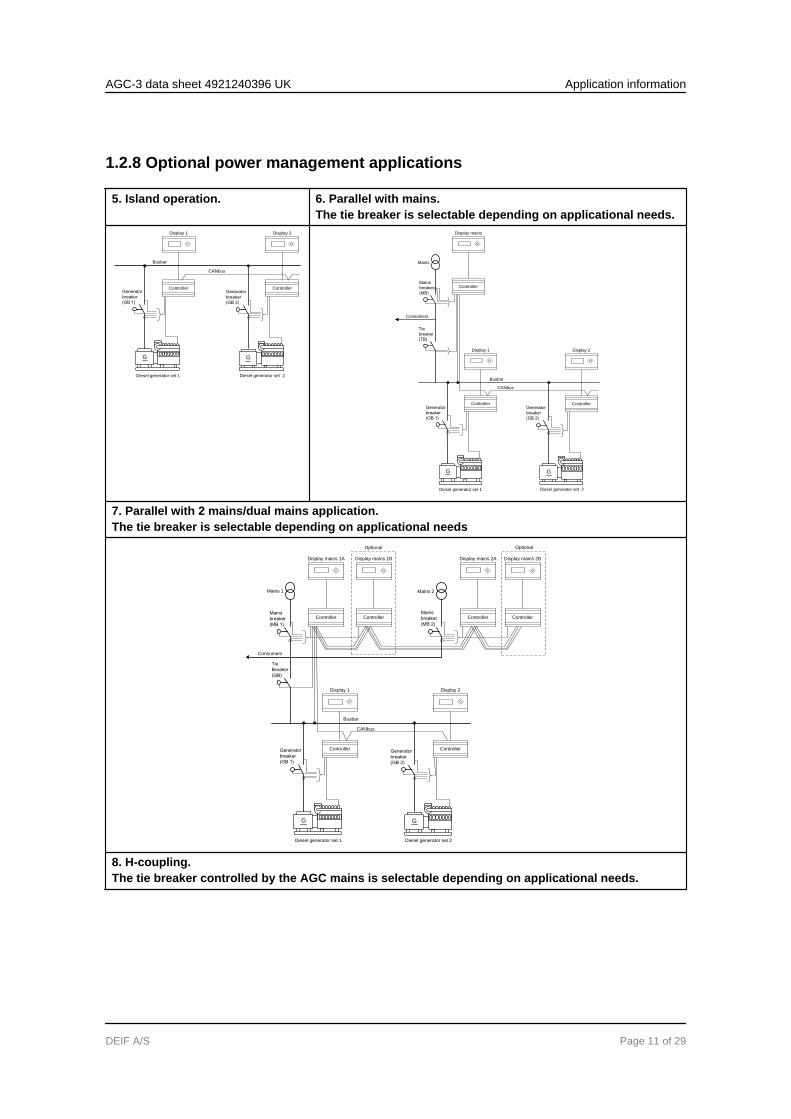
1.2.8 Optional power management applications
5. Island operation. 6. Parallel with mains.The tie breaker is selectable depending on applicational needs.
G
Generator
breaker
(GB 1)
Diesel generator set 1
Busbar
G
Generator
breaker
(GB 2)
Diesel generator set 2
CANbus
Controller
Display 1
Controller
Display 2
G
Generator
breaker
(GB 1)
Diesel generator set 1
Busbar
G
Generator
breaker
(GB 2)
Diesel generator set 2
CANbus
Tie
breaker
(TB)
Mains
breaker
(MB)
Mains
Consumers
Controller
Display 1
Controller
Display 2
Controller
Display mains
7. Parallel with 2 mains/dual mains application.The tie breaker is selectable depending on applicational needs
G
Generator
breaker
(GB 1)
Diesel generator set 1
Busbar
G
Generator
breaker
(GB 2)
Diesel generator set 2
CANbus
Tie
Breaker
(GB)
Mains
breaker
(MB 1)
Mains 1
Consumers
Mains
breaker
(MB 2)
Mains 2
Optional Optional
Controller
Display 1
Controller
Display 2
Controller
Display mains 1B
Controller
Display mains 2A
Controller
Display mains 2B
Controller
Display mains 1A
8. H-coupling.The tie breaker controlled by the AGC mains is selectable depending on applicational needs.
AGC-3 data sheet 4921240396 UK Application information
DEIF A/S Page 11 of 29
G
Generator
breaker
(GB 1)
Diesel generator set 1
Busbar
G
Generator
breaker
(GB 2)
Diesel generator set 2
CANbus
Tie
breaker
(TB 17)
Mains
breaker
(MB 17)
Mains 17
Consumers
BTB 33
G
Generator
breaker
(GB 3)
Diesel generator set 3
BUSBAR
G
Generator
breaker
(GB 4)
Diesel generator set 4
CANBUS
Tie
breaker
TB 18)
Mains
breaker
(MB 18)
Mains 18
Consumers
Controller
Display 1
Controller
Display 2
Controller
Display 3
Controller
Display BTB 33
Controller
Display 4
Controller
Display mains 17
Controller
Display mains 18
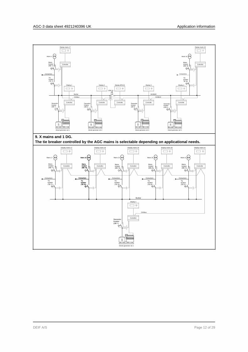
9. X mains and 1 DG.The tie breaker controlled by the AGC mains is selectable depending on applicational needs.
G
Diesel generator set 1
Busbar
CANbus
Tie
breaker
(TB 19)
Mains
breaker
(MB 19)
Mains 19
Consumers
Tie
breaker
(TB 20)
Mains
breaker
(MB 20)
Mains 20
Consumers
Tie
breaker
(TB 21)
Mains
breaker
(MB 21)
Mains 21
Consumers
Tie
breaker
(TB 17)
Mains
breaker
(MB 17)
Mains 17
Consumers
Tie
breaker
(TB 18)
Mains
breaker
(MB 18)
Mains 18
Consumers
Generator
breaker
(GB 1)
Tie
breaker
(TB 18)
Mains
breaker
(MB 18)
Mains 18
Consumers
Controller
Display 1
Controller
Display mains 17
Controller
Display mains 18
Controller
Display mains 19
Controller
Display mains 20
Controller
Display mains 21
AGC-3 data sheet 4921240396 UK Application information
DEIF A/S Page 12 of 29
2. Optional functionality2.1 Display layouts
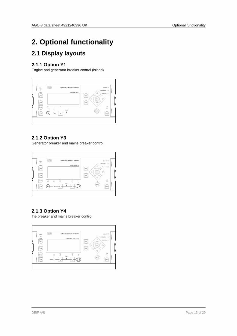
2.1.1 Option Y1Engine and generator breaker control (island)
Automatic Gen-set Controller
multi-line AGC
VIEW
LOG
Auto
Alarm Inh.
Self check ok
Power
SEL
BACK
MODE
JUMP
START
INFO
STOP
Alarm
Alarm
OnRun
G
Load
2.1.2 Option Y3Generator breaker and mains breaker control
Automatic Gen-set Controller
VIEW
LOG
Auto
Alarm Inh.
Self check ok
Power
SEL
BACK
MODE
JUMP
START
INFO
STOP
Alarm
Alarm
multi-line AGC
On On
Load
Run
G
2.1.3 Option Y4Tie breaker and mains breaker control
Automatic Gen-set Controller
VIEW
LOG
Auto
Alarm Inh.
Self check ok
Power
SEL
BACK
MODE
JUMP
START
INFO
STOP
Alarm
Alarm
multi-line AGC MAINS
On On
Load
AGC-3 data sheet 4921240396 UK Optional functionality
DEIF A/S Page 13 of 29
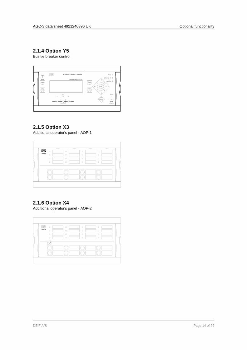
2.1.4 Option Y5Bus tie breaker control
Automatic Gen-set Controller
multi-line AGC BUS TIE
VIEW
LOG
Auto
Alarm Inh.
Self check ok
Power
SEL
BACK
On
INFO
JUMP
Alarm
Alarm
MODE
2.1.5 Option X3Additional operator's panel - AOP-1
AOP-1
2.1.6 Option X4Additional operator's panel - AOP-2
AOP-2
AGC-3 data sheet 4921240396 UK Optional functionality
DEIF A/S Page 14 of 29
2.2 Available options
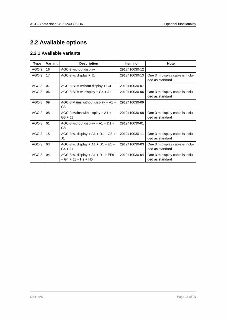
2.2.1 Available variants
Type Variant Description Item no. Note
AGC-3 16 AGC-3 without display 2912410030-12
AGC-3 17 AGC-3 w. display + J1 2912410030-13 One 3 m display cable is inclu-ded as standard
AGC-3 07 AGC-3 BTB without display + G4 2912410030-07
AGC-3 06 AGC-3 BTB w. display + G4 + J1 2912410030-06 One 3 m display cable is inclu-ded as standard
AGC-3 09 AGC-3 Mains without display + A1 +G5
2912410030-09
AGC-3 08 AGC-3 Mains with display + A1 +G5 + J1
2912410030-08 One 3 m display cable is inclu-ded as standard
AGC-3 01 AGC-3 without display + A1 + D1 +G8
2912410030-01
AGC-3 15 AGC-3 w. display + A1 + D1 + G8 +J1
2912410030-11 One 3 m display cable is inclu-ded as standard
AGC-3 03 AGC-3 w. display + A1 + D1 + E1 +G4 + J1
2912410030-03 One 3 m display cable is inclu-ded as standard
AGC-3 04 AGC-3 w. display + A1 + D1 + EF6+ G4 + J1 + H2 + H5
2912410030-04 One 3 m display cable is inclu-ded as standard
AGC-3 data sheet 4921240396 UK Optional functionality
DEIF A/S Page 15 of 29
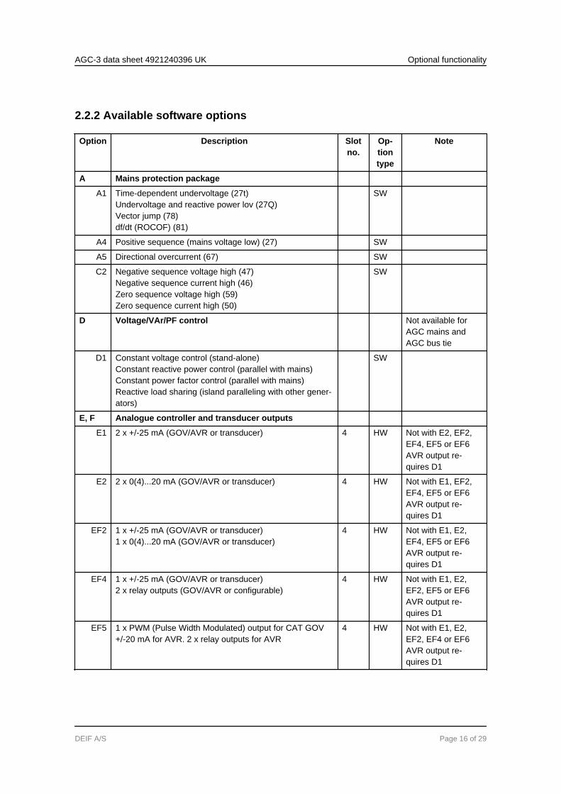
2.2.2 Available software options
Option Description Slotno.
Op-tiontype
Note
A Mains protection package
A1 Time-dependent undervoltage (27t)Undervoltage and reactive power lov (27Q)Vector jump (78)df/dt (ROCOF) (81)
SW
A4 Positive sequence (mains voltage low) (27) SW
A5 Directional overcurrent (67) SW
C2 Negative sequence voltage high (47)Negative sequence current high (46)Zero sequence voltage high (59)Zero sequence current high (50)
SW
D Voltage/VAr/PF control Not available forAGC mains andAGC bus tie
D1 Constant voltage control (stand-alone)Constant reactive power control (parallel with mains)Constant power factor control (parallel with mains)Reactive load sharing (island paralleling with other gener-ators)
SW
E, F Analogue controller and transducer outputs
E1 2 x +/-25 mA (GOV/AVR or transducer) 4 HW Not with E2, EF2,EF4, EF5 or EF6AVR output re-quires D1
E2 2 x 0(4)...20 mA (GOV/AVR or transducer) 4 HW Not with E1, EF2,EF4, EF5 or EF6AVR output re-quires D1
EF2 1 x +/-25 mA (GOV/AVR or transducer)1 x 0(4)...20 mA (GOV/AVR or transducer)
4 HW Not with E1, E2,EF4, EF5 or EF6AVR output re-quires D1
EF4 1 x +/-25 mA (GOV/AVR or transducer)2 x relay outputs (GOV/AVR or configurable)
4 HW Not with E1, E2,EF2, EF5 or EF6AVR output re-quires D1
EF5 1 x PWM (Pulse Width Modulated) output for CAT GOV+/-20 mA for AVR. 2 x relay outputs for AVR
4 HW Not with E1, E2,EF2, EF4 or EF6AVR output re-quires D1
AGC-3 data sheet 4921240396 UK Optional functionality
DEIF A/S Page 16 of 29
Option Description Slotno.
Op-tiontype
Note
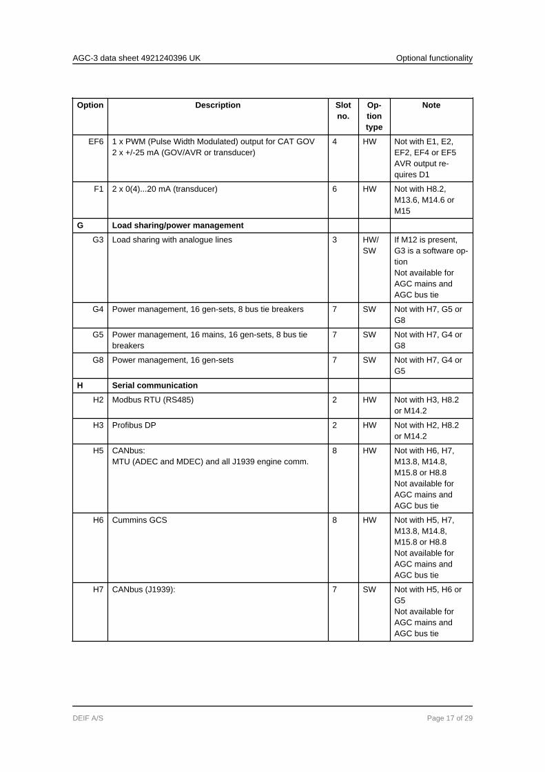
EF6 1 x PWM (Pulse Width Modulated) output for CAT GOV2 x +/-25 mA (GOV/AVR or transducer)
4 HW Not with E1, E2,EF2, EF4 or EF5AVR output re-quires D1
F1 2 x 0(4)...20 mA (transducer) 6 HW Not with H8.2,M13.6, M14.6 orM15
G Load sharing/power management
G3 Load sharing with analogue lines 3 HW/SW
If M12 is present,G3 is a software op-tionNot available forAGC mains andAGC bus tie
G4 Power management, 16 gen-sets, 8 bus tie breakers 7 SW Not with H7, G5 orG8
G5 Power management, 16 mains, 16 gen-sets, 8 bus tiebreakers
7 SW Not with H7, G4 orG8
G8 Power management, 16 gen-sets 7 SW Not with H7, G4 orG5
H Serial communication
H2 Modbus RTU (RS485) 2 HW Not with H3, H8.2or M14.2
H3 Profibus DP 2 HW Not with H2, H8.2or M14.2
H5 CANbus:MTU (ADEC and MDEC) and all J1939 engine comm.
8 HW Not with H6, H7,M13.8, M14.8,M15.8 or H8.8Not available forAGC mains andAGC bus tie
H6 Cummins GCS 8 HW Not with H5, H7,M13.8, M14.8,M15.8 or H8.8Not available forAGC mains andAGC bus tie
H7 CANbus (J1939): 7 SW Not with H5, H6 orG5Not available forAGC mains andAGC bus tie
AGC-3 data sheet 4921240396 UK Optional functionality
DEIF A/S Page 17 of 29
Option Description Slotno.
Op-tiontype
Note
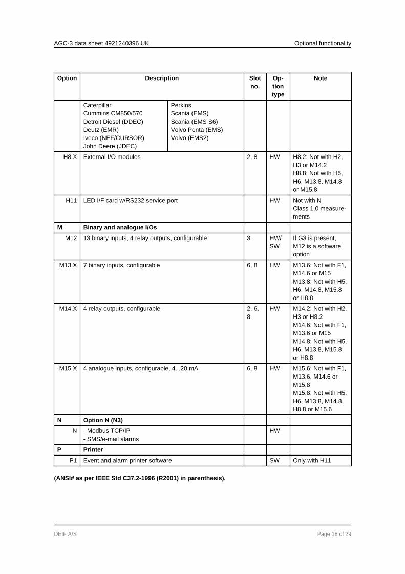
CaterpillarCummins CM850/570Detroit Diesel (DDEC)Deutz (EMR)Iveco (NEF/CURSOR)John Deere (JDEC)
PerkinsScania (EMS)Scania (EMS S6)Volvo Penta (EMS)Volvo (EMS2)
H8.X External I/O modules 2, 8 HW H8.2: Not with H2,H3 or M14.2H8.8: Not with H5,H6, M13.8, M14.8or M15.8
H11 LED I/F card w/RS232 service port HW Not with NClass 1.0 measure-ments
M Binary and analogue I/Os
M12 13 binary inputs, 4 relay outputs, configurable 3 HW/SW
If G3 is present,M12 is a softwareoption
M13.X 7 binary inputs, configurable 6, 8 HW M13.6: Not with F1,M14.6 or M15M13.8: Not with H5,H6, M14.8, M15.8or H8.8
M14.X 4 relay outputs, configurable 2, 6,8
HW M14.2: Not with H2,H3 or H8.2M14.6: Not with F1,M13.6 or M15M14.8: Not with H5,H6, M13.8, M15.8or H8.8
M15.X 4 analogue inputs, configurable, 4...20 mA 6, 8 HW M15.6: Not with F1,M13.6, M14.6 orM15.8M15.8: Not with H5,H6, M13.8, M14.8,H8.8 or M15.6
N Option N (N3)
N - Modbus TCP/IP- SMS/e-mail alarms
HW
P Printer
P1 Event and alarm printer software SW Only with H11
(ANSI# as per IEEE Std C37.2-1996 (R2001) in parenthesis).
AGC-3 data sheet 4921240396 UK Optional functionality
DEIF A/S Page 18 of 29

Options E1, E2, EF2, EF4, EF5 and EF6 are used for GOV/AVR control. Four relays are used asstandard in the AGC for GOV/AVR control. If selected, these options will replace the four re-lays.
Please notice that not all options can be selected for the same unit. Please refer to the chapter"Hardware overview" in this data sheet for further information about the location of the optionsin the unit.
AGC-3 data sheet 4921240396 UK Optional functionality
DEIF A/S Page 19 of 29
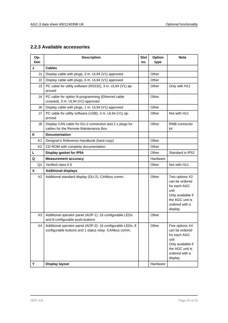
2.2.3 Available accessories
Op-tion
Description Slotno.
Optiontype
Note
J Cables
J1 Display cable with plugs, 3 m. UL94 (V1) approved Other
J2 Display cable with plugs, 6 m. UL94 (V1) approved Other
J3 PC cable for utility software (RS232), 3 m. UL94 (V1) ap-proved
Other Only with H11
J4 PC cable for option N-programming (Ethernet cablecrossed), 3 m. UL94 (V1) approved
Other
J6 Display cable with plugs, 1 m. UL94 (V1) approved Other
J7 PC cable for utility software (USB), 3 m. UL94 (V1) ap-proved
Other Not with H11
J8 Display CAN cable for DU-2 connection and 2 x plugs forcables for the Remote Maintenance Box
Other RMB connectorkit
K Documentation
K1 Designer's Reference Handbook (hard copy) Other
K2 CD-ROM with complete documentation Other
L Display gasket for IP54 Other Standard is IP52
Q Measurement accuracy Hardware
Q1 Verified class 0.5 Other Not with H11
X Additional displays
X2 Additional standard display (DU-2). CANbus comm. Other Two options X2can be orderedfor each AGCunitOnly available ifthe AGC unit isordered with adisplay
X3 Additional operator panel (AOP-1): 16 configurable LEDsand 8 configurable push-buttons
Other
X4 Additional operator panel (AOP-2): 16 configurable LEDs, 8configurable buttons and 1 status relay. CANbus comm.
Other Five options X4can be orderedfor each AGCunitOnly available ifthe AGC unit isordered with adisplay
Y Display layout Hardware
AGC-3 data sheet 4921240396 UK Optional functionality
DEIF A/S Page 20 of 29
Op-tion
Description Slotno.
Optiontype
Note
Y1 Engine and generator breaker control (island) Other Available forAGC gen-setcontroller
Y3 Generator breaker and mains breaker control Other Available forAGC gen-setcontroller
Y4 Tie breaker and mains breaker control Other Available forAGC mains con-troller
Y5 Bus tie breaker control Other Available forAGC BTB con-troller
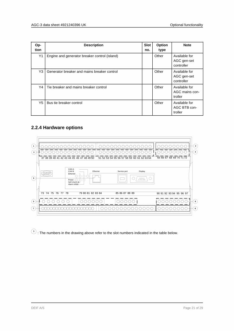
2.2.4 Hardware options
Ethernet
787776757473 96 979594929190 9389888785 8683 8482818079
727169 70686765 6662 6359 60 615856 575553 54 645251504947464443 45 4841403837 39 42
Service port Display
Ethernet
CAN BCAN A
Power
Self check okAlarm inhibit
1
4
9
5 6
3
7 8
2
1 : The numbers in the drawing above refer to the slot numbers indicated in the table below.
AGC-3 data sheet 4921240396 UK Optional functionality
DEIF A/S Page 21 of 29
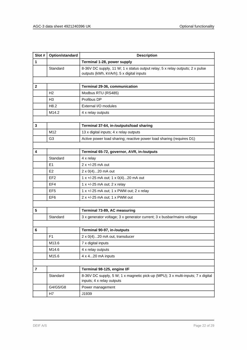
Slot # Option/standard Description
1 Terminal 1-28, power supply
Standard 8-36V DC supply, 11 W; 1 x status output relay; 5 x relay outputs; 2 x pulseoutputs (kWh, kVArh); 5 x digital inputs
2 Terminal 29-36, communication
H2 Modbus RTU (RS485)
H3 Profibus DP
H8.2 External I/O modules
M14.2 4 x relay outputs
3 Terminal 37-64, in-/outputs/load sharing
M12 13 x digital inputs; 4 x relay outputs
G3 Active power load sharing; reactive power load sharing (requires D1)
4 Terminal 65-72, governor, AVR, in-/outputs
Standard 4 x relay
E1 2 x +/-25 mA out
E2 2 x 0(4)...20 mA out
EF2 1 x +/-25 mA out; 1 x 0(4)...20 mA out
EF4 1 x +/-25 mA out; 2 x relay
EF5 1 x +/-25 mA out; 1 x PWM out; 2 x relay
EF6 2 x +/-25 mA out; 1 x PWM out
5 Terminal 73-89, AC measuring
Standard 3 x generator voltage; 3 x generator current; 3 x busbar/mains voltage
6 Terminal 90-97, in-/outputs
F1 2 x 0(4)...20 mA out, transducer
M13.6 7 x digital inputs
M14.6 4 x relay outputs
M15.6 4 x 4...20 mA inputs
7 Terminal 98-125, engine I/F
Standard 8-36V DC supply, 5 W; 1 x magnetic pick-up (MPU); 3 x multi-inputs; 7 x digitalinputs; 4 x relay outputs
G4/G5/G8 Power management
H7 J1939
AGC-3 data sheet 4921240396 UK Optional functionality
DEIF A/S Page 22 of 29
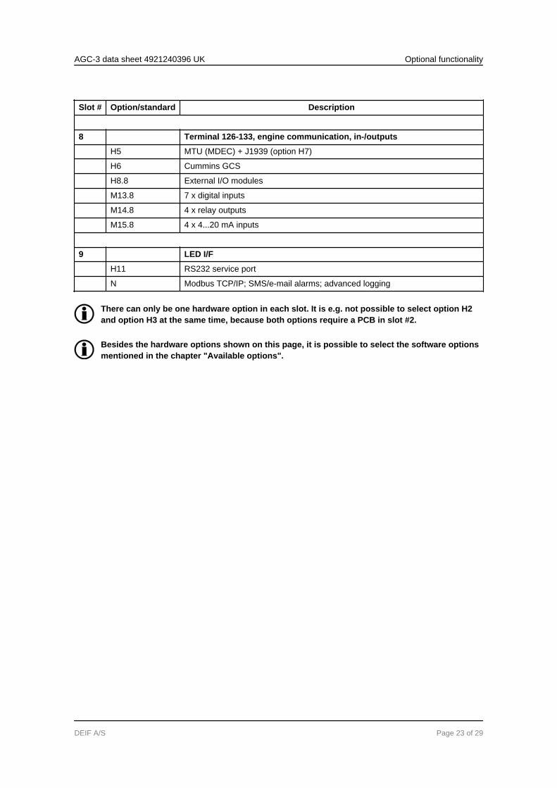
Slot # Option/standard Description
8 Terminal 126-133, engine communication, in-/outputs
H5 MTU (MDEC) + J1939 (option H7)
H6 Cummins GCS
H8.8 External I/O modules
M13.8 7 x digital inputs
M14.8 4 x relay outputs
M15.8 4 x 4...20 mA inputs
9 LED I/F
H11 RS232 service port
N Modbus TCP/IP; SMS/e-mail alarms; advanced logging
There can only be one hardware option in each slot. It is e.g. not possible to select option H2and option H3 at the same time, because both options require a PCB in slot #2.
Besides the hardware options shown on this page, it is possible to select the software optionsmentioned in the chapter "Available options".
AGC-3 data sheet 4921240396 UK Optional functionality
DEIF A/S Page 23 of 29
3. Technical information3.1 Specifications and dimensions
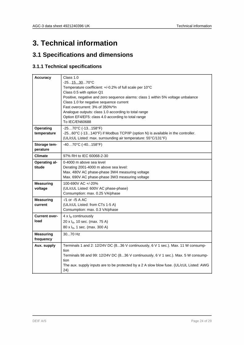
3.1.1 Technical specifications
Accuracy Class 1.0-25...15...30...70°CTemperature coefficient: +/-0.2% of full scale per 10°CClass 0.5 with option Q1Positive, negative and zero sequence alarms: class 1 within 5% voltage unbalanceClass 1.0 for negative sequence currentFast overcurrent: 3% of 350%*InAnalogue outputs: class 1.0 according to total rangeOption EF4/EF5: class 4.0 according to total rangeTo IEC/EN60688
Operatingtemperature
-25…70°C (-13...158°F)-25...60°C (-13...140°F) if Modbus TCP/IP (option N) is available in the controller.(UL/cUL Listed: max. surrounding air temperature: 55°C/131°F)
Storage tem-perature
-40…70°C (-40...158°F)
Climate 97% RH to IEC 60068-2-30
Operating al-titude
0-4000 m above sea levelDerating 2001-4000 m above sea level:Max. 480V AC phase-phase 3W4 measuring voltageMax. 690V AC phase-phase 3W3 measuring voltage
Measuringvoltage
100-690V AC +/-20%(UL/cUL Listed: 600V AC phase-phase)Consumption: max. 0.25 VA/phase
Measuringcurrent
-/1 or -/5 A AC(UL/cUL Listed: from CTs 1-5 A)Consumption: max. 0.3 VA/phase
Current over-load
4 x In continuously20 x In, 10 sec. (max. 75 A)80 x In, 1 sec. (max. 300 A)
Measuringfrequency
30...70 Hz
Aux. supply Terminals 1 and 2: 12/24V DC (8...36 V continuously, 6 V 1 sec.). Max. 11 W consump-tionTerminals 98 and 99: 12/24V DC (8...36 V continuously, 6 V 1 sec.). Max. 5 W consump-tionThe aux. supply inputs are to be protected by a 2 A slow blow fuse. (UL/cUL Listed: AWG24)
AGC-3 data sheet 4921240396 UK Technical information
DEIF A/S Page 24 of 29
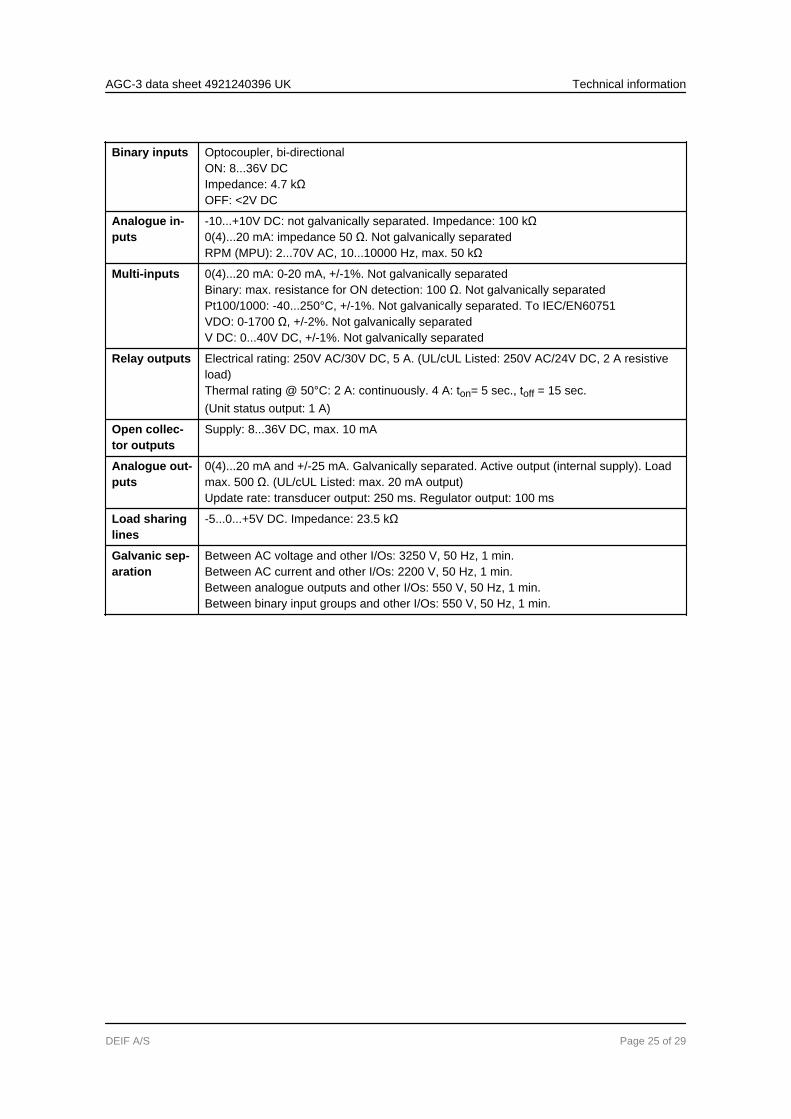
Binary inputs Optocoupler, bi-directionalON: 8...36V DCImpedance: 4.7 kΩOFF: <2V DC
Analogue in-puts
-10...+10V DC: not galvanically separated. Impedance: 100 kΩ0(4)...20 mA: impedance 50 Ω. Not galvanically separatedRPM (MPU): 2...70V AC, 10...10000 Hz, max. 50 kΩ
Multi-inputs 0(4)...20 mA: 0-20 mA, +/-1%. Not galvanically separatedBinary: max. resistance for ON detection: 100 Ω. Not galvanically separatedPt100/1000: -40...250°C, +/-1%. Not galvanically separated. To IEC/EN60751VDO: 0-1700 Ω, +/-2%. Not galvanically separatedV DC: 0...40V DC, +/-1%. Not galvanically separated
Relay outputs Electrical rating: 250V AC/30V DC, 5 A. (UL/cUL Listed: 250V AC/24V DC, 2 A resistiveload)Thermal rating @ 50°C: 2 A: continuously. 4 A: ton= 5 sec., toff = 15 sec.(Unit status output: 1 A)
Open collec-tor outputs
Supply: 8...36V DC, max. 10 mA
Analogue out-puts
0(4)...20 mA and +/-25 mA. Galvanically separated. Active output (internal supply). Loadmax. 500 Ω. (UL/cUL Listed: max. 20 mA output)Update rate: transducer output: 250 ms. Regulator output: 100 ms
Load sharinglines
-5...0...+5V DC. Impedance: 23.5 kΩ
Galvanic sep-aration
Between AC voltage and other I/Os: 3250 V, 50 Hz, 1 min.Between AC current and other I/Os: 2200 V, 50 Hz, 1 min.Between analogue outputs and other I/Os: 550 V, 50 Hz, 1 min.Between binary input groups and other I/Os: 550 V, 50 Hz, 1 min.
AGC-3 data sheet 4921240396 UK Technical information
DEIF A/S Page 25 of 29
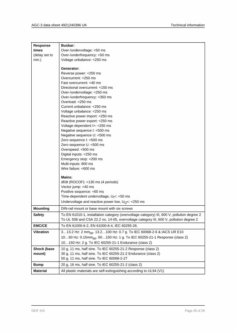
Responsetimes(delay set tomin.)
Busbar:Over-/undervoltage: <50 msOver-/underfrequency: <50 msVoltage unbalance: <250 ms
Generator:Reverse power: <250 msOvercurrent: <250 msFast overcurrent: <40 msDirectional overcurrent: <150 msOver-/undervoltage: <250 msOver-/underfrequency: <350 msOverload: <250 msCurrent unbalance: <250 msVoltage unbalance: <250 msReactive power import: <250 msReactive power export: <250 msVoltage-dependent I>: <250 msNegative sequence I: <500 msNegative sequence U: <500 msZero sequence I: <500 msZero sequence U: <500 msOverspeed: <500 msDigital inputs: <250 msEmergency stop: <200 msMulti-inputs: 800 msWire failure: <600 ms
Mains:df/dt (ROCOF): <130 ms (4 periods)Vector jump: <40 msPositive sequence: <60 msTime-dependent undervoltage, Ut<: <50 msUndervoltage and reactive power low, UQ<: <250 ms
Mounting DIN-rail mount or base mount with six screws
Safety To EN 61010-1, installation category (overvoltage category) III, 600 V, pollution degree 2To UL 508 and CSA 22.2 no. 14-05, overvoltage category III, 600 V, pollution degree 2
EMC/CE To EN 61000-6-2, EN 61000-6-4, IEC 60255-26.
Vibration 3…13.2 Hz: 2 mmpp. 13.2…100 Hz: 0.7 g. To IEC 60068-2-6 & IACS UR E1010…60 Hz: 0.15mmpp. 60…150 Hz: 1 g. To IEC 60255-21-1 Response (class 2)10…150 Hz: 2 g. To IEC 60255-21-1 Endurance (class 2)
Shock (basemount)
10 g, 11 ms, half sine. To IEC 60255-21-2 Response (class 2)30 g, 11 ms, half sine. To IEC 60255-21-2 Endurance (class 2)50 g, 11 ms, half sine. To IEC 60068-2-27
Bump 20 g, 16 ms, half sine. To IEC 60255-21-2 (class 2)
Material All plastic materials are self-extinguishing according to UL94 (V1)
AGC-3 data sheet 4921240396 UK Technical information
DEIF A/S Page 26 of 29
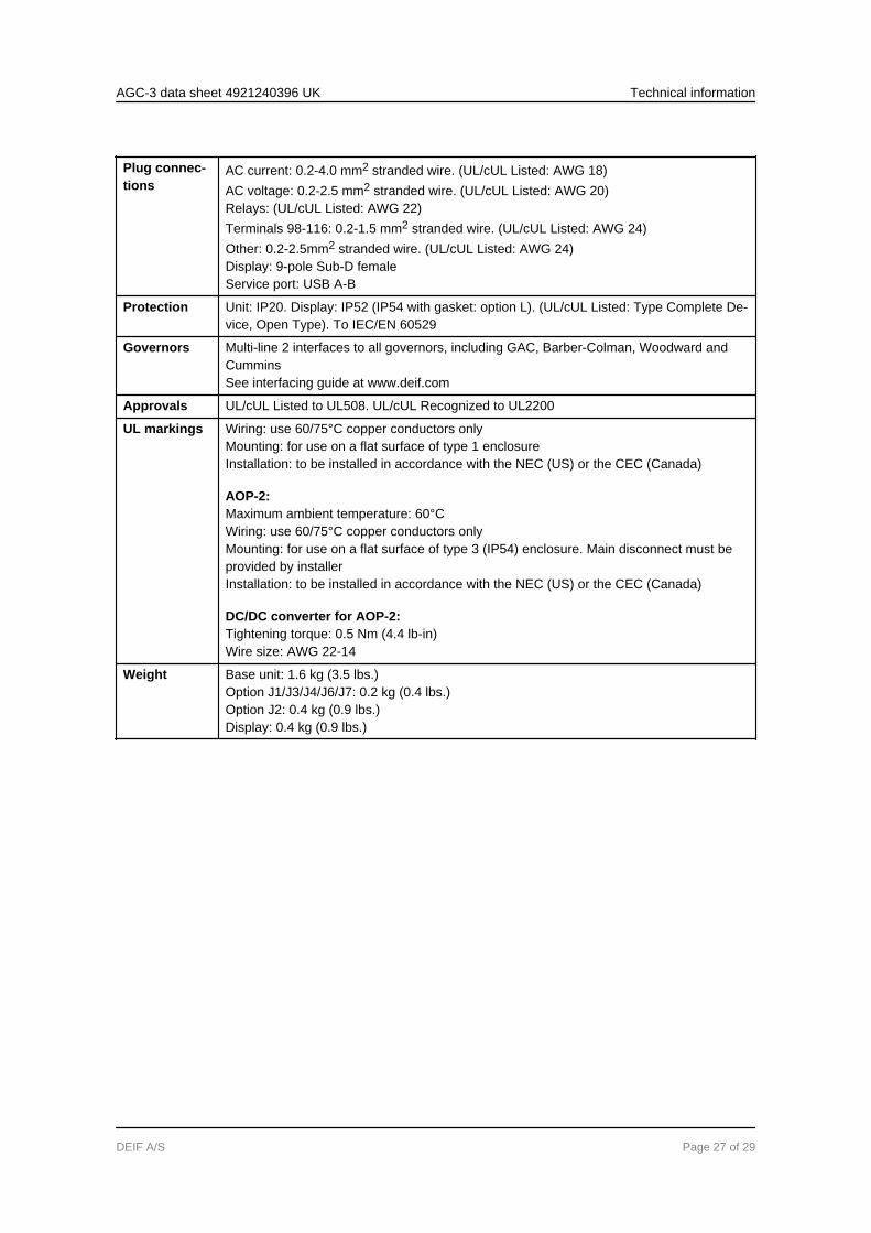
Plug connec-tions
AC current: 0.2-4.0 mm2 stranded wire. (UL/cUL Listed: AWG 18)AC voltage: 0.2-2.5 mm2 stranded wire. (UL/cUL Listed: AWG 20)Relays: (UL/cUL Listed: AWG 22)Terminals 98-116: 0.2-1.5 mm2 stranded wire. (UL/cUL Listed: AWG 24)Other: 0.2-2.5mm2 stranded wire. (UL/cUL Listed: AWG 24)Display: 9-pole Sub-D femaleService port: USB A-B
Protection Unit: IP20. Display: IP52 (IP54 with gasket: option L). (UL/cUL Listed: Type Complete De-vice, Open Type). To IEC/EN 60529
Governors Multi-line 2 interfaces to all governors, including GAC, Barber-Colman, Woodward andCumminsSee interfacing guide at www.deif.com
Approvals UL/cUL Listed to UL508. UL/cUL Recognized to UL2200
UL markings Wiring: use 60/75°C copper conductors onlyMounting: for use on a flat surface of type 1 enclosureInstallation: to be installed in accordance with the NEC (US) or the CEC (Canada)
AOP-2:Maximum ambient temperature: 60°CWiring: use 60/75°C copper conductors onlyMounting: for use on a flat surface of type 3 (IP54) enclosure. Main disconnect must beprovided by installerInstallation: to be installed in accordance with the NEC (US) or the CEC (Canada)
DC/DC converter for AOP-2:Tightening torque: 0.5 Nm (4.4 lb-in)Wire size: AWG 22-14
Weight Base unit: 1.6 kg (3.5 lbs.)Option J1/J3/J4/J6/J7: 0.2 kg (0.4 lbs.)Option J2: 0.4 kg (0.9 lbs.)Display: 0.4 kg (0.9 lbs.)
AGC-3 data sheet 4921240396 UK Technical information
DEIF A/S Page 27 of 29
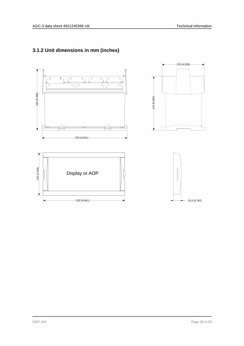
3.1.2 Unit dimensions in mm (inches)
Display or AOP
220 (8.661)
16
5 (
6.4
96
)
14
4 (
5.6
69
)
11
5 (
4.5
28
)
220 (8.661)
115 (4.528)
20.0 (0.787)
AGC-3 data sheet 4921240396 UK Technical information
DEIF A/S Page 28 of 29
4. Ordering information4.1 Order specifications and disclaimer
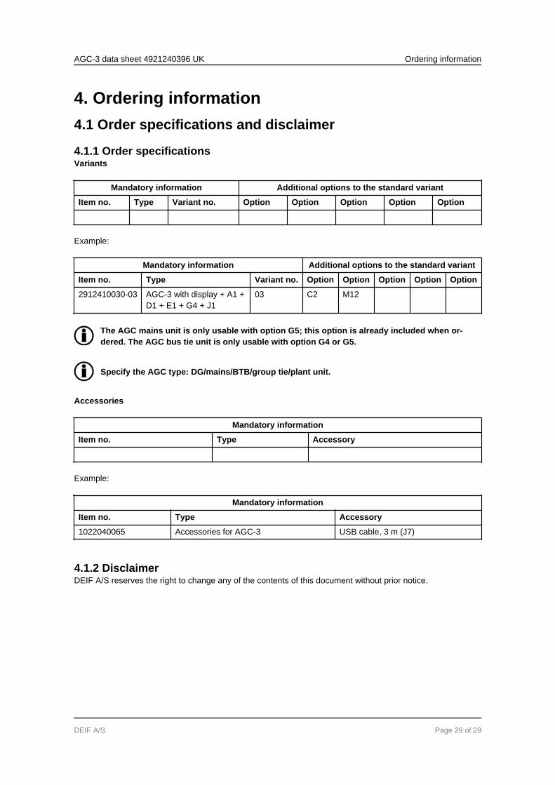
4.1.1 Order specificationsVariants
Mandatory information Additional options to the standard variant
Item no. Type Variant no. Option Option Option Option Option
Example:
Mandatory information Additional options to the standard variant
Item no. Type Variant no. Option Option Option Option Option
2912410030-03 AGC-3 with display + A1 +D1 + E1 + G4 + J1
03 C2 M12
The AGC mains unit is only usable with option G5; this option is already included when or-dered. The AGC bus tie unit is only usable with option G4 or G5.
Specify the AGC type: DG/mains/BTB/group tie/plant unit.
Accessories
Mandatory information
Item no. Type Accessory
Example:
Mandatory information
Item no. Type Accessory
1022040065 Accessories for AGC-3 USB cable, 3 m (J7)
4.1.2 DisclaimerDEIF A/S reserves the right to change any of the contents of this document without prior notice.
AGC-3 data sheet 4921240396 UK Ordering information
DEIF A/S Page 29 of 29