Embed Size (px)
Citation preview
Razvan Nane
Automatic Hardware Generationfor Reconfigurable Architectures

Automatic Hardware Generation forReconfigurable Architectures
PROEFSCHRIFT
ter verkrijging van de graad van doctoraan de Technische Universiteit Delft,
op gezag van de Rector Magnificus prof. ir. K.C.A.M Luyben,voorzitter van het College voor Promoties,
in het openbaar te verdedigen op
donderdag 17 april 2014 om 10:00 uur
door
Razvan NANE
Master of Science in Computer EngineeringDelft University of Technologygeboren te Boekarest, Roemenie
Dit proefschrift is goedgekeurd door de promotor:Prof. dr. K.L.M. Bertels
Samenstelling promotiecommissie:
Rector Magnificus voorzitterProf. dr. K.L.M. Bertels Technische Universiteit Delft, promotorProf. dr. E. Visser Technische Universiteit DelftProf. dr. W.A. Najjar University of California RiversideProf. dr.-ing. M. Hubner Ruhr-Universitat BochumDr. H.P. Hofstee IBM Austin Research LaboratoryDr. ir. A.C.J. Kienhuis Universiteit van LeidenDr. ir. J.S.S.M Wong Technische Universiteit DelftProf. dr. ir. Geert Leus Technische Universiteit Delft, reservelid
Automatic Hardware Generation for Reconfigurable ArchitecturesDissertation at Delft University of Technology
Copyright c© 2014 by R. Nane
All rights reserved. No part of this publication may be reproduced, stored in aretrieval system, or transmitted, in any form or by any means, electronic, mechanical,photocopying, recording, or otherwise, without permission of the author.
ISBN 978-94-6186-271-6
Printed by CPI Koninklijke Wohrmann, Zutphen, The Netherlands

To my family

Automatic Hardware Generation forReconfigurable Architectures
Razvan NaneAbstract
RECONFIGURABLE Architectures (RA) have been gaining popularityrapidly in the last decade for two reasons. First, processor clock fre-quencies reached threshold values past which power dissipation be-
comes a very difficult problem to solve. As a consequence, alternatives weresought to keep improving the system performance. Second, because Field-Programmable Gate Array (FPGA) technology substantially improved (e.g.,increase in transistors per mm2), system designers were able to use them for anincreasing number of (complex) applications. However, the adoption of recon-figurable devices brought with itself a number of related problems, of whichthe complexity of programming can be considered an important one. Oneapproach to program an FPGA is to implement an automatically generatedHardware Description Language (HDL) code from a High-Level Language(HLL) specification. This is called High-Level Synthesis (HLS). The avail-ability of powerful HLS tools is critical to managing the ever-increasing com-plexity of emerging RA systems to leverage their tremendous performance po-tential. However, current hardware compilers are not able to generate designsthat are comparable in terms of performance with manually written designs.Therefore, to reduce this performance gap, research on how to generate hard-ware modules efficiently is imperative. In this dissertation, we address the tooldesign, integration, and optimization of the DWARV 3.0 HLS compiler.
Dissimilar to previous HLS compilers, DWARV 3.0 is based on the CoSy com-piler framework. As a result, this allowed us to build a highly modular and ex-tendible compiler in which standard or custom optimizations can be easily inte-grated. The compiler is designed to accept a large subset of C-code as input andto generate synthesizable VHDL code for unrestricted application domains.To enable DWARV 3.0 third-party tool-chain integration, we propose severalIP-XACT (i.e., a XML-based standard used for tool-interoperability) exten-sions such that hardware-dependent software can be generated and integratedautomatically. Furthermore, we propose two new algorithms to optimize theperformance for different input area constraints, respectively, to leverage thebenefits of both jump and predication schemes from conventional processorsadapted for hardware execution. Finally, we performed an evaluation againststate-of-the-art HLS tools. Results show that application execution time wise,DWARV 3.0 performs, on average, the best among the academic compilers.
i

Acknowledgments
IT is a great pleasure to write this (last) part of my dissertation. The periodspent on working towards this goal has not always been easy, and, attimes, finalizing the thesis did not even seem possible. Fortunately, I am
lucky to have a very supporting family and warmhearted friends alongside, andto have met very helpful, understanding and skilful people that made the taskof completing the work both realizable and enjoyable. I am confronted nowwith words that cannot express my deepest gratitude I have for all these familymembers, friends and colleagues. For all the people who I forget at the time ofwriting, please accept my apology.
First of all, I want to thank my supervisor, prof. dr. Koen Bertels, for givingme the opportunity, research freedom and self-confidence to complete a Ph.D.study. I am also grateful for including me in different European projects thatallowed me to travel to project meetings, as well as to various internationalconferences. This allowed me not only to extend my professional network bymeeting, working and collaborating with well-known people in the field, butalso to discover different parts and cultures of the world. Thank you!
I want to thank my office colleagues who provided me with valuable infor-mation that aided me in the various tasks performed along the years. First,I want to specially thank Vlad-Mihai Sima for all discussions both work andnon-work related as well as for his immediate help with diverse Linux relatedtool issues. Furthermore, I am very thankful for the time taken to read thedraft version of the thesis and for providing insightful comments and improve-ment suggestions. Second, I want to thank Yana Yankova for helping me in thebeginning of the study and for creating the first version of the DWARV com-piler. Third, I thank Giacomo Machiori for providing me insights into varioushardware processes and for helping me solve some of the backend tool issues.
I thank all people involved in the European projects with whom I had the im-mense pleasure of working. I want to thank Bryan Olivier from ACE, whohelped me kick-start my CoSy experience, as well as to Hans van Someren alsofrom ACE for the optimization related discussions. Furthermore, I am grateful
iii
for the collaborations with Pedro Diniz, Joao Cardoso, Zlatko Petrov, MichaelHubner, Georgi Kuzmanov in the Framework Programme 7 REFLECT project,as well as with Bart Kienhuis, Sven van Haastregt and Todor Stefanov in theMEDEA+ SoftSoc project.
I consider myself very fortunate to have worked in an international departmentthat allowed me to meet people from all over the world. I want to thank Com-puter Engineering (CE) colleagues Cuong, Gustavo, Seyab, Roel, Changlin,Shanshan and many others for broadening my knowledge about other cultures.I thank also to CE colleagues Berna and Joost for helping me translate in Dutchthe propositions and the abstract. At the same time, I am grateful to fellow Ro-manian colleagues Bogdan, Catalin, George, Marius, Mihai, Nicoleta, Ancafor the interesting back home related discussions. I am thankful to the alwaysfriendly and helpful staff members Lidwina Tromp, Eef Hartman and Erik deVries who made administrative and technical support issues go unnoticeable.
A Latin expression says ‘mens sana incorpore sana’. I am very thankful thatthe CE department has a healthy attitude and encourages both sport and socialactivities. I am therefore very grateful to Said Hamdioui for organizing the CEweekly football games, and to the many enthusiast colleagues, Joost, Motta,Faisal, Imran, Lei, Adib and Innocent to name just a few who participate inthis activity. CE social events give lab members the chance to interact outsidework hours and have fun together. This made the work environment to feelmore than just a work place and for this I specially thank to Koen Bertels, whoalways encouraged such activities. I am also grateful to the organizers of thediverse social outings, Mafalda, Mahroo, Kamana and Mihai.
I need to thank also to my Monday football team members Bogdan, Wouter,Christian, Manuel, Sebastian, Ilian, Mehdi, Robert and Fernando, with whomI enjoyed many outdoor matches in the TU Delft ‘kunstgrass’ competition.For the pool competition fun, I thank my fellow pool team members over theyears Cristi, Pieter, Stein, Frank, Niels, Xavier, Michiel and Maurice. I wantto thank our very close friends Dana and Alin, Anca and Dan, Mafalda andVlad, Giacomo not only for great moments together, but also for their help andadvice regarding technical details on how to raise a child. Furthermore, I amgrateful to Mariana for her help during the intense months after the birth of mytwin daughters, period in which I finalized this thesis.
I am extremely grateful for the big family I have and for all the support theyhave given me over the years. I have no words to describe the appreciation Ihave for all my parents and grandparents for creating the environment in whichI was raised, for introducing me to mathematics since an early age or for en-
iv
couraging and supporting me to study abroad. I am grateful to my parents andparents-in-law for their help and support in organizing precious family eventsand for their invaluable help with the children. I thank my sister Ana for look-ing at life from a non-technical perspective and for fully committing to whatshe believes in. I thank my brother Robert for all the great moments spenttogether and for the many more to come. Flori and Ionut, you are the bestsiblings-in-law I could wish for and I am very happy to have you in my life. Ialso thank our (wedding) godparents Remus and Dana for their support, helpand for the many happy memories we have together. Nasu’, you are the firstwho suggested to me that doing a PhD is “not that bad”, and I am immenselygrateful for those talks in which I started to reconsider my future plans. Fur-thermore, I am very thankful to my extended family, Luci and Natalia, Andreiand Olesea, Mircea and Anca, Petre and Gina, who make each visit back homeone to remember and each family excursion to the mountains a dream.
Last, but most important, I cannot even begin to sketch how much I appreciateall the love and support I have received during the Ph.D. study from my wife.I am forever grateful that she made me understand that home means muchmore than the place where you were born, that she is extremely understandingespecially in not my best moments, for the many great memories we havetogether, but by far the most important, for being the best mother I could wishfor the three beautiful and healthy daughters we have together. Ti...ccm!
I want to express my gratitude towards all the above once again as the wordscannot express enough. I consider this dissertation the product of a truly won-derful journey that encompassed much more than the current text. It has been ajourney filled with professional, personal and cultural realizations, with plentyof ups and downs, period in which I did plenty of mistakes but from which Ilearned a lot. It is the the outcome of an extraordinary period in my life. Inow look happily towards the future and for the new challenges it will bring.However, until then, ‘Carpe diem!’
Razvan Nane Delft, The Netherlands, April 2014
v

Table of contents
Abstract . . . . . . . . . . . . . . . . . . . . . . . . . . . . . . . . . . i
Acknowledgments . . . . . . . . . . . . . . . . . . . . . . . . . . . . . iii
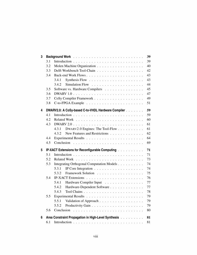
Table of Contents . . . . . . . . . . . . . . . . . . . . . . . . . . . . . vii
List of Tables . . . . . . . . . . . . . . . . . . . . . . . . . . . . . . . . xi
List of Figures . . . . . . . . . . . . . . . . . . . . . . . . . . . . . . . xiii
List of Listings . . . . . . . . . . . . . . . . . . . . . . . . . . . . . . . xvii
List of Acronyms and Symbols . . . . . . . . . . . . . . . . . . . . . . xix
1 Introduction . . . . . . . . . . . . . . . . . . . . . . . . . . . . . . 11.1 Problem Overview . . . . . . . . . . . . . . . . . . . . . . . 3
1.1.1 Dissertation Scope and Challenges . . . . . . . . . . . 61.1.2 Contribution of the thesis . . . . . . . . . . . . . . . . 7
1.2 Dissertation Organization . . . . . . . . . . . . . . . . . . . . 9
2 Related Work . . . . . . . . . . . . . . . . . . . . . . . . . . . . . . 132.1 High-Level Synthesis Tools . . . . . . . . . . . . . . . . . . . 14
2.1.1 Domain-Specific Languages . . . . . . . . . . . . . . 16
2.1.1.1 New Languages . . . . . . . . . . . . . . . 16
2.1.1.2 C-dialect Languages . . . . . . . . . . . . . 182.1.2 General-Purpose Languages . . . . . . . . . . . . . . 22
2.1.2.1 Procedural Languages . . . . . . . . . . . . 23
2.1.2.2 Object-Oriented Languages . . . . . . . . . 322.2 Summary of Tool Features . . . . . . . . . . . . . . . . . . . 342.3 Conclusion . . . . . . . . . . . . . . . . . . . . . . . . . . . 37
vii
3 Background Work . . . . . . . . . . . . . . . . . . . . . . . . . . . 393.1 Introduction . . . . . . . . . . . . . . . . . . . . . . . . . . . 393.2 Molen Machine Organization . . . . . . . . . . . . . . . . . . 403.3 Delft Workbench Tool-Chain . . . . . . . . . . . . . . . . . . 423.4 Back-end Work Flows . . . . . . . . . . . . . . . . . . . . . . 43
3.4.1 Synthesis Flow . . . . . . . . . . . . . . . . . . . . . 433.4.2 Simulation Flow . . . . . . . . . . . . . . . . . . . . 44
3.5 Software vs. Hardware Compilers . . . . . . . . . . . . . . . 453.6 DWARV 1.0 . . . . . . . . . . . . . . . . . . . . . . . . . . . 473.7 CoSy Compiler Framework . . . . . . . . . . . . . . . . . . . 493.8 C-to-FPGA Example . . . . . . . . . . . . . . . . . . . . . . 51
4 DWARV2.0: A CoSy-based C-to-VHDL Hardware Compiler . . . . . . . 594.1 Introduction . . . . . . . . . . . . . . . . . . . . . . . . . . . 594.2 Related Work . . . . . . . . . . . . . . . . . . . . . . . . . . 604.3 DWARV 2.0 . . . . . . . . . . . . . . . . . . . . . . . . . . . 61
4.3.1 DWARV2.0 Engines: The Tool-Flow . . . . . . . . . . 614.3.2 New Features and Restrictions . . . . . . . . . . . . . 62
4.4 Experimental Results . . . . . . . . . . . . . . . . . . . . . . 644.5 Conclusion . . . . . . . . . . . . . . . . . . . . . . . . . . . 69
5 IP-XACT Extensions for Reconfigurable Computing . . . . . . . . . . 715.1 Introduction . . . . . . . . . . . . . . . . . . . . . . . . . . . 715.2 Related Work . . . . . . . . . . . . . . . . . . . . . . . . . . 735.3 Integrating Orthogonal Computation Models . . . . . . . . . . 74
5.3.1 IP Core Integration . . . . . . . . . . . . . . . . . . . 745.3.2 Framework Solution . . . . . . . . . . . . . . . . . . 75
5.4 IP-XACT Extensions . . . . . . . . . . . . . . . . . . . . . . 765.4.1 Hardware Compiler Input . . . . . . . . . . . . . . . 775.4.2 Hardware-Dependent Software . . . . . . . . . . . . . 775.4.3 Tool Chains . . . . . . . . . . . . . . . . . . . . . . . 78
5.5 Experimental Results . . . . . . . . . . . . . . . . . . . . . . 795.5.1 Validation of Approach . . . . . . . . . . . . . . . . . 795.5.2 Productivity Gain . . . . . . . . . . . . . . . . . . . . 79
5.6 Conclusion . . . . . . . . . . . . . . . . . . . . . . . . . . . 80
6 Area Constraint Propagation in High-Level Synthesis . . . . . . . . . 816.1 Introduction . . . . . . . . . . . . . . . . . . . . . . . . . . . 81
viii
6.2 Background and Related Work . . . . . . . . . . . . . . . . . 836.3 Area Constrained Hardware Generation . . . . . . . . . . . . 84
6.3.1 Motivational Example and Problem Definition . . . . 846.3.2 Optimization Algorithm . . . . . . . . . . . . . . . . 876.3.3 Integration in DWARV2.0 . . . . . . . . . . . . . . . 88
6.4 Experimental Results . . . . . . . . . . . . . . . . . . . . . . 896.4.1 Experimental Environment . . . . . . . . . . . . . . . 906.4.2 Test Cases . . . . . . . . . . . . . . . . . . . . . . . . 906.4.3 Discussion . . . . . . . . . . . . . . . . . . . . . . . 92
6.5 Conclusion and Future Research . . . . . . . . . . . . . . . . 99
7 A Lightweight Speculative and Predicative Scheme for HW Execution 1017.1 Introduction . . . . . . . . . . . . . . . . . . . . . . . . . . . 1017.2 Related Work and Background . . . . . . . . . . . . . . . . . 1027.3 Speculative and Predicative Algorithm . . . . . . . . . . . . . 104
7.3.1 Motivational Examples . . . . . . . . . . . . . . . . . 1057.3.2 Algorithm Description and Implementation . . . . . . 108
7.4 Experimental Results . . . . . . . . . . . . . . . . . . . . . . 1117.5 Conclusion . . . . . . . . . . . . . . . . . . . . . . . . . . . 114
8 DWARV 3.0: Relevant Hardware Compiler Optimizations . . . . . . . 1158.1 Introduction . . . . . . . . . . . . . . . . . . . . . . . . . . . 1158.2 Hardware-Specific Optimizations . . . . . . . . . . . . . . . . 1168.3 CoSy Compiler Optimizations . . . . . . . . . . . . . . . . . 1248.4 Conclusions . . . . . . . . . . . . . . . . . . . . . . . . . . . 133
9 Hardware Compilers Evaluation . . . . . . . . . . . . . . . . . . . . 1359.1 Introduction . . . . . . . . . . . . . . . . . . . . . . . . . . . 1359.2 Tool Selection Criteria . . . . . . . . . . . . . . . . . . . . . 1369.3 Overview Selected Compilers for Evaluation . . . . . . . . . . 1379.4 Benchmark Overview . . . . . . . . . . . . . . . . . . . . . . 1409.5 Generated Hardware Overview . . . . . . . . . . . . . . . . . 1429.6 Experimental Results . . . . . . . . . . . . . . . . . . . . . . 1449.7 Conclusion . . . . . . . . . . . . . . . . . . . . . . . . . . . 148
10 Conclusions and Future Work . . . . . . . . . . . . . . . . . . . . . 14910.1 Summary . . . . . . . . . . . . . . . . . . . . . . . . . . . . 14910.2 Dissertation Contributions . . . . . . . . . . . . . . . . . . . 15110.3 Future Work . . . . . . . . . . . . . . . . . . . . . . . . . . . 153
ix
A Complete DWARV 3.0 Comparison Results . . . . . . . . . . . . . . 155
B Return on Investment Graphs . . . . . . . . . . . . . . . . . . . . . 161
Bibliography . . . . . . . . . . . . . . . . . . . . . . . . . . . . . . . . 163
List of Publications . . . . . . . . . . . . . . . . . . . . . . . . . . . . 173
Samenvatting . . . . . . . . . . . . . . . . . . . . . . . . . . . . . . . 177
Curriculum Vitae . . . . . . . . . . . . . . . . . . . . . . . . . . . . . . 179
x
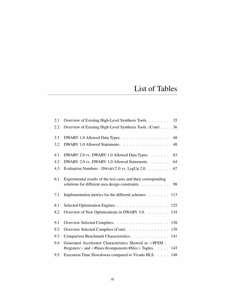
List of Tables
2.1 Overview of Existing High-Level Synthesis Tools. . . . . . . . 35
2.2 Overview of Existing High-Level Synthesis Tools. (Cont) . . . 36
3.1 DWARV 1.0 Allowed Data Types. . . . . . . . . . . . . . . . 48
3.2 DWARV 1.0 Allowed Statements. . . . . . . . . . . . . . . . 48
4.1 DWARV 2.0 vs. DWARV 1.0 Allowed Data Types. . . . . . . 63
4.2 DWARV 2.0 vs. DWARV 1.0 Allowed Statements. . . . . . . 64
4.3 Evaluation Numbers - DWARV2.0 vs. LegUp 2.0. . . . . . . . 67
6.1 Experimental results of the test cases and their correspondingsolutions for different area design constraints. . . . . . . . . . 98
7.1 Implementation metrics for the different schemes. . . . . . . . 113
8.1 Selected Optimisation Engines. . . . . . . . . . . . . . . . . . 125
8.2 Overview of New Optimizations in DWARV 3.0. . . . . . . . 134
9.1 Overview Selected Compilers. . . . . . . . . . . . . . . . . . 138
9.2 Overview Selected Compilers (Cont). . . . . . . . . . . . . . 139
9.3 Comparison Benchmark Characteristics. . . . . . . . . . . . . 141
9.4 Generated Accelerator Characteristics Showed as <#FSM :#registers> and <#lines:#components:#files> Tuples. . . . . 143
9.5 Execution Time Slowdowns compared to Vivado HLS. . . . . 148
xi
A.1 Complete Performance and Area Metrics for Vivado HLS andCommercialCompiler tools. . . . . . . . . . . . . . . . . . . . 156
A.2 Complete Performance and Area Metrics for DWARV 2.0 and3.0 tool versions. . . . . . . . . . . . . . . . . . . . . . . . . 158
A.3 Complete Performance and Area Metrics for LegUp 2.0 and3.0 tool versions. . . . . . . . . . . . . . . . . . . . . . . . . 159
A.4 Complete Performance and Area Metrics for PandA 0.9.0 and0.9.1 tool versions. . . . . . . . . . . . . . . . . . . . . . . . 160
xii
List of Figures
1.1 High-Level Overview of Tool-Chain Used to Program MOLEN. 5
1.2 Overview of the Connections Between Challenges, Chapters,Contributions and Publications. . . . . . . . . . . . . . . . . . 10
1.3 DWARV Version Evolution Based on Thesis Chapters. . . . . 12
2.1 Classification of High-Level Synthesis Tools based on InputLanguage. . . . . . . . . . . . . . . . . . . . . . . . . . . . . 15
3.1 An Overview of the Molen Platform with an Indication of theFlow of Instructions Through the Platform [60]. . . . . . . . . 40
3.2 Overview of the Delft Workbench Tool-Chain [60]. . . . . . . 42
3.3 Molen Backend Synthesis Flow. . . . . . . . . . . . . . . . . 44
3.4 Simulation Flow for Verifying Delft Workbench Auto-mated Reconfigurable VHDL Generator (DWARV) GeneratedVHDL Kernels. . . . . . . . . . . . . . . . . . . . . . . . . . 45
3.5 CoSy Framework Elements: Supervisor, Engines, Views andIntermediate Representation (IR). . . . . . . . . . . . . . . . 50
3.6 Xilinx Virtex-5 ML510 Hardware Platform. . . . . . . . . . . 51
3.7 Molen Implementation on the ML510 Hardware Platform. . . 52
3.8 C-to-FPGA steps: (a) CFG; (b) BB2 DFG; (c) BB2 generatedHardware. . . . . . . . . . . . . . . . . . . . . . . . . . . . . 55
4.1 DWARV 2.0 Engines. Clock-wise Sequential Execution ofEngines Starting from CFront. . . . . . . . . . . . . . . . . . 63
4.2 DWARV 2.0 Speedups vs. LegUp 2.0 times. . . . . . . . . . . 66
xiii
4.3 DWARV 2.0 vs. LegUp 2.0 Execution Time per Area Com-parison. . . . . . . . . . . . . . . . . . . . . . . . . . . . . . 69
5.1 H.264 Generation Tool-Chain Flow. . . . . . . . . . . . . . . 75
5.2 Connection between CCU and processor (left) and HdS layers(right). IMEM is the instruction memory of the processor,while DMEM is the data memory that is shared between boththe processor and the CCU. . . . . . . . . . . . . . . . . . . . 77
5.3 HdS IP-XACT extensions for layer 1. . . . . . . . . . . . . . 78
6.1 Motivational Examples: a) Formal Representation; b) No Un-roll and 1+, 1*, 1/ units; c) 2 Unroll and 1+, 1*, 1/ units; d) 2Unroll and 2+, 1*, 1/ units; e) 2 Unroll and 1+, 1*, 1/ units; f)2 Unroll and 1+, 1*, 2/ units; g) 4 Unroll and 1+, 1*, 1/ units;h) 4 Unroll and 4+, 4*, 4/ units; . . . . . . . . . . . . . . . . 85
6.2 optimizeForArea Main Function of the Algorithm. . . . . . . . 89
6.3 Algorithm Integration with DWARV2.0 Compiler. . . . . . . . 90
6.4 VectorSum test case. . . . . . . . . . . . . . . . . . . . . . . 91
6.5 MatrixMult test case. . . . . . . . . . . . . . . . . . . . . . . 91
6.6 FIR test case. . . . . . . . . . . . . . . . . . . . . . . . . . . 91
6.7 Matrix multiplication: 20% area design constraint. . . . . . . 93
6.8 Matrix multiplication ROI for 20% area design constraint. . . 95
6.9 Matrix multiplication: 30% area design constraint. . . . . . . 95
6.10 Matrix multiplication: 50% area design constraint. . . . . . . 96
6.11 Matrix multiplication: 100% area design constraint. . . . . . . 97
7.1 (a) C-Code; (b) Jump- ; (c) Predicated-Scheme. . . . . . . . . 103
7.2 Jump Scheme . . . . . . . . . . . . . . . . . . . . . . . . . . 104
7.3 Balanced if branches. . . . . . . . . . . . . . . . . . . . . . . 105
7.4 Unbalanced if branches . . . . . . . . . . . . . . . . . . . . . 105
7.5 Synthetic Case Studies. . . . . . . . . . . . . . . . . . . . . . 106
7.6 Execution Sequence of FSM States. . . . . . . . . . . . . . . 107
7.7 Engine Flow to Implement SaPA. . . . . . . . . . . . . . . . . 109
xiv
7.8 Data Dependency Graphs. . . . . . . . . . . . . . . . . . . . 110
7.9 Predicated Execution (PE) and SaPA speedups vs. JMP Scheme. 112
8.1 Various If Resolution Possibilities. . . . . . . . . . . . . . . . 117
8.2 Period-Aware Scheduling Flow. . . . . . . . . . . . . . . . . 119
8.3 Results for Placing Loop-Optimising Engines after Static Sin-gle Assignment (SSA) Engines. . . . . . . . . . . . . . . . . 126
8.4 Comparison of DWARV without (baseline) and with loop-unrolling (unroll factor set to 128). . . . . . . . . . . . . . . . 127
8.5 Influence of the maxfactor option on the execution time. . . . 130
8.6 Average execution time speedup of the different optimizationengines. . . . . . . . . . . . . . . . . . . . . . . . . . . . . . 131
8.7 Impact of optimisations for DWARV2.0 and LegUp 2.0. Thegraph shows pairwise normalized results of optimized vs base-line version for each compiler. The goal is to show the opti-mization potential. Results between compilers are thus notcomparable. . . . . . . . . . . . . . . . . . . . . . . . . . . . 132
9.1 Hardware Accelerator Required Memory Connections. . . . . 137
9.2 Execution Time Speedups of DWARV 3.0 compared toDWARV 2.0 . . . . . . . . . . . . . . . . . . . . . . . . . . . 144
9.3 Execution Times Normalized to DWARV3.0 Execution Time. . 145
9.4 Execution Cycles Normalized to DWARV3.0 Cycles. . . . . . 146
9.5 Estimated Max. Frequencies Normalized to DWARV3.0 Fre-quency. . . . . . . . . . . . . . . . . . . . . . . . . . . . . . 147
B.1 Matrix multiplication ROI for 30% area design constraint. . . 161
B.2 Matrix multiplication ROI for 50% area design constraint. . . 162
B.3 Matrix multiplication ROI for 100% area design constraint. . . 162
xv

List of Listings
3.1 C-to-FPGA Example Application and Instrumented AssemblyCode . . . . . . . . . . . . . . . . . . . . . . . . . . . . . . . 53
3.2 C-to-FPGA Example Function Code . . . . . . . . . . . . . . 54
3.3 C-to-FPGA Generated VHDL Excerpt for BB2 DFG . . . . . 56
8.1 Engine setlatency Excerpt . . . . . . . . . . . . . . . . . . . 119
8.2 Example of a Procedure Declaration with Multiple MemorySpaces. . . . . . . . . . . . . . . . . . . . . . . . . . . . . . 122
8.3 The loop of the count alive kernel . . . . . . . . . . . . . . . 128
8.4 The modified loop of the count alive kernel . . . . . . . . . . 128
8.5 The main loop of the bellmanford kernel . . . . . . . . . . . . 129
xvii

List of Acronyms and Symbols
ASIC Application-Specific Integrated Circuit
CCU Custom Computing Unit
CDFG Control Data Flow Graph
CSP Communication Sequential Processes
DDG Data Dependency Graph
CPU Central Processing Unit
CSE Common Subexpression Elimination
DSE Design Space Exploration
DSL Domain-Specific Language
DSP Digital Signal Processor
DWARV Delft Workbench Automated Reconfigurable VHDL Generator
DWB Delft Workbench
ELF Executable and Linkable Format
FF Flip Flop
FMax Maximum Frequency
FP Floating-Point
FPGA Field-Programmable Gate Array
FSM Finite State Machine
gcc GNU Compiler Collection
GPL General-Purpose Language
GPP General-Purpose Processor
xix
GPU Graphics Processing Unit
GUI Graphical User Interface
HDL Hardware Description Language
HdS Hardware-dependent Software
HLL High-Level Language
HLS High-Level Synthesis
HW/SW Hardware/Software
ILP Instruction Level Parallelism
IT Information Technology
IR Intermediate Representation
IP Intellectual Property
ISA Instruction Set Architecture
LLVM Low Level Virtual Machine
LUT Lookup Table
RA Reconfigurable Architecture
RC Reconfigurable Computing
RTL Register Transfer Level
SaPA Speculative and Predicative Algorithm
SoC System on Chip
SSA Static Single Assignment
VLIW Very Long Instruction Word
VHDL VHSIC Hardware Description Language
VHSIC Very-High-Speed Integrated Circuits
XREG eXchange Register
xx
1Introduction
COMPILERS are nowadays an indispensable software tool and are oneof the enablers behind the exponential growth of the InformationTechnology (IT) domain in the last decades. A compiler can be
defined as software that performs a translation of a code written in a high-level language (HLL) to a different, lower-level language, which is closerto the specific representation used by the target computer. The importanceof having compilers was immediately clear after the appearance of the firstcomputers on the market, i.e., the Atanasoff-Berry Computer (ABC) [87] andthe ENIAC [67] in the 1940s, for which the low-level manual programmingmethod (i.e., configuring the computers to perform useful work) was verytime consuming besides being error-prone. As a consequence of the difficultyof writing programs in the lowest-level programming language, the idea ofhigher abstractions appeared. Subsequently, an automated process (the com-piler) would translate from the abstract language to the low-level language.
Since Grace Hopper designed the first compiler for the A-0 System language in1952, a substantial number of compilers have been implemented and releasedby the software community for an increasing number of high-level program-ming languages. From these compilers, it is worth mentioning the FORTRANcompiler designed by John Backus for the IBM-704 computer in 1954-57,the ALGOL58 compiler for the first general imperative language in 1958, andthe first cross-compiler COBOL demonstrated on the UNIVAC II computerin 1960. This first generation of compilers influenced all subsequent com-pilers, such as Ada, C, Pascal, Simula. The increasing number of availablecompilers and high-level languages, coupled with the fast increasing proces-sor frequencies, the decreasing price for hardware resources, and the inventionof the internet are the main reasons for the wide-spread adoption of general-purpose computers in the late 1980s. The under-the-hood general Central Pro-cessing Unit (CPU)s of these computers is what made the IT domain one of
1
2 CHAPTER 1. INTRODUCTION
the biggest technological revolutions of the 20th century. Nevertheless, thisprogress would not have been possible without the availability of high-levelabstraction languages and associated compilers that hid the complexity of pro-gramming these general-purpose machines and that allowed for the fast cre-ation of general-purpose software by a wide range of engineers.
However, by the first decade of the 21st century, the frequency scaling problemof a CPU was becoming more evident as the size of the elemental unit of hard-ware, i.e., the transistor, was reaching its threshold value. At the same time,the demand for computational power was growing higher than ever before be-cause every industry was adopting IT. Until recently, the increasing processingrequirements were satisfied by increasing the frequency of the CPU. As thisbecomes increasingly difficult to achieve, new solutions to maintain the sameperformance increase per year ratio are investigated. One straightforward solu-tion is to increase the number of processing units, i.e., homogeneous multi-corecomputing. Unfortunately, this approach does not always scale. For example,for single applications containing large parts of parallelizable code, increasingthe number of cores beyond a small amount of cores (e.g., four cores) doesnot increase the application’s performance further. The main reason for thisperformance wall is the communication overhead, which increases greatly asthe number of cores increases and end up taking more time than the actualcomputations [23]. Furthermore, the fixed amount of computational resourceson CPUs is also a limiting factor in the possible speedup that can be achievedon these multi-core platforms. These problems, coupled with the drastic de-crease in price for the transistor, which led to the possibility of directly usinghardware as a general-purpose platform, made heterogeneous computing aneconomically feasible alternative.
A heterogeneous computing system can be defined as an electronic system thatis composed of different types of computational elements or cores, with eachcore being able to perform a different set of tasks than the others. What makesthis approach more flexible and has the potential to increase the system per-formance beyond the wall that homogeneous systems hit, is that some of thecores used in a heterogeneous system do not have predefined, generic, execu-tion pipeline stages that are needed to work for every scenario. Instead, thesecores can be programmed on the fly for the specific functionality required andcan allocate as many hardware resources as needed. This is particularly truefor Reconfigurable Architecture (RA)s applications used mostly in the embed-ded systems domain. However, the programmability of these new systems thatcan reconfigure based on system requirements poses major challenges, similarto how software compilers had their own challenges when they first appeared
1.1. PROBLEM OVERVIEW 3
more than 50 years ago; and as the history had taught us, the success and rateof adoption of these heterogeneous systems depends greatly on the maturityof tools (i.e., compilers) that do allows us to program them easily. Therefore,in this thesis we will address some of the issues regarding hardware compilersfor RA using applications from the embedded systems domain.
1.1 Problem Overview
Heterogeneous systems can be considered the next evolutionary step in thehistory of (high-performance) computers after homogeneous systems. Theiradvantage is the combination of general-purpose processors with predefinedspecific accelerators to perform the expensive (i.e., time-consuming) computa-tions for a particular (set of) application(s), thus increasing the overall systemperformance by delegating the computationally intensive tasks to those specificaccelerators (cores). However, designing predefined heterogeneous systems isnot always enough to guarantee their success. One of the most widely knownexamples of a heterogeneous system is the IBM’s Cell Broadband Engine pro-cessor [46]. Although the heterogeneous approach offers more flexibility andhigher performance than the standard homogeneous multi-core computing, thelack of reconfigurability of these architectures is still restrictive when it comesto performing well for various classes of computations. Consequently, theadoption of such a system can be prohibited by its high application develop-ment cost which cannot be amortized. Furthermore, implementing new algo-rithms on a predefined architecture can be also a very time consuming task. Inour opinion, even though the Cell processor was a success for the Playstation 3,because the Cell architecture did not include reconfigurable hardware to allowfor a different utilization of resources, it could not be easily applied in othertypes of applications. Although, at that time, due to the lack of mature toolsand languages to program reconfigurable devices, supporting reconfigurabilitywouldn’t have had a different impact on the outcome of the Cell processor,which was abandoned in 2009, the story of the Cell architecture showed theadvantages and the need to design reconfigurable devices.
Reconfigurable computing can be defined as a heterogeneous computer ar-chitecture with increased flexibility by allowing the specific hardware accel-erator resources available on the system to be reconfigured. The concept ofreconfigurable computing was introduced by computer scientist Gerald Estrinin the 1960s [25]. However, due to the lack of reconfigurable hardware avail-able that could be used for general-purpose applications, research for this type
4 CHAPTER 1. INTRODUCTION
of computing platforms stagnated until the second part of the 1990s. With theappearance of FPGA devices that could be reconfigured and were not expen-sive for general-purpose usage, the stage was set for a renaissance in this area.One of the first reconfigurable systems to be designed was the Garp proces-sor [17] from Berkeley University in 1997. The success of this research projectmarked the shift from homogeneous to heterogeneous reconfigurable systems,and in the first decade of the 21st century a number of academic reconfigurableprocessor architectures were proposed.
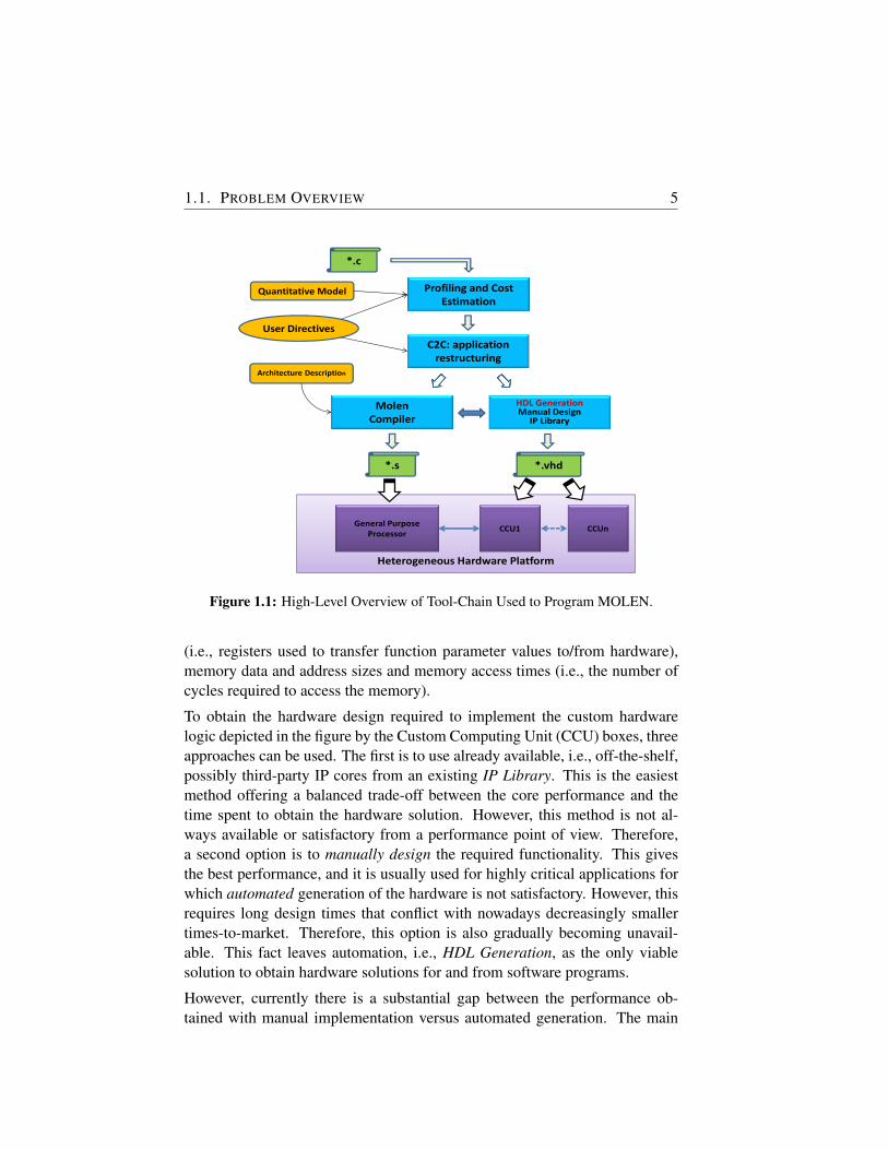
MOLEN Machine Organisation [24, 73] is a reconfigurable architecture de-veloped at TU Delft and one of those first heterogeneous reconfigurable sys-tems introduced in the 2000s. The MOLEN programming paradigm consistsof a one-time extension of the Instruction Set Architecture (ISA) to implementarbitrary functionality. In this thesis, we employ MOLEN as the reconfigurableplatform on which all experiments will be performed. This machine organiza-tion will be described in detail in Chapter 3. For the scope of this introduction,it is sufficient to understand that this architecture is essentially composed ofa CPU tightly connected to an FPGA, exchanging data via a shared memory.Figure 1.1 depicts the Delft Workbench tool-chain showing a simplified high-level overview of the steps involved in programming both the software andthe hardware parts of the MOLEN machine illustrated by the HeterogeneousHardware Platform box on the bottom of the figure.
One of the Molen objectives is to improve the performance of legacy code.Starting from an application completely written in a HLL, i.e., C in this par-ticular case denoted by *.c box, the first step is to profile the application andidentify the spots in the code that have high computational demands. In thiswork, unless stated otherwise, the application under discussion is written in C.The result of the Profiling and Cost Estimation execution will identify hotspotsthat are good candidates for acceleration when moving these parts to hardware.Based on a Quantitative Model that contains information about how to quan-tify the amount of computational resources required by a particular piece ofcode and how many resources it would allocate, coupled with particular UserDirectives that indicate how to interpret those quantifications in terms of whatcan be moved to hardware and what should not, the next step in the tool-chainrestructures the application. This is denoted by the C2C: application restruc-turing box in the figure, which transforms the code in such a way that furthertools down the tool-chain can process it. MOLEN Compiler is the tool thatcompiles the software part, outputting an assembly file *.s instrumented withcalls to hardware. These calls are set up according to a predefined ArchitectureDescription that contains information regarding sizes of exchange registers
1.1. PROBLEM OVERVIEW 5
Heterogeneous Hardware Platform
General Purpose
ProcessorCCU1 CCUn
*.c
Profiling and Cost
Estimation
C2C: application
restructuring
Quantitative Model
User Directives
Architecture Description
Molen
Compiler
HDL GenerationManual Design
IP Library
*.s *.vhd
Figure 1.1: High-Level Overview of Tool-Chain Used to Program MOLEN.
(i.e., registers used to transfer function parameter values to/from hardware),memory data and address sizes and memory access times (i.e., the number ofcycles required to access the memory).
To obtain the hardware design required to implement the custom hardwarelogic depicted in the figure by the Custom Computing Unit (CCU) boxes, threeapproaches can be used. The first is to use already available, i.e., off-the-shelf,possibly third-party IP cores from an existing IP Library. This is the easiestmethod offering a balanced trade-off between the core performance and thetime spent to obtain the hardware solution. However, this method is not al-ways available or satisfactory from a performance point of view. Therefore,a second option is to manually design the required functionality. This givesthe best performance, and it is usually used for highly critical applications forwhich automated generation of the hardware is not satisfactory. However, thisrequires long design times that conflict with nowadays decreasingly smallertimes-to-market. Therefore, this option is also gradually becoming unavail-able. This fact leaves automation, i.e., HDL Generation, as the only viablesolution to obtain hardware solutions for and from software programs.
However, currently there is a substantial gap between the performance ob-tained with manual implementation versus automated generation. The main
6 CHAPTER 1. INTRODUCTION
reason is that “programming” the hardware is not trivial. Several issues re-garding the programmability of the hardware are addressed in this work, suchas what optimizations are necessary, how to map software constructs to hard-ware logic elements, how to integrate hardware compilers in large tool-chainsand others. The main challenges addressed in this work are summarized inthe next section. Similar to the research performed in software compilers frommore than five decades ago, likewise research and optimizations are neces-sary to close the gap between automatically generated hardware and manualdesigns as it is still the case today. Therefore, in this thesis we focus on thedevelopment, optimization, and integration of a hardware compiler.
1.1.1 Dissertation Scope and Challenges
The work performed in the scope of this dissertation was conducted within theseventh Framework Programme (FP7) REFLECT [70] and the Medea+ Soft-Soc European Union (EU) projects. The first project focused on a holisticapproach to integrate the concept of software “aspects” into the software/hard-ware co-design flow by developing, implementing, and evaluating a novelcompilation and synthesis system approach for FPGA-based platforms. TheREFLECTs approach intended to solve some of the problems that appear whenefficiently mapping computations to FPGA-based systems. In particular, theuse of aspects and strategies was proposed to allow developers to try differ-ent design patterns and to achieve solutions design-guided by non-functionalrequirements. In this respect, the need of a modular and easily extendable hard-ware compiler was essential to allow the run-time adaptation of the hardwaregeneration process based on different aspect requirements that implied thatdifferent selections and orderings of compiler optimizations are possible. Thesecond project, SoftSoC, aimed at solving the main System on Chip (SoC) pro-ductivity bottleneck by providing Hardware-dependent Software (HdS)1 solu-tions to enable SoC designers to aggregate multiple HW IPs with their associ-ated HdS into an efficient design. Concretely, a method was sought to allow aseamless integration of different party tools based on HdS and IP-XACT [1]descriptions. IP-XACT is a XML-based standard to describe hardware, i.e.,Intellectual Property (IP) cores, to facilitate a seamless integration in third-party SoC. One particular case study investigated how to integrate two orthog-onal computational models, namely DWARV2.0 respectively Compaan Design(described in Chapter 5), using the above mentioned descriptions. The com-putational models differ in the way they treat the memory, i.e., the former tool
1HdS is an IP (software) driver. These two definitions are used interchangeably in the text.
1.1. PROBLEM OVERVIEW 7
assumes a shared memory interface, whereas the latter assumes a distributedmemory model.
Therefore, the challenges addressed in this thesis can be directly derived froma subset of goals of the above-mentioned projects and can be summarized asfollows:
1. Analyze, design, and implement a highly modular hardware compilerthat can be seamlessly extended with new or existing optimizations. Fur-thermore, the compiler should allow integration of external modules tofacilitate an aspect-oriented design methodology.
2. Analyze, test, and propose a first set of IP-XACT extensions to supportmodeling of HdS in order to facilitate the automatic integration of gen-erated hardware descriptions into large multi-vendor IPs SoC projects.Furthermore, the implications regarding the support available in a hard-ware compiler should be studied.
3. Analyze how area constraints are propagated through a hardware com-piler. Concretely, investigate and devise an optimization model that sup-ports the propagation of area constraints to the final generated HDL codeoutput.
4. Analyze what well-known software optimizations can be applied tohardware generation. Look at classes of software optimizations andstudy if, how, and when these are beneficial in a hardware context. Atthe same time, consider individual optimizations and investigate howthey should be changed given the new hardware context in which moreresources became available.
5. Provide an overview and extensive comparison of different hardwarecompilers, both commercial and academic.
1.1.2 Contribution of the thesis
The main contributions of the work proposed in this dissertation are directlyrelated to the described challenges. The following list briefly describes thecontributions, where each numbered contribution corresponds exactly to thechallenges with the same number from the previous list:
1. Design, implement, and evaluate a new research compiler based on theCoSy commercial compiler framework. This new version of DWARV
8 CHAPTER 1. INTRODUCTION
has a higher coverage of accepted C-language constructs. This is par-tially because the underlying compiler framework offers standard low-ering (i.e., from high-level to low-level constructs mapping) transforma-tions, which essentially allow the developer to implement just the impor-tant hardware primitives (e.g., goto state) from which all high-level con-structs are composed. Furthermore, using CoSy, we obtain a highly ro-bust and modular compiler that can be integrated in different tool-chainsby extending it with custom compiler transformations to process thirdparty information (e.g., coming from aspect oriented descriptions) andconfigure the process of hardware generation accordingly. We validateand demonstrate the performance of the DWARV2.0 compiler againstanother state-of-the-art research compiler. We show kernel-wise perfor-mance improvements up to 4.41x compared to LegUp 2.0 compiler [18].
2. Propose HdS based IP-XACT extensions and show how hardware ker-nels can be integrated into third party tool(-chains) automatically by us-ing such descriptions. Therefore, we elaborate on the expressiveness ofIP-XACT for describing HdS meta-data. Furthermore, we address theautomation of HdS generation in the Reconfigurable Computing (RC)field, where IPs and their associated HdS are generated on the fly, and,therefore, are not fully predefined. We combine in this respect twoproven technologies used in MPSoC design, namely IP-XACT andHdS, to integrate automatically different architectural templates used inRC systems. We investigate and propose a first set of three IP-XACTextensions to allow this automatic generation and integration of HdS inRC tool-chains.
3. Propose for streaming applications, i.e., loop-based, an optimization tocontrol the unroll factor and the number of components, e.g., Floating-Point (FP) cores, when the area available for the kernel is limited. Weassume thus that the hardware area for which a to be generated hardwareaccelerator is limited. In this respect, two important parameters have tobe explored, namely the degree of parallelism (i.e., the loop unrollingfactor) and the number of functional modules (e.g., FP operations) usedto implement the source HLL code. Determining without any humanintervention these parameters is a key factor in building efficient HLL-to-HDL compilers and implicitly any Design Space Exploration (DSE)tool. To solve this problem, we propose an optimization algorithm tocompute the above parameters automatically. This optimization is addedas an extension to the DWARV2.0 hardware compiler.
1.2. DISSERTATION ORGANIZATION 9
4. Propose for control based applications, i.e., executing path selectionstatements, a predication scheme suitable and generally applicablefor hardware compilers called Speculative and Predicative Algorithm(SaPA). This technique takes into account the characteristics of a C-to-VHDL compiler and the features available on the target platform. In-struction predication is a well-known compiler optimization technique,however, current C-to-VHDL compilers do not take full advantage ofthe possibilities offered by this optimization. More specifically, we pro-pose a method to increase performance in the case of unbalanced if-then-else branches. These types of branches are problematic because,when the jump instructions are removed for the predicated execution, ifthe shorter branch is taken, slowdowns occur because (useless) instruc-tions from the longer branch still need to be executed. Based on bothsynthetic and real world applications we show that our algorithm doesnot substantially increase the resource usage while the execution time isreduced in all cases for which it is applied.
5. Provide an extensive evaluation of state-of-the-art hardware compilersagainst DWARV3.0. At the same time, a thorough retrospection of ex-isting high-level tools has been performed. The comparison included anumber of hardware compilers that comply with some predefined crite-ria in which DWARV can be included, as well. In particular, we lookedat VivadoHLS, another ComercialCompiler, LegUp2.0 and 3.0, PandA0.9.0 and 0.9.1, and two versions of DWARV, i.e. 2.0 and 3.0. Theresults obtained will show how all these compilers compare to VivadoHLS, which on average generated the most efficient hardware.
1.2 Dissertation Organization
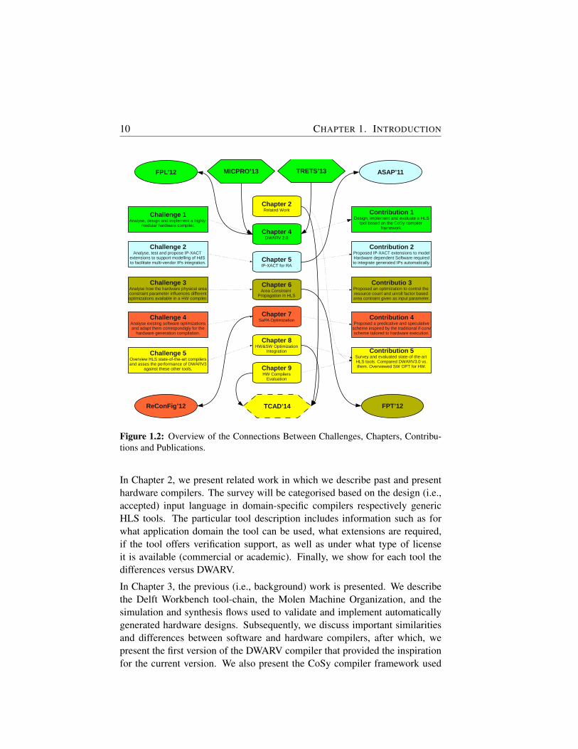
The work described in this dissertation is organized in 10 chapters. Figure 1.2highlights the chapters by relating them visually to the addressed challengesand the specific contributions made, while showing the chapter connectionsto the published papers and journals in the scope of this dissertation. Theoval box represents a conference proceeding while the hexagon represents ajournal publication. Furthermore, incoming chapter edges depict the fact thatthe source chapter was published in the target publication while the reverserepresent the fact that the source publication was based on the target chapter.The dotted hexagon on the bottom of the figure represents the fact that thepublication is submitted. The topic of each chapter is described below.
10 CHAPTER 1. INTRODUCTION
Chapter 2Related Work
Chapter 4DWARV 2.0
Chapter 5IP-XACT for RA
Chapter 6Area Constraint
Propagation in HLS
Chapter 8HW&SW Optimization
Integration
Chapter 7SaPA Optimization
Chapter 9HW Compilers
Evaluation
Challenge 1Analyse, design and implement a highly
modular hardware compiler.
FPL’12 ASAP’11
ReConFig’12 FPT’12TCAD’14
TRETS’13MICPRO’13
Challenge 2Analyse, test and propose IP-XACT
extensions to support modelling of HdS to facilitate multi-vendor IPs integration.
Challenge 3Analyse how the hardware physical areaconstraint parameter influences differentoptimizations available in a HW compiler.
Challenge 4Analyse existing software optimizationsand adapt them correspondigly for the
hardware generation compilation.
Challenge 5Overview HLS state-of-the-art compilersand asses the performance of DWARV3
against these other tools.
Contribution 1Design, implement and evaluate a HLS
tool based on the CoSy compiler framework.
Contribution 2Proposed IP-XACT extensions to modelHardware dependent Software requiredto integrate generated IPs automatically.
Contributio 3Proposed an optimization to control the resource count and unroll factor based area contraint given as input parameter.
Contribution 4Proposed a predicative and speculative
scheme inspired by the traditional if-convscheme tailored to hardware execution.
Contribution 5Survey and evaluated state-of-the-art HLS tools. Compared DWARV3.0 vs.them. Overviewed SW OPT for HW.
Figure 1.2: Overview of the Connections Between Challenges, Chapters, Contribu-tions and Publications.
In Chapter 2, we present related work in which we describe past and presenthardware compilers. The survey will be categorised based on the design (i.e.,accepted) input language in domain-specific compilers respectively genericHLS tools. The particular tool description includes information such as forwhat application domain the tool can be used, what extensions are required,if the tool offers verification support, as well as under what type of licenseit is available (commercial or academic). Finally, we show for each tool thedifferences versus DWARV.
In Chapter 3, the previous (i.e., background) work is presented. We describethe Delft Workbench tool-chain, the Molen Machine Organization, and thesimulation and synthesis flows used to validate and implement automaticallygenerated hardware designs. Subsequently, we discuss important similaritiesand differences between software and hardware compilers, after which, wepresent the first version of the DWARV compiler that provided the inspirationfor the current version. We also present the CoSy compiler framework used
1.2. DISSERTATION ORGANIZATION 11
to implement the new version of DWARV. Finally, we describe the completeC-to-FPGA tool-flow based on a simple example.
In Chapter 4, we describe DWARV2.0, the first DWARV version implementedin CoSy. The performance of the new version will be benchmarked by com-paring and evaluating it against the LegUp 2.0 academic compiler.
Chapter 5 presents the HdS IP-XACT based extensions required when gen-erating code for RC applications. These extensions are needed because thecurrent IP-XACT standard supports only hardware modeling (i.e., IP related),but it does not allow to model software, that is, to model IP drivers that are re-quired to integrate generated hardware automatically in SoC. The IP-XACTstandard is used to facilitate the automatic integration of existing hardwarecomponents used by hardware designers in SoC design.
In Chapter 6, an optimization algorithm to generate hardware kernels subject toinput area constraints is presented. These area constraints are highly importantin the Molen context, where we can have a maximum number of acceleratorsthat can be executed in parallel by a specific architecture implementation. Inthis respect, generating hardware accelerators that can fit these a prior definedFPGA slots is very important.
In Chapter 7, we present another hardware specific optimization. This op-timization, called SaPA, is based on a relaxation of the traditional softwareif-conversion technique. The results obtained indicate that this optimizationcould be universally applied in each hardware compiler, because it does not de-crease the accelerator performance (not even in unbalanced if-then-else cases),while, at the same time, the hardware area is negligibly increased.
In Chapter 8, we present important hardware optimizations that allowed us tooptimize DWARV2.0 by a factor of 2x to 3x. Furthermore, we present currentwork oriented towards the automation of selecting and integrating optimiza-tions in a compiler on a case by case basis. The reason behind this work is thefact that including existing standard optimizations randomly in a compiler isnot a recipe for success. The order in which these are applied and how they areconfigured play a very important role, as well.
Finally, Chapter 9 will show comparison results for DWARV3.0 against anewer version of LegUp (i.e. LegUp 3.0) and other three compilers, i.e. VivadoHLS, PandA 0.9.1 and another CommercialCompiler (CC2). Conclusions arepresented in Chapter 10, where we summarize the main contributions of thisthesis, and we propose a list of open questions and future research directions.
2CC is not a real name. This is hidden to avoid license issues w.r.t publication rights
12 CHAPTER 1. INTRODUCTION
DWARV 1.0 DWARV 2.0 DWARV 3.0
Chapter 4Chapter 6Chapter 7Chapter 8
used in Chapter 1,2,3 used in Chapter 5 used in Chapter 9
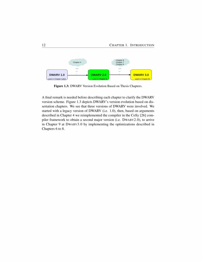
Figure 1.3: DWARV Version Evolution Based on Thesis Chapters.
A final remark is needed before describing each chapter to clarify the DWARVversion scheme. Figure 1.3 depicts DWARV’s version evolution based on dis-sertation chapters. We see that three versions of DWARV were involved. Westarted with a legacy version of DWARV (i.e. 1.0), then, based on argumentsdescribed in Chapter 4 we reimplemented the compiler in the CoSy [26] com-piler framework to obtain a second major version (i.e. DWARV2.0), to arrivein Chapter 9 at DWARV3.0 by implementing the optimizations described inChapters 6 to 8.

2Related Work
HARDWARE compilers that take as input a High-Level Language (HLL),e.g., C, and generate Hardware Description Language (HDL), e.g.,VHDL, are maybe not a new but increasingly important research
topic. These compilers have been used increasingly in the last decade to gener-ate hardware for various application domains in order to accelerate the compu-tationally intensive part(s), when adopting the Hardware/Software (HW/SW)co-design paradigm. One example is to speedup a MJPEG application by gen-erating VHDL code for the DCT function (called also a kernel), synthesiz-ing it, and merging the generated bit file with the Executable and LinkableFormat (ELF) file generated by the software compiler for the rest of the ap-plication and running it on a mixed platform, i.e., processor (e.g., ARM, Pow-erPC) combined with a co-processor (e.g., FPGA) [73].
To do fast design space exploration of the different configuration options avail-able and select the best mapping (i.e., HW/SW partitioning depending onthe available area and required throughput), we need to be able to evaluatethe hardware implementations for the different functions chosen for hardwareexecution. Performing this task by hand requires not only hardware designknowledge to implement these application functions in hardware, but also re-quires the developer to go through the typical iterative implement-test-debug-implement cycle, which is very time consuming. This, in turn, will drasticallylimit the effectiveness of the design space exploration analysis. As a result, theever-increasing time-to-market pressure will not be reduced. A solution to thisproblem are hardware generators, referred to also as high-level synthesis tools,which are essentially HLL-to-HDL compilers. This allows the designer toimmediately obtain a hardware implementation and skip the time-consumingiterative development cycle altogether.
13
14 CHAPTER 2. RELATED WORK
2.1 High-Level Synthesis Tools
In this section, we present related research projects that addressed the processof automating HDL generation from HLLs. We will describe here importantfeatures such as supported input/output languages, underlying compiler frame-work upon which the tool has been built (where this information is available),and as a direct consequence, the optimizations available, the target applica-tion domains, support for floating- and/or fixed-point arithmetic, and if thetool supports automatic verification by means of automatic test bench genera-tion. Therefore, in this chapter we will emphasize on the HLS state-of-the-artand describe how the DWARV compiler compares to this other work in thefield. The goal is to show that our compiler, when compared with the oth-ers, accepts a large sub-set of unmodified C-language constructs, and that itgenerates code for any application domain code, which is one of the designgoals behind DWARV. In subsequent chapters, we will show that DWARV ismodular, and it can be easily extended by including two custom designed op-timizations (Chapters 6 and 7), as well as that it has great potential for furtherimprovement by adding standard CoSy framework optimizations (Chapter 8).Finally, Chapter 9 will show that DWARV3.0’s performance, the final versionat the time of writing this dissertation, is comparable with commercial com-pilers, and, that between the compared academic compilers, for the presentedapplications and requirements, it performs the best.
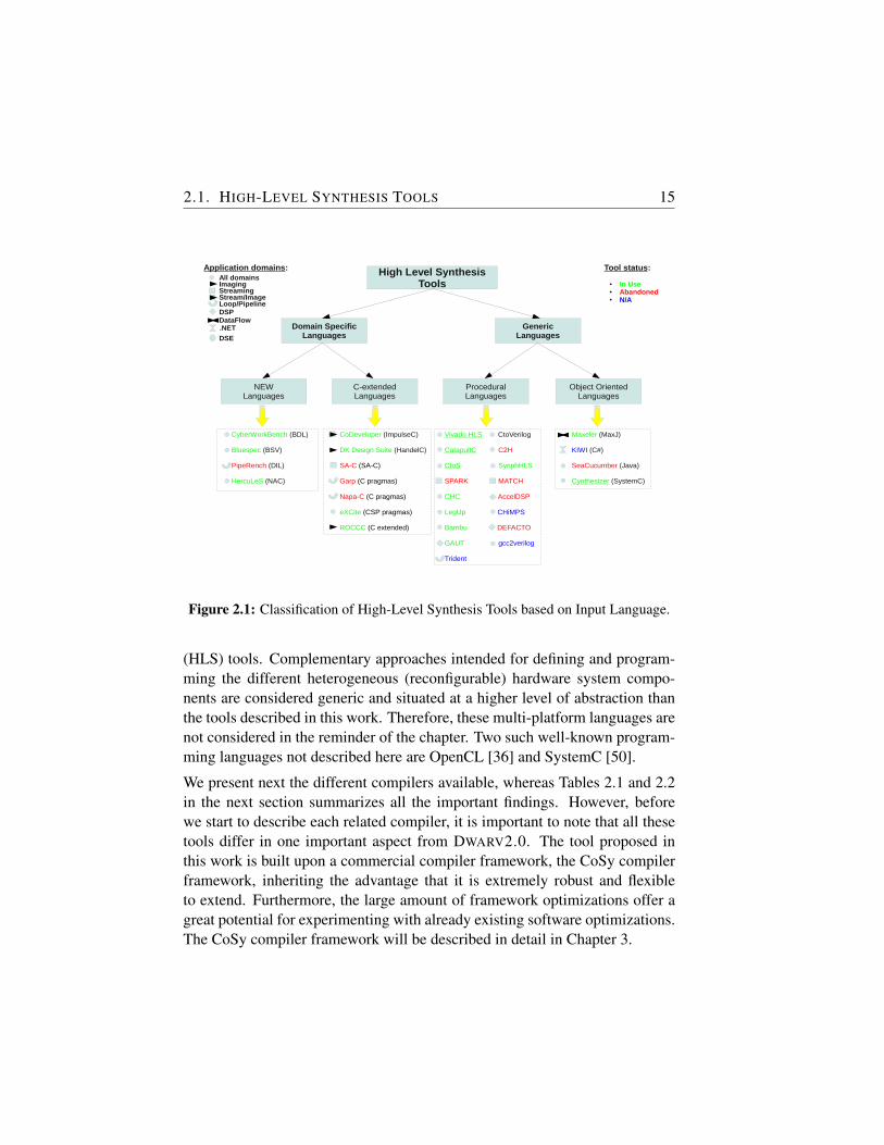
The tool presentation will be done according to a classification dependingonly on the design input language as shown in Figure 2.1. We distinguishbetween two major categories, namely tools that accept Domain-SpecificLanguage (DSL)s and tools that are based on General-Purpose Language(GPL)s. DSLs are composed of new languages invented specially for a par-ticular tool-flow and C-based dialects, which are languages based on C ex-tended with pragmas/annotations to convey specific hardware information tothe tool. GPLs are also split in two categories, namely procedural languagesand object-oriented languages. Under each category, the corresponding toolsare listed in green, red or blue fonts standing for in use, abandoned, respec-tively, no information is known about the status of the tool. Furthermore, thebullet type, defined in the figure’s legend, denotes the target application do-main for which the tool can be used. Finally, the underline in the figure meansthe tool supports also SystemC, that is a combination of both procedural andobject-oriented language, extended with constructs to model hardware-specificinformation.
We emphasize that the focus in this chapter is on existing High-Level Synthesis
2.1. HIGH-LEVEL SYNTHESIS TOOLS 15
High Level SynthesisTools
Domain SpecificLanguages
GenericLanguages
NEWLanguages
C-extendedLanguages
ProceduralLanguages
Object OrientedLanguages
CyberWorkBench (BDL) Bluespec (BSV)
PipeRench (DIL)
HercuLeS (NAC)
CoDeveloper (ImpulseC)
DK Design Suite (HandelC)
SA-C (SA-C)
Garp (C pragmas)
Napa-C (C pragmas)
eXCite (CSP pragmas)
ROCCC (C extended)
Vivado HLS CtoVerilog
CatapultC C2H
CtoS SynphHLS
SPARK MATCH
CHC AccelDSP
LegUp CHiMPS
Bambu DEFACTO
GAUT gcc2verilog
Trident
Maxeler (MaxJ)
KIWI (C#)
SeaCucumber (Java)
Cynthesizer (SystemC)
All domains
StreamingImaging
Stream/ImageLoop/PipelineDSPDataFlow.NET
DSE
Application domains: Tool status:
● In Use● Abandoned ● N/A
Figure 2.1: Classification of High-Level Synthesis Tools based on Input Language.
(HLS) tools. Complementary approaches intended for defining and program-ming the different heterogeneous (reconfigurable) hardware system compo-nents are considered generic and situated at a higher level of abstraction thanthe tools described in this work. Therefore, these multi-platform languages arenot considered in the reminder of the chapter. Two such well-known program-ming languages not described here are OpenCL [36] and SystemC [50].
We present next the different compilers available, whereas Tables 2.1 and 2.2in the next section summarizes all the important findings. However, beforewe start to describe each related compiler, it is important to note that all thesetools differ in one important aspect from DWARV2.0. The tool proposed inthis work is built upon a commercial compiler framework, the CoSy compilerframework, inheriting the advantage that it is extremely robust and flexibleto extend. Furthermore, the large amount of framework optimizations offer agreat potential for experimenting with already existing software optimizations.The CoSy compiler framework will be described in detail in Chapter 3.
16 CHAPTER 2. RELATED WORK
2.1.1 Domain-Specific Languages
DSLs are languages created for a specific purpose. As a result, these can givevery good results for the domain in which they are applied. However, theirrestricted applicability by construction limit the application domain. In ourwork, we target to support all application domains, and as such, our approachis orthogonal to DSLs.
2.1.1.1 New Languages
These are languages that are not based on any previous language or that re-semble the syntax of an existing language, but, it adds many and complexextensions that require a considerable amount of time to be learned. The syn-tax and semantic (extensions) are defined from scratch to take advantage oftool-flow organization and hardware characteristics optimally.
CyberWorkBench
CyberWorkBench (CWB) [62, 94] is a set of synthesis, verification and sim-ulation tools intended for the hardware system-level designer of very largeApplication-Specific Integrated Circuit (ASIC)s and System on Chip (SoC)s.The tool-set is offered by NEC, a Japanese multinational provider of informa-tion technology, since the beginning of the 21st century. However, actual HLScapabilities have been commercially available since 2011. The tool input is Be-havioral Description Language (BDL), which is a super-set of the C language,extended with constructs to express hardware knowledge in the high-level de-scription. For example, user-defined variables bit-width, synchronization, ex-plicit clock boundaries specification, and concurrency constructs are some ofthese C language extensions. Furthermore, the programmer can express inBDL the mapping of variables to wires, arrays to memories or register files,the binding of modules or the amount of loop unrolling.
The synthesis flow of the CyberWorkBench offers the possibility to selectbetween three types of scheduling approaches: fixed scheduling, automaticscheduling with resource sharing between alternative branches, and pipelinescheduling. The fixed scheduling is driven by the user-specified clock bound-aries and strictly follows the control flow of the input description. The au-tomatic allows concurrent execution between independent basic-blocks. Thepipeline scheduler can be invoked for data-dominated descriptions and relieson user-specified pipeline initiation interval. The tool can generate both VHDL
2.1. HIGH-LEVEL SYNTHESIS TOOLS 17
and Verilog based hardware designs. Furthermore, two types of verification aresupported, i.e., formal by running C-RTL equivalence checkers and informalby performing cycle-accurate simulations. The tool supports both floating andfixed-point arithmetic.
Bluespec
Bluespec Compiler (BSC) [13], developed by BlueSpec Inc. and availablesince 2007, is a tool that uses Bluespec SystemVerilog (BSV) as design lan-guage. BSV is essentially a high-level functional HDL based on Verilog andinspired by Haskell, where modules are implemented as a set of rules usingVerilog syntax. The rules are called Guarded Atomic Actions and express be-havior in the form of concurrent cooperating FSMs [63]. The use of theseconcepts make this language, and implicitly the BSC tool, appropriate only fordevelopers that have hardware design knowledge. Furthermore, verificationcan be done only by manually writing test benches in BSV as well and con-necting them to the generated designs. Although the company claims that itoffers solutions very close to the performances and areas obtained by manualdesigns, the use of the tool requires both manual rewrites in the BSV languageas well as hardware knowledge.
PipeRench
PipeRench [32] [85] project was also one of the first that proposed reconfig-urable architectures. The research was done at Carnegie Mellon Universityaround 2000. The PipeRench compiler was a restrictive one intended solelyfor pipeline reconfiguration and generation in stream-based media applica-tions. The source language is a dataflow intermediate language, DIL, thatis basically a single-assignment language with C operators. The output of thetool is a bit stream representing the generated pipeline. In the process of obtainthis pipeline, the PipeRench compiler employs automatic bit width inference,unrolls all loops and decomposes operators that exceed the target cycle time.
HercuLeS
HercuLeS [51, 52] is a new commercial product offered by Ajax Compilerssince 2013. HercuLeS targets whole-program hardware compilation featuringease of extension through pluggable analyzes and optimizations. NAC (N-address code) is the IR used which is a new typed-assembly language created

18 CHAPTER 2. RELATED WORK
by a frontend available through GCC Gimple. The tool generates RTL VHDLand self-checking VHDL test benches and it supports scalar, streaming andarray ports. VHDL-2008 fixed point and IEEE-754 and custom floating pointarithmetic can be generated as well. HercuLeS offers both frontend optimiza-tions such as loop unrolling, array flattening through gcc and target specificoptimizations such as operation chaining.
2.1.1.2 C-dialect Languages
These are languages that are based on a previous language extended with a fewmechanisms (e.g., pragmas, keywords) to model hardware specific conceptssuch as concurrency. These extensions are fairly easy to learn and do notrequire a lot of time. Nevertheless, the fact that extensions are still required,the applicability of these languages is impaired, as well.
CoDeveloper - Impulse-C
CoDeveloper is the HLS design environment provided by Impulse Acceler-ated Technologies. This commercial product first released in 2003 includesan Impulse-C compiler, based on the SUIF compiler framework [89], and re-lated library functions intended for FPGA-based applications. Impulse-C isthe design language, and the commercialization of Streams-C [30] academiclanguage developed in 2000 at Los Alamos National Laboratory. Impulse-Cis based on a C-language subset and adds CSP style extensions required forparallel programming of mixed processor and FPGA platforms. The gener-ated HDL output can be in the form of both VHDL or Verilog files. Becausethe basic principle of the CSP programming model consists of processes thathave to be independently synchronized and streams through which communi-cation between processes must be performed, the application domain is limitedonly to image processing and streaming applications. Hence, applications thatcannot be described in this model are not supported. In addition, the paral-lelization of the algorithm has to be performed manually. The communicationbetween the processes and the streams implementation also has to be specifiedexplicitly through pragmas. Therefore, accelerating existing C applications inthe context of software/hardware co-execution is not a trivial task because bothmanual rewrites as well as learning a new programming language are neces-sary before the application can be compiled.
The tool supports several optimizations such as loop-invariant code motions,common sub-expression elimination, constant propagation or constant fold-
2.1. HIGH-LEVEL SYNTHESIS TOOLS 19
ing. Furthermore, floating point operation can be supported through externallibraries. However, fixed point arithmetic is not permitted. Finally, CoDevel-oper’s CoValidator tool offers automatic verification capabilities by means ofgenerating test vectors and HDL test bench only for stream (co stream) inter-faces as well as scripts to invoke ModelSim for simulating the test bench.
DK Design Suite - Handel-C
DK Design Suite [33] from Mentor Graphics is an integrated environment thatsince the acquisition of Agility in 2009 includes HLS capabilities by beingable to generate VHDL/Verilog from HLL descriptions. The design languageis Handel-C [34], first developed at Oxford University in 1996, and which isbased on a rich subset of the C language, but extended with language con-structs required to aid the hardware synthesis process. Using these extensions,the user needs to specify explicit timing requirements, and to describe the par-allelization and synchronization segments in the code explicitly. In addition,the data mapping to different memories has to be manually performed. Be-cause of these language additions, the user needs advanced hardware knowl-edge. Therefore, the tool is oriented more towards the hardware/FPGA de-signer rather than the software developer.
The Handel-C input language does not support floating point types. How-ever, the programmer can define data types with variable widths for fixed-pointarithmetic. Because Handel-C is based on the Communicating Sequential Pro-cess (CSP) programming model, any original C-code has to be rewritten notonly to add the Handel-C language directives, but has also to be structurallymodified to cope with concepts such as combinational loops, i.e., breakingthem by adding extra delay statements in the code on undefined if-else paths.Furthermore, because of the underlying CSP model, the application domain isoriented towards streaming applications. Finally, the user manual downloadeddid not describe neither if automated verification through test bench generationis possible nor what hardware compiler optimizations are available. Therefore,using this tool is not trivial and is not intended for the general use consideredin this work.
Single-Assignment C
Single-Assignment C (SA-C) [61] is a C language variant in which variables canbe set only once, when the variable is declared. The language and its accom-panied hardware compiler were developed in 2003 primarily at Colorado State

20 CHAPTER 2. RELATED WORK
University. This work provided the inspiration for the later ROCCC compiler.Given that image processing algorithms were the target application domain,this work falls into the category of compilers that have the application do-main drawback, making it thus not comparable with DWARV2.0. Furthermore,the language introduces new syntactical constructs, which require applicationrewriting. Another big limitation is the fact that it did not accept pointers.The authors of SA-C describe it as a language that is the closest to Streams-C, but with the difference that their work focuses on loops and arrays and noton streams and processes. The SA-C compiler included many optimizationsto reduce circuit size and propagation delay by performing constant folding,operator-strength reduction, dead-code elimination, invariant-code motion andcommon subexpression elimination. The output of the compiler was VHDL.However, it did not offer any verification capabilities nor floating or fixed pointarithmetic support.
Garp
The Garp [17] architecture and C compiler were developed in 2000 at BerkeleyUniversity. The main goal of the project was to accelerate loops of general-purpose software applications. It accepts C as input and generates a bitstreamfor the actual loop module. The compilation process implemented in the SUIFcompiler framework tackled two challenges, namely, excess code in loop bod-ies and how to extract Instruction Level Parallelism (ILP) from sequentialcode. The solution taken was very similar to those chosen in Very Long In-struction Word (VLIW) processors, and it was based on the hyperblock con-cept. Advanced techniques such as predication, speculative loads, pipeliningand memory queues were employed to obtain efficient designs.
Napa-C
Napa-C [31] project was one of the first to consider high-level compilationfor systems which contain both a microprocessor and reconfigurable logic.The Sarnoff Corporation conducted this project around 1998. The Napa-Clanguage was a C variant that provided pragma directives so that the pro-grammer (or an automatic partitioner) can specify where data is to reside andwhere computation is to occur with statement-level granularity. The NAPAC compiler, implemented in SUIF and targeting National Semiconductor’sNAPA1000 chip, performed semantic analysis of the pragma-annotated pro-gram and co-synthesized a conventional program executable combined with a
2.1. HIGH-LEVEL SYNTHESIS TOOLS 21
configuration bit stream for the adaptive logic. Loop pipelining was a powerfuloptimization that Napa-C compiler employed. However, being one chip targetspecific language, several language restrictions were present, such as pointersusage and control constructs not being allowed. Furthermore, no floating orfixed point operations were possible.
eXCite
eXCite [28] from Y Explorations is one of the first HLS tools available since2001. The tool distinguishes itself by starting from a C-input that has to bemanually partitioned with the help of pragmas and select what parts are to be-come hardware (both VHDL and Verilog RTL code supported). To performthe communication between the software and hardware communication chan-nels have to be inserted manually as well. This is one of the most importanttasks the user has to perform. These channels can be streaming, blocking or in-dexed (e.g., arrays). Although different types of communications between thesoftware and hardware parts (e.g., streaming, shared memory) are possible, be-cause the channel insertion is done manually, this step is time consuming andrequires the original application code to be modified.
eXCite support automated verifications by means of testbench generation thatis automatically created from the HLL application after the synthesis step. Thistestbench can then be used with any RTL simulation tool to verify the sameinputs and outputs that were tested on the C behavior. The tool offers also anumber of powerful optimizations that can be fine-tuned, e.g., pipelining, bitreduction, constant folding, loop flattening, algebraic eliminations or commonsubexpression elimination.
ROCCC
The Riverside Optimizing Configurable Computing Compiler was one of thefirst academic high-level synthesis tools, developed at University of Califor-nia, Riverside, in 2005. The first version of the compiler [38] [39] was builtusing SUIF2 [89] and Machine-SUIF [86] compiler frameworks from Stanfordrespectively Harvard Universities. The project focused mainly on the paral-lelization of the high computational intensity parts within low control densityapplications. This restricts the application domain to streaming applicationsmostly, and it means that the input C language accepted must be restricted onlyto a small subset of the C-language. For example, only perfectly nested loopswith fixed stride, operating on integer arrays are allowed. Other examples of
22 CHAPTER 2. RELATED WORK
not allowed C-constructs include generic pointers, non-for loops, shifting by avariable amount, multidimensional arrays or stream accesses other than thosebased on a constant offset from loop induction variables. This last restrictionis needed to facilitate the generation of smart buffers, which can be defined ascustomizable and reconfigurable caches in the hardware for the fetched mem-ory values. This is a powerful concept that allows the optimization of thememory sub-system by enabling to fetch live variables (i.e variables that willbe used again) only once.
In 2010, the tool underwent a major revision to transition to ROCCC2.0 [93].At the same time, the tool was branched from being an academic tool to acommercial one offered by Jacquard Computing Inc. [48]. One of the majormodifications was the replacement of the underlying compiler framework fromSUIF and Machine-SUIF, which were no longer supported, to LLVM [66]. Al-though the new tool accepts the same fixed C subset and generates VHDLcode as well, major improvements have been done regarding modularity andreusability. In the new version, VHDL can be generated for modules or for sys-tems. Modules represent concrete hardware implementations of purely com-putational functions and can be constructed using instantiations of previouslydefined modules in order to create larger components. System code performsrepeated computations on streams of data implemented as loops that iterateover arrays. System code may or may not instantiate modules, represent thetopmost perspective, and generate hardware that interfaces to memory systemsthrough array accesses.
In ROCCC2.0, a number of system specific optimizations (e.g., loop fusion,loop interchange, loop unrolling or temporal common sub-expression elimi-nation), optimizations for both systems and modules (e.g., multiply by constelimination, inline modules, division by const elimination) and low level opti-mizations (e.g., arithmetic balancing, maximize precision) are available. Fur-thermore, floating point operations are supported by the use of library compo-nents that need to be described in the ROCCC’s internal database. However,neither fixed point arithmetic is supported, nor automatic verification by meansof automatic testbench generation is possible.
2.1.2 General-Purpose Languages
GPLs are, as the name suggests, existing languages that are used for any ap-plication domain.
2.1. HIGH-LEVEL SYNTHESIS TOOLS 23
2.1.2.1 Procedural Languages
Procedural, or imperative, languages are languages where the computationsare expressed in functions using abstractions of machine code instructions andexecuted sequentially. The C-language is used by the majority of the presentedtools in this section.
Catapult-C
Catapult-C [78] is a commercial high-level synthesis tool released by MentorGraphics in 2004, but currently maintained by Calypto Design Systems whichacquired it in 2011. Initially oriented towards the ASIC hardware developer,over time, the product has become a powerful, complex but also complete de-sign environment targeting both the ASIC and FPGA hardware design flows. Itoffers high flexibility in choosing the target technology, external libraries, set-ting the design clock frequency, mapping function parameters to either register,RAM, ROM or streaming interfaces to name just a few options. Furthermore,it accepts unrestricted ANSI C/C++ and SystemC inputs and generates bothVHDL and Verilog register transfer level (RTL) netlists as well as SystemCcode.
However, from the perspective of a software programmer, learning to use thetool can be a difficult process given that little automated support is providedby the tool in selecting which optimizations are best to apply. For example,the memory organization and communication protocols have to be defined,resources have to be selected and constrained, code transformations such asloop unrolling, loop merging or loop pipelining have to be manually enabled.This amount of extensive designer input required by the tool with respect toboth the applied optimizations and the actual mapping process makes it lessviable for a software designer that does not have in-depth hardware knowledge.Nevertheless, good tool documentation and books [14] [29] exist on how to useCatapult-C.
An important feature of the tool is verification. This can generate test benchesfor ModelSim, for cycle accurate as well as RTL and gate level implementa-tions of the design. On top of that, a verification test bench can be generatedthat combines the original C++ design and test bench with the generated designwhich applies the same input data to both designs and compares the output.This speeds up verification substantially. Furthermore, fixed point arithmeticis supported via SystemC fixed-point data types. However, Catapult-C willnot convert float or double into floating point hardware but will convert these
24 CHAPTER 2. RELATED WORK
operations to fixed point arithmetic. The developer will need to write a float-ing point class to implement the portion of the floating point arithmetic that isrequired for the design.
C-to-Silicon
C-to-Silicon (CtoS) [15] [16] is Cadence’s high-level synthesis tool dating backto 2008. The tool does not restrict the application domain allowing for bothcontrol- and data-flow types of codes to be compiled, with the exceptions ofa few minor syntax constructs such as post-incremental arithmetic or multi-dimensional pointers. CtoS can generate different interface types, that is, itcan pass function array parameters both as a flat structure or implement an ad-dressing scheme by either sending read and write requests for specific indexesor streaming the array into the design. Loop related optimizations (e.g., looppipelining, loop unrolling) are the only compiler optimizations possible, andthey have to be selected and configured manually by the user. Floating-pointoperations, variables, constants, and literal values are not supported and theymust be replaced with integer approximations or emulated via synthesized in-teger arithmetic. However, arbitrary bit-width and fixed-point data types aresupported through SystemC data types.
CtoS accepts either timed or untimed applications written in C, C++ or Sys-temC, and it outputs IEEE-1364 Verilog. However, if the input is not SystemC,the tool will generate a SystemC wrapper for the corresponding input files us-ing the import function design flow. This separate flow for non-SystemC appli-cations causes the verification flow to be tool-dependent because the generatedSystemC wrappers contain extensions that do not comply with the OSCI Sys-temC standard. As a result, the verification wrapper can be executed only byCadence IES - Incisiv Entreprise Simulator (SimVision tool). Furthermore, thetool can perform only cycle-accurate verification by means of cycle-accuratetest benches, which implies that automated verification based on test benchgeneration is not possible because if designs change timing (e.g., we want toexplore a different unroll factor; therefore, we need to schedule operations dif-ferently), the test bench would need to be (manually) changed as well. Moreprecisely, each time we modify the design we would need to obtain accuratelatency and throughput numbers to rewrite the test bench accordingly. How-ever, obtaining these numbers for data-dependent applications is not possible,a typical scenario in HLS.
Although imposing SystemC as the main design language and requiring cycle-accurate test benches renders possible a large number of system configurations
2.1. HIGH-LEVEL SYNTHESIS TOOLS 25
(e.g., implementation of different communication protocols between differentfunctions/modules), this highly increases the complexity of the tool as well,making it accessible only for the hardware/ASIC designer. Furthermore, thedocumentation is not always clear and terms such as combinational loops arenot well defined, resulting in a steep learning curve. According to the docu-mentation, ”A loop is said to be combinational if at least one program execu-tion from the top to the bottom of the loop does not include waiting for a clockedge.” and ”Combinational loops must be eliminated before synthesis becausethey cannot be implemented in hardware. CtoS considers a loop to be combi-national if it cannot prove at compile time that any execution from the top tothe bottom of the loop takes more than one clock cycle.” Furthermore, ”somefunctions can not be synthesizable because different paths through the functionrequire a different number of clock cycles to execute. This can be resolved byinlining the function or by balancing the paths through the function to have thesame number of states”. However, doing this manually is not always easy norfeasible given limited hardware knowledge.
SPARK
SPARK [41, 84] is a modular and extensible high-level synthesis research sys-tem developed at University of California at Irvine in 2003. The SPARK com-piler accepts ANSI-C without any restrictions on the input code, and it gener-ates RTL VHDL code. The main goal of the project was particularly targetedto multimedia and image processing applications along with control-intensivemicroprocessor functional blocks. Hence, they provide support for broaderapplication domains. The optimizations set of the SPARK compiler includefrontend transformation such as loop unrolling, loop invariant code motion,copy propagation, inlining, dead code elimination, but also specific schedulingoptimizations such as percolation/trailblazing speculative code motions, chain-ing across conditions or dynamic cse. However, similar to related academicprojects of the time, no automated verification of the generated hardware de-sign is possible. In addition, explicit specification of the available hardwareresources like adders, multipliers, etc. is required. Finally, no floating or fixedpoint data types are allowed.
C to Hardware
Altium’s C to Hardware Compiler (CHC) [8] is a feature available since 2008inside the Altium Designer integrated design environment. It contains two
26 CHAPTER 2. RELATED WORK
operation modes. The default mode synthesizes all functions to hardware asconnected modules, whereas the second works in the context of an Altium’sApplication Specific Processor (ASP) defined processing core. This is whereaccelerators are offloaded from the processor side onto hardware. This is ac-complished either by Graphical User Interface (GUI) interaction in the AltiumDesigner IDE, or by code transformations. The input application has to bespecified in the C-language, and the tool generates VHDL or Verilog hardwaredescriptions. During the compilation process, fixed point arithmetic optimiza-tions are performed to save hardware area. Floating point operations are alsosupported.
Altium offers a free evaluation license. Verification has to be done manu-ally by loading and executing the generated design on an actual Altium Desk-top NanoBoard NB2DSK01 because no simulation capabilities are availableto verify the correctness of the generated hardware. Furthermore, before anyhardware design can be generated, a completely mapped and routed target plat-form has to be defined. This includes defining and configuring a TSK3000which is the only processor supported to run the software application. Becausethis processor is based on a Harvard architecture, memories for both instruc-tions and data have to be defined along with their interconnections. Finally, therequired number of ASPs (i.e., drag and drop a WB ASP core in the platformdesign sheet) executing the generated hardware and their memory connectionshave to be specified as well. As a consequence, the time to design a system inwhich generated hardware modules can be tested is very long, besides beingtechnology dependent. This is a very important difference between our com-piler and CHC as we neither require a complete system configuration to beable to generate hardware designs, nor we restrict the target platform to oneparticular board/processor combination.
Vivado HSL
Vivado HLS [49], former AutoPilot, was developed initially by AutoESL untilit was acquired by Xilinx in 2011. The new improved product, which is basedon LLVM as well, was released early 2013, and it includes a complete designenvironment with abundant features to fine-tune the generation process fromHLL to HDL. All applications written in C, C++ and SystemC are accepted asinput, and hardware modules are generated in VHDL, Verilog and SystemC.During the compilation process, different optimizations can be selected de-pending on the final goal. For example, operation chaining, loop pipeliningand loop unrolling are some of the optimizations that influence the generated
2.1. HIGH-LEVEL SYNTHESIS TOOLS 27
design’s performance. Furthermore, different parameter mappings to mem-ory can be specified. Streaming or shared memory type interfaces are bothsupported to allow for both streaming and control domain application to becompiled. Because the provided GUI is simple and the drop-down menu op-tions are well described, the time required to compile a function to hardware isminimal. Verification of the generated designs is fast as well due to the pow-erful test bench generation capabilities. Finally, both floating point and fixedpoint variables and arithmetic operations on these are supported.
LegUp
LegUp [18, 68] is a research compiler developed in 2011 at Toronto Univer-sity using LLVM [66]. It accepts standard C-language as input and generatesVerilog code for the selected input functions. Its main strength is that it cangenerate hardware for complete applications or only for specific applicationfunctions, i.e., accelerators. In this latter case, a TigerMIPS soft processor [65]is then used to execute the remainder of the application in software. The con-nection between these two main components is made through an Avalon sys-tem bus. This is similar to the Molen machine organization. The tool canautomatically generate test benches which allows easy validation of the gen-erated accelerators. Furthermore, the latest release of the tool (version 2.0 in2013) accepts also floating point arithmetic. This makes the tool one of theresearch competitors for DWARV, and this tool will be used in later chaptersto benchmark against.
Bambu
Bambu is a tool for the high-level synthesis currently under development since2012 at Politecnico di Milano in the context of the PandA framework [22]. “Itintegrates compiler optimizations by interfacing with the GCC compiler andimplements a novel memory architecture to synthesize complex C constructs(e.g.,, function calls, pointers, multi-dimensional arrays, structs) without re-quiring three-states for its implementation. It also integrates floating-pointunits and thus deals with different data types, generating the proper architec-tures. Moreover, it is also possible to target both ASIC and FPGA technolo-gies by automatically generating customizable scripts for commercial logicand physical synthesis tools. It is also possible to generate different implemen-tation solutions by trading off latency and resource occupation, to support thehardware/software partitioning on heterogeneous platforms. Finally, thanks to
28 CHAPTER 2. RELATED WORK
its modular organization, it can be easily extended with new algorithms, ar-chitectures or methodologies, targeting different application domains or user’srequirements. Constraints, options and synthesis scripts are easily configurablevia XML files and it is also possible to generate test benches for automaticallycomparing the results with the software counterpart”. The tool is available fordownload under a standard free license, and, being similar in design goals aswell as how the hardware accelerators are generated, this compiler will be usedin Chapter 9 to compare against the results obtained with DWARV3.0.
GAUT
GAUT [20] [21] from Universite de Bretagne-Sud is a HLS tool that generatesVHDL from bit-accurate C/C++ specifications. GAUT was designed speciallyfor DSP applications, and since it first appeared in 2010 it can be freely down-loaded. A distinct feature for the tool is that besides the processing unit, i.e.,the accelerator, GAUT can generate both communication and memory units.Furthermore, to validate the generated architecture, a testbench is automat-ically generated to apply stimulus to the design and to analyse the results.Fixed point arithmetic is supported through Mentor Graphics Algorithmic Cclass library. Although GAUT resembles DWARV, there are also major differ-ences. First of all, because GAUT targets mostly the DSP application domain,its generated designs are pipelined and, therefore, offer a streaming interfaceto the outside system. This implies that all loops are fully unrolled, which isnot always a good idea especially when there is a limit on the hardware areaavailable. On the contrary, DWARV assumes a shared memory type of inter-face. Furthermore, experimenting with the tool revealed a few drawbacks. Thefunction to be compiled has to be renamed to main with type void, and alloriginal function parameters have to be made global. This requires applicationrewriting. No warning is given to understand why the compiler is not generat-ing any code. Finally, array parameters are not supported and no warnings aregiven why the code cannot be compiled.
Trident
Trident [55] [82], developed by Los Alamos National Laboratory, is a researchcompiler available as open source since 2007. It builds on the Sea Cucumbercompiler, and it generates VHDL-based accelerators for scientific applicationsoperating on floating point data starting from a C language input. Its strengthconsists in allowing users to select floating point operators from a variety of
2.1. HIGH-LEVEL SYNTHESIS TOOLS 29
standard libraries, such as FPLibrary and Quixilica, or to import their own. Thecompiler uses LLVM, and as such, it can include any optimization available inthis framework. Furthermore, module scheduling is one of the four schedulingalgorithms supported that enables the loop pipelining optimization. However,the tool has some issues such as non comprehensible errors, testbenches notbeing generated which rendered automated verification impossible and func-tions not being able to have arguments or return values.
C-to-Verilog
C-to-Verilog [11] [72] is a hardware compiler developed around 2008 whichaccepts C code and generates Verilog RTL. The compiler is available onlinefrom the University of Haifa. The lack of available documentation preventsus to describe it here in detail. However, the brief testing performed revealedmajor problems. The most important was that it does not support a lot of C lan-guage features. Furthermore, from the runs performed with C function/kernelsavailable in the Computer Engineering department showed that c-to-verilogcan compile only 38% of those functions. Finally, the simplest test (cmultconj)from the testbench that will be used in Chapter 9 failed to compile without anymeaningful error message. As a result, we can conclude that this tool is usefulfor specific purposes and cannot be compared to DWARV. Therefore, we willnot attempt to include it in the final hardware compilers evaluation.
C-to-Hardware
C2H [6] is a HLS tool offered by Altera Corporation since 2006. The toolis target dependent and generates VHDL or Verilog hardware designs from Cdescriptions only for accelerators that communicate via an Avalon bus witha NIOS II configurable soft processor. Furthermore, using this tool requiresadvanced hardware design knowledge. To main disadvantage is that it is notpossible to create, simulate and evaluate accelerators using the C2H tool fast.The user needs to create a NIOS II valid system before it can create accelera-tors, which is realized by creating a SOPC Builder system file. Creating andconnecting the different components in a system is not a trivial task. Neitherfloating nor fixed point arithmetic is supported. The available documentationexplains that in order to verify designs the IOWR 32DIRECT directive has tobe used to generate a testbench. Furthermore, even if this is performed it isvery hard to identify the performance of the generated accelerator as this isembedded and only applicable for the NIOS tool-flow. As a consequence of

30 CHAPTER 2. RELATED WORK
the fact that this is not a general HLS product, therefore, one needs to build firsta fully connected and configured Processor-Memory-Peripherals-Bus Systemsbefore one can generate hardware from a HLL, Altera announced that C2Hwill be discontinued in future products [7].
Synphony HLS
Synphony HLS [77] product is a HLS tool for hardware DSP design offered bySynopsys. It was acquired in 2010 from Synfora under the name of the PICOtool [5]. The input design languages can be either C or C++ whereas the out-put is in the form of VHDL or Verilog. The tool can support both streamingand memory interfaces and allows for performance related optimizations to befine-tuned (e.g., loop unrolling, loop pipelining). Floating point operations arenot permitted, but the programmer can use fixed point arithmetic which is sup-ported. Finally, verification is automated by generating test vectors and scriptsfor RTL simulators. Comparison results published by BDTi [10] showed thatperformance and area metrics are comparable with those obtained with theformer Vivado HLS, i.e., AutoESL.
MATCH
MATCH [9, 88] is a software system developed by the University of North-western Illinois in 2000. The goal is to translate and map matlab code descrip-tions to heterogeneous computing platforms for signal and image processingapplications. The MATCH system included besides a MATLAB to VHDLcompiler, also two MATLAB to C compilers for the embedded and DigitalSignal Processor (DSP) processors of the system. The translation from MAT-LAB to C was done by converting each function into a VHDL process, eachscalar variable in MATLAB into a variable in VHDL, each array variable inMATLAB was assumed to be stored in a RAM adjacent to the FPGA, hence acorresponding read or write function of a memory process was called from theFPGA computation process. Furthermore, control statements such as if-then-else constructs in MATLAB were converted into corresponding if-then-elseconstructs in VHDL. Assignment statements in MATLAB were converted intovariable assignment statements in VHDL. Loop control statements were con-verted into a finite state machine. That is, for each loop statement, a finitestate machine with four states was created. The first state performed the ini-tialization of loop control variables and any variables used inside the loop. Thesecond state was used to check if the loop exit condition is satisfied. If the con-
2.1. HIGH-LEVEL SYNTHESIS TOOLS 31
dition is valid, it transfers control to state four, which is the end of the loop. Ifthe condition is not valid, it transfers control to state three, which performs theexecution of statements in the loop body. If there is an array access statement(either read or write), one needs to generate extra states to perform the memoryread/write from external memory and wait the correct number of cycles. TheMATCH technology was later transferred to a startup company, AccelChip,bought in 2006 by Xilinx.
AccelDSP
AccelDSP [96] was a tool acquired from AccelChip DSP by Xilinx in 2006.However, the tool has been discontinued since 2010, with the release of ISEedition 12.1. The tool was one of the few on the market that started from aMATLAB input description to generate VHDL or Verilog for DSP algorithms.Key features of the product were automation of floating- to fixed-point conver-sion, generation of synthesizable VHDL or Verilog and testbench generationfor verification. Finally, it also offered some optimization possibilities such asloop and matrix multiplication unrolling, pipelining and memory mapping.
CHiMPS
The CHiMPS compiler [71] (Compiling High-level Languages into MassivelyPipelined Systems), developed by the University of Washington in collabora-tion with Xilinx Research Labs in 2008, targets applications from the High-Performance Computing (HPC) domain. The platforms targeted are CPU-FPGA based platforms communicating via a shared memory system. The de-sign language is C and the output generated is VHDL. This make the designgoals of CHiMPS very similar to DWARV. The distinctive feature of CHiMPSis the many-cache which is a hardware model that adapts the hundreds of small,independent FPGA memories to the specific memory needs of an application.This allows for simultaneous memory operations per clock cycle. Further-more, the programmer can fine tune the generation process via pragmas. Forexample, cache parameters, separate memory spaces, loop unrolling factor andmanual bit-width can be specified manually. However, no floating or fixedpoint capabilities are mentioned, nor any support for automated acceleratorverification.
32 CHAPTER 2. RELATED WORK
DEFACTO
DEFACTO [53] is one of the early design environments that proposed hard-ware/software co-design solutions as an answer to the ever increasing demandin computational power. The research regarding this environment took place atthe University of South California in 1999. DEFACTO is composed of a seriesof tools such as profiler, partitioner and software and hardware compilers. Themain benefit of the tool suite was that it allows the designer to perform fastDesign Space Exploration (DSE) and choose the best solution given a set ofdesign constraints. SUIF compiler framework was the underlying brick stoneuse to build the individual tools. The DEFACTO paper does not describe float-ing, fixed or verification capabilities.
Gcc2Verilog
GCC2Verilog [45] is a tool that, just as the name suggests, translates C codeinto Verilog. It was developed at the University of South Korea in 2011,and it uses the GCC frontend to translate the C code into the IntermediateRepresentation (IR) format used by GCC, and as such, it was designed for thepurpose of having a HLS tool that uses unrestricted C code. However, this wasnot accomplished, and problems such as dynamic pointer allocations are leftfor the software-side of the program. To generate the hardware, a customizedback-end then translates the IR into Verilog. The compiler does not make useof any optimization techniques to extract parallelism other than scheduling andthe techniques already built into GCC. A Verilog design generated by the com-piler consists of a data-path and a Finite State Machine (FSM). The back-endtranslates each of the instructions from the GCC IR into a part of the data-pathand a part of the FSM, adding a new state whenever it is necessary. Finally, noinformation was available about other features such as floating and fixed pointdata types and automated verification support.
2.1.2.2 Object-Oriented Languages
Object-oriented languages offer a higher degree of abstraction than procedurallanguages. This improves the maintenance of the code and allows for a morestructured design approach. These languages have been used increasingly inthe last two decennia, and, as a result, HLS tools based on C++ or Java weredeveloped as well.
2.1. HIGH-LEVEL SYNTHESIS TOOLS 33
MaxCompiler
MaxCompiler [81] is a data-flow specific HLS tool used by Maxeler since 2010to program their data-flow hardware. The compiler accepts MaxJ, a Java basedlanguage, as input language and generates synthesizable RTL code used toprogram the hardware data-flow engines provided by the Maxeler’s hardwareplatform. Consequently, besides being oriented towards the streaming data-flow domain, the fact that existing applications would need to be rewritten inMaxJ clearly differentiate the target audience of Maxeler from the one targetedin this work.
Kiwi
The Kiwi [35] parallel programming library and its associated synthesis systemgenerates FPGA (Verilog-based) co-processors from C# parallel programs.This system has been developed by the University of Cambridge and MicrosoftResearch Cambridge in 2008, and it was oriented towards software engineersthat are willing to express the application code as parallel programs. The nov-elty of this system consists in the fact that it allows the programmer to use moreparallel constructs such as events, monitors and threads, which are closer to thehardware concepts than the conventional C language constructs. The lack offurther information available made it impossible to provide details about theoptimizations support, testbench generation capabilities or whether float and/orfixed point arithmetic is allowed.
Sea Cucumber
Sea Cucumber [83] is a Java based compiler that generates directly EDIFnetlist files. It was developed in the early 00’s (2002) at the Birgham YoungUniversity with the goal to generate circuits that exploit the coarse- and fine-grained parallelism available in the input class files. Sea Cucumber adoptsthe standard Java thread model and augments it with a communication modelbased on Communication Sequential Processes (CSP). The tool employedmany conventional compiler optimizations such as dead-code elimination,constant folding and if-conversion. Furthermore, by using the BitWidth spe-cific Sea Cucumber package, support for both floating and fixed data types andarithmetic was available. However, designs generated by this tool could not beverified automatically because of the lack of test bench generation capabilities.
34 CHAPTER 2. RELATED WORK
Cynthesizer
Cynthesizer [79] from Forte Design Systems was the first HLS tool to providean implementation path from SystemC to Verilog RTL code. The tool was firstreleased in 2004, and since then it became a proven product offering featuressuch as verification and co-simulation, formal equivalence checking betweenRTL and gates, power analysis, a number of optimizations such as operationchaining, and support for floating point datatypes available in IEEE754 singleand double precision as well as other combinations of exponent and mantissawidth defined by the user.
2.2 Summary of Tool Features
Tables 2.1 and 2.2 summarize the important aspects of every hardware com-piler described in the previous section. For each compiler shown in the firstcolumn, we list in the second and third columns the company or universitythat developed the tool and whether this is commercially or freely available(academic license). The fourth and fifths columns show what input languagesare accepted, respectively in what HDL language the output is produced. Thenext two columns show the year in which the tool was first released and atwhat application domain it was targeted. For some commercial tools, the ap-plication domain was not restricted. This is denoted in the Domain columnas All domains are supported. Based on this observation, we note that if, inthe literature available, no information was found about the target applicationdomain of the toolset, particularly true for academic compilers, also an All do-mains was assumed. Finally, the last three columns provide information aboutverification capabilities of the synthesized hardware designs by means of au-tomatic test bench generation, and whether floating and fixed point arithmeticis supported in the input language of the tool.
One of the biggest difference with most of the early compiler frameworks isthat DWARV does not restrict the application domain. That is, it can gen-erate HDL code for both control- and data-based application domain. Forexample, tools such as ROCCC, Impulse-C, SPARK, CoDeveloper or Gautrestrict the application domain to either streaming applications, image process-ing, control-based or DSP algorithms. The consequence is that the generatedinterface for these designs can then support only one particular communicationprotocol, which is efficient only for one type of application.
Another drawback of the fact that tools limit the application domain, is that
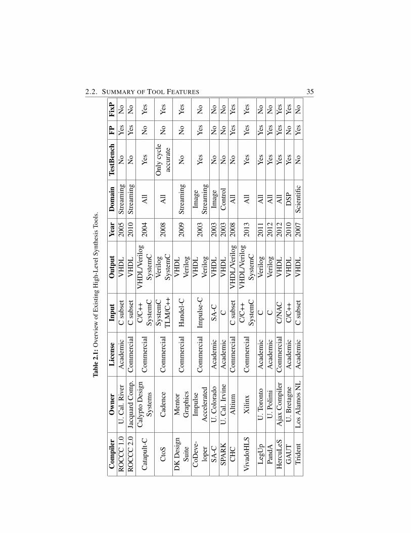
2.2. SUMMARY OF TOOL FEATURES 35Ta
ble
2.1:
Ove
rvie
wof
Exi
stin
gH
igh-
Lev
elSy
nthe
sis
Tool
s.
Com
pile
rO
wne
rL
icen
seIn
put
Out
put
Year
Dom
ain
Test
Ben
chFP
FixP
RO
CC
C1.
0U
.Cal
.Riv
erA
cade
mic
Csu
bset
VH
DL
2005
Stre
amin
gN
oY
esN
oR
OC
CC
2.0
Jacq
uard
Com
p.C
omm
erci
alC
subs
etV
HD
L20
10St
ream
ing
No
Yes
No
Cat
apul
t-C
Cal
ypto
Des
ign
Com
mer
cial
C/C
++V
HD
L/V
erilo
g20
04A
llY
esN
oY
esSy
stem
sSy
stem
CSy
stem
C
Cto
SC
aden
ceC
omm
erci
alSy
stem
CV
erilo
g20
08A
llO
nly
cycl
eN
oY
esT
LM
/C++
Syst
emC
accu
rate
DK
Des
ign
Men
tor
Com
mer
cial
Han
del-
CV
HD
L20
09St
ream
ing
No
No
Yes
Suite
Gra
phic
sV
erilo
gC
oDev
e-Im
puls
eC
omm
erci
alIm
puls
e-C
VH
DL
2003
Imag
eY
esY
esN
olo
per
Acc
eler
ated
Ver
ilog
Stre
amin
gSA
-CU
.Col
orad
oA
cade
mic
SA-C
VH
DL
2003
Imag
eN
oN
oN
oSP
AR
KU
.Cal
.Irv
ine
Aca
dem
icC
VH
DL
2003
Con
trol
No
No
No
CH
CA
ltium
Com
mer
cial
Csu
bset
VH
DL
/Ver
ilog
2008
All
No
Yes
Yes
Viv
adoH
LS
Xili
nxC
omm
erci
alC
/C++
VH
DL
/Ver
ilog
2013
All
Yes
Yes
Yes
Syst
emC
Syst
emC
Leg
Up
U.T
oron
toA
cade
mic
CV
erilo
g20
11A
llY
esY
esN
oPa
ndA
U.P
olim
iA
cade
mic
CV
erilo
g20
12A
llY
esY
esN
oH
ercu
LeS
Aja
xC
ompi
ler
Com
mer
cial
C/N
AC
VH
DL
2012
All
Yes
Yes
Yes
GA
UT
U.B
reta
gne
Aca
dem
icC
/C++
VH
DL
2010
DSP
Yes
No
Yes
Trid
ent
Los
Ala
mos
NL
Aca
dem
icC
subs
etV
HD
L20
07Sc
ient
ific
No
Yes
No
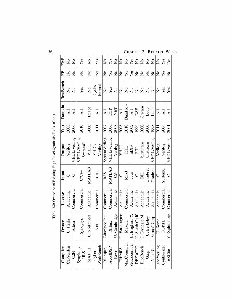
36 CHAPTER 2. RELATED WORKTa
ble
2.2:
Ove
rvie
wof
Exi
stin
gH
igh-
Lev
elSy
nthe
sis
Tool
s.(C
ont)
Com
pile
rO
wne
rL
icen
seIn
put
Out
put
Year
Dom
ain
Test
Ben
chFP
FixP
Cto
Ver
ilog
U.H
aifa
Aca
dem
icC
Ver
ilog
2008
All
No
No
No
C2H
Alte
raC
omm
erci
alC
VH
DL
/Ver
ilog
2006
All
No
No
No
Synp
hony
Syno
psys
Com
mer
cial
C/C
++V
HD
L/V
erilo
g20
10A
llY
esN
oY
esH
LS
Syst
emC
MA
TC
HU
.Nor
thw
est
Aca
dem
icM
AT
LA
BV
HD
L20
00Im
age
No
No
No
Cyb
er-
NE
CC
omm
erci
alB
DL
VH
DL
2011
All
Cyc
le/
Yes
Yes
Wor
kBen
chV
erilo
gFo
rmal
Blu
espe
cB
lueS
pec
Inc.
Com
mer
cial
BSV
Syst
emV
erilo
g20
07A
llN
oN
oN
oA
ccel
DSP
Xili
nxC
omm
erci
alM
AT
LA
BV
HD
L/V
erilo
g20
06D
SPY
esY
esY
esK
iwi
U.C
ambr
idge
Aca
dem
icC
#V
erilo
g20
08.N
ET
No
No
No
CH
iMPS
U.W
ashi
ngto
nA
cade
mic
CV
HD
L20
08A
llN
oN
oN
oM
axC
ompi
ler
Max
eler
Com
mer
cial
Max
JR
TL
2010
Dat
aFlo
wN
oY
esN
oSe
aCuc
umbe
rU
.Bri
gham
Y.A
cade
mic
Java
ED
IF20
02A
llN
oY
esY
esD
EFA
CTO
U.S
outh
Cai
lf.
Aca
dem
icC
RT
L19
99D
SEN
oN
oN
oPi
peR
ench
U.C
arne
gie
M.
Aca
dem
icD
ILbi
tstr
eam
2000
Stre
amN
oN
oN
oG
arp
U.B
erke
ley
Aca
dem
icC
subs
etbi
tstr
eam
2000
Loo
pN
oN
oN
oN
apa-
CSa
rnof
fCor
p.A
cade
mic
Csu
bset
VH
DL
/Ver
ilog
1998
Loo
pN
oN
oN
ogc
c2ve
rilo
gU
.Kor
eaA
cade
mic
CV
erilo
g20
11A
llN
oN
oN
oC
ynth
esiz
erFO
RT
EC
omm
erci
alSy
stem
CV
erilo
g20
04A
llY
esY
esY
eseX
Cite
YE
xplo
ratio
nsC
omm
erci
alC
VH
DL
/Ver
ilog
2001
All
Yes
No
Yes
2.3. CONCLUSION 37
the input language has to be restricted, modified or extended. For example,SA-C, DK Design Suite, Impulse-C, CyberWorkbench, BlueSpec, PipeRenchor Garp all limit in some way the input language by not accepting for instancepointers or control statements. Furthermore, some tools require the additionof specific code/language constructs to convey specific platform information,such as PipeRench or Napa-C. This increases the time required to learn howto use the tool and to transform the existing HLL code to an accepted syntaxbefore any useful output can be generated. DWARV does not require any ad-ditional language constructs and can generate code from (almost) any functionas it is.
Another important difference is that some tools are available as integrated com-pilers in larger design environments (e.g., CHC, C2H, Synphony HLS or Ac-celDSP), most of which are targeted at the hardware designer and not the soft-ware developer. That tool is then very hard to use without actually having hard-ware design knowledge. Considering the scenario assumed in this work wherea software designer moves software to hardware to accelerate specific com-putations (i.e., only a particular function needs to be accelerated), designingthe whole (hardware) system is inconvenient and limited to a number of hard-ware designers. These frameworks are thus not intended for the vast majorityof software programmers as DWARV’s target audience is, but it is intendedto obtain (fast) hardware IPs by a hardware designer performing system-wideDSE before he can choose a solution for its ASIC.
Finally, some of the (early) tools were based on immature research compilerframeworks which led to the their abandonment. We list ROCCC1.0, Napa-C, Garp or AccelDSP. Furthermore, this underlying compiler framework canplay a very big role in the high-level language coverage and the compiler opti-mization support of a hardware compiler. The latest version of DWARV differsfrom all previous tools by using CoSy compiler framework. This highly modu-lar and extensible framework offers both lowering (i.e., high-level to low-levelconstruct mapping) transformations so that all HLL constructs can be acceptedas well as support for automatic selection of which compiler optimizations tobe applied removing the user need of performing this selection manually at thecommand line (or in a GUI).
2.3 Conclusion
In this chapter, we described a number of academic and commercial high-levelsynthesis compilers. Although we could observe an increase in the amount of
38 CHAPTER 2. RELATED WORK
both research tools and commercial products available, especially in the lastthree to four years, our evaluation of these tools showed that knowledge onhow to generate efficient hardware accelerators is still not mature enough toreplace the manual design completely. As a result, the need of research in howto design hardware compilers is justified. Furthermore, the last version of thecompiler at the time of writing this thesis, i.e., DWARV3.0, is different in atleast one aspect from the related compilers as shown in the previous section.
Note.
The content of this chapter was submitted as part of the following publication:
R. Nane, V.M. Sima, K.L.M. Bertels, A Survey of High-Level Synthesis Toolsand Comparison with DWARV 3.0, Submitted to IEEE Transactions onComputer-Aided Design of Integrated Circuits and Systems, April 2014.
3Background Work
IN this chapter, we present the environment in which the work pre-sented in this dissertation was done. First, we describe the Delft Work-bench tool-chain, which consists of several tools to enable automated
Hardware/Software (HW/SW) co-design. Subsequently, we present in detailthe Molen machine organization, we show the synthesis and verification flowsused to validate generated accelerators, and we discuss important similaritiesand differences between software and hardware compilers. Finally, we presentthe first version of the DWARV compiler that provided the inspiration for thecurrent version, we describe the CoSy compiler framework used to constructDWARV3.0, and we give a simple C-to-FPGA example showing the tool-flow.
3.1 Introduction
The Delft Workbench (DWB) [12] is a semi-automatic tool chain for inte-grated HW/SW co-design. The goal is to facilitate heterogeneous computingand to enable fast Design Space Exploration (DSE) on Molen type heteroge-neous systems by automating, where possible, the profiling, estimation, map-ping and implementation processes that are part of the development process.One of the tools developed in the scope of this workbench was the DWB Au-tomated Reconfigurable VHDL (DWARV) [97] generator. As explained in theintroduction, DWARV takes parts (i.e., functions1) of high-level programs andtransforms them into hardware accelerators to be run on a Molen machine. Al-though the DWB targets implementations of Molen on Xilinx boards becauseof its availability and expertise, any other type of heterogeneous computingplatform could have been used instead. For example, the Convey [19] HCmachines can be considered instantiations of the Molen machine organization
1functions and kernels are used interchangeably throughout the text
39
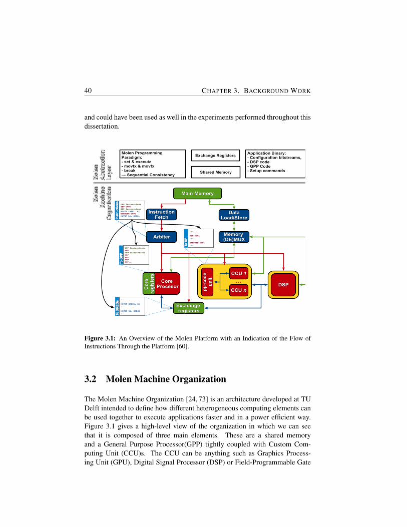
40 CHAPTER 3. BACKGROUND WORK
and could have been used as well in the experiments performed throughout thisdissertation.
Main MemoryMain Memory
Exchange Exchange registersregisters
ArbiterArbiter
GPP InstructionsSET CCU1GPP InstructionsMOVET XREG1, R1EXECUTE CCU1MOVEF R1, XREG1
Inst
ruct
ion
sIn
stru
ctio
ns
GPP InstructionsNOPGPP InstructionsNOPNOPNOPNOP...To
GP
PTo
GP
P
...
SET CCU1...
EXECUTE CCU1...To
RP
To R
P
...
MOVET XREG1, R1...
MOVEF R1, XREG1...To
XR
EG
sTo
XR
EG
s
Core Core ProcesorProcesorC
ore
C
ore
re
gis
ters
reg
iste
rs
Memory Memory (DE)MUX(DE)MUX
ρμ
-co
de
ρμ
-co
de
un
itu
nit
CCU CCU 11
CCU CCU nn
...DSPDSP
InstructionInstructionFetchFetch
DataDataLoad/StoreLoad/Store
Molen Programming Paradigm:- set & execute- movtx & movfx- break→ Sequential Consistency
Exchange Registers
Shared Memory
Application Binary:- Configuration bitstreams,- DSP code- GPP Code- Setup commands
Mo
len
Mo
len
Ab
stra
ctio
nA
bst
ract
ion
Lay
erL
ayer
Mo
len
Mo
len
Mac
hin
eM
ach
ine
Org
aniz
atio
nO
rgan
izat
ion
Figure 3.1: An Overview of the Molen Platform with an Indication of the Flow ofInstructions Through the Platform [60].
3.2 Molen Machine Organization
The Molen Machine Organization [24, 73] is an architecture developed at TUDelft intended to define how different heterogeneous computing elements canbe used together to execute applications faster and in a power efficient way.Figure 3.1 gives a high-level view of the organization in which we can seethat it is composed of three main elements. These are a shared memoryand a General Purpose Processor(GPP) tightly coupled with Custom Com-puting Unit (CCU)s. The CCU can be anything such as Graphics Process-ing Unit (GPU), Digital Signal Processor (DSP) or Field-Programmable Gate

3.2. MOLEN MACHINE ORGANIZATION 41
Array (FPGA) based kernels. The Molen organization has been successfullyimplemented and demonstrated using DSP and FPGA kernels.
This setup allows taking advantage of inherent parallelism in applications fromvarious domains, by allowing to move computationally intensive parts of codeto hardware (CCU) while keeping the rest of the application in software (GPP).The Molen supporting tool-chain (i.e., DWB) performs in this respect the fol-lowing tasks: searches for pragma annotations in the source application code,usually set manually by the user or automatically by a previously running pro-filing tool, invokes the Molen primitives that deal with loading the function pa-rameter values in the eXchange Register (XREG)s, place from where the CCUcan access its input values, and finally, calls the actual function that will runin the FPGA. Depending on the data dependency analysis this can be block-ing or non-blocking. The CCU can be the hardware generated by invokingthe DWARV compiler described in Chapter 4. This setup enables DSE byallowing the user to perform and evaluate various configurations of HW/SWpartitioning.
To exploit the Molen machine organization efficiently, the Molen program-ming paradigm [91] was devised. The concepts defined by this paradigm areshown in the upper part of Figure 3.1. They address the inherent problemcaused by the flexibility of reconfigurable computing where different instruc-tions can be accommodated, and, as a result, there is no fixed instruction set.The solution to this issue consisted in a one-time extension of the (Polymor-phic) Instruction Set Architecture (πISA) such that any number of processorextensions with a variable number of arguments can be supported. This exten-sion was implemented by the following instructions:
• SET instruction configures (i.e., loads) the computation on the process-ing element (e.g., FPGA).
• MOVET/MOVEF instructions are used to transfer data to and from theprocessing element’s local memory.
• EXECUTE instruction gives the start signal for the processing elementto begin execution.
• BREAK instruction polls the processing element to check whether exe-cution has finished.
The Molen machine organization implements a parallel execution model, andits supporting Molen programming paradigm is compatible with parallel pro-gramming frameworks such as OpenMP [69]. As a consequence, it is very

42 CHAPTER 3. BACKGROUND WORK
important to note that sequential consistency (i.e., execution on the heteroge-neous platform produces the same results as when the original program wouldhave been executed sequentially on a General-Purpose Processor (GPP)) is en-forced by the above instructions. This is accomplished by adopting the sharedmemory computational model.
Profiling andProfiling andCost EstimationCost Estimation
Profiling andProfiling andCost EstimationCost Estimation
HW/SW PartitioningHW/SW Partitioningand Mappingand Mapping
HW/SW PartitioningHW/SW Partitioningand Mappingand Mapping
Graph TransformationsGraph Transformationsand Optimizationsand Optimizations
Graph TransformationsGraph Transformationsand Optimizationsand Optimizations
Runtime SupportRuntime SupportRuntime SupportRuntime Support
HW area
hotspots
power
memory
SWSWHWHW
FPGADSPetc.
GPP
Designer
pushl %ebpmovl %esp,%ebpmovl 8(%ebp),%ecxmovl $1,%eax
unsigned f(unsigned n){ int i, result = 1; for(i=1; i<n; i++) { result *= i; } return result;}
Application GCC
#pragma area stratixV 560#pragma gprof 90#pragma memory 0 #pragma area virtex5 700unsigned f(unsigned n){...
#pragma map generate_hw#pragma map virtex5unsigned f(unsigned n){...
unsigned f(unsigned n) { register int i; unsigned result = 1; for(i=2; i<=n; i+=2) { result *= i*(i+1); } if(i==(n-1)) result *= i; return result;}
HardwareHardwareGenerationGeneration
HardwareHardwareGenerationGeneration
RetargetableRetargetableCompilationCompilation
RetargetableRetargetableCompilationCompilation
Quipumodel
executablebinary
Feedback to earlier stages
<?xml version="1.0"?><ORGANIZATION> <HARDWARE> <NAME>ML510</NAME> <FUNCTIONAL_COMPONENT> <NAME>PPC</NAME> <TYPE>GPP</TYPE> <MASTER>YES</MASTER> <FREQUENCY>200</FREQUENCY> </FUNCTIONAL_COMPONENT> <FUNCTIONAL_COMPONENT> <NAME>VIRTEX5</NAME> <TYPE>FPGA</TYPE> <MASTER>NO</MASTER> <FREQUENCY>100</FREQUENCY>...A
rch
itec
ture
Des
crip
tio
nA
rch
itec
ture
Des
crip
tio
n
Ori
gin
alO
rig
inal
An
no
tate
dA
nn
ota
ted
Map
ped
Map
ped
Tran
sfo
rmed
Tran
sfo
rmed
DWARV
Figure 3.2: Overview of the Delft Workbench Tool-Chain [60].
3.3 Delft Workbench Tool-Chain
Figure 3.2 shows the complete design flow within the DWB. The first processin the flow is the Profiling and Cost Estimation. The objective is to identifythe computational intensive parts of an application that are good candidates forhardware acceleration. Furthermore, design data such as the maximum perfor-mance improvement, resource occupation and power requirements is gatheredto drive the subsequent partitioning, mapping and optimization stages. HW/SWPartitioning and Mapping uses the previous acquired design characteristics topartition the original application into different parts and map them onto the dif-ferent computational elements available on the heterogeneous computing plat-
3.4. BACK-END WORK FLOWS 43
form. Graph Transformations and Optimizations processes are used to trans-form the application code to a form suitable for hardware implementation. Forexample, parts of the graph can be duplicated or factored out depending on theavailable hardware resources. Retargetable Compilation is an important stepin the context of the complete tool-chain. It is here that a retargetable compilergenerates code for the embedded GPP and combines generated bitstreams forFPGAs, DSPs, etc., into a final Executable and Linkable Format (ELF) file thatcan be executed on the heterogeneous platform. The generation of bitstreamsis done with technology dependent synthesis tools, but Hardware DescriptionLanguage (HDL) code required as input by these synthesis tools is obtainedin the Hardware Generation stage. DWARV is the compiler that generatessuch HDL (i.e., VHDL) from High-Level Language (HLL) (i.e., C) code andis, therefore, executed in this stage. Finally, Run-time Support is intendedto offer support for (dynamic) system reconfiguration and management in amulti-tasking environment.
3.4 Back-end Work Flows
There are two possible work flows: the synthesis flow and the simulation flow.The first one can be used for fast prototyping and mapping exploration, whilethe later is used to verify the generated hardware kernel automatically beforerunning it on the actual hardware. Both flows rely on same high-level concepts.
3.4.1 Synthesis Flow
The synthesis flow is presented in Figure 3.3. The input of the flow is C codewhile the output is an executable binary for a specific platform (for example theML510 platform). The blue boxes represent the tools/components of the DWBtool-chain while the grey components represent external components like thegcc compiler or the Xilinx tool-chain. The green boxes show intermediary filesrelated to the application.
The purpose of the frontend is to partition and map the application in prepa-ration to the invocation of the back-end compilers. This was illustrated anddescribed in the previous section (3.3). Then, each part of the application goesto each back-end compiler (e.g., for the ML510 platform). The platform com-piler will directly generate object code in the ELF format. For the part thathas to go to the FPGA, Delft Workbench Automated Reconfigurable VHDLGenerator (DWARV) is invoked first to generate the VHDL. The generated
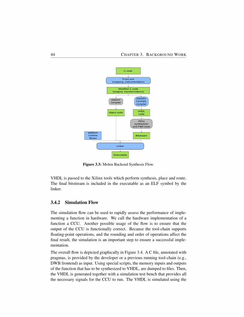
44 CHAPTER 3. BACKGROUND WORK
C code
Modified C code(pragma, transformations)
Front end(mapping, instrumentation)
platormcompiler
object code
Linker
DWARVC2VHDLcompiler
Xilinxsynthesizer
and P&R tools
VHDLcode
Bitstreamplatformruntimelibrary
Executable
Figure 3.3: Molen Backend Synthesis Flow.
VHDL is passed to the Xilinx tools which perform synthesis, place and route.The final bitstream is included in the executable as an ELF symbol by thelinker.
3.4.2 Simulation Flow
The simulation flow can be used to rapidly assess the performance of imple-menting a function in hardware. We call the hardware implementation of afunction a CCU. Another possible usage of the flow is to ensure that theoutput of the CCU is functionally correct. Because the tool-chain supportsfloating-point operations, and the rounding and order of operations affect thefinal result, the simulation is an important step to ensure a successful imple-mentation.
The overall flow is depicted graphically in Figure 3.4. A C file, annotated withpragmas, is provided by the developer or a previous running tool-chain (e.g.,DWB frontend) as input. Using special scripts, the memory inputs and outputsof the function that has to be synthesized to VHDL, are dumped to files. Then,the VHDL is generated together with a simulation test bench that provides allthe necessary signals for the CCU to run. The VHDL is simulated using the

3.5. SOFTWARE VS. HARDWARE COMPILERS 45
C applications, with kernels and calls to
kernel annotated
VHDL file
Generate VHDL(using DWARV)
Instrument application(using Molen compiler)
Instrumented executable for x86
For each call to a hardware kernel,
dumped input and output data
Dumped output data
Simulate the VHDL using the input data dumped
Compare output data from software with output data from hardware simulation
Execute the application
Figure 3.4: Simulation Flow for Verifying DWARV Generated VHDL Kernels.
memory inputs, and the outputs are also dumped in a file. The final step is tocompare the outputs obtained from software with the outputs obtained fromhardware.
An important note is that all memory locations that are sent through pointerparameters to the CCU-s must be allocated through malloc function calls (nolocal or global variables). If the function parameters are arrays (and thus, thecompiler can determine their size at compile time), any memory location canbe sent to the function.
3.5 Software vs. Hardware Compilers
Different books are available on how to write a compiler such as [37]. For thepurposes of this section, it is sufficient to highlight that a compiler is composedof several main passes that transforms the input high-level language code to aformat accepted by the target machine. We define a software compiler as acompiler that transforms a HLL to assembly type instructions, whereas a hard-ware compiler is one that transforms a HLL code to an equivalent HDL repre-sentation. The first two steps in any compiler are to scan and parse the input
46 CHAPTER 3. BACKGROUND WORK
file. After these steps, an Intermediate Representation (IR) form is created thatenables transformations and optimizations to be performed on the original in-put code. Important transformations are lowering transformations, Static Sin-gle Assignment (SSA), Data Dependency Graph (DDG) construction, instruc-tion selection, instruction scheduling and register allocation. Important opti-mizations include Common Subexpression Elimination (CSE), constant fold-ing and propagation, dead code elimination, if-conversion, loop unrolling, looppipelining, polyhedral analysis and peephole optimizations such as strength re-duction. Finally, the last step is the generation of code. This process outputsin a file the schedule obtained by including all the previous information gath-ered and by printing architectural dependent strings representing the instruc-tion rules matched in the instruction selection step.
Building a hardware compiler is not very different than building a softwarecompiler. In principle, all above steps can be applied. However, because on(raw) (re)configurable hardware the number of resources is not fixed, and, assuch, we can (to some extent) accommodate as many resources as required,we have to change how some of the traditional software compiler passes areapplied in the context of hardware generation. Although this kind of analy-sis can apply to various compiler transformations and optimizations, for thescope of this section, we discuss here only a few: CSE, if-conversion, registerallocation, operation chaining and memory spaces.
CSE is an optimization that computes common expressions once, places theresult in a register or memory, and refers this location for subsequent uses.The advantage is that we can save time and resources by not computing theexpression again because loading the already computed value is faster on aCentral Processing Unit (CPU). However, for hardware generation this has tobe carefully considered. That is, if the allocated register and the expressionwhere this replaced expression should be used is not in the immediate prox-imity of the calculation, the routing to that place might actually decrease thedesign frequency. Therefore, applying this optimization is not always usefulin High-Level Synthesis (HLS). In this case, replacing only a particular subsetand recomputing the expression for others to enforce a better locality of theoperations, would provide better results. If-conversion provides the oppositescenario, which will be described in detail in Chapter 7.
Register allocation is a highly important transformation that should be treateddifferently. Because in hardware we have an unlimited number of registers, theallocation of variables to these can be considered simpler. That is, wheneverwe need a register, we allocate a new one. However, if the generated design
3.6. DWARV 1.0 47
does not fit into a given area constraint, the register allocation becomes moredifficult to solve because it is not easy to decide how many registers shouldbe removed and which ones in order to successfully implement the generateddesign on the given area. Operation chaining is an optimization that is speciallydesigned for hardware compilers. Because in hardware the clock period isuser defined, we use this optimization to schedule dependent instructions inthe same clock cycle if their cumulative execution time is less than the givenclock cycle time. This operation optimizes significantly the wall clock time(i.e., execution time) of the entire function implemented on hardware. Finally,memory spaces can be allocated for different array parameters so that multiplememory operations can be performed in the same cycle.
3.6 DWARV 1.0
DWARV’s [97] first implementation was based on the SUIF compiler frame-work from Stanford university [89]. The framework provided methods to cre-ate an IR from a HLL program and passes/mechanisms to access that IR toprocess the data in a way most suitable for the compiler developer. However,being a research project, the SUIF framework had many drawbacks such as:
• No longer supported and the documentation was scarce.
• No optimization passes available.
• No dependency analysis and aliasing disambiguation available.
• No extendible IR.
Furthermore, given the fact that no lowering transformations (i.e., from high-to low-level constructs, e.g., from switch statement to simple compare-jumpstatements) were available in SUIF, not all syntax was supported by DWARV1.0. Tables 3.1 and 3.2 list all restrictions available in the initial version ofDWARV. Given the many drawbacks and the missing features, especially giventhe fact that development of SUIF was abandoned and it become unsupported,a change to another compiler framework was necessary. Nevertheless, despiteall the drawbacks, this first compiler inspired the FSM plus Datapath compu-tational model along with the hardware accelerator VHDL file structure alsoused in the second version (see Chapter 4).
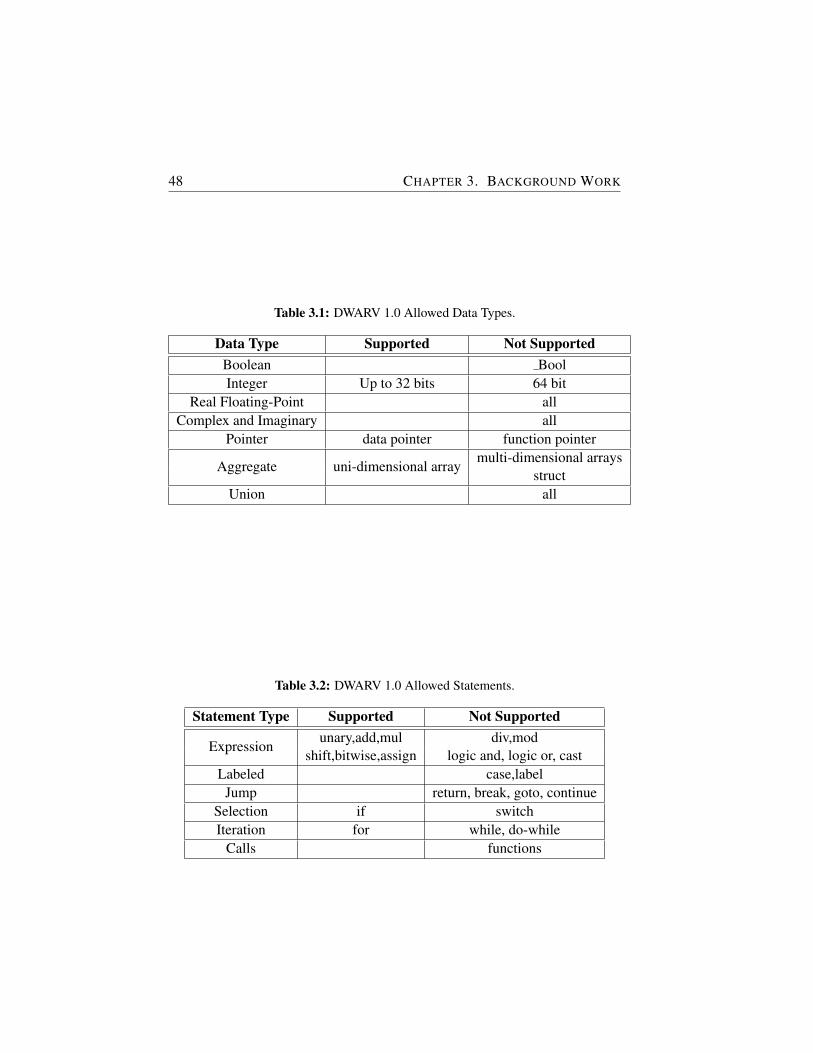
48 CHAPTER 3. BACKGROUND WORK
Table 3.1: DWARV 1.0 Allowed Data Types.
Data Type Supported Not SupportedBoolean BoolInteger Up to 32 bits 64 bit
Real Floating-Point allComplex and Imaginary all
Pointer data pointer function pointer
Aggregate uni-dimensional arraymulti-dimensional arrays
structUnion all
Table 3.2: DWARV 1.0 Allowed Statements.
Statement Type Supported Not Supported
Expressionunary,add,mul div,mod
shift,bitwise,assign logic and, logic or, castLabeled case,label
Jump return, break, goto, continueSelection if switchIteration for while, do-while
Calls functions
3.7. COSY COMPILER FRAMEWORK 49
For the new version of DWARV, four candidate compiler frameworks wereconsidered. LLVM was the first one, but because, at that time, the frame-work was not mature enough (e.g., frontend integration was not easy), it wasnot selected. gcc was another candidate, however, this framework was goingthrough major changes in the IR from version 4.5; therefore, it was not consid-ered stable. ROSE is a compiler framework that deals only with high-levels ofabstraction, and; therefore, it is used only for HLL to HLL compilers. Further-more, it does not include backend code generator features that are required fora compiler generating low-level code. Finally, the last candidate was the CoSycompiler framework. Due to its maturity, robust, and extendible features, cou-pled with the close collaboration with the ACE company in the REFLECT [70]project, this framework was selected to reimplement the DWARV 1.0 compiler.
3.7 CoSy Compiler Framework
The CoSy [26] compiler development system is a commercial compiler con-struction system licensed by ACE Associated Compiler Experts. The develop-ment system is composed of several tools building on innovative concepts thatallow the user to build and extend a compiler easily. The central concept inCoSy is the Engine that can be regarded as an abstraction of a particular trans-formation or optimization algorithm. The framework includes a total numberof 208 engines that target different parts of the compilation flow, from the fron-tend (i.e., code parsing and IR creation) processing, high-level (e.g., loop op-timization, algebraic optimizer, code analysis, lowering transformations) andlow-level (e.g., register allocation, instruction selection and scheduling) trans-formations and optimizations to backend code generation template rules usedin the final emission step. The general functionality of (custom user-defined)engines can be programmed in C or in C++ while for IR specific initializationsand assignments, CoSy-C, an extension of the C-language, is used.
Figure 3.5 depicts graphically the connections between CoSy concepts thatcombined form a CoSy compiler. Each engine accesses the IR through specificViews generated in the Supervisor during compiler build time. This is possi-ble because each engine contains a list of parameters that are typed handleson IR fragments. The IR is described in a CoSy specific description language,i.e., full-Structure Definition Language (fSDL), and contains the data structureson which engines operate. The strength of this language is its distributed na-ture in the sense that multiple definitions of the same data structure augmenteach other. This allows to specify IR extensions easily and locally in each

50 CHAPTER 3. BACKGROUND WORK
C/C++Front‐en
Supervisor
CustomEngines
IRCompiler IRCompilerConfiguration
Scheduler
CodeAnalys
+nd
LoopOptimizer
R AlgebraicViR g
OptimizerView
RegisterAllocator
esis
Figure 3.5: CoSy Framework Elements: Supervisor, Engines, Views and IR.
engine by (re)defining and extending the target data structure in the engine’s〈engine name〉.sdl file. From this file, specific views are inferred based on theaccess rights defined for each data structure’s operator fields (e.g., new, read,write, walk, etc). That is, a view can be thought of as a special set of acces-sor and mutator method(s) for a data structure. These concepts improve theproductivity of the compiler designer because they enforce at compile time theclear separation between engines, thus making a CoSy based compiler verymodular by nature.
The control and data flow through the compiler is coded in *.edl files thatare written in another CoSy-specific language, the Engine Description Lan-guage (EDL). This language provides mechanisms to form an engine classhierarchy by defining composite engine classes as groups of engines. Fur-thermore, it allows the user to specify different interaction schemes betweenengines. For example, a particular set of engines can be run sequentially, ina pipeline, in parallel or in a loop. A supervisor is generated from the EDLand fSDL specifications. Therefore, it implements the control and data flowthrough the compiler and protects the IR against conflicting accesses. To gen-erate code, the supervisor uses the instantiated (i.e., implemented) versionsof CoSy template rules (e.g., mirPlus(rs1:register;rs2:register) -〉 rd:register)defined in *.cgd files. A compiler is composed of the generated supervisor in-stantiated in a small main program that reads command line options, processesthem if necessary, and passes them on to the supervisor. Finally, below thesupervisor we find the independent codes of all simple engines that form thebulk of the compiler.
Therefore, the main strength of the framework is that it consist of loosely inte-
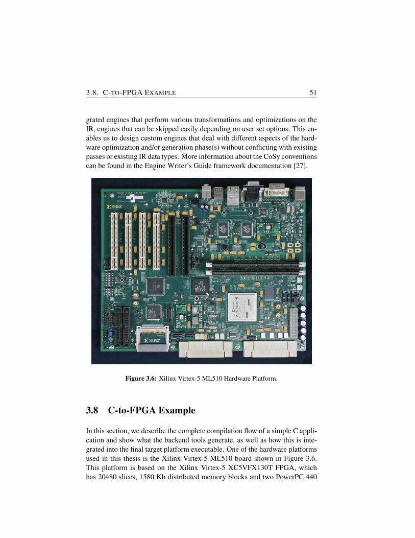
3.8. C-TO-FPGA EXAMPLE 51
grated engines that perform various transformations and optimizations on theIR, engines that can be skipped easily depending on user set options. This en-ables us to design custom engines that deal with different aspects of the hard-ware optimization and/or generation phase(s) without conflicting with existingpasses or existing IR data types. More information about the CoSy conventionscan be found in the Engine Writer’s Guide framework documentation [27].
Figure 3.6: Xilinx Virtex-5 ML510 Hardware Platform.
3.8 C-to-FPGA Example
In this section, we describe the complete compilation flow of a simple C appli-cation and show what the backend tools generate, as well as how this is inte-grated into the final target platform executable. One of the hardware platformsused in this thesis is the Xilinx Virtex-5 ML510 board shown in Figure 3.6.This platform is based on the Xilinx Virtex-5 XC5VFX130T FPGA, whichhas 20480 slices, 1580 Kb distributed memory blocks and two PowerPC 440

52 CHAPTER 3. BACKGROUND WORK
FPGA (XC5VFX130T)
PPC 440
DD
R (
2 G
B)
Memory controller
MOLEN
Ethernet UART
BR
AM
(64
k)
Reconfigurable area
BR
AM
(64
k)B
RA
M (
64k)
BR
AM
(64
k)B
RA
M (
64k)
DMA
ICAP
Control signals
FPU
SysACE
PLB
Slot 1
Slot 2
Slot 3
Slot 4
Slot 5
DCMClocksignals
Reconf.signals
Figure 3.7: Molen Implementation on the ML510 Hardware Platform.
(PPC440) processor hard cores embedded that run at a maximum of 400 MHz.
To use this platform, the Molen machine organization was implemented usinga custom Fabric Coprocessor Module (FCM), shown in the simplified plat-form schematic in Figure 3.7 as the Molen box. The FCM is designed to en-able custom instruction extensions of the PPC440 processor’s Instruction SetArchitecture (ISA). Newly added instructions are recognized in the decodephase by the PPC440 processor’s Auxiliary Processor Unit (APU) (not shownin the figure) as custom instructions, and, subsequently, dispatched to the FCMunit for the execution stage. In Figure 3.7, we see five reconfigurable slots (slotone to five) reserved for custom accelerators. Each of these areas can be in-dependently reconfigured and executed at run-time. This is not a limitation ofthe Molen architecture, but merely a design choice considering the hardwarearea available on this FPGA board and the reconfigurability requirement.
To show how applications can be accelerated on the ML510 platform usingreconfigurable logic, we use the simple C-application given in Listing 3.1i).This is composed of some arbitrary code, that will keep running on the PPC440processor, followed by a call to the absval arr function, which is the targetfunction for acceleration. To mark that this function should be implementedin hardware, we annotate its call with a pragma directive. This annotation
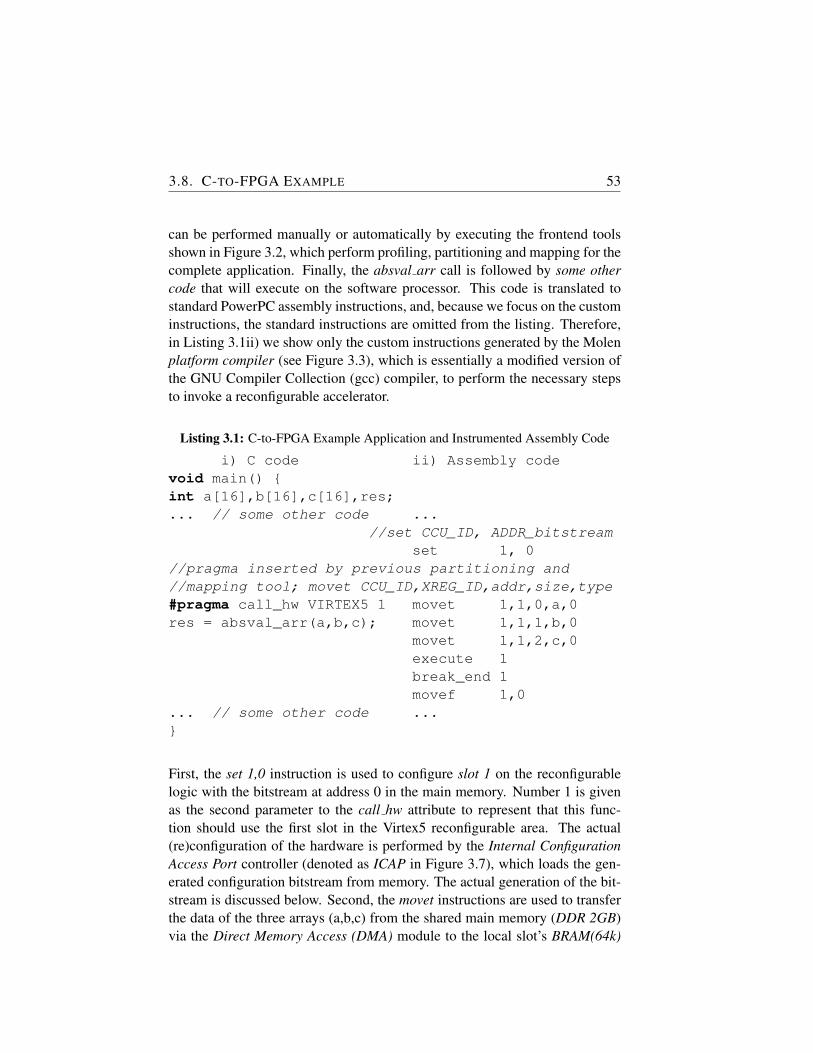
3.8. C-TO-FPGA EXAMPLE 53
can be performed manually or automatically by executing the frontend toolsshown in Figure 3.2, which perform profiling, partitioning and mapping for thecomplete application. Finally, the absval arr call is followed by some othercode that will execute on the software processor. This code is translated tostandard PowerPC assembly instructions, and, because we focus on the custominstructions, the standard instructions are omitted from the listing. Therefore,in Listing 3.1ii) we show only the custom instructions generated by the Molenplatform compiler (see Figure 3.3), which is essentially a modified version ofthe GNU Compiler Collection (gcc) compiler, to perform the necessary stepsto invoke a reconfigurable accelerator.
Listing 3.1: C-to-FPGA Example Application and Instrumented Assembly Code
i) C code ii) Assembly codevoid main() {int a[16],b[16],c[16],res;... // some other code ...
//set CCU_ID, ADDR_bitstreamset 1, 0
//pragma inserted by previous partitioning and//mapping tool; movet CCU_ID,XREG_ID,addr,size,type#pragma call_hw VIRTEX5 1 movet 1,1,0,a,0res = absval_arr(a,b,c); movet 1,1,1,b,0
movet 1,1,2,c,0execute 1break_end 1movef 1,0
... // some other code ...}
First, the set 1,0 instruction is used to configure slot 1 on the reconfigurablelogic with the bitstream at address 0 in the main memory. Number 1 is givenas the second parameter to the call hw attribute to represent that this func-tion should use the first slot in the Virtex5 reconfigurable area. The actual(re)configuration of the hardware is performed by the Internal ConfigurationAccess Port controller (denoted as ICAP in Figure 3.7), which loads the gen-erated configuration bitstream from memory. The actual generation of the bit-stream is discussed below. Second, the movet instructions are used to transferthe data of the three arrays (a,b,c) from the shared main memory (DDR 2GB)via the Direct Memory Access (DMA) module to the local slot’s BRAM(64k)
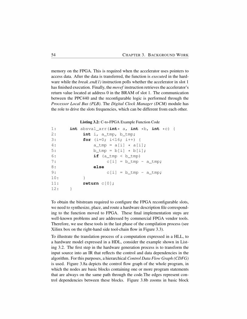
54 CHAPTER 3. BACKGROUND WORK
memory on the FPGA. This is required when the accelerator uses pointers toaccess data. After the data is transferred, the function is executed in the hard-ware while the break end(1) instruction polls whether the accelerator in slot 1has finished execution. Finally, the movef instruction retrieves the accelerator’sreturn value located at address 0 in the BRAM of slot 1. The communicationbetween the PPC440 and the reconfigurable logic is performed through theProcessor Local Bus (PLB). The Digital Clock Manager (DCM) module hasthe role to drive the slots frequencies, which can be different from each other.
Listing 3.2: C-to-FPGA Example Function Code
1: int absval_arr(int* a, int *b, int *c) {2: int i, a_tmp, b_tmp;3: for (i=0; i<16; i++) {4: a_tmp = a[i] * a[i];5: b_tmp = b[i] * b[i];6: if (a_tmp < b_tmp)7: c[i] = b_tmp - a_tmp;8: else9: c[i] = b_tmp - a_tmp;10: }11: return c[0];12: }
To obtain the bitstream required to configure the FPGA reconfigurable slots,we need to synthesize, place, and route a hardware description file correspond-ing to the function moved to FPGA. These final implementation steps arewell-known problems and are addressed by commercial FPGA vendor tools.Therefore, we use these tools in the last phase of the compilation process (seeXilinx box on the right-hand side tool-chain flow in Figure 3.3).
To illustrate the translation process of a computation expressed in a HLL, toa hardware model expressed in a HDL, consider the example shown in List-ing 3.2. The first step in the hardware generation process is to transform theinput source into an IR that reflects the control and data dependencies in thealgorithm. For this purposes, a hierarchical Control Data Flow Graph (CDFG)is used. Figure 3.8a depicts the control flow graph of the whole program, inwhich the nodes are basic blocks containing one or more program statementsthat are always on the same path through the code.The edges represent con-trol dependencies between these blocks. Figure 3.8b zooms in basic block
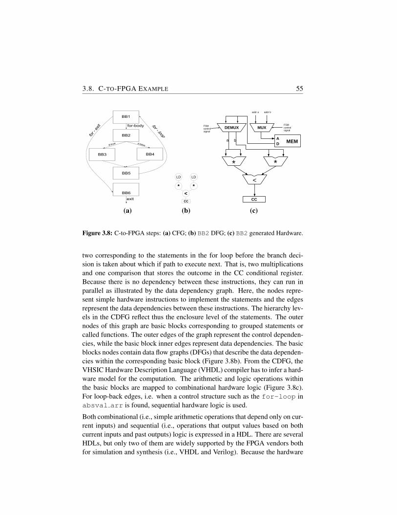
3.8. C-TO-FPGA EXAMPLE 55
BB1
BB2
BB3 BB4
BB5
BB6
for -
exit
exit
for - loop
for-body
if-falseif-true
LD
CC
* *
LD
<CC
*
<
*
MEM A D
MUXFSM controlsignal
addr a addr b
DEMUXFSM control signal
a b
(a) (b) (c)
Figure 3.8: C-to-FPGA steps: (a) CFG; (b) BB2 DFG; (c) BB2 generated Hardware.
two corresponding to the statements in the for loop before the branch deci-sion is taken about which if path to execute next. That is, two multiplicationsand one comparison that stores the outcome in the CC conditional register.Because there is no dependency between these instructions, they can run inparallel as illustrated by the data dependency graph. Here, the nodes repre-sent simple hardware instructions to implement the statements and the edgesrepresent the data dependencies between these instructions. The hierarchy lev-els in the CDFG reflect thus the enclosure level of the statements. The outernodes of this graph are basic blocks corresponding to grouped statements orcalled functions. The outer edges of the graph represent the control dependen-cies, while the basic block inner edges represent data dependencies. The basicblocks nodes contain data flow graphs (DFGs) that describe the data dependen-cies within the corresponding basic block (Figure 3.8b). From the CDFG, theVHSIC Hardware Description Language (VHDL) compiler has to infer a hard-ware model for the computation. The arithmetic and logic operations withinthe basic blocks are mapped to combinational hardware logic (Figure 3.8c).For loop-back edges, i.e. when a control structure such as the for-loop inabsval arr is found, sequential hardware logic is used.
Both combinational (i.e., simple arithmetic operations that depend only on cur-rent inputs) and sequential (i.e., operations that output values based on bothcurrent inputs and past outputs) logic is expressed in a HDL. There are severalHDLs, but only two of them are widely supported by the FPGA vendors bothfor simulation and synthesis (i.e., VHDL and Verilog). Because the hardware
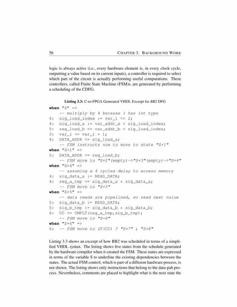
56 CHAPTER 3. BACKGROUND WORK
logic is always active (i.e., every hardware element is, in every clock cycle,outputting a value based on its current inputs), a controller is required to selectwhich part of the circuit is actually performing useful computations. Thesecontrollers, called Finite State Machine (FSM)s, are generated by performinga scheduling of the CDFG.
Listing 3.3: C-to-FPGA Generated VHDL Excerpt for BB2 DFG
when "S" =>-- multiply by 4 because i has int type
4: sig_load_index := var_i << 2;4: sig_load_a := var_addr_a + sig_load_index;5: reg_load_b <= var_addr_b + sig_load_index;3: var_i <= var_i + 1;4: DATA_ADDR <= sig_load_a;
-- FSM instructs now to move to state "S+1"when "S+1" =>5: DATA_ADDR <= reg_load_b;
-- FSM move to "S+2"(empty)->"S+3"(empty)->"S+4"when "S+4" =>
-- assuming a 4 cycles delay to access memory4: sig_data_a := READ_DATA;4: reg_a_tmp <= sig_data_a * sig_data_a;
-- FSM move to "S+5"when "S+5" =>
-- data reads are pipelined, so read next value5: sig_data_b := READ_DATA;5: sig_b_tmp := sig_data_b * sig_data_b;6: CC <= CMPLT(reg_a_tmp,sig_b_tmp);
-- FSM move to "S+6"when "S+6" =>6: -- FSM move to IF(CC) ? "S+7" ; "S+8"
Listing 3.3 shows an excerpt of how BB2 was scheduled in terms of a simpli-fied VHDL syntax. The listing shows five states from the schedule generatedby the hardware compiler when it created the FSM. These states are expressedin terms of the variable S to underline the existing dependencies between thestates. The actual FSM control, which is part of a different hardware process, isnot shown. The listing shows only instructions that belong to the data-pah pro-cess. Nevertheless, comments are placed to highlight what is the next state the
3.8. C-TO-FPGA EXAMPLE 57
FSM will take and when. Furthermore, the number in the beginning of the linerefers to the actual C-code line in Listing 3.2 and is intended to immediatelyvisualize how C-code constructs are mapped to VHDL specifications. Finally,variables preceded by var and reg are registered, whereas those preceded bysig denote that only wires are inferred (i.e., no register is required to store theirvalue) because they are used immediately in the same cycle. As a result, theirvalue does not need to be remembered. DATA ADDR and READ DATA areinterface ports of the accelerator through which (dynamic, pointer based) datais loaded and used inside the hardware logic from the local BRAM memory.
One final remark is needed regarding the usability of these kind of C-to-FPGAframeworks. Namely, these frameworks are useful in the embedded softwaredomain, where processor speeds are far less than the full-blown performantCPU frequencies found in modern-day general-purpose computers. For theembedded system domain, other design constraints such as hardware area andpower consumption play a very important role, and, as a result, embeddedprocessor speeds are trade-offed with such other constraints. This implies that,when we talk about speedups compared to execution only in software, we referto software execution on an embedded hard-core software processor.

4DWARV2.0: A CoSy-based C-to-VHDL
Hardware Compiler
IN the last decade, a considerable amount of effort was spent on implement-ing tools that automatically extract the parallelism from input applicationsand to generate Hardware/Software (HW/SW) co-design solutions. How-
ever, the tools developed thus far either focus on a particular application do-main or they impose severe restrictions on the input language. In this chapter,we present the DWARV2.0 compiler that accepts general C-code as input andgenerates synthesizable VHDL for unrestricted application domains. Dissimi-lar to previous hardware compilers, this implementation is based on the CoSycompiler framework. This allowed us to build a highly modular compiler inwhich standard or custom optimizations can be easily integrated. Validationexperiments showed speedups of up to 4.41x when comparing against anotherstate-of-the-art hardware compiler.
4.1 Introduction
Even though hardware compilers, which take as input a High-Level Language(HLL) and generate a Hardware Description Language (HDL), are no longerseen as exotic technology, they cannot yet be seen as a mature technology to thesame extent as software compilers. Hardware compilers are especially used todevelop application-specific hardware where for various application domainsthe computational intensive part(s) are accelerated. They are a vital compo-nent of the HW/SW co-design effort needed when FPGA based kernels areinvolved. In this chapter, we specifically look at FPGA based platforms whereparts of the application will stay on the General-Purpose Processor (GPP) andother parts will be transformed into Custom Computing Unit (CCU). To per-
59
60CHAPTER 4. DWARV2.0: A COSY-BASED C-TO-VHDL HARDWARE
COMPILER
form fast Design Space Exploration (DSE), it is necessary to quickly evaluatethe different mappings of the application, with their corresponding HDL im-plementation, on the hardware platform. For this purpose, hardware compilersallow the designer to obtain immediately a hardware implementation and skipthe manual and iterative development cycle altogether.
However, current hardware compilers suffer from a lack of generality in thesense that they support only a subset of a HLL, for example, no pointers orFloating-Point (FP) operations are accepted. Even more, only a few allow theapplication programmer to use other function calls inside the kernel (i.e., unit)function. This leads to manual intervention to transform the input code to syn-tax accepted by the compiler, which is both time consuming and error prone.These problems are caused by the fact that hardware generators are typicallybound to one particular application domain or are implemented in compilerframeworks that provide cumbersome ways of generating and processing theIntermediate Representation (IR) of the input code. Our contribution is three-fold:
• Provide a redesign of the DWARV hardware compiler [97] using theCoSy compiler framework [26] to increase the coverage of the acceptedC-language constructs.
• Provide a general template for describing external Intellectual Property(IP) blocks, which can be searched and used from an IP library, to allowcustom function calls.
• Validate and demonstrate the performance of the DWARV2.0 compileragainst another state-of-the-art research compiler. We show kernel wiseperformance improvements up to 4.41x compared to LegUp 2.0 com-piler [18].
The rest of the chapter is structured as follows. In Section 4.2 we presentan overview of existing HDL generators. Section 4.3 gives details about thecompiler tool-flow and the template descriptor used for external IP blocks sup-porting custom function calls. Section 4.4 validates DWARV2.0 by presentingthe comparison results while Section 4.5 draws the conclusion.
4.2 Related Work
Plenty of research projects addressed the issues of automated HDL generation.The ROCCC project [93] aims at the parallelization and acceleration of loops.
4.3. DWARV 2.0 61
Catapult-C [14] and CtoS [16] are commercial high-level synthesis tools thattake as input ANSI C/C++ and SystemC inputs and generate register transferlevel (RTL) code. The optimizations set of the SPARK [41] compiler is benefi-cial only for control-dominated code, where they try to increase the instructionlevel parallelism. In addition, the explicit specification of the available hard-ware resources such as adders, multipliers, etc. is required. In contrast to thesecompilers, DWARV2.0 does not restrict the application domain and it is able togenerate hardware for both streaming and control intensive applications. Fur-thermore, it does not restrict the accepted input language. DWARV2.0 allows alarge set of C constructs including pointers and memory accesses. Finally, noadditional user input is necessary.
Altium’s C to Hardware (CHC) [8], LegUp [18] and DWARV2.0’s predecessor[97] are the compilers that resemble DWARV2.0 the closest. They are intendedto compile annotated functions that belong to the application’s computationalintensive parts in a HW/SW co-design environment (although the latter cancompile the complete application to hardware as well). They are thereforeintended to generate accelerators for particular functions and not autonomoussystems. This is typical for Reconfigurable Computing (RC) Systems and thesame assumption is true for DWARV2.0 as well. However, there are also twomajor differences, the IP reuse and the more robust underlying framework.The first feature allows custom function calls from the HLL code to be mappedto external IP blocks provided they are available in external IP libraries. Thesecond feature enables seamless integration of standard or custom optimizationpasses.
4.3 DWARV 2.0
In this section, we describe the DWARV2.0 compiler by highlighting the im-proved aspects comparing with the previous version. We present the engineflow, the new features and describe the IP library support.
4.3.1 DWARV2.0 Engines: The Tool-Flow
DWARV2.0 targets reconfigurable architectures following the Molen [73] ma-chine organization and is built with CoSy [26]. Compilers built with CoSy arecomposed of a set of engines which work on the IR of the input program. Inthe following text, the engines in italics are standard CoSy engines availablefor use in the framework, and as such, they were used by simply plugging

62CHAPTER 4. DWARV2.0: A COSY-BASED C-TO-VHDL HARDWARE
COMPILER
them in the DWARV2.0 compiler. The engines in bold are custom written en-gines designed specifically for the hardware generation process. The initial IRis generated by the C frontend, which is a CoSy standard framework engine.To generate VHDL from C code, DWARV2.0 performs standard and customtransformations on the combined Control Data Flow Graph (CDFG) createdin the IR by the CFront engine. Figure 4.1 depicts this process graphically,highlighting on the left side the three main processing activities required forC-to-VHDL translation. On the right side of the same figure, we show in clock-wise order an excerpt of the most important engines used in each activity boxshown on the left side.
The CFront (ANSI/ISO C front end) creates the IR. The cse and ssa enginesperform common subexpression elimination and static single assignment trans-formations. The match engine creates rule objects by matching identified treepatterns in the IR while the psrequiv engine annotates which register/variableactually needs to be defined in VHDL. fplib searches and instantiates hardwaretemplates found in the library. hwconfig reads in parametrizable platform pa-rameters, e.g., memory latency. setlatency places dependencies on def/usechains for registers used by IP cores. It also sets the latencies on memorydependencies. sched schedules the CDFG and dump prints IR debug infor-mation. Finally, the emit engine emits IEEE 754 synthesizable VHDL. Theengines given in bold in Figure 4.1 are custom and thus written specifically forVHDL generation. The remaining ones are standard framework engines. Atotal of 52 (43 standard - 9 custom) engines were used in DWARV2.0.
4.3.2 New Features and Restrictions
Tables 4.1 and 4.2 summarize DWARV2.0’s new features. Leveraging theavailability of generic lowering engines, which transform specific constructsto basic IR operations, most of the previous syntax restrictions were removed.The best example is the support for structured aggregate data types. Anothermajor development was the FP and the template library. This not only facili-tates the addition of FP operations, but provides also a generic mechanism tosupport function calls.
To add support for the basic FP arithmetic, we use the Xilinx tool coregen firstto generate FP cores (e.g., for multiplication). Then, we describe these gener-ated IP cores in a library that DWARV2.0 is able to search for an appropriatecore for each of the floating point operations. Important fields that DWARV2.0must know in order to find the proper core, instantiate, and schedule it in thedesign are IP name, list of input and output ports, operation type and operand
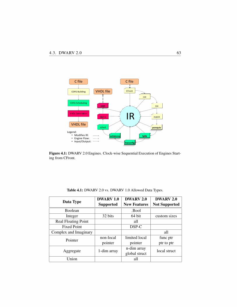
4.3. DWARV 2.0 63
psrequiv
IRemit
cse
CFront
fplib
match
ssa
hwconfig
setlatency
sched
dump
C file
VHDL file
Legend:• Modifies IR: • Engine Flow:• Input/Output:
C file
VHDL Generation
CDFG Scheduling
CDFG Building
VHDL file
Figure 4.1: DWARV 2.0 Engines. Clock-wise Sequential Execution of Engines Start-ing from CFront.
Table 4.1: DWARV 2.0 vs. DWARV 1.0 Allowed Data Types.
Data Type DWARV 1.0 DWARV 2.0 DWARV 2.0Supported New Features Not Supported
Boolean BoolInteger 32 bits 64 bit custom sizes
Real Floating Point allFixed Point DSP-C
Complex and Imaginary all
Pointernon-local limited local func ptrpointer pointer ptr to ptr
Aggregate 1-dim arrayn-dim array
local structglobal struct
Union all
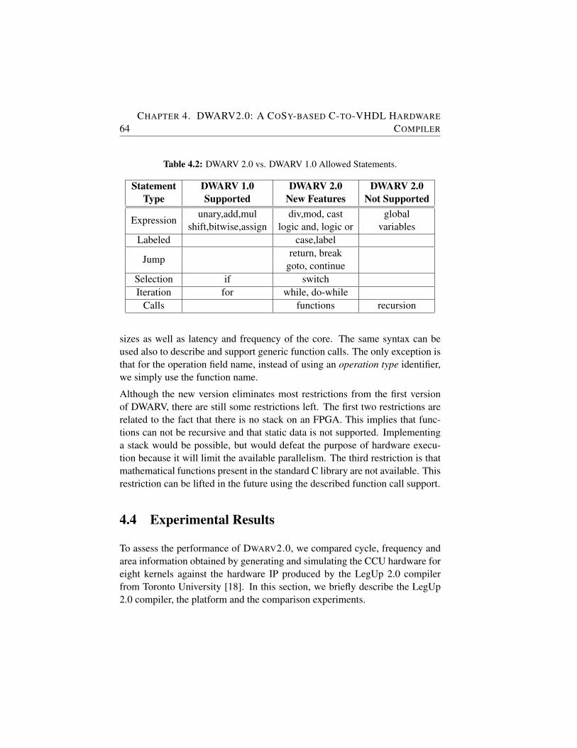
64CHAPTER 4. DWARV2.0: A COSY-BASED C-TO-VHDL HARDWARE
COMPILER
Table 4.2: DWARV 2.0 vs. DWARV 1.0 Allowed Statements.
Statement DWARV 1.0 DWARV 2.0 DWARV 2.0Type Supported New Features Not Supported
Expressionunary,add,mul div,mod, cast global
shift,bitwise,assign logic and, logic or variablesLabeled case,label
Jumpreturn, break
goto, continueSelection if switchIteration for while, do-while
Calls functions recursion
sizes as well as latency and frequency of the core. The same syntax can beused also to describe and support generic function calls. The only exception isthat for the operation field name, instead of using an operation type identifier,we simply use the function name.
Although the new version eliminates most restrictions from the first versionof DWARV, there are still some restrictions left. The first two restrictions arerelated to the fact that there is no stack on an FPGA. This implies that func-tions can not be recursive and that static data is not supported. Implementinga stack would be possible, but would defeat the purpose of hardware execu-tion because it will limit the available parallelism. The third restriction is thatmathematical functions present in the standard C library are not available. Thisrestriction can be lifted in the future using the described function call support.
4.4 Experimental Results
To assess the performance of DWARV2.0, we compared cycle, frequency andarea information obtained by generating and simulating the CCU hardware foreight kernels against the hardware IP produced by the LegUp 2.0 compilerfrom Toronto University [18]. In this section, we briefly describe the LegUp2.0 compiler, the platform and the comparison experiments.
4.4. EXPERIMENTAL RESULTS 65
LegUp 2.0 Compiler
LegUp 2.0 [18] is a research compiler developed at Toronto University whichwas developed using LLVM [66]. It accepts standard C-language as input,and generates Verilog code for the selected input functions. Its main strengthis that it can generate hardware for complete applications or only for specificapplication functions, i.e., accelerators. In this latter case, a TigerMIPS softprocessor [65] is then used to execute the remainder of the application in soft-ware. The connection between these two main components is made throughan Avalon system bus. This is similar to the Molen machine organization,therefore comparing the execution times of accelerators generated by this toolis relevant to assess the performance and development state of DWARV2.0.LegUp 2.0 was reported [18] to perform close to an industrial HLS compiler,i.e., eXCite [28], which, assuming transitivity of results, was another reason touse LegUp 2.0 as our benchmark.
Experimental Platform
To compare the DWARV2.0 and LegUp 2.0 compilers, we followed a two-step approach. First, we simulated the generated kernels to obtain the cycleinformation. The simulation infrastructure for DWARV2.0 is in such a waydesigned to return only the execution time for the individual kernel invocation.However, for the LegUp 2.0 simulation, care has to be taken to obtain onlythe execution time for the kernel itself and not for the complete testbench asit is currently reported when the hybrid execution is chosen. To obtain thecorrect number, the ModelSim wave-form had to be opened, and the differencebetween the start and finish signals had to be computed.
Subsequently, we ran a full post-place and route synthesis to obtain the maxi-mum frequency and area numbers for the Xilinx Virtex5 ML510 developmentboard. To obtain a meaningful comparison, we needed to integrate the LegUp2.0 generated kernels in the Molen workflow to target the same board. To thispurpose, we wrote wrappers around the LegUp 2.0 interface. Note that thesewrappers do not influence the performance comparison. We use these wrappersonly for integration purposes to be able to target a different platform than theone for which LegUp kernels were generated. Doing so, we are interested onlyin the area numbers obtained for Xilinx instead of Altera board. The perfor-mance numbers are computed thus in the original setting without any wrappersincluded. Given that the tools target similar heterogeneous platforms with theaccelerated kernels running on the Xilinx board as co-processors of the Pow-
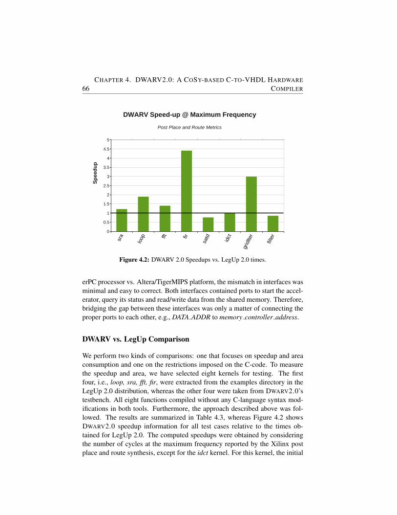
66CHAPTER 4. DWARV2.0: A COSY-BASED C-TO-VHDL HARDWARE
COMPILER
Speedup
Page 1
sra
loop fft fir
satd
idct
gridIter
filter
0
0.5
1
1.5
2
2.5
3
3.5
4
4.5
5
DWARV Speed-up @ Maximum Frequency
Post Place and Route Metrics
Sp
eed
up
Figure 4.2: DWARV 2.0 Speedups vs. LegUp 2.0 times.
erPC processor vs. Altera/TigerMIPS platform, the mismatch in interfaces wasminimal and easy to correct. Both interfaces contained ports to start the accel-erator, query its status and read/write data from the shared memory. Therefore,bridging the gap between these interfaces was only a matter of connecting theproper ports to each other, e.g., DATA ADDR to memory controller address.
DWARV vs. LegUp Comparison
We perform two kinds of comparisons: one that focuses on speedup and areaconsumption and one on the restrictions imposed on the C-code. To measurethe speedup and area, we have selected eight kernels for testing. The firstfour, i.e., loop, sra, fft, fir, were extracted from the examples directory in theLegUp 2.0 distribution, whereas the other four were taken from DWARV2.0’stestbench. All eight functions compiled without any C-language syntax mod-ifications in both tools. Furthermore, the approach described above was fol-lowed. The results are summarized in Table 4.3, whereas Figure 4.2 showsDWARV2.0 speedup information for all test cases relative to the times ob-tained for LegUp 2.0. The computed speedups were obtained by consideringthe number of cycles at the maximum frequency reported by the Xilinx postplace and route synthesis, except for the idct kernel. For this kernel, the initial
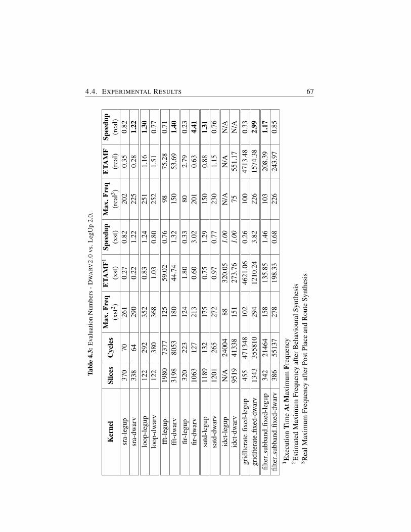
4.4. EXPERIMENTAL RESULTS 67Ta
ble
4.3:
Eva
luat
ion
Num
bers
-D
WA
RV
2.0
vs.L
egU
p2.
0.
Ker
nel
Slic
esC
ycle
sM
ax.F
req
ETA
MF1
Spee
dup
Max
.Fre
qE
TAM
FSp
eedu
p(x
st2 )
(xst
)(x
st)
(rea
l3 )(r
eal)
(rea
l)sr
a-le
gup
370
7026
10.
270.
8220
20.
350.
82sr
a-dw
arv
338
6429
00.
221.
2222
50.
281.
22lo
op-l
egup
122
292
352
0.83
1.24
251
1.16
1.30
loop
-dw
arv
122
380
368
1.03
0.80
252
1.51
0.77
fft-
legu
p19
8073
7712
559
.02
0.76
9875
.28
0.71
fft-
dwar
v31
9880
5318
044
.74
1.32
150
53.6
91.
40fir
-leg
up32
022
312
41.
800.
3380
2.79
0.23
fir-d
war
v10
6312
721
30.
603.
0220
10.
634.
41sa
td-l
egup
1189
132
175
0.75
1.29
150
0.88
1.31
satd
-dw
arv
1201
265
272
0.97
0.77
230
1.15
0.76
idct
-leg
upN
/A24
004
8832
0.05
1.00
N/A
N/A
N/A
idct
-dw
arv
9519
4133
815
127
3.76
1.00
7555
1.17
N/A
grid
Iter
ate
fixed
-leg
up45
547
1348
102
4621
.06
0.26
100
4713
.48
0.33
grid
Iter
ate
fixed
-dw
arv
1343
3558
1029
412
10.2
43.
8222
615
74.3
82.
99fil
ter
subb
and
fixed
-leg
up34
221
464
158
135.
851.
4610
320
8.39
1.17
filte
rsu
bban
dfix
ed-d
war
v38
655
137
278
198.
330.
6822
624
3.97
0.85
1E
xecu
tion
Tim
eA
tMax
imum
Freq
uenc
y2E
stim
ated
Max
imum
Freq
uenc
yaf
terB
ehav
iour
alSy
nthe
sis
3R
ealM
axim
umFr
eque
ncy
afte
rPos
tPla
cean
dR
oute
Synt
hesi
s
68CHAPTER 4. DWARV2.0: A COSY-BASED C-TO-VHDL HARDWARE
COMPILER
maximum frequency estimation was used. LegUp 2.0 idct kernel could not besynthesized targeting Xilinx because it contained an instantiation of an Alteraproprietary/specific IP block used for integer division. We compared the exe-cution times at the kernel level only which gives an indication of the quality ofthe generated HDL.
Analyzing the last column in Table 4.3, we observe that performance-wise,DWARV2.0 gave a speedup for four kernels, icdt provided no improvementor degradation (6th column), whereas the other three functions incurred a de-crease in performance. These speedup numbers were computed by first calcu-lating the Execution Time achieved At Maximum Frequency (ETAMF) re-ported for the two hardware versions, i.e., ETAMF = Cycles/Max .Freq..Next, Speedupdwarv = ETAMFlegup/ETAMFdwarv .
With respect to the hardware area, DWARV2.0 produces less than optimal hard-ware designs because no optimization passes that target area reduction wereused. Our primary focus was functional correctness and to obtain a basis forcomparison for future research. As an example of such future research, con-sider the loop kernel case study. Only by integrating the standard CoSy frame-work engines loopanalysis and loopunroll, which annotate respectively unrollsimple loops, we decreased the number of cycles for this kernel from 380 to113. Given the newly obtained frequency of 256 MHz, we were able to ob-tain a speedup of 1.90 for this example as well (initial numbers are given inTable 4.3 where we can see that the first implementation in DWARV2.0 gavea 0.77 slowdown). Figure 4.2 shows the final results obtained after this sim-ple optimization was applied. Even though the loopunroll engine can provideconsiderable performance benefits, determining an unroll factor is not a trivialproblem. If the unroll factor is too big, the generated VHDL will not synthe-size due to lack of available area. Chapter 6 will address this problem.
To gain more insight on how the two tools compare and decide if a tool is per-forming better than the other one, we illustrate in Figure 4.3 the performanceratios in terms of area ratios. This graph shows that for three kernels (i.e.,fir, griditerate and fft), DWARV2.0 generated designs perform better, but atthe cost of more hardware logic. This means that these points are not actuallycomparable because LegUp 2.0 generates more balanced area-performance de-signs, while for DWARV2.0 the focus is only on performance. filter, loop andsatd are kernels for which DWARV2.0 is slower than LegUp 2.0, given area isabout the same. Finally, sra is faster in DWARV2.0 under the same conditions.
The second comparison focused on the extent that the compilers are capableof compiling a large subset of the C-language without requiring substantial
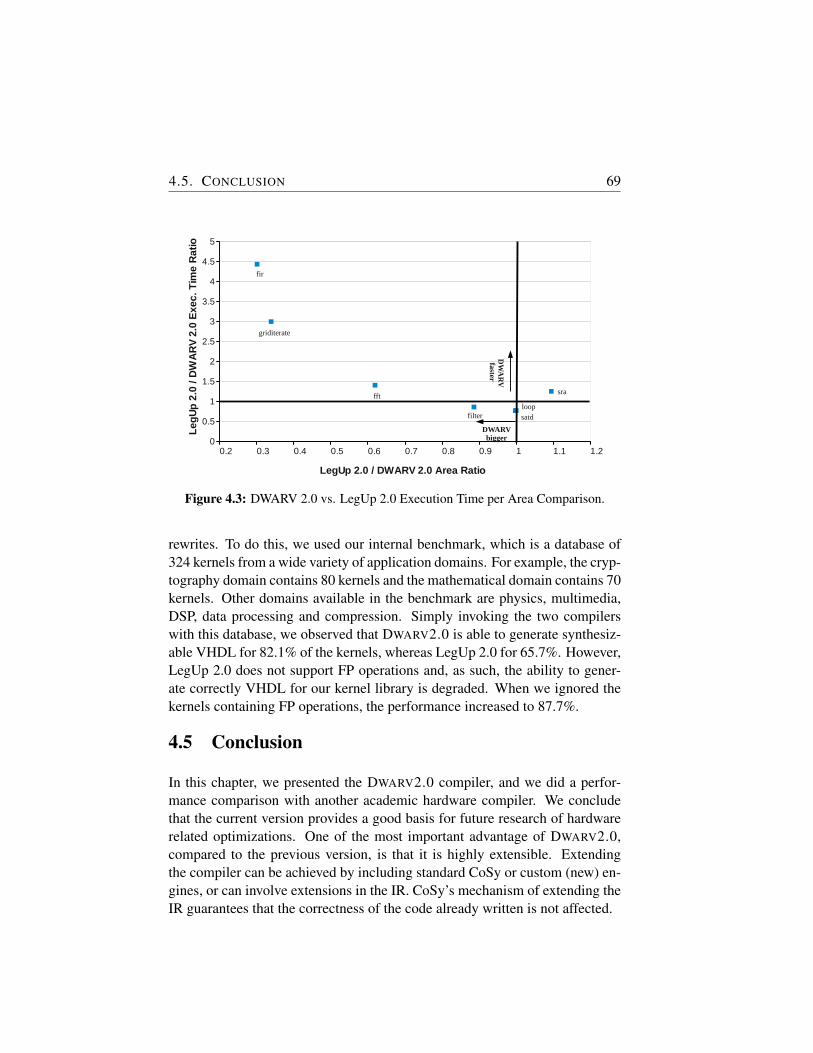
4.5. CONCLUSION 69
Sheet1
Page 1
0.2 0.3 0.4 0.5 0.6 0.7 0.8 0.9 1 1.1 1.20
0.5
1
1.5
2
2.5
3
3.5
4
4.5
5
LegUp 2.0 / DWARV 2.0 Area Ratio
Le
gU
p 2
.0 /
DW
AR
V 2
.0 E
xe
c.
Tim
e R
atio
DW
AR
V faster
DWARV bigger
sra
loopsatdfilter
fft
griditerate
fir
Figure 4.3: DWARV 2.0 vs. LegUp 2.0 Execution Time per Area Comparison.
rewrites. To do this, we used our internal benchmark, which is a database of324 kernels from a wide variety of application domains. For example, the cryp-tography domain contains 80 kernels and the mathematical domain contains 70kernels. Other domains available in the benchmark are physics, multimedia,DSP, data processing and compression. Simply invoking the two compilerswith this database, we observed that DWARV2.0 is able to generate synthesiz-able VHDL for 82.1% of the kernels, whereas LegUp 2.0 for 65.7%. However,LegUp 2.0 does not support FP operations and, as such, the ability to gener-ate correctly VHDL for our kernel library is degraded. When we ignored thekernels containing FP operations, the performance increased to 87.7%.
4.5 Conclusion
In this chapter, we presented the DWARV2.0 compiler, and we did a perfor-mance comparison with another academic hardware compiler. We concludethat the current version provides a good basis for future research of hardwarerelated optimizations. One of the most important advantage of DWARV2.0,compared to the previous version, is that it is highly extensible. Extendingthe compiler can be achieved by including standard CoSy or custom (new) en-gines, or can involve extensions in the IR. CoSy’s mechanism of extending theIR guarantees that the correctness of the code already written is not affected.
70CHAPTER 4. DWARV2.0: A COSY-BASED C-TO-VHDL HARDWARE
COMPILER
Note.
The content of this chapter is based on the following paper:
R. Nane, V.M. Sima, B. Olivier, R.J. Meeuws, Y.D. Yankova, K.L.M. Bertels,DWARV 2.0: A CoSy-based C-to-VHDL Hardware Compiler, 22nd In-ternational Conference on Field Programmable Logic and Applications (FPL2012), Oslo, Norway, September 2012.
5IP-XACT Extensions for Reconfigurable
Computing
MANY of today’s embedded multiprocessor systems are implementedas heterogeneous systems, consisting of hardware and softwarecomponents. To automate the composition and integration of mul-
tiprocessor systems, the IP-XACT standard was defined to describe hardwareIntellectual Property (IP) blocks and (sub)systems. However, the IP-XACTstandard does not provide sufficient means to express Reconfigurable Comput-ing (RC) specific information, such as Hardware-dependent Software (HdS)metadata, which prevents automated integration. In this chapter, we proposeseveral IP-XACT extensions such that the HdS can be generated and inte-grated automatically. We validate these specific extensions and demonstratethe interoperability of the approach based on an H.264 decoder applicationcase study. For this case study we achieved an overall 30.4% application-wisespeedup and we reduced the development time of HdS from days to a fewseconds.
5.1 Introduction
Heterogeneous systems combine different hardware cores (e.g., different pro-cessor types) to enable the execution of software on different pieces of hard-ware to increase performance. A trivial example is a general-purpose processortightly coupled with a co-processor to perform floating-point operations fast.Such a system can thus be used to off-load computational-intensive applicationcodes onto specialized hardware units. The objective is to gain performance.However, such a system is beneficial only in predefined scenarios. The sys-tem’s specialized hardware units are not useful for other software algorithms.
71
72CHAPTER 5. IP-XACT EXTENSIONS FOR RECONFIGURABLE
COMPUTING
To extend the range in which heterogeneous systems can be applied, reconfig-urable hardware devices were introduced. These have the advantage that thehardware design can be customized and configured on a per case basis.
A widely adopted practice within Reconfigurable Computing (RC) design isto accelerate part(s) of applications, using custom hardware architectures, thatare specifically tailored for a particular application. These specialized archi-tectures can be IP blocks written at the Register Transfer Level (RTL) by adesigner, or IP blocks generated by a High-Level Synthesis (HLS) tool from afunctional specification written in a High-Level Language (HLL) [97]. To copewith the diversity of IP blocks coming from different sources, IP-XACT [1]was introduced. Using IP-XACT, hardware components can be described ina standardized way. This enables automated configuration and integration ofIP blocks, aiding hardware reuse and facilitating tool interoperability [56].
In a Hardware/Software (HW/SW) system, connecting the different HW andSW components, using for instance buses or point-to-point connections, isnot sufficient to fully implement a system. Typically, a SW component con-nected to a HW component needs a driver program, also known as Hardware-dependent Software (HdS) [98], to control the HW component. IP blocks thatcan be controlled from a SW component are typically shipped with particu-lar HdS to ensure proper control from SW. However, in RC systems, the IPblocks are automatically generated by HW tool-chains for application kernelsselected for hardware acceleration. Therefore, the HdS driving these new hard-ware blocks has to be generated automatically as well. The compilation pro-cess in such RC systems, i.e., from HLL application source code to a combinedHW/SW executable, is done by different tools, such as partitioning, mappingand HW/SW generation tools. This implies that there is no central place fromwhere the HdS can be generated. That is, the compiler used to generate the IPhas no knowledge about what HW primitives are used for example to commu-nicate data in the system, which prevents it from generating a proper driver.This information is available, however, in the partitioning and mapping tool.Therefore, we adopt a layered solution in which different parts of the HdS aregenerated at different points in the tool-flow. Furthermore, to allow the toolsinvolved in this HdS generation process to communicate seamlessly with eachother, we need to describe the software requirements of each step in IP-XACTas well. One example of such a software requirement is the number of func-tion input parameters. However, unlike the RTL constituents of an IP block,which can be already described using the current IP-XACT standard, there isno standardized way to describe the driver information for an IP.
5.2. RELATED WORK 73
In this chapter, we elaborate on the expressiveness of IP-XACT for describingHdS metadata, addressing the second challenge of this dissertation. Further-more, we address the automation of HdS generation in the RC field, where IPsand their HdS are generated on the fly, and, therefore, are not fully predefined.The contribution of this chapter can be summarized as follows:
• We combine two proven technologies used in MPSoC design, namelyIP-XACT and HdS, to automatically integrate different architecturaltemplates used in RC systems.
• We investigate and propose IP-XACT extensions to allow automaticgeneration of HdS in RC tool-chains.
The rest of the chapter is organized as follows. Section 5.2 presents IP-XACT,other HdS solutions, and already proposed IP-XACT extensions. Section 5.3describes a HdS generation case study and investigates the IP-XACT sup-port for automation. Section 5.4 elaborates on the identified shortcomings andproposes IP-XACT extensions to support software related driver descriptions.Section 5.5 respectively Section 5.6 validates the automated integration andconcludes the chapter.
5.2 Related Work
The IP-XACT standard (IEEE 1685-2009) [1] describes an XML schema formetadata modeling IP blocks and (sub)systems. The metadata is used in thedevelopment, implementation, and verification of electronic systems. In thischapter, we focus on Component schema for associating HdS to HW IP blocksand we focus on Generator-Chain schema to express compiler specific require-ments. The current schema provides limited support for software descriptions.Namely, one can only attach software file-sets to a component and describethe function parameter’s high level types. However, it does not offer meansto assign semantics to the attached file-set and how it should be used duringintegration of a complete system. Furthermore, it lacks means to model toolchains in which complex software generators are to be integrated. In Section5.4, we propose solutions to these problems.
The OpenFPGA CoreLib [95] working group focused on examining the IP-XACT Schema and proposed extensions for facilitating core reuse into HLLs.Wirthlin et al. [4] used XML to describe common IP block elements and de-fined their own schema using IP-XACT syntax. They proposed a lightweight
74CHAPTER 5. IP-XACT EXTENSIONS FOR RECONFIGURABLE
COMPUTING
version intended for Reconfigurable Computing (RC) systems, such as inter-face specifications and capturing HLLs data types information.
Other IP-XACT related research is focusing on extending the schema to incor-porate semantic information about IP elements. Kruijtzer et al. [54], proposedadding context labels to provide additional meaning to IP-XACT components.They use this to assess the correctness of interconnections in the system. Striket al. [76] studied aspects regarding IP (re)configurability to reuse these after apartial change of some parameters. They underline that IP-XACT is missingexpression evaluation fields to support flagging illegal (sub)system composi-tion. However, all proposed extensions discussed so far in this section consideronly the HW IP block. As mentioned in Section 5.1, for systems involvingboth HW and SW, one also needs to describe the HdS belonging to the HW IPto enable automated integration of a system. Therefore, we propose softwarerelated extensions for IP-XACT.
5.3 Integrating Orthogonal Computation Models
To investigate the IP-XACT capabilities to model HW/SW co-design toolchains supporting HdS generation and tool interoperability, we used an H.264decoder application implemented on an Field-Programmable Gate Array(FPGA) as a case study. The goal is to integrate different tools and modelssuch that we can automatically generate application specific MPSoC imple-mentations of sequentially specified applications. To realize this, we use theDaedalus [64] system-level synthesis toolset to implement an MPSoC fromsequential C code. In particular, from the Daedalus tool set we use the PNcompiler [92] to partition a sequential application into Polyhedral ProcessNetworks (PPN) and ESPAM [42] to map the partitioned application onto anFPGA. Outside the Daedalus toolset, we use DWARV2.0 (see Chapter 4) to au-tomatically generate hardware IP blocks for performance critical parts of thesequential C code. We first describe the problems observed when integratingthe two tools in Section 5.3.1. Subsequently, we present our extended frame-work in Section 5.3.2.
5.3.1 IP Core Integration
In [90], the PICO compiler from Synfora Inc. [3] was incorporated in theDaedalus tool-flow. This approach was used to achieve higher performance forPPN implementations by replacing computational-intensive nodes with func-
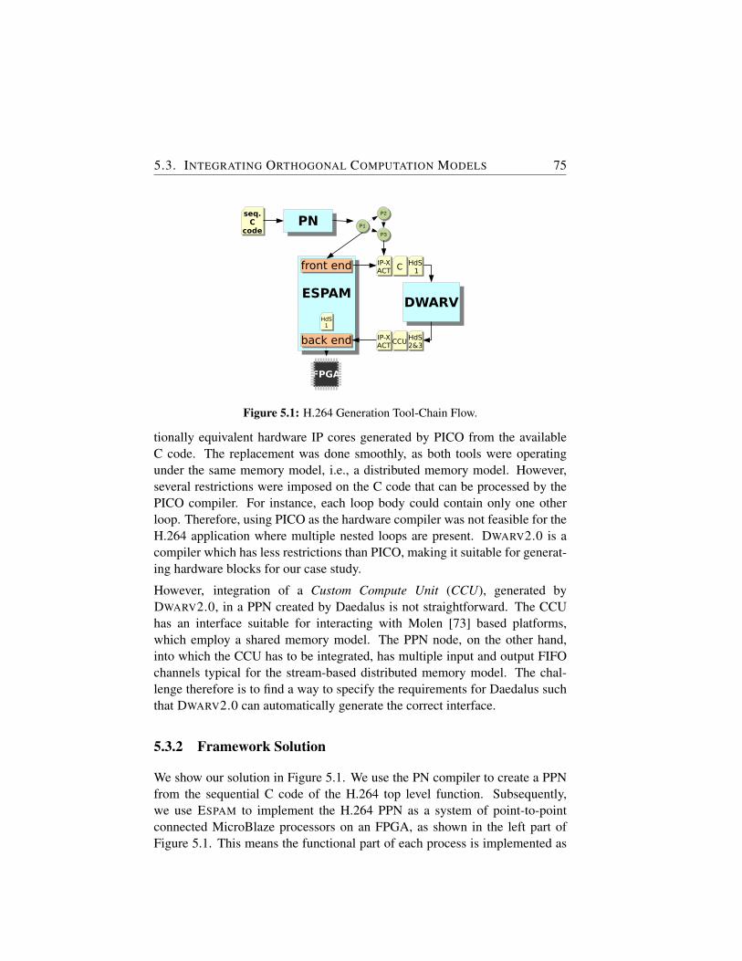
5.3. INTEGRATING ORTHOGONAL COMPUTATION MODELS 75
DWARVDWARV
P1P1
P2P2
P3P3
ESPAMESPAM
FPGA
back endback end
HdS 1
HdS 1
HdS2&3HdS2&3
IP-XACTIP-XACT
IP-XACTIP-XACT CC
CCUCCU
front endfront end
HdS1
HdS1
PNPNseq.C
code
seq.C
code
Figure 5.1: H.264 Generation Tool-Chain Flow.
tionally equivalent hardware IP cores generated by PICO from the availableC code. The replacement was done smoothly, as both tools were operatingunder the same memory model, i.e., a distributed memory model. However,several restrictions were imposed on the C code that can be processed by thePICO compiler. For instance, each loop body could contain only one otherloop. Therefore, using PICO as the hardware compiler was not feasible for theH.264 application where multiple nested loops are present. DWARV2.0 is acompiler which has less restrictions than PICO, making it suitable for generat-ing hardware blocks for our case study.
However, integration of a Custom Compute Unit (CCU), generated byDWARV2.0, in a PPN created by Daedalus is not straightforward. The CCUhas an interface suitable for interacting with Molen [73] based platforms,which employ a shared memory model. The PPN node, on the other hand,into which the CCU has to be integrated, has multiple input and output FIFOchannels typical for the stream-based distributed memory model. The chal-lenge therefore is to find a way to specify the requirements for Daedalus suchthat DWARV2.0 can automatically generate the correct interface.
5.3.2 Framework Solution
We show our solution in Figure 5.1. We use the PN compiler to create a PPNfrom the sequential C code of the H.264 top level function. Subsequently,we use ESPAM to implement the H.264 PPN as a system of point-to-pointconnected MicroBlaze processors on an FPGA, as shown in the left part ofFigure 5.1. This means the functional part of each process is implemented as
76CHAPTER 5. IP-XACT EXTENSIONS FOR RECONFIGURABLE
COMPUTING
a software program running on a MicroBlaze. Based on profile informationwe have decided to accelerate the Inverse Discrete Cosine Transform (IDCT)process using a specialized hardware component. We use the DWARV2.0 C-to-VHDL compiler to generate a CCU from the C code of the IDCT function,which requires the C function to be communicated from ESPAM to DWARV2.0.
To solve the interface mismatch problem between DWARV2.0-generatedCCUs and Daedalus’ PPNs, DWARV2.0 generates a wrapper for the CCU. Thiswrapper provides memory to the CCU which stores the input/output channeldata before/after the CCU is started/stopped.
The HdS controlling the CCU is structured into three different layers. The rightside of Figure 5.2 shows the HdS hierarchy. We distinguish platform prim-itives (layer 1), IP- and OS-specific driver code (layer 2) and an applicationlayer (layer 3). The primitives in layer 1 strongly depend on the processor theHdS is running on, and the way the CCU is connected to the processor runningthe HdS. For instance, for one processor these primitives use memory-mappedI/O, whereas for another processor dedicated instructions are available. Thisinformation is known only by ESPAM. Therefore, the HdS layer 1 primitivesare generated by ESPAM. HdS layer 2 provides functions that control the CCUby sending and receiving commands and data to and from the CCU using theprimitives provided by layer 1. The separation of HdS layers 1 and 2 makesthe HdS layer 2 code independent of the actual platform. HdS layer 3 pro-vides user level functions, which are invoked by a user application to performthe task for which the CCU was designed. The functions in layer 3 only usefunctions provided by HdS layer 2. The HdS layer 3 function(s) provide atransparent interface to the CCU, essentially making the CCU available as aregular software function.
5.4 IP-XACT Extensions
In this section, we elaborate on the expressiveness of the current IP-XACTstandard to describe the scenario presented in the previous section. Based onthis analysis, we describe three possible extensions, namely hardware compilerinput, HdS and tool-flow integration related extensions. We implemented theproposed extensions using the vendorExtensions extension construct that isalready part of IP-XACT. This allows vendor specific information to be addedto IP-XACT descriptions.
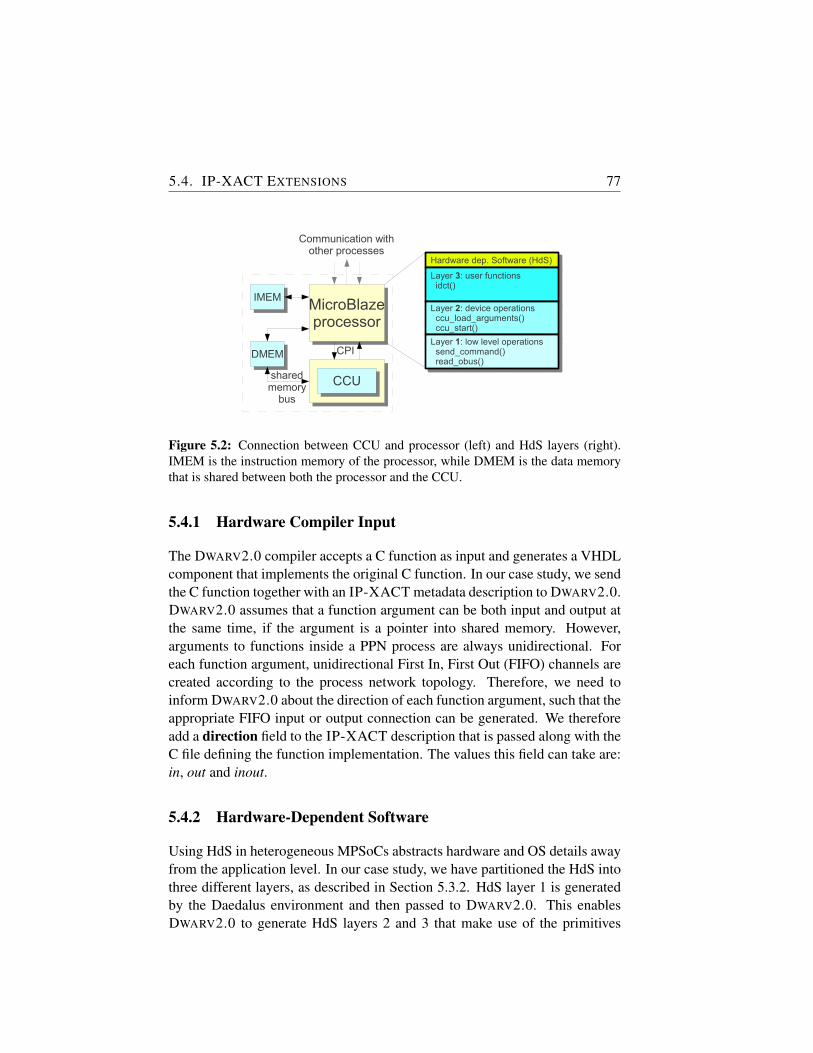
5.4. IP-XACT EXTENSIONS 77
CCUCCU
MicroBlazeprocessor
MicroBlazeprocessor
Communication withother processes
Hardware dep. Software (HdS)Hardware dep. Software (HdS)
Layer 3: user functions idct()
Layer 3: user functions idct()
Layer 2: device operations ccu_load_arguments() ccu_start()
Layer 2: device operations ccu_load_arguments() ccu_start()
Layer 1: low level operations send_command() read_obus()
Layer 1: low level operations send_command() read_obus()
IMEMIMEM
DMEMDMEM CPI
sharedmemory
bus
Figure 5.2: Connection between CCU and processor (left) and HdS layers (right).IMEM is the instruction memory of the processor, while DMEM is the data memorythat is shared between both the processor and the CCU.
5.4.1 Hardware Compiler Input
The DWARV2.0 compiler accepts a C function as input and generates a VHDLcomponent that implements the original C function. In our case study, we sendthe C function together with an IP-XACT metadata description to DWARV2.0.DWARV2.0 assumes that a function argument can be both input and output atthe same time, if the argument is a pointer into shared memory. However,arguments to functions inside a PPN process are always unidirectional. Foreach function argument, unidirectional First In, First Out (FIFO) channels arecreated according to the process network topology. Therefore, we need toinform DWARV2.0 about the direction of each function argument, such that theappropriate FIFO input or output connection can be generated. We thereforeadd a direction field to the IP-XACT description that is passed along with theC file defining the function implementation. The values this field can take are:in, out and inout.
5.4.2 Hardware-Dependent Software
Using HdS in heterogeneous MPSoCs abstracts hardware and OS details awayfrom the application level. In our case study, we have partitioned the HdS intothree different layers, as described in Section 5.3.2. HdS layer 1 is generatedby the Daedalus environment and then passed to DWARV2.0. This enablesDWARV2.0 to generate HdS layers 2 and 3 that make use of the primitives
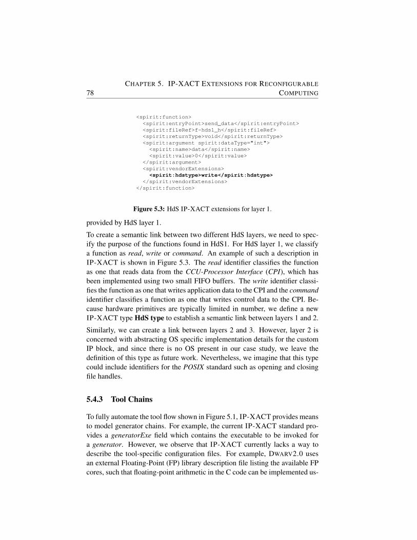
78CHAPTER 5. IP-XACT EXTENSIONS FOR RECONFIGURABLE
COMPUTING
<spirit:function><spirit:entryPoint>send_data</spirit:entryPoint><spirit:fileRef>f-hds1_h</spirit:fileRef><spirit:returnType>void</spirit:returnType><spirit:argument spirit:dataType="int"><spirit:name>data</spirit:name><spirit:value>0</spirit:value>
</spirit:argument><spirit:vendorExtensions><spirit:hdstype>write</spirit:hdstype>
</spirit:vendorExtensions></spirit:function>
Figure 5.3: HdS IP-XACT extensions for layer 1.
provided by HdS layer 1.
To create a semantic link between two different HdS layers, we need to spec-ify the purpose of the functions found in HdS1. For HdS layer 1, we classifya function as read, write or command. An example of such a description inIP-XACT is shown in Figure 5.3. The read identifier classifies the functionas one that reads data from the CCU-Processor Interface (CPI), which hasbeen implemented using two small FIFO buffers. The write identifier classi-fies the function as one that writes application data to the CPI and the commandidentifier classifies a function as one that writes control data to the CPI. Be-cause hardware primitives are typically limited in number, we define a newIP-XACT type HdS type to establish a semantic link between layers 1 and 2.
Similarly, we can create a link between layers 2 and 3. However, layer 2 isconcerned with abstracting OS specific implementation details for the customIP block, and since there is no OS present in our case study, we leave thedefinition of this type as future work. Nevertheless, we imagine that this typecould include identifiers for the POSIX standard such as opening and closingfile handles.
5.4.3 Tool Chains
To fully automate the tool flow shown in Figure 5.1, IP-XACT provides meansto model generator chains. For example, the current IP-XACT standard pro-vides a generatorExe field which contains the executable to be invoked fora generator. However, we observe that IP-XACT currently lacks a way todescribe the tool-specific configuration files. For example, DWARV2.0 usesan external Floating-Point (FP) library description file listing the available FPcores, such that floating-point arithmetic in the C code can be implemented us-
5.5. EXPERIMENTAL RESULTS 79
ing available FP cores. To allow seamless cooperation of different tools fromdifferent vendors, we observe the need to include tool-specific descriptions andfiles in IP-XACT generatorChain schema.
5.5 Experimental Results
In this section, we report on two kinds of results. First, we show the appli-cability and usefulness in a real world application and second, we report theoverall productivity gain. We base this on our experience with the H.264 casestudy, for which the first implementation was done manually.
5.5.1 Validation of Approach
In our experiments, we target a Xilinx Virtex-5 XC5VLX110T-2 FPGA anduse Xilinx EDK 9.2 for low-level synthesis. We use QCIF (176x144 pixels)video resolution and a 100 MHz clock frequency. To validate the approach,we implement the H.264 decoder application twice. The first time we map allprocesses of the PPN onto MicroBlaze processors, which means all PPN pro-cesses are implemented as software. This serves as our reference implemen-tation. The second time we replace the software IDCT node with a hardwareversion obtained using the methodology described in the previous sections. Weobtain a speedup of approximately 30.4%.
5.5.2 Productivity Gain
Besides proving the usefulness of the approach to obtain a faster implemen-tation of a PPN, we discuss the productivity gain observed when adoptingan automated IP-XACT based approach. If the automated support was notavailable, manually patching the tools would have been time consuming anderror-prone. Depending on the application knowledge of the system designerand application complexity, activities like writing the HdS or the CCU wrap-per can take from a few hours up to even weeks. Moreover, validation maytake a similar amount of time. For example, a memory map has to be specifiedas C code in the HdS and as VHDL in the RTL. For correct operation of thesystem, these two representations need to be fully consistent, which may be animportant source of errors when manual action is involved. We eliminate sucherrors by taking the information from a central source (e.g., an IP-XACT de-scription) and then automatically generate the different representations. This
80CHAPTER 5. IP-XACT EXTENSIONS FOR RECONFIGURABLE
COMPUTING
substantially reduces the time needed for validation. To fully understand thespecific challenges and properly design the modifications required by the toolsto enable automated integration, our first implementation of the system wasmanual. Based on this experience, we estimate that building a fully workingsystem for the H.264 decoder application by hand would take one week. Usingthe approach described in this work, one could obtain a working system in lessthan an hour, which is a considerable gain in productivity.
5.6 Conclusion
In this chapter, we have presented a new approach for automated generationof RTL implementations from sequential programs written in the C language.This is achieved by combining the Daedalus framework with the DWARV2.0C-to-VHDL compiler with the aid of the IP-XACT standard. With these con-cepts, even different architectural templates can be reconciled. We investigatedthe capabilities of the IP-XACT standard to model automated integration ofMPSoCs consisting of both hardware and software components. We found thatthe Hardware Dependent Software needed to control the hardware componentcannot be described in the current IP-XACT standard. We identified threepossible concepts that could be added as extensions to the IP-XACT standardto realize automated integration of HW/SW systems. Using an H.264 videodecoder application we validated our approach.
Note.
The content of this chapter is based on the following paper:
R. Nane, S. van Haastregt, T.P. Stefanov, B. Kienhuis, V.M. Sima, K.L.M. Ber-tels, IP-XACT Extensions for Reconfigurable Computing, 22nd IEEE Inter-national Conference on Application-specific Systems, Architectures and Pro-cessors (ASAP 2011), Santa Monica, USA, September 2011.
6Area Constraint Propagation in
High-Level Synthesis
HARDWARE compilers, which generate hardware descriptions fromhigh-level languages, are rapidly gaining in popularity. These gen-erated descriptions are used to obtain fast implementations of soft-
ware/hardware solutions in heterogeneous computing platforms. However, toobtain optimal solutions under certain platform constraints, we need intelligenthardware compilers that choose proper values for the different design parame-ters automatically. In this chapter, we present a two-step algorithm to optimizethe performance for different area constraints. The design parameters underinvestigation are the maximum unroll factor and the optimal allocation of re-source1 types. Experimental results show that generated solutions are mappedinto the available area at an occupancy rate between 74% and 99%. Further-more, these solutions provide the best execution time when compared to theother solutions that satisfy the same area constraint. Finally, a reduction in de-sign time of 42x on average can be achieved when these parameters are chosenby the compiler compared to manually selecting them.
6.1 Introduction
Heterogeneous multi-core architectures are a direct consequence of the end ofMoore’s law. In many cases, this heterogeneity is being implemented by meansof FPGA based custom computing units. The Xilinx Zynq at the embeddedside and the Convey HC-1 on the supercomputing side are just a couple of thetelling examples. The FPGA blades allow to provide application-specific hard-ware support, which can even be modified at run-time, and thus, provide a tai-
1resources and functional units are used interchangeably in the text
81
82CHAPTER 6. AREA CONSTRAINT PROPAGATION IN HIGH-LEVEL
SYNTHESIS
lored support for different application domains. The gain that can be obtainedby combining a traditional processor with a Reconfigurable Architecture (RA)can be tremendous (e.g., between 20x and 100x [40]). However, before thepotential of this technology can be fully exploited, a number of challengeshave to be addressed. One of the challenges is the automatic generation of thehardware units through e.g., C-to-VHDL generation, while a second importantchallenge is to have an efficient way to explore the design space. This chapterprimarily focuses on the second challenge.
The strength of RAs is that they offer much more design freedom than aGeneral-Purpose Processor (GPP). In this work, we rely on such architec-tures to maximize the application performance by automatically exploiting theavailable parallelism subject to area constraints. In particular, we look at appli-cation loops in more detail as these constructs provide a greater source of per-formance improvement, also in hardware synthesis. Considering the scenariowhere Hardware Description Language (HDL) code is automatically gener-ated, two important parameters have to be explored, namely, the degree ofparallelism (i.e., the loop unrolling factor) and the number of functional mod-ules used to implement the source High-Level Language (HLL) code. De-termining these parameters without any human intervention, is a key factorin building efficient HLL-to-HDL compilers and implicitly any Design SpaceExploration (DSE) tools.
This chapter presents an optimization algorithm to compute the above pa-rameters automatically. This optimization is added as an extension to theDWARV2.0 hardware compiler (see Chapter 4) which generates synthesizableVHDL on the basis of C-code. The contributions of this chapter are:
• The automatic determination of the maximum unroll factor to achievethe highest degree of parallelism subject to the available area and thefunction characteristics.
• The automatic computation of the number of functional units instanti-ated by the compiler, to optimize the performance given the previouslyidentified unroll factor and respecting the given design constraints.
• The validation of the algorithm through an implementation on an opera-tional platform.
The rest of the chapter is organized as follows. Section 6.2 presents the back-ground and related research. In Section 6.3 the details of the algorithm are
6.2. BACKGROUND AND RELATED WORK 83
presented while in Section 6.4 the experimental results are discussed. Finally,Section 6.5 draws the conclusions and highlights future research activities.
6.2 Background and Related Work
The MOLEN Machine Organization [73] is an architecture developed at TUDELFT that facilitates Hardware/Software (HW/SW) co-design. It includesthree main components, a GPP, Custom Computing Unit (CCU) used as anaccelerator and a shared memory between them. The CCUs are implementedon a reconfigurable (FPGA based) platform. In order to create an acceleratorfor this platform, we use DWARV2.0, a C-to-VHDL compiler, that generatesa CCU for an application kernel. More information about DWARV2.0 willbe given below. The generated CCU complies with a simple interface thatcontains ports to enable the exchange of data and control information. Thisallows changing the CCU while the system is running, without modifying thehardware design, thus allowing multiple applications and CCUs to execute atthe same time. Given enough resources, multiple CCUs can be executed inparallel, taking advantage of inherent application parallelism. To manage thereconfigurable area we divide it (logically) into slots, in which one CCU can bemapped. Each slot can be used by a different application. However, these slotscan be combined to allow different sized kernels to be mapped correspondingto different design goals. For example, possible layouts include 5 CCUs thateach use an equal area or 2 CCUs, having an area ratio of 3/2. Having onlyone slot using all the available area is another possible scenario.
DWARV2.0 (see Chapter 4) is a C-to-VHDL hardware compiler built withCoSy Compilers Framework [26]. Compilers built with CoSy are composedof a set of engines which work on the Intermediate Representation (IR) gener-ated based on the input program. The initial IR is generated by the frontend. Togenerate VHDL from C code, DWARV2.0 performs standard and custom trans-formations to the combined Control Data Flow Graph (CDFG). The ROCCCproject [48, 93] aims at the parallelization and acceleration of loops. Catapult-C [14] and CtoS [15] are commercial high-level synthesis tools that take asinput ANSI C/C++ and SystemC inputs and generate register transfer level(RTL) code. However, these compilers are complex and require extensive de-signer input in both the applied optimizations and the actual mapping process,making it less viable for a software designer that does not have in-depth hard-ware knowledge. Both Altium’s C to Hardware (CHC) [8] and LegUp [18]compilers are intended to compile annotated functions that belong to the ap-
84CHAPTER 6. AREA CONSTRAINT PROPAGATION IN HIGH-LEVEL
SYNTHESIS
plication’s computational intensive parts in a HW/SW co-design environment.
However, none of these compilers, including DWARV2.0, currently possesany capabilities to generate hardware that satisfies a particular area constraint,while maximizing performance. More precisely, requiring that a function’sgenerated HDL takes no more than a given area is not possible. Neither theunroll factor, nor the number of functional units used are determined takinginto account the execution time or the area. Performing this optimization auto-matically would enable high-level tool-chains to analyze different applicationmappings in a shorter amount of time. For example, the algorithm presentedin [74], where the best mapping of CCUs is selected given a fixed number ofresources and fixed kernel implementations, would be improved if the imple-mentations would be generated according to some determined area constraint.
6.3 Area Constrained Hardware Generation
In this section, we present the model that allows the compiler to decide theunroll factor and the number of resources. In the first part, we describe anddefine the problem while, in the second part, we elaborate on the details of thealgorithm. Finally, we conclude the section by showing how this model hasbeen integrated in the DWARV2.0 compiler.
6.3.1 Motivational Example and Problem Definition
To describe the problem, we make use of a synthetic case study. We con-sider a simple function that transforms each element of an input array basedon simple arithmetic operations with predefined weights (as in e.g., FIR fil-ter). The function has no loop-carried dependencies as each array element isprocessed independently of the others. Figure 6.1(b) shows this graphically,where Lb marks the beginning of the loop (i.e., compute the new value foreach of the array elements) and the number four in the superscript representsthe total number of loop iterations (i.e., we use an input array size of four ele-ments). The body of the loop is delimited by the rectangle box. The Le marksthe end of the four loop iterations. Furthermore, we see that, in this body, threeoperations are performed taking one cycle each for a total function executiontime of 12 cycle time (CT ). Unrolling once and given there are no loop-carrieddependencies, we can speedup the application by a factor of two if we woulddouble the resources. However, the overall speedup will depend on the avail-able hardware resources and is thus constrained by this. For instance, if we use
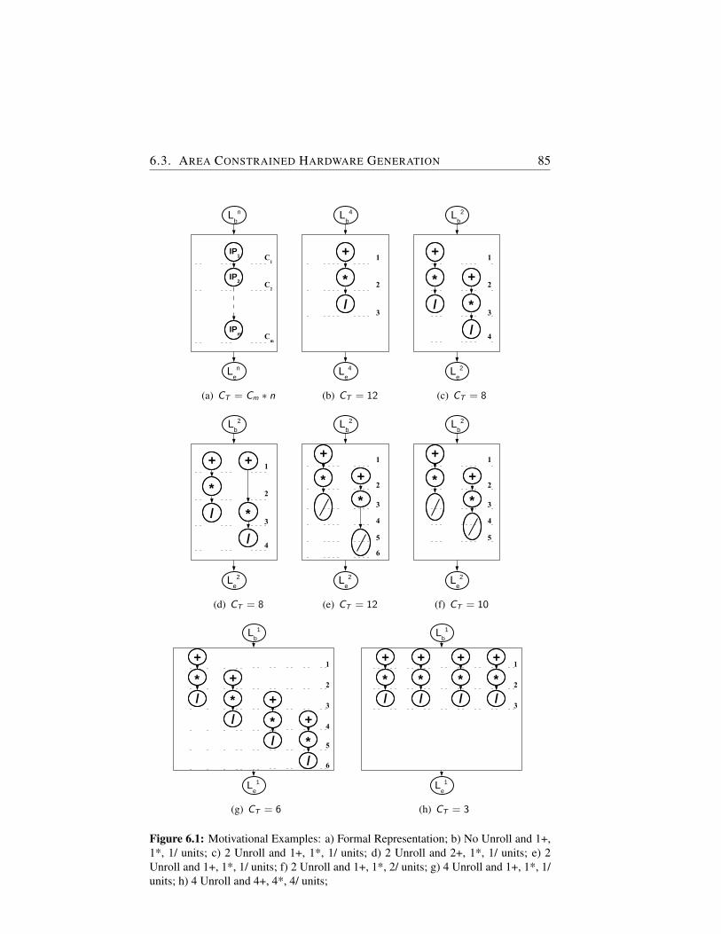
6.3. AREA CONSTRAINED HARDWARE GENERATION 85
Lb
n
Le
n
IP1
IPm C
m
IP2
C1
C2
(a) CT = Cm ∗ n
Lb
4
Le
4
+
3
*
1
2
/
(b) CT = 12
Lb
2
Le
2
+
3
*
1
2
/
+
*
/4
(c) CT = 8
Lb
2
Le
2
+
3
*
1
2
/
+
*
/4
(d) CT = 8
Lb
2
Le
2
+
3
*
1
2+
4
*
5
6
(e) CT = 12
Lb
2
Le
2
+
3
*
1
2+
4
*
5
(f) CT = 10
Lb
1
Le
1
3
1
2
4
5
6
+
*
/
+
*
/
+
*
/
+
*
/
(g) CT = 6
Lb
1
Le
1
3
1
2
+
*
/
+
*
/
+
*
/
+
*
/
(h) CT = 3
Figure 6.1: Motivational Examples: a) Formal Representation; b) No Unroll and 1+,1*, 1/ units; c) 2 Unroll and 1+, 1*, 1/ units; d) 2 Unroll and 2+, 1*, 1/ units; e) 2Unroll and 1+, 1*, 1/ units; f) 2 Unroll and 1+, 1*, 2/ units; g) 4 Unroll and 1+, 1*, 1/units; h) 4 Unroll and 4+, 4*, 4/ units;
86CHAPTER 6. AREA CONSTRAINT PROPAGATION IN HIGH-LEVEL
SYNTHESIS
only one resource of each type as in the initial case, the speedup would be lessthan the maximum possible (CT = 8 in Figure 6.1(c)).
Doubling only one resource type, as, for example, the addition unit (Figure6.1(d)), and keeping the initial assumption that each of the three computa-tions takes the same number of clock cycles (i.e., one clock cycle), does notdecrease the execution time while increasing the area. This is a suboptimalallocation of resources for the achieved execution time. It is important to notethat this scenario can falsely allow one to draw the conclusion that, for suchloop body types, the number of resources that should be used for each typeis the number corresponding to the resource with the minimum count in theloop. However, this is true only for the case where all resources compute theoutput in the same number of cycles. However, if this is not the case, whichis a fair assumption for real world applications, having different counts of re-sources is possible without obtaining a suboptimal resource allocation. Thisis illustrated in Figures 6.1(e) and 6.1(f). In the first illustration, we have thescenario when one resource of each type is used, while, in the second, only thenumber of division units is doubled. This leads to a decrease in CT from 12to 10 because the number of cycles for one loop iteration is decreased by onedue to the availability of a second division unit that can be used before the firstdivision finished execution.
Finally, fully unrolling the loop and using only one resource of each typeachieves a yet better execution time. This is illustrated in Figure 6.1(g) whereCT has been reduced to six cycles. Nevertheless, the best execution time (CT
= 3) is achieved when fully unrolling the loop and using the maximum possibleunits for each operation as shown in Figure 6.1(h). However, this can increasethe area past the available area for the function. This is specially important inour scenario, where the reconfigurable area is divided among differently sizedslots. For example, in the current implementation of the MOLEN machineorganization, we have available a maximum of five slots. Given run-time andpartial reconfigurability, the slots can be merged or split depending on the ap-plication’s requirements. This would lead to a different area requirement forone kernel. Therefore, it is necessary to have hardware compilers that auto-matically generate hardware designs that map onto the available area given asan input constraint. This would avoid iterating over the design choices to findthe optimal unroll factor and the maximum number of resources of each type,thus reducing the design space exploration time.
Summarizing, there is a trade-off between the number of unrolls one can doand the number of resources used for each unroll. The goal of our model is
6.3. AREA CONSTRAINED HARDWARE GENERATION 87
to compute the best combination given performance as the main design objec-tive. Given the general form of applications with loop body types as shown inFigure 6.1(a), we define the problem as follows: be the loop delimited by Ln
b
and Lne iterating n times, performing operations that use m different hardware
modules, IP1 to IPm, for which we know the sizes and latencies c1 to cm re-spectively, determine the unroll factor and the maximum number of modulesfor each of the m IP types such that the input area constraint is satisfied whilethe performance is maximized.
6.3.2 Optimization Algorithm
The algorithm consists of two parts, one for each parameter that needs to be de-termined. In the first step, we determine the unroll factor based on the availableFPGA area as well as the area increase due to wiring when more parallelism isavailable after an unroll is performed. Wiring is the total amount of hardwarelogic (i.e., wires) that is used for routing register and memory resources to cor-responding arithmetic unit(s) logic and vice-versa. To obtain the unroll factor(uf ) we solve inequality 6.1 for the maximum value of uf :
Ai + uf ∗ wi <= At (6.1)
,where Ai , At and wi represent the initial area of the kernel, the total areaavailable for the kernel on the target FPGA and the wiring increase per unroll,respectively. Furthermore, we have uf ∈ N and have obtained both Ai and wiafter a complete behavioral synthesis and estimation of the kernel’s generatedHDL. The initial kernel refers to the code ’just as is’, i.e., the code without anyunroll optimization applied and using the minimum number of resources foreach of the required IPs necessary to implement its functionality. The compileris executed once without activating any specific optimization regarding thenumber of IPs and unroll. The compiler is executed a second time with theloop unrolled once. Then, the wi is the difference between the estimated areaof these two generated kernels. The estimation is based on [59].
In the second step, we determine the necessary component counts to fit thehardware design onto the FPGA area available. This step assumes the IP sizesare available and can be loaded from an external library. However, if theseare not available, the netlist of the IP should be synthesized for the specificdevice, and the number of slices required for it should be saved in the externaldatabase. Furthermore, the available parallelism for each IP has been fixedby the previous step which unrolled the loop body. That means that no more
88CHAPTER 6. AREA CONSTRAINT PROPAGATION IN HIGH-LEVEL
SYNTHESIS
than some value n of IPs of type m (conditions 6.5 and 6.6 below) can executein parallel (inequality 6.4). The second constraint according to the problemdefinition involves the area of the IPs itself, which leads to the constraint thatthe sum of all IP sizes multiplied by the number of their instantiations shouldnot exceed the total area given as a parameter (inequality 6.3). Finally, theobjective is to minimize the time it takes to compute each level in the graphby instantiating as many resources of that type possible (6.2). The solution ofthe algorithm is obtained by selecting the maximum between these minimumschosen for each level in the CDFG. Note that minimizing the number of cyclesonly for a level in the CDFG is ineffective if the other levels with differentoperations are not minimized, as well. The complete set of (in)equations isshown below:
min : MAX{countIPi/xi + countIPi%xi?1 : 0} (6.2)m∑i=1
xi ∗ area{IPi} <= At (6.3)
xi <= tIPi∗ uf (6.4)
countIPi = MAX{tIPi∗ uf } (6.5)
xi ∈ N,∀i ∈ {1, ...,m} (6.6)
,where area is the area of the component accounting for both the number ofslices and on board Digital Signal Processor (DSP)s cores it requires. xi s arethe variables which represent how many IPs of type i can be used inside thetotal area available (At). Furthermore, tIPi
represents how many instances oftype IPi are used in the initial version of the code when no unroll has beenperformed.
6.3.3 Integration in DWARV2.0
The algorithm is shown in Figure 6.2 and includes two function calls corre-sponding to the above two steps described. In determineUnrollFactor(), wefirst load the necessary parameters to solve inequality 6.1. These are obtainedby (pre)compiling the kernel and using any estimation tool (such as Quipu [60]from the Delft Workbench tool-chain) on the generated HDL to predict the ini-tial area. Therefore, the result of the estimation is used to extract and storethe parameters required for the algorithm. These are fed into the compiler inthe second run for the same kernel. Figure 6.3 shows how the compiler flow
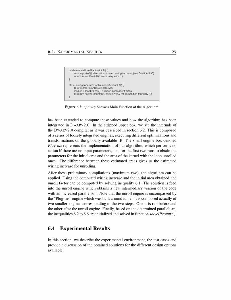
6.4. EXPERIMENTAL RESULTS 89
int determineUnrollFactor(int At) {wi = importWI(); //import estimated wiring increase (see Section III.C)return solveUF(wi,At)// solve inequality (1);
}
struct areagenparams optimizeForArea(int At) {I) uf = determineUnrollFactor(At);ipsizes = loadIPsizes(); // import component sizes II) return solveIPcounts(uf,ipsizes,At); // return solution found by (2)
}
Figure 6.2: optimizeForArea Main Function of the Algorithm.
has been extended to compute these values and how the algorithm has beenintegrated in DWARV2.0. In the stripped upper box, we see the internals ofthe DWARV2.0 compiler as it was described in section 6.2. This is composedof a series of loosely integrated engines, executing different optimizations andtransformations on the globally available IR. The small engine box denotedPlug-ins represents the implementation of our algorithm, which performs noaction if there are no input parameters, i.e., for the first two runs to obtain theparameters for the initial area and the area of the kernel with the loop unrolledonce. The difference between these estimated areas gives us the estimatedwiring increase for unrolling.
After these preliminary compilations (maximum two), the algorithm can beapplied. Using the computed wiring increase and the initial area obtained, theunroll factor can be computed by solving inequality 6.1. The solution is feedinto the unroll engine which obtains a new intermediary version of the codewith an increased parallelism. Note that the unroll engine is encompassed bythe ”Plug-ins” engine which was built around it, i.e., it is composed actually oftwo smaller engines corresponding to the two steps. One it is run before andthe other after the unroll engine. Finally, based on the determined parallelism,the inequalities 6.2 to 6.6 are initialized and solved in function solveIPcounts().
6.4 Experimental Results
In this section, we describe the experimental environment, the test cases andprovide a discussion of the obtained solutions for the different design optionsavailable.
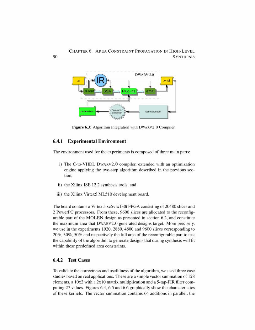
90CHAPTER 6. AREA CONSTRAINT PROPAGATION IN HIGH-LEVEL
SYNTHESIS
CFrontCFront
.c.c IRIRSSASSA Plug-insPlug-ins emitemit
.vhdl.vhdl
parametersparameters Estimation toolEstimation tool
DWARV 2.0
Parameterextraction
Parameterextraction
TODO: maybe add DataBase from where target-specific IP sizes are loaded!???
Figure 6.3: Algorithm Integration with DWARV2.0 Compiler.
6.4.1 Experimental Environment
The environment used for the experiments is composed of three main parts:
i) The C-to-VHDL DWARV2.0 compiler, extended with an optimizationengine applying the two-step algorithm described in the previous sec-tion,
ii) the Xilinx ISE 12.2 synthesis tools, and
iii) the Xilinx Virtex5 ML510 development board.
The board contains a Virtex 5 xc5vfx130t FPGA consisting of 20480 slices and2 PowerPC processors. From these, 9600 slices are allocated to the reconfig-urable part of the MOLEN design as presented in section 6.2, and constitutethe maximum area that DWARV2.0 generated designs target. More precisely,we use in the experiments 1920, 2880, 4800 and 9600 slices corresponding to20%, 30%, 50% and respectively the full area of the reconfigurable part to testthe capability of the algorithm to generate designs that during synthesis will fitwithin these predefined area constraints.
6.4.2 Test Cases
To validate the correctness and usefulness of the algorithm, we used three casestudies based on real applications. These are a simple vector summation of 128elements, a 10x2 with a 2x10 matrix multiplication and a 5-tap-FIR filter com-puting 27 values. Figures 6.4, 6.5 and 6.6 graphically show the characteristicsof these kernels. The vector summation contains 64 additions in parallel, the
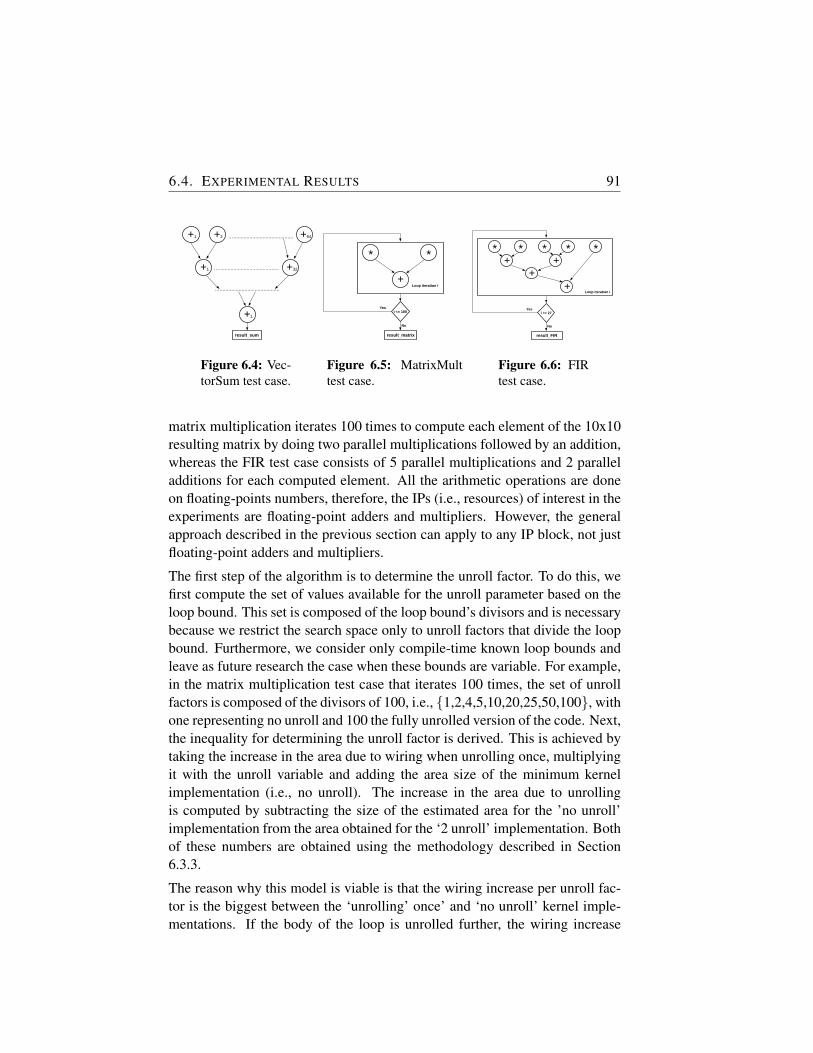
6.4. EXPERIMENTAL RESULTS 91
+1 +2 +64
+1
+1
….........................................
+32….........................................
….........................................
result_sum
Figure 6.4: Vec-torSum test case.
result_matrix
i <= 100
No
Yes
+
*
Loop iteration i
*
Figure 6.5: MatrixMulttest case.
result_FIR
i <= 27
No
Yes
Loop iteration i
*+* * * *
++
+
Figure 6.6: FIRtest case.
matrix multiplication iterates 100 times to compute each element of the 10x10resulting matrix by doing two parallel multiplications followed by an addition,whereas the FIR test case consists of 5 parallel multiplications and 2 paralleladditions for each computed element. All the arithmetic operations are doneon floating-points numbers, therefore, the IPs (i.e., resources) of interest in theexperiments are floating-point adders and multipliers. However, the generalapproach described in the previous section can apply to any IP block, not justfloating-point adders and multipliers.
The first step of the algorithm is to determine the unroll factor. To do this, wefirst compute the set of values available for the unroll parameter based on theloop bound. This set is composed of the loop bound’s divisors and is necessarybecause we restrict the search space only to unroll factors that divide the loopbound. Furthermore, we consider only compile-time known loop bounds andleave as future research the case when these bounds are variable. For example,in the matrix multiplication test case that iterates 100 times, the set of unrollfactors is composed of the divisors of 100, i.e., {1,2,4,5,10,20,25,50,100}, withone representing no unroll and 100 the fully unrolled version of the code. Next,the inequality for determining the unroll factor is derived. This is achieved bytaking the increase in the area due to wiring when unrolling once, multiplyingit with the unroll variable and adding the area size of the minimum kernelimplementation (i.e., no unroll). The increase in the area due to unrollingis computed by subtracting the size of the estimated area for the ’no unroll’implementation from the area obtained for the ‘2 unroll’ implementation. Bothof these numbers are obtained using the methodology described in Section6.3.3.
The reason why this model is viable is that the wiring increase per unroll fac-tor is the biggest between the ‘unrolling’ once’ and ‘no unroll’ kernel imple-mentations. If the body of the loop is unrolled further, the wiring increase
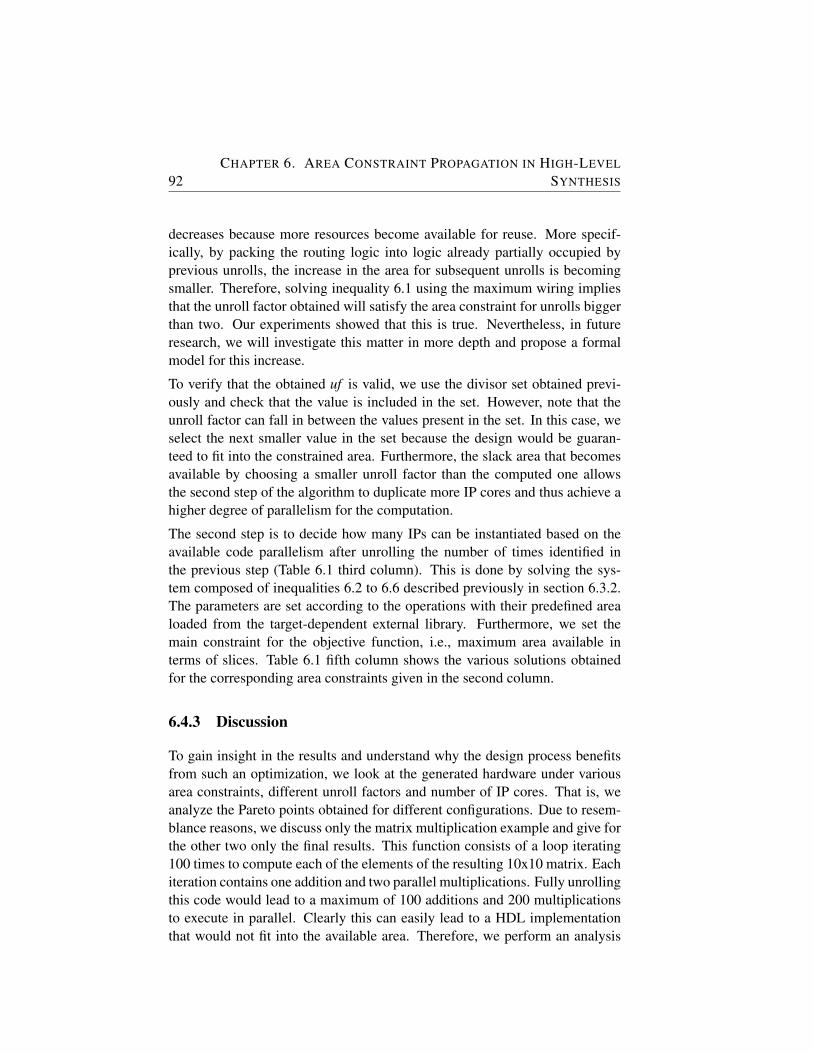
92CHAPTER 6. AREA CONSTRAINT PROPAGATION IN HIGH-LEVEL
SYNTHESIS
decreases because more resources become available for reuse. More specif-ically, by packing the routing logic into logic already partially occupied byprevious unrolls, the increase in the area for subsequent unrolls is becomingsmaller. Therefore, solving inequality 6.1 using the maximum wiring impliesthat the unroll factor obtained will satisfy the area constraint for unrolls biggerthan two. Our experiments showed that this is true. Nevertheless, in futureresearch, we will investigate this matter in more depth and propose a formalmodel for this increase.
To verify that the obtained uf is valid, we use the divisor set obtained previ-ously and check that the value is included in the set. However, note that theunroll factor can fall in between the values present in the set. In this case, weselect the next smaller value in the set because the design would be guaran-teed to fit into the constrained area. Furthermore, the slack area that becomesavailable by choosing a smaller unroll factor than the computed one allowsthe second step of the algorithm to duplicate more IP cores and thus achieve ahigher degree of parallelism for the computation.
The second step is to decide how many IPs can be instantiated based on theavailable code parallelism after unrolling the number of times identified inthe previous step (Table 6.1 third column). This is done by solving the sys-tem composed of inequalities 6.2 to 6.6 described previously in section 6.3.2.The parameters are set according to the operations with their predefined arealoaded from the target-dependent external library. Furthermore, we set themain constraint for the objective function, i.e., maximum area available interms of slices. Table 6.1 fifth column shows the various solutions obtainedfor the corresponding area constraints given in the second column.
6.4.3 Discussion
To gain insight in the results and understand why the design process benefitsfrom such an optimization, we look at the generated hardware under variousarea constraints, different unroll factors and number of IP cores. That is, weanalyze the Pareto points obtained for different configurations. Due to resem-blance reasons, we discuss only the matrix multiplication example and give forthe other two only the final results. This function consists of a loop iterating100 times to compute each of the elements of the resulting 10x10 matrix. Eachiteration contains one addition and two parallel multiplications. Fully unrollingthis code would lead to a maximum of 100 additions and 200 multiplicationsto execute in parallel. Clearly this can easily lead to a HDL implementationthat would not fit into the available area. Therefore, we perform an analysis
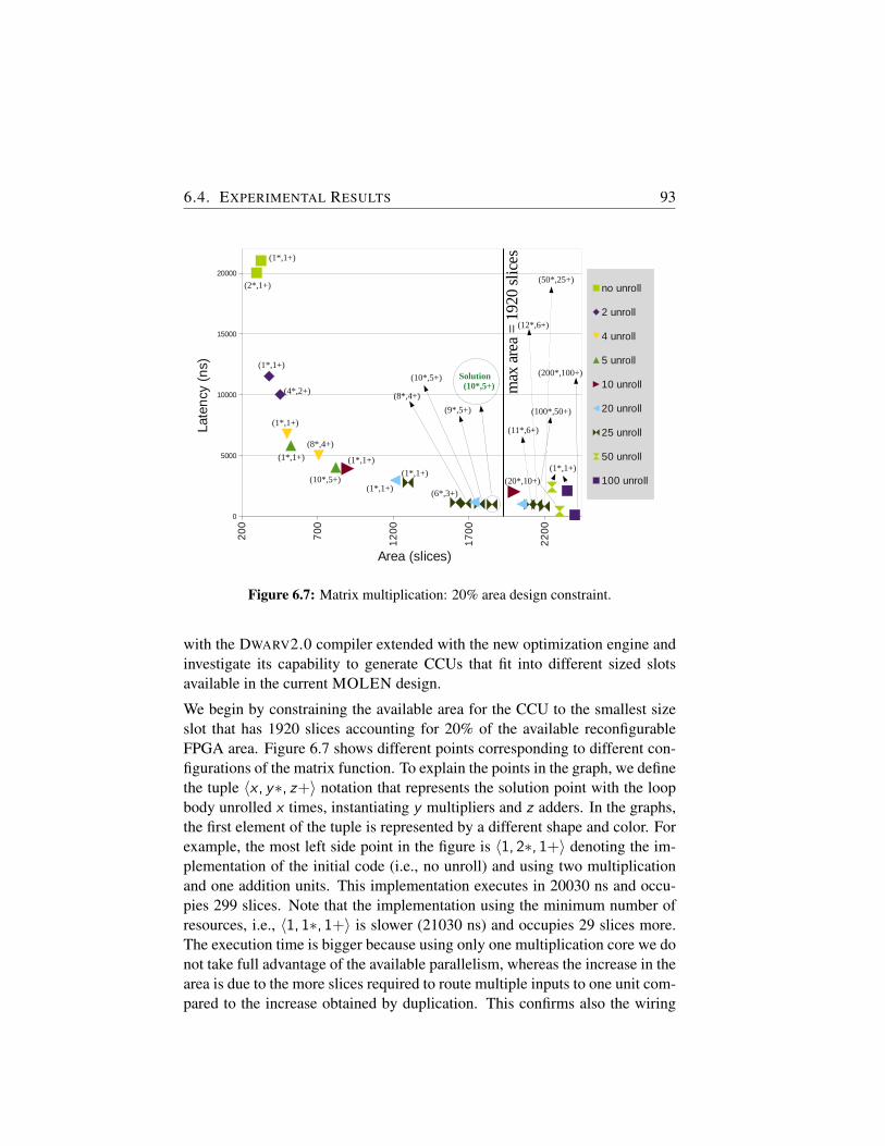
6.4. EXPERIMENTAL RESULTS 93
m_20
Page 1
name area
no unroll 299 20030 27315328 21030 28315
2 unroll 381 11530 18815454 10030 17315
4 unroll 500 6780 14065709 5030 12315
5 unroll 525 5830 13115822 4030 11315
10 unroll 900 3930 112152000 2030 9315
20 unroll 1213 2980 1026520unroll_10MUL_5ADD 1736 1180 8465
2050 1030 831525 unroll
1299 2790 100756MUL_3ADD 1612 1150 84358MUL_4ADD 1680 1070 83559MUL_5ADD 1771 1030 8315
10MUL_5ADD_SOL 1854 990 827511MUL_6ADD 2100 990 827512MUL_6ADD 2150 990 8275
2200 830 811550 unroll
2250 2410 96952300 430 7715
100 unroll 2350 2120 94052400 130 7415
nounroll_lim
2unroll_unlim
4unroll_unlim
5unroll_unlim
10unroll_unlim
20unroll_unlim
lim
unlim
limunlim
limunlim
20
0
70
0
12
00
17
00
22
00
0
5000
10000
15000
20000
no unroll
2 unroll
4 unroll
5 unroll
10 unroll
20 unroll
25 unroll
50 unroll
100 unroll
Area (slices)
Late
ncy
(n
s)
max
are
a =
1920
slic
es(1*,1+)
(2*,1+)
(1*,1+)
(4*,2+)
Solution (10*,5+)
(20*,10+)
(1*,1+)
(1*,1+)
(10*,5+)
(8*,4+)
(1*,1+)
(200*,100+)
(100*,50+)
(8*,4+)
(11*,6+)
(9*,5+)
(10*,5+)
(50*,25+)
(12*,6+)
(1*,1+)(1*,1+)
(1*,1+)(6*,3+)
Figure 6.7: Matrix multiplication: 20% area design constraint.
with the DWARV2.0 compiler extended with the new optimization engine andinvestigate its capability to generate CCUs that fit into different sized slotsavailable in the current MOLEN design.
We begin by constraining the available area for the CCU to the smallest sizeslot that has 1920 slices accounting for 20% of the available reconfigurableFPGA area. Figure 6.7 shows different points corresponding to different con-figurations of the matrix function. To explain the points in the graph, we definethe tuple 〈x , y∗, z+〉 notation that represents the solution point with the loopbody unrolled x times, instantiating y multipliers and z adders. In the graphs,the first element of the tuple is represented by a different shape and color. Forexample, the most left side point in the figure is 〈1, 2∗, 1+〉 denoting the im-plementation of the initial code (i.e., no unroll) and using two multiplicationand one addition units. This implementation executes in 20030 ns and occu-pies 299 slices. Note that the implementation using the minimum number ofresources, i.e., 〈1, 1∗, 1+〉 is slower (21030 ns) and occupies 29 slices more.The execution time is bigger because using only one multiplication core we donot take full advantage of the available parallelism, whereas the increase in thearea is due to the more slices required to route multiple inputs to one unit com-pared to the increase obtained by duplication. This confirms also the wiring
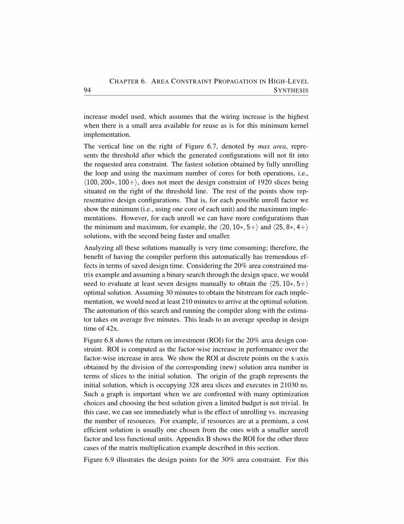
94CHAPTER 6. AREA CONSTRAINT PROPAGATION IN HIGH-LEVEL
SYNTHESIS
increase model used, which assumes that the wiring increase is the highestwhen there is a small area available for reuse as is for this minimum kernelimplementation.
The vertical line on the right of Figure 6.7, denoted by max area, repre-sents the threshold after which the generated configurations will not fit intothe requested area constraint. The fastest solution obtained by fully unrollingthe loop and using the maximum number of cores for both operations, i.e.,〈100, 200∗, 100+〉, does not meet the design constraint of 1920 slices beingsituated on the right of the threshold line. The rest of the points show rep-resentative design configurations. That is, for each possible unroll factor weshow the minimum (i.e., using one core of each unit) and the maximum imple-mentations. However, for each unroll we can have more configurations thanthe minimum and maximum, for example, the 〈20, 10∗, 5+〉 and 〈25, 8∗, 4+〉solutions, with the second being faster and smaller.
Analyzing all these solutions manually is very time consuming; therefore, thebenefit of having the compiler perform this automatically has tremendous ef-fects in terms of saved design time. Considering the 20% area constrained ma-trix example and assuming a binary search through the design space, we wouldneed to evaluate at least seven designs manually to obtain the 〈25, 10∗, 5+〉optimal solution. Assuming 30 minutes to obtain the bitstream for each imple-mentation, we would need at least 210 minutes to arrive at the optimal solution.The automation of this search and running the compiler along with the estima-tor takes on average five minutes. This leads to an average speedup in designtime of 42x.
Figure 6.8 shows the return on investment (ROI) for the 20% area design con-straint. ROI is computed as the factor-wise increase in performance over thefactor-wise increase in area. We show the ROI at discrete points on the x-axisobtained by the division of the corresponding (new) solution area number interms of slices to the initial solution. The origin of the graph represents theinitial solution, which is occupying 328 area slices and executes in 21030 ns.Such a graph is important when we are confronted with many optimizationchoices and choosing the best solution given a limited budget is not trivial. Inthis case, we can see immediately what is the effect of unrolling vs. increasingthe number of resources. For example, if resources are at a premium, a costefficient solution is usually one chosen from the ones with a smaller unrollfactor and less functional units. Appendix B shows the ROI for the other threecases of the matrix multiplication example described in this section.
Figure 6.9 illustrates the design points for the 30% area constraint. For this
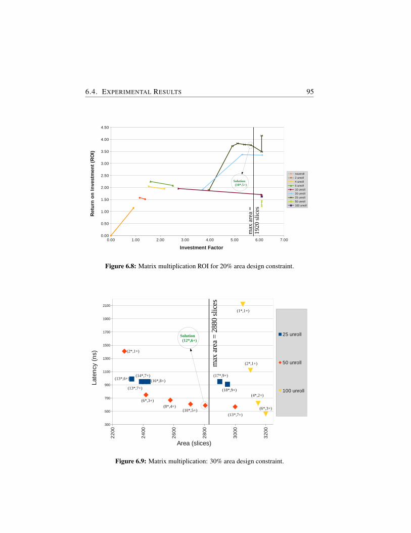
6.4. EXPERIMENTAL RESULTS 95
m_20
Page 1
name area X investment X gain ROI MAX area increase 7285328 21030 28315 0.00 0.00 0.00 5.85299 20030 27315 0.91 1.05 1.15
2 unroll 381 11530 18815 1.16 1.82 1.57454 10030 17315 1.38 2.10 1.51 NOTE: this graph I did not make it final! Because we can have different types of graphs
4 unroll 500 6780 14065 1.52 3.10 2.03709 5030 12315 2.16 4.18 1.93
5 unroll 525 5830 13115 1.60 3.61 2.25822 4030 11315 2.51 5.22 2.08
10 unroll 900 3930 11215 2.74 5.35 1.952000 2030 9315 6.10 10.36 1.70
20 unroll 1213 2980 10265 3.70 7.06 1.9120unroll_10MUL_5ADD 1736 1180 8465 5.29 17.82 3.37
2000 1030 8315 6.10 20.42 3.3525 unroll
1299 2790 10075 3.96 7.54 1.906MUL_3ADD 1612 1150 8435 4.91 18.29 3.728MUL_4ADD 1680 1070 8355 5.12 19.65 3.849MUL_5ADD 1771 1030 8315 5.40 20.42 3.78
10MUL_5ADD_SOL 1854 990 8275 5.65 21.24 3.7611MUL_6ADD 2000 990 8275 6.10 21.24 3.4812MUL_6ADD 2000 990 8275 6.10 21.24 3.48
2000 830 8115 6.10 25.34 4.1650 unroll
2000 2410 9695 6.10 8.73 1.432000 430 7715 6.10 7.54 1.24
100 unroll 2000 2120 9405 6.10 9.92 1.632000 130 7415 6.10 9.92 1.63
exec.time without memtransferexec.time with mem transfernounroll
no unroll_unlim
2unroll_unlimwhat I can do here is to show for how much increase in area (until 100% procent) the evolution of performance
4unroll_unlim
5unroll_unlim
10unroll_unlim
20unroll_unlim
lim
unlim
limunlim
limunlim
0.00 1.00 2.00 3.00 4.00 5.00 6.00 7.000.00
0.50
1.00
1.50
2.00
2.50
3.00
3.50
4.00
4.50
nounroll
2 unroll
4 unroll
5 unroll
10 unroll
20 unroll
25 unroll
50 unroll
100 unroll
Investment Factor
Ret
urn
on
In
vest
men
t (R
OI)
max
are
a =
19
20 s
lice
s
Solution (10*,5+)
Figure 6.8: Matrix multiplication ROI for 20% area design constraint.
m_30
Page 1
name area25 unroll
13MUL_6ADD 2325 80 38 990 8275 13*,6+ 50*, 25+13MUL_7ADD_SOL 2432 84 40 950 8235 13*,7+ 50*, 25+
14MUL_7ADD 2407 83 42 950 8235 14*,7+ 50*, 25+15MUL_7ADD 2900 N/A ERROR: unplaced 22 FF950 8235 15*,7+ 50*, 25+16MUL_8ADD 2388 82 48 950 8235 16*,8+ 50*, 25+17MUL_9ADD 2950 N/A ERROR: !DSP (52>48)910 8195 17*,9+ 50*, 25+
50 unroll #VALUE! 2MUL_1ADD 2277 79 6 1410 8695 2*,1+ 100*, 50+4MUL_2ADD 2327 80 12 910 8195 4*,2+ 100*, 50+6MUL_3ADD 2418 83 18 750 8035 6*,3+ 100*, 50+8MUL_4ADD 2577 89 24 670 7955 8*,4+ 100*, 50+
10MUL_5ADD 2709 94 30 610 7895 10*, 5+ 100*, 50+12MUL_6ADD 2805 97 36 590 7875 12*,6+ 100*, 50+
13MUL_7ADD_SOL 3000 N/A ERROR: !sites 570 7855 13*,7+ 100*, 50+100 unroll #VALUE!
3050 N/A ERROR: FF 15450 > 115202120 9405 1*,1+ 200*,100+2MUL_1ADD 3100 N/A ERROR: FF 15452 > 115201120 8405 2*,1+ 200*,100+4MUL_2ADD 3150 N/A ERROR: FF 15896 > 11520620 7905 4*,2+ 200*,100+6MUL_3ADD 3200 N/A ERROR: !sites FF (14390>11520)460 7745 6*,3+ 200*,100+
lim
22
00
24
00
26
00
28
00
30
00
32
00
300
500
700
900
1100
1300
1500
1700
1900
2100
25 unroll
50 unroll
100 unroll
Area (slices)
Late
ncy
(n
s)
max
are
a =
2880
slic
es
(2*,1+)
(2*,1+)
(6*,3+)
Solution (12*,6+)
(13*,7+)(10*,5+) (6*,3+)
(16*,8+)
(8*,4+)
(13*,6+)(17*,9+)
(13*,7+)
(1*,1+)
(4*,2+)
(14*,7+)
(18*,9+)
Figure 6.9: Matrix multiplication: 30% area design constraint.
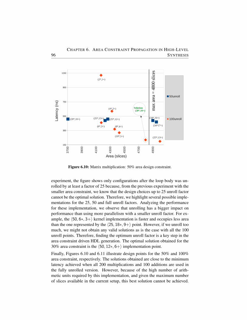
96CHAPTER 6. AREA CONSTRAINT PROPAGATION IN HIGH-LEVEL
SYNTHESIS
m_50
Page 1
name area50unroll
20MUL_10ADD 3705 time smaller SOLtime smaller SOL 510 7795 20*,10+ 100*, 50+25MUL_12ADD 4266 time smaller SOLtime smaller SOL 510 7795 25*,12+ 100*, 50+
25MUL_13ADD_SOL 4228 88 76 490 7775 25*,13+ 100*, 50+34MUL_16ADD 4900 N/A ERROR: !DSP (100>80)490 7775 34*,16+ 100*, 50+34MUL_17ADD 4950 N/A ERROR: !DSP (102>80)470 7755 34*,17+ 100*, 50+
100unroll #VALUE! 2MUL_1ADD 4171 1120 8405 2*,1+ 200*,100+4MUL_2ADD 4324 620 7905 4*,2+ 200*,100+6MUL_3ADD 4174 86 18 460 7745 6*,3+ 200*,100+8MUL_4ADD 4362 90 24 370 7655 8*,4+ 200*,100+
10MUL_5ADD 4427 92 30 320 7605 10*, 5+ 200*,100+20MUL_10ADD 4797 99 60 220 7505 20*,10+ 200*,100+25MUL_13ADD 5000 N/A ERROR:!sites(FF 19290>19200)200 7485 25*,13+ 200*,100+
37
00
39
00
41
00
43
00
45
00
47
00
49
00
150
350
550
750
950
1150
50unroll
100unroll
Area (slices)
Late
ncy
(n
s)
max
are
a =
4800
slic
es
(6*,3+)
Solution (20*,10+)
(8*,4+)
(34*,16+)
(25*,13+)
(25*,12+)(25*,13+)(20*,10+)
(4*,2+)
(2*,1+)
(34*17+)
(10*,5+)
Figure 6.10: Matrix multiplication: 50% area design constraint.
experiment, the figure shows only configurations after the loop body was un-rolled by at least a factor of 25 because, from the previous experiment with thesmaller area constraint, we know that the design choices up to 25 unroll factorcannot be the optimal solution. Therefore, we highlight several possible imple-mentations for the 25, 50 and full unroll factors. Analyzing the performancefor these implementation, we observe that unrolling has a bigger impact onperformance than using more parallelism with a smaller unroll factor. For ex-ample, the 〈50, 6∗, 3+〉 kernel implementation is faster and occupies less areathan the one represented by the 〈25, 18∗, 9+〉 point. However, if we unroll toomuch, we might not obtain any valid solutions as is the case with all the 100unroll points. Therefore, finding the optimum unroll factor is a key step in thearea constraint driven HDL generation. The optimal solution obtained for the30% area constraint is the 〈50, 12∗, 6+〉 implementation point.
Finally, Figures 6.10 and 6.11 illustrate design points for the 50% and 100%area constraint, respectively. The solutions obtained are close to the minimumlatency achieved when all 200 multiplications and 100 additions are used inthe fully unrolled version. However, because of the high number of arith-metic units required by this implementation, and given the maximum numberof slices available in the current setup, this best solution cannot be achieved.

6.4. EXPERIMENTAL RESULTS 97
m_100
Page 1
name area 7285100 unroll
40MUL_20ADD 7845 81 120 170 745550MUL_24ADD 8484 88 148 170 7455
50MUL_25ADD_SOL 8470 88 150 160 744567MUL_33ADD 9700 N/A ERROR: !DSP (200>160)160 744567MUL_34ADD 9800 N/A ERROR: !DSP (202>160)150 7435
MAX 9900 130
78
00
83
00
88
00
93
00
98
00
120
130
140
150
160
170
180
100 unroll
MAX
Area (slices)
Late
ncy
(n
s)
max
are
a =
9600
slic
es
Solution (50*,25+)
(67*,34+)
(200*,100+)
(40*,20+) (50*,24+)
(67*,33+)
Figure 6.11: Matrix multiplication: 100% area design constraint.
Therefore, a compiler that cannot handle area constraints and always fully un-roll loops to achieve the highest code parallelism using the maximum possibleresources will always fail to give a valid solution.
The same experiments were subsequently performed for the VectorSum casestudy, as well. Because this function does not contain any loops, only thesecond step of the algorithm was applied. This case study shows thus that thealgorithm can be applied also for applications that do not contain loops andthus it can be used in a general way. The solutions are summarized in Table6.1. For each constraint, we verified that the solutions are the optimal ones bychecking that allocating a smaller number of resources gives a bigger latencyfor the kernel execution time. At the same time, synthesizing the next solutionconfirmed that this fails to meet the area constraint.
Finally, we tested the FIR kernel that has as input an array of 32 values and 5parameters to compute 28 output values. Each of the output values is computedthus in a loop iterating 28 times. Therefore, the unroll factor set is composedof {1,2,4,7,14,28}. Table 6.1 summarizes the solutions obtained for all casestudies. The second column shows the area restriction for which the results aregiven. The third column shows the unroll factor obtained in the first step of thealgorithm while the next column gives the maximum operations of each type
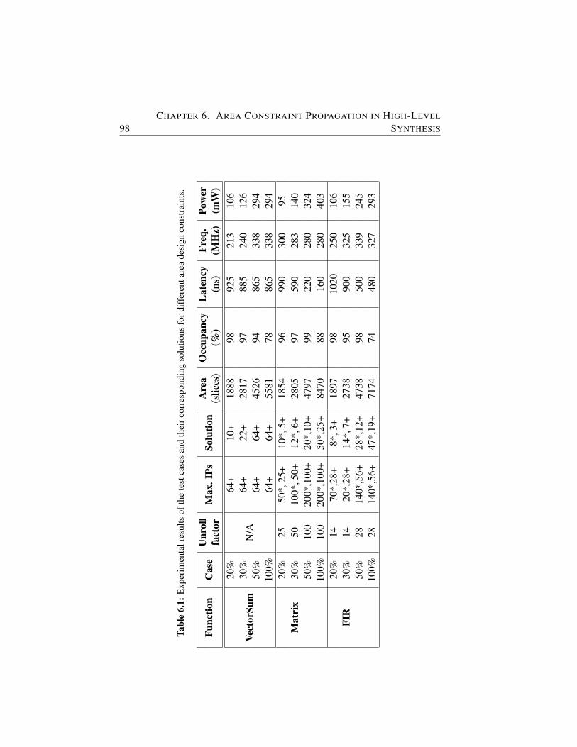
98CHAPTER 6. AREA CONSTRAINT PROPAGATION IN HIGH-LEVEL
SYNTHESIS
Tabl
e6.
1:E
xper
imen
talr
esul
tsof
the
test
case
san
dth
eirc
orre
spon
ding
solu
tions
ford
iffer
enta
rea
desi
gnco
nstr
aint
s.
Func
tion
Cas
eU
nrol
lM
ax.I
PsSo
lutio
nA
rea
Occ
upan
cyL
aten
cyFr
eq.
Pow
erfa
ctor
(slic
es)
(%)
(ns)
(MH
z)(m
W)
Vect
orSu
m
20%
N/A
64+
10+
1888
9892
521
310
630
%64
+22
+28
1797
885
240
126
50%
64+
64+
4526
9486
533
829
410
0%64
+64
+55
8178
865
338
294
Mat
rix
20%
2550
*,25
+10
*,5+
1854
9699
030
095
30%
5010
0*,5
0+12
*,6+
2805
9759
028
314
050
%10
020
0*,1
00+
20*,
10+
4797
9922
028
032
410
0%10
020
0*,1
00+
50*,
25+
8470
8816
028
040
3
FIR
20%
1470
*,28
+8*
,3+
1897
9810
2025
010
630
%14
20*,
28+
14*,
7+27
3895
900
325
155
50%
2814
0*,5
6+28
*,12
+47
3898
500
339
245
100%
2814
0*,5
6+47
*,19
+71
7474
480
327
293
6.5. CONCLUSION AND FUTURE RESEARCH 99
that could be executed in parallel for the previous unroll factor. The solutionof the second step of the algorithm for how many instances to use for eachoperation is shown in the fifth column. The next two columns highlight thenumber of slices the obtained solution takes as well as how much of the avail-able area for the experiment is used. Kernel latency and frequency informationare showed in columns eight and nine. This maximum frequency reported isobtained after behavioral synthesis. We do not report the post place and routefrequency because we set the target clock cycle to 6.66 ns. This restriction isimposed by the 150 MHz frequency required by the MOLEN static part.
It is important to look at the power consumption and how this is influenced bythe size of the generated implementation. The dynamic power consumed bythe unoptimized, initial kernel implementations (i.e., using only one IP of eachtype and not unrolling) is 81 mW, 8 mW, and 38mW for the vector summation,the matrix, and the FIR function, respectively. The power consumption for thesolution points for the experimented area constraints is given in the last columnof the results table. The power data offers another motivation why a hardwarecompiler should be able to generate different hardware implementation basedon different input constraints. We mostly discussed in this chapter the casewhere the user would want to map different kernels on the reconfigurable areaand optimize the performance. However, using the area as a design constraint,the user could just as well optimize the power consumption. This is especiallytrue for cases when the area increases rapidly, but only with a small increasein performance. For example, consider the vector summation solutions for the20% and 100% experiments. The speedup of the second compared to the firstis small, i.e., 1.1x, however, the increase in power is 2.8x. If the performanceof the system is not critical, the designer could choose to restrict the area toreduce the power consumption. Therefore, the presented algorithm could beused to minimize the power consumption as well, not only the performance.Nevertheless, a formal power model is needed in order to include the powerconstraint in the decision model. Such an extension is part of the future workof this approach.
6.5 Conclusion and Future Research
In this chapter, we presented an optimization algorithm to compute the optimalunroll factor and the optimum allocation of resources during the HLL-to-HDLgeneration process when this is subject to area constraints. The described al-gorithm was added to an existing C-to-VHDL hardware compiler, and three
100CHAPTER 6. AREA CONSTRAINT PROPAGATION IN HIGH-LEVEL
SYNTHESIS
case studies were used to validate the optimization. The experiments showedthat the generated solutions are mapped into the available area at an occupancyrate between 74% and 99%. Furthermore, these solutions provide the best ex-ecution time when compared to the other solutions that satisfy the same areaconstraint. Furthermore, a reduction in design time of 42x on average can beachieved when these parameters are chosen automatically by the compiler.
Future research includes analyzing other applications and investigating howdifferent graph characteristics influence the optimization presented. Anothermodel extension involves dealing with variable loop bounds. In addition, moreaccurate prediction models for the wiring increase as well as for the powerconsumption are needed.
Note.
The content of this chapter is based on the following paper:
R. Nane, V.M. Sima, K.L.M. Bertels, Area Constraint Propagation in HighLevel Synthesis, 11th IEEE International Conference on Field-ProgrammableTechnology (FPT 2012), Seoul, South Korea, December 2012.
7A Lightweight Speculative and
Predicative Scheme for HW Execution
IF-CONVERSION is a known software technique to speedup applicationscontaining conditional expressions and targeting processors with predi-cation support. However, the success of this scheme is highly dependent
on the structure of the if-statements, i.e., if they are balanced or unbalanced,as well as on the path taken at run-time. Therefore, the predication schemedoes not always provide a better execution time than the conventional jumpscheme. In this chapter, we present an algorithm that leverages the benefitsof both jump and predication schemes adapted for hardware execution. Theresults show that performance degradation is not possible anymore for the un-balanced if-statements as well as a speedup between 4% and 21% for all testcases.
7.1 Introduction
As the increase in frequency of the general-purpose processors is becomingsmaller and harder to obtain, new ways of providing performance are investi-gated. One of the promising possibilities to improve the system performanceis to generate dedicated hardware for the computational-intensive parts of theapplications. As writing hardware involves a huge effort and needs special ex-pertise, compilers that translate directly from high-level languages to hardwarelanguages have to be available before this method is widely adopted. As C andVHDL are the most popular used languages in their fields, of embedded andhardware system development respectively, we will focus on compilers for C-to-VHDL. The algorithm presented here can be applied in theory to any suchcompiler. A C-to-VHDL compiler can share a significant part with a compiler
101
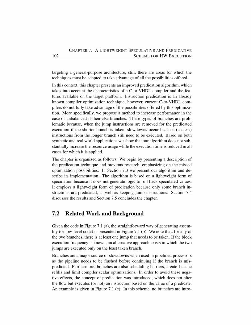
102CHAPTER 7. A LIGHTWEIGHT SPECULATIVE AND PREDICATIVE
SCHEME FOR HW EXECUTION
targeting a general-purpose architecture, still, there are areas for which thetechniques must be adapted to take advantage of all the possibilities offered.
In this context, this chapter presents an improved predication algorithm, whichtakes into account the characteristics of a C-to-VHDL compiler and the fea-tures available on the target platform. Instruction predication is an alreadyknown compiler optimization technique; however, current C-to-VHDL com-pilers do not fully take advantage of the possibilities offered by this optimiza-tion. More specifically, we propose a method to increase performance in thecase of unbalanced if-then-else branches. These types of branches are prob-lematic because, when the jump instructions are removed for the predicatedexecution if the shorter branch is taken, slowdowns occur because (useless)instructions from the longer branch still need to be executed. Based on bothsynthetic and real world applications we show that our algorithm does not sub-stantially increase the resource usage while the execution time is reduced in allcases for which it is applied.
The chapter is organized as follows. We begin by presenting a description ofthe predication technique and previous research, emphasizing on the missedoptimization possibilities. In Section 7.3 we present our algorithm and de-scribe its implementation. The algorithm is based on a lightweight form ofspeculation because it does not generate logic to roll back speculated values.It employs a lightweight form of predication because only some branch in-structions are predicated, as well as keeping jump instructions. Section 7.4discusses the results and Section 7.5 concludes the chapter.
7.2 Related Work and Background
Given the code in Figure 7.1 (a), the straightforward way of generating assem-bly (or low-level code) is presented in Figure 7.1 (b). We note that, for any ofthe two branches, there is at least one jump that needs to be taken. If the blockexecution frequency is known, an alternative approach exists in which the twojumps are executed only on the least taken branch.
Branches are a major source of slowdowns when used in pipelined processorsas the pipeline needs to be flushed before continuing if the branch is mis-predicted. Furthermore, branches are also scheduling barriers, create I-cacherefills and limit compiler scalar optimizations. In order to avoid these nega-tive effects, the concept of predication was introduced, which does not alterthe flow but executes (or not) an instruction based on the value of a predicate.An example is given in Figure 7.1 (c). In this scheme, no branches are intro-
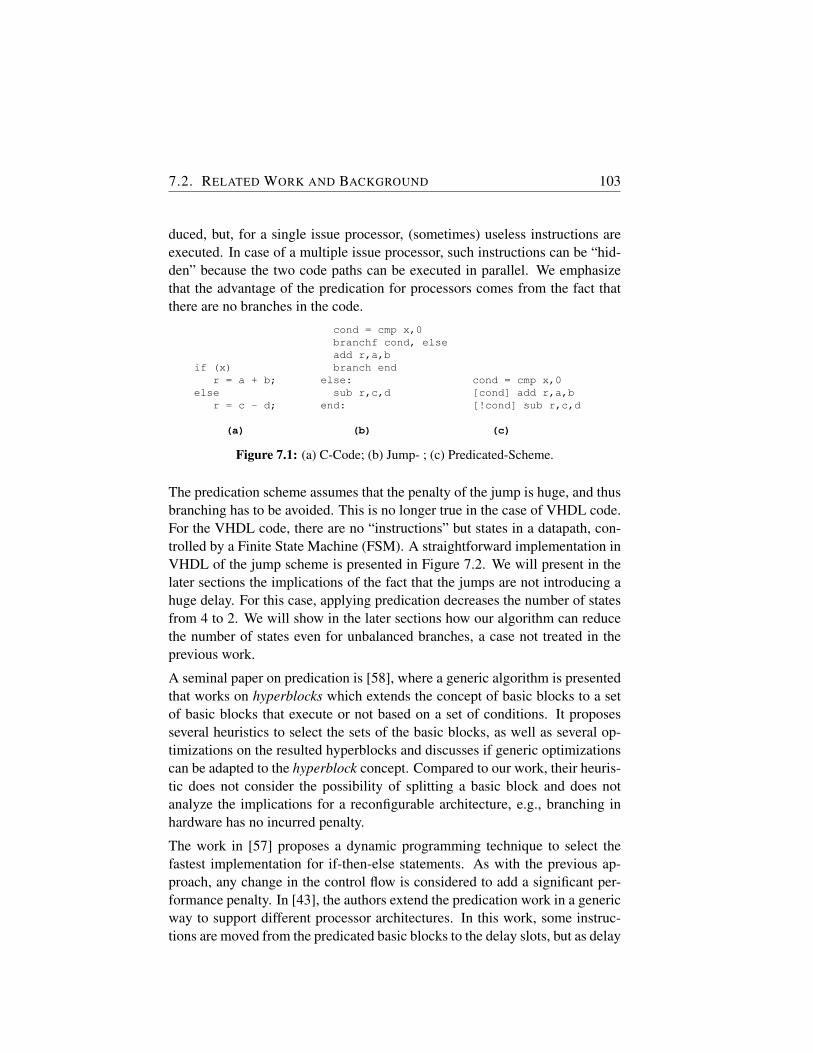
7.2. RELATED WORK AND BACKGROUND 103
duced, but, for a single issue processor, (sometimes) useless instructions areexecuted. In case of a multiple issue processor, such instructions can be “hid-den” because the two code paths can be executed in parallel. We emphasizethat the advantage of the predication for processors comes from the fact thatthere are no branches in the code.
if (x)r = a + b;
elser = c - d;
(a)
cond = cmp x,0branchf cond, elseadd r,a,bbranch end
else:sub r,c,d
end:
(b)
cond = cmp x,0[cond] add r,a,b[!cond] sub r,c,d
(c)
Figure 7.1: (a) C-Code; (b) Jump- ; (c) Predicated-Scheme.
The predication scheme assumes that the penalty of the jump is huge, and thusbranching has to be avoided. This is no longer true in the case of VHDL code.For the VHDL code, there are no “instructions” but states in a datapath, con-trolled by a Finite State Machine (FSM). A straightforward implementation inVHDL of the jump scheme is presented in Figure 7.2. We will present in thelater sections the implications of the fact that the jumps are not introducing ahuge delay. For this case, applying predication decreases the number of statesfrom 4 to 2. We will show in the later sections how our algorithm can reducethe number of states even for unbalanced branches, a case not treated in theprevious work.
A seminal paper on predication is [58], where a generic algorithm is presentedthat works on hyperblocks which extends the concept of basic blocks to a setof basic blocks that execute or not based on a set of conditions. It proposesseveral heuristics to select the sets of the basic blocks, as well as several op-timizations on the resulted hyperblocks and discusses if generic optimizationscan be adapted to the hyperblock concept. Compared to our work, their heuris-tic does not consider the possibility of splitting a basic block and does notanalyze the implications for a reconfigurable architecture, e.g., branching inhardware has no incurred penalty.
The work in [57] proposes a dynamic programming technique to select thefastest implementation for if-then-else statements. As with the previous ap-proach, any change in the control flow is considered to add a significant per-formance penalty. In [43], the authors extend the predication work in a genericway to support different processor architectures. In this work, some instruc-tions are moved from the predicated basic blocks to the delay slots, but as delay

104CHAPTER 7. A LIGHTWEIGHT SPECULATIVE AND PREDICATIVE
SCHEME FOR HW EXECUTION
datapathstate_1:
cond = cmp x,0state_2:state_3:
r=a+b;state_4:
r=a-b;state_5:
.... -- code after if-statementFSM
state_1:next_state = state_2
state_2:if(cond)
next_state = state_3elsenext_state = state_4
state_3:next_state = state_5
state_4:next_state = state_5
state_5:....
Figure 7.2: Jump Scheme
slots are very limited in nature there is no extensive analysis performed aboutthis decision.
Regarding the C-to-VHDL compilers, we mention Altium’s C to Hardware(CHC) [8] and LegUp [18]. They translate functions that belong to the appli-cation’s computational-intensive parts in a hardware/software co-design envi-ronment. Neither of these compilers considers specifically predication coupledwith speculation during the generation of VHDL code.
7.3 Speculative and Predicative Algorithm
In this section, we describe the optimization algorithm based on two simple butrepresentative examples which illustrate the benefit of including Speculativeand Predicative Algorithm (SaPA) as a transformation in High-Level Synthesis(HLS) tools.
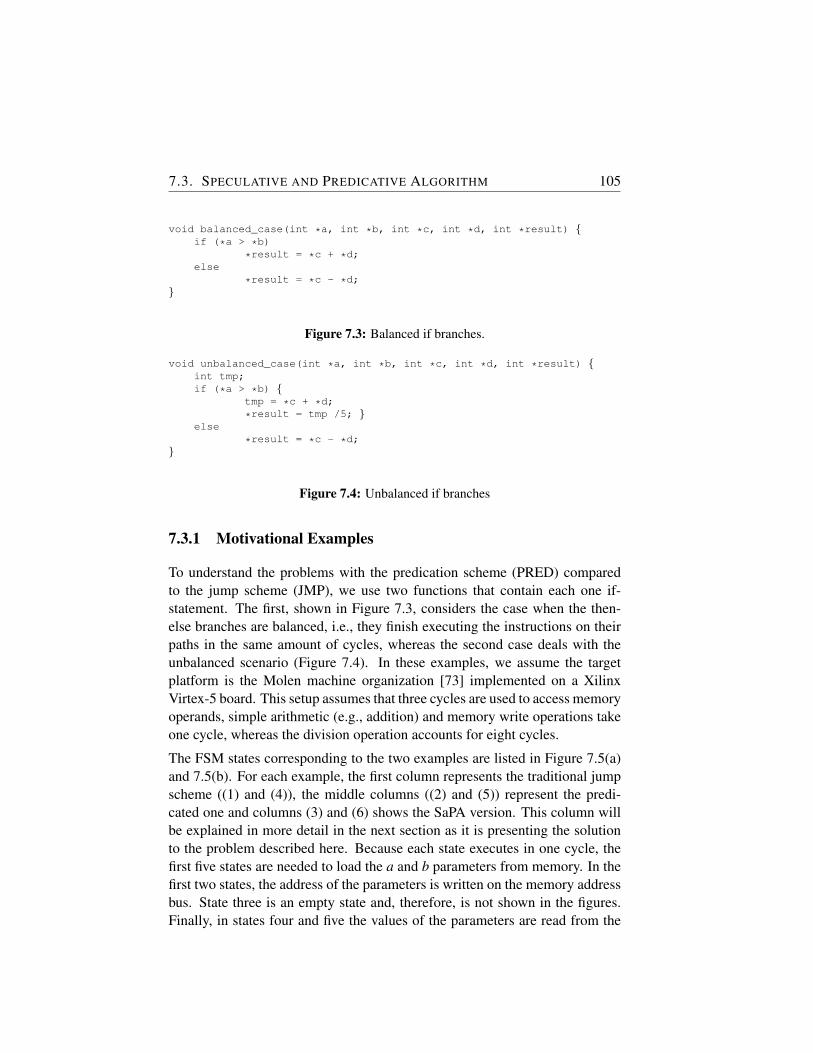
7.3. SPECULATIVE AND PREDICATIVE ALGORITHM 105
void balanced_case(int *a, int *b, int *c, int *d, int *result) {if (*a > *b)
*result = *c + *d;else
*result = *c - *d;}
Figure 7.3: Balanced if branches.
void unbalanced_case(int *a, int *b, int *c, int *d, int *result) {int tmp;if (*a > *b) {
tmp = *c + *d;
*result = tmp /5; }else
*result = *c - *d;}
Figure 7.4: Unbalanced if branches
7.3.1 Motivational Examples
To understand the problems with the predication scheme (PRED) comparedto the jump scheme (JMP), we use two functions that contain each one if-statement. The first, shown in Figure 7.3, considers the case when the then-else branches are balanced, i.e., they finish executing the instructions on theirpaths in the same amount of cycles, whereas the second case deals with theunbalanced scenario (Figure 7.4). In these examples, we assume the targetplatform is the Molen machine organization [73] implemented on a XilinxVirtex-5 board. This setup assumes that three cycles are used to access memoryoperands, simple arithmetic (e.g., addition) and memory write operations takeone cycle, whereas the division operation accounts for eight cycles.
The FSM states corresponding to the two examples are listed in Figure 7.5(a)and 7.5(b). For each example, the first column represents the traditional jumpscheme ((1) and (4)), the middle columns ((2) and (5)) represent the predi-cated one and columns (3) and (6) shows the SaPA version. This column willbe explained in more detail in the next section as it is presenting the solutionto the problem described here. Because each state executes in one cycle, thefirst five states are needed to load the a and b parameters from memory. In thefirst two states, the address of the parameters is written on the memory addressbus. State three is an empty state and, therefore, is not shown in the figures.Finally, in states four and five the values of the parameters are read from the
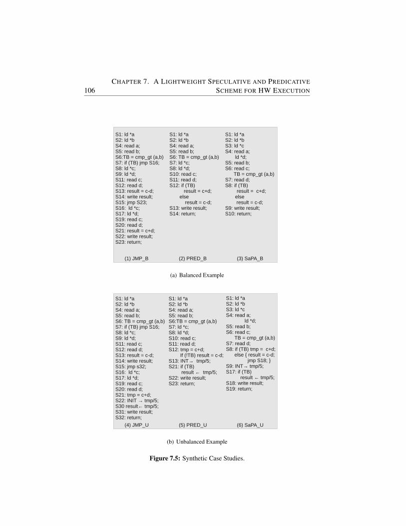
106CHAPTER 7. A LIGHTWEIGHT SPECULATIVE AND PREDICATIVE
SCHEME FOR HW EXECUTION
if (*a > *b)*result = *c + *d;
else*result = *c - *d;
S1: ld *a S2: ld *bS4: read a;S5: read b;S6:TB = cmp_gt (a,b)S7: if (TB) jmp S16;S8: ld *c;S9: ld *d; S11: read c;S12: read d;S13: result = c-d;S14: write result;S15: jmp S23;S16: ld *c;S17: ld *d; S19: read c;S20: read d;S21: result = c+d;S22: write result;S23: return;
S1: ld *a S2: ld *bS4: read a;S5: read b;S6: TB = cmp_gt (a,b)S7: ld *c;S8: ld *d; S10: read c;S11: read d;S12: if (TB)
result = c+d;else
result = c-d;S13: write result;S14: return;
S1: ld *a S2: ld *bS3: ld *cS4: read a; ld *d;S5: read b;S6: read c; TB = cmp_gt (a,b)S7: read d;S8: if (TB)
result = c+d; else result = c-d;S9: write result;S10: return;
(1) JMP_B (2) PRED_B (3) SaPA_B
(a) Balanced Example
S1: ld *a S2: ld *bS4: read a;S5: read b;S6: TB = cmp_gt (a,b)S7: if (TB) jmp S16;S8: ld *c;S9: ld *d; S11: read c;S12: read d;S13: result = c-d;S14: write result;S15: jmp s32;S16: ld *c;S17: ld *d; S19: read c;S20: read d;S21: tmp = c+d;S22: INIT → tmp/5;S30 result← tmp/5;S31: write result;S32: return;
S1: ld *a S2: ld *bS4: read a;S5: read b;S6:TB = cmp_gt (a,b)S7: ld *c;S8: ld *d; S10: read c;S11: read d;S12: tmp = c+d;
If (!TB) result = c-d;S13: INT→ tmp/5;S21: if (TB) result ← tmp/5;S22: write result;S23: return;
S1: ld *a S2: ld *bS3: ld *cS4: read a;
ld *d;S5: read b;S6: read c; TB = cmp_gt (a,b)S7: read d;S8: if (TB) tmp = c+d; else { result = c-d;
jmp S18; }S9: INT→ tmp/5;S17: if (TB)
result ← tmp/5;S18: write result;S19: return;
if (*a > *b) {tmp = *c + *d;*result = tmp / 5; }
else*result = *c - *d;
(4) JMP_U (5) PRED_U (6) SaPA_U
(b) Unbalanced Example
Figure 7.5: Synthetic Case Studies.
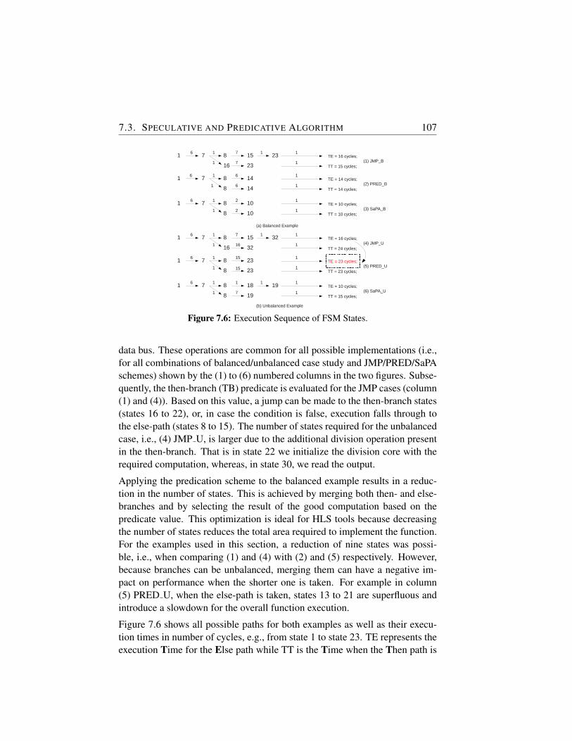
7.3. SPECULATIVE AND PREDICATIVE ALGORITHM 107
1 7 8 15 23
16 23
6 1 7 1TE = 16 cycles;
1
TT = 15 cycles; 11 7 (1) JMP_B
1 7 8 14
8 14
6 1 6TE = 14 cycles;
1
TT = 14 cycles; 11 6 (2) PRED_B
1 7 8 10
8 10
6 1TE = 10 cycles;
1
TT = 10 cycles; 11 2 (3) SaPA_B
1 7 8 15 32
16 32
6 1 7 1TE = 16 cycles;
1
TT = 24 cycles; 11 16 (4) JMP_U
1 7 8 23
8 23
6 1 15TE = 23 cycles;
1
TT = 23 cycles; 11 (5) PRED_U
1 7 8 18 19
8 19
6 1 1 1TE = 10 cycles;
1
TT = 15 cycles; 11 7 (6) SaPA_U
2
15
(a) Balanced Example
(b) Unbalanced Example
Figure 7.6: Execution Sequence of FSM States.
data bus. These operations are common for all possible implementations (i.e.,for all combinations of balanced/unbalanced case study and JMP/PRED/SaPAschemes) shown by the (1) to (6) numbered columns in the two figures. Subse-quently, the then-branch (TB) predicate is evaluated for the JMP cases (column(1) and (4)). Based on this value, a jump can be made to the then-branch states(states 16 to 22), or, in case the condition is false, execution falls through tothe else-path (states 8 to 15). The number of states required for the unbalancedcase, i.e., (4) JMP U, is larger due to the additional division operation presentin the then-branch. That is in state 22 we initialize the division core with therequired computation, whereas, in state 30, we read the output.
Applying the predication scheme to the balanced example results in a reduc-tion in the number of states. This is achieved by merging both then- and else-branches and by selecting the result of the good computation based on thepredicate value. This optimization is ideal for HLS tools because decreasingthe number of states reduces the total area required to implement the function.For the examples used in this section, a reduction of nine states was possi-ble, i.e., when comparing (1) and (4) with (2) and (5) respectively. However,because branches can be unbalanced, merging them can have a negative im-pact on performance when the shorter one is taken. For example in column(5) PRED U, when the else-path is taken, states 13 to 21 are superfluous andintroduce a slowdown for the overall function execution.
Figure 7.6 shows all possible paths for both examples as well as their execu-tion times in number of cycles, e.g., from state 1 to state 23. TE represents theexecution Time for the Else path while TT is the Time when the Then path is
108CHAPTER 7. A LIGHTWEIGHT SPECULATIVE AND PREDICATIVE
SCHEME FOR HW EXECUTION
taken. The upper part of the figure corresponds to the balanced if-function andthe lower for the unbalanced case. Furthermore, there is a one-to-one corre-spondence between the columns in Figure 7.5 and the scenarios in Figure 7.6.The numbers on the edges represent the number of cycles needed to reach thenext state shown. The last arrow in the paths represents the cycle required toexecute the return statement in the last state of the FSM. First, considering thebalanced flows, we observe that the predication scheme improves performancecompared to the jump scheme (i.e., (2) is better than (1)). This is because jumpinstructions are removed.
However, care has to be taken to avoid performance degradation when shorterpaths are taken. This is shown in Figure 7.6 (5) compared to (4), where the exe-cution time increased from 16 to 23 cycles. Therefore, for hardware executionthe predication scheme has to be adjusted to cope with unbalanced branches.This is described next.
7.3.2 Algorithm Description and Implementation
To alleviate the short branch problem from the PRED scheme, we need to in-troduce a jump statement when the shorter branch is finished. Fortunately, forhardware execution this is possible without any penalty in cycles as opposedto conventional processors. This extension to the predicated scheme is shownin state S10 of Figure 7.5 (6). Including jump instructions in the FSM when-ever a shorter path has finished guarantees that no extra cycles are wasted oninstructions that are superfluous for the path taken. This is possible because,in hardware execution, there is no penalty when performing jumps. This moti-vates that this transformation can be applied for hardware generation becausea hardware kernel is always seen as running on an n-issue slot processor witha jump penalty equal to 0. Furthermore, the flows in (3) and (6) of Figure 7.6show that speculation improves performance even more by starting the branchoperations before the predicate is evaluated. It is important to note that specu-lation in the case of hardware execution comes without any penalty as we donot have to roll back if the predicate value did not select the proper branch forexecution. In hardware we can use more resources to accommodate specula-tive operations, i.e., sacrifice area, in favor of improving performance.
The compiler modifications required to implement the algorithm are shown inFigure 7.7 in the lower dashed rectangle. In the upper part of the figure, theglobal flow of the DWARV 2.0 compiler is shown. Here, standard and cus-tom engines performing various transformations and optimizations are calledsequentially to perform the code translation from C to VHDL. In this existing
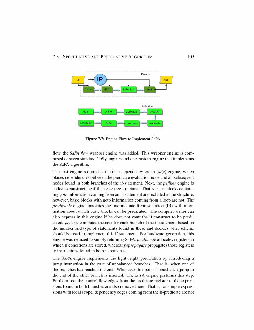
7.3. SPECULATIVE AND PREDICATIVE ALGORITHM 109
CFrontCFront
.c.c IRIR
SSASSA SaPA flowSaPA flow emitemit
.vhdl.vhdl
DWARV
SaPA flow
schedulerscheduler
pefilterpefilter predicablepredicable pecostspecosts
peallocatepeallocatepepropagatepepropagateSaPASaPA
ddgddg
Figure 7.7: Engine Flow to Implement SaPA.
flow, the SaPA flow wrapper engine was added. This wrapper engine is com-posed of seven standard CoSy engines and one custom engine that implementsthe SaPA algorithm.
The first engine required is the data dependency graph (ddg) engine, whichplaces dependencies between the predicate evaluation node and all subsequentnodes found in both branches of the if-statement. Next, the pefilter engine iscalled to construct the if-then-else tree structures. That is, basic blocks contain-ing goto information coming from an if-statement are included in the structure,however, basic blocks with goto information coming from a loop are not. Thepredicable engine annotates the Intermediate Representation (IR) with infor-mation about which basic blocks can be predicated. The compiler writer canalso express in this engine if he does not want the if-construct to be predi-cated. pecosts computes the cost for each branch of the if-statement based onthe number and type of statements found in these and decides what schemeshould be used to implement this if-statement. For hardware generation, thisengine was reduced to simply returning SaPA. peallocate allocates registers inwhich if conditions are stored, whereas pepropagate propagates those registersto instructions found in both if-branches.
The SaPA engine implements the lightweight predication by introducing ajump instruction in the case of unbalanced branches. That is, when one ofthe branches has reached the end. Whenever this point is reached, a jump tothe end of the other branch is inserted. The SaPA engine performs this step.Furthermore, the control flow edges from the predicate register to the expres-sions found in both branches are also removed here. That is, for simple expres-sions with local scope, dependency edges coming from the if-predicate are not
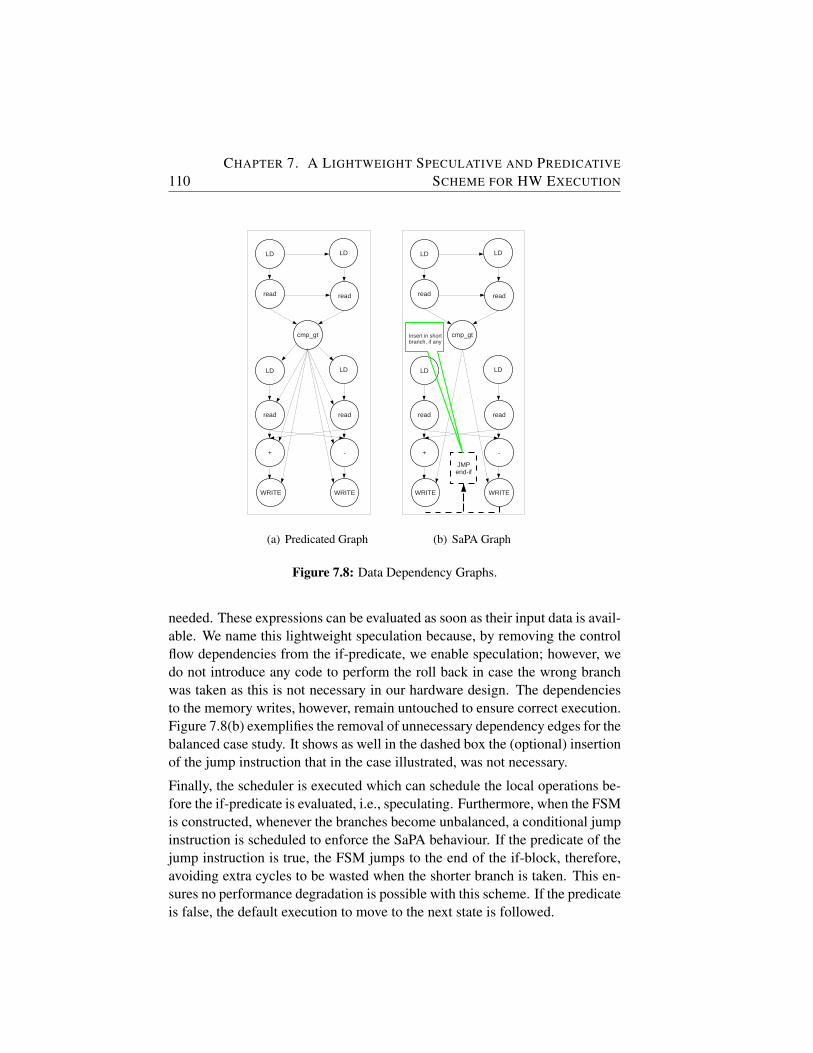
110CHAPTER 7. A LIGHTWEIGHT SPECULATIVE AND PREDICATIVE
SCHEME FOR HW EXECUTION
State 1: ld *a State 2: ld *bState 4: read a;State 5: read b;State 6: then_branch = cmp_gt (a,b)State 7: if (then_branch) jmp state 16;State 8: ld *c;State 9: ld *d; State 11: read c;State 12: read d;State 13: result = c-d;State 14: write result;State 15: jmp state 21;State 16: ld *c;State 17: ld *d; State 19: read c;State 20: read d;State 21: result = c+d;State 22: write result;State 23: return;
LD LD
read read
cmp_gt
LD LD
read read
+ -
WRITE WRITE
(a) Predicated Graph
State 1: ld *a State 2: ld *bState 4: read a;State 5: read b;State 6: then_branch = cmp_gt (a,b)State 7: if (then_branch) jmp state 16;State 8: ld *c;State 9: ld *d; State 11: read c;State 12: read d;State 13: result = c-d;State 14: write result;State 15: jmp state 21;State 16: ld *c;State 17: ld *d; State 19: read c;State 20: read d;State 21: result = c+d;State 22: write result;State 23: return;
LD LD
read read
cmp_gt
LD LD
read read
+ -
WRITE WRITE
JMPend-if
Insert in short branch, if any
(b) SaPA Graph
Figure 7.8: Data Dependency Graphs.
needed. These expressions can be evaluated as soon as their input data is avail-able. We name this lightweight speculation because, by removing the controlflow dependencies from the if-predicate, we enable speculation; however, wedo not introduce any code to perform the roll back in case the wrong branchwas taken as this is not necessary in our hardware design. The dependenciesto the memory writes, however, remain untouched to ensure correct execution.Figure 7.8(b) exemplifies the removal of unnecessary dependency edges for thebalanced case study. It shows as well in the dashed box the (optional) insertionof the jump instruction that in the case illustrated, was not necessary.
Finally, the scheduler is executed which can schedule the local operations be-fore the if-predicate is evaluated, i.e., speculating. Furthermore, when the FSMis constructed, whenever the branches become unbalanced, a conditional jumpinstruction is scheduled to enforce the SaPA behaviour. If the predicate of thejump instruction is true, the FSM jumps to the end of the if-block, therefore,avoiding extra cycles to be wasted when the shorter branch is taken. This en-sures no performance degradation is possible with this scheme. If the predicateis false, the default execution to move to the next state is followed.
7.4. EXPERIMENTAL RESULTS 111
7.4 Experimental Results
The environment used for the experiments is composed of three main parts:i) The C-to-VHDL DWARV 2.0 compiler (see Chapter 4), extended with theflow presented in Section 7.3, ii) the Xilinx ISE 12.2 synthesis tools, and iii)the Xilinx Virtex5 ML510 development board. This board contains a Virtex5 xc5vfx130t FPGA consisting of 20,480 slices and 2 PowerPC processors.To test the performance of the algorithm presented, we used seven functions.Two are the simple synthetic cases introduced in the previous section whilethe other five were extracted from a library of real world applications. Theseapplications contain both balanced and unbalanced if-branches.
Figure 7.9 show the speedups of the PRED and SaPA schemes comparedto the JMP scheme. The balanced function shows how much speedup isgained by combining the predication scheme with speculation. Similar tothis, the speedup of the unbalanced function, tested with inputs that selectthe longer branch (LBT), shows a performance improvement compared to theJMP scheme due to speculation. However, when the shorter branch is taken(SBT), the PRED scheme suffers from performance degradation. Applyingthe SaPA scheme in this case allows the FSM to jump when the shorter branchfinishes and, therefore, obtaining the 1.14x speedup.
The execution times for both schemes for the gcd function are the same be-cause both paths found in this arithmetic function have length one, i.e., theyperform only one subtraction each. Therefore, the only benefit is derived fromremoving the jump-instruction following the operands comparison. It is impor-tant to note that applying speculation is useful in all cases where both branchesand the if-predicate computation take more than one cycle. Otherwise, thePRED scheme is enough to obtain the maximum speedup. Nevertheless, thespeedup that can obtained by simply predicating the if-statement and thus sav-ing one jump instruction per iteration can be considerable, e.g., 20% whenthe gcd input numbers are 12365400 and 906. mergesort provided a test casewith a balanced if-structure where each of the paths contains more than oneinstruction. Therefore, the benefit of applying SaPA was greater than using thePRED scheme. This example confirms that whenever the paths are balanced,the application can not be slowed-down.
Finally, the last three cases show results obtained for unbalanced cases withinputs that trigger the shorter branches in these examples. As a result, forall these functions the PRED scheme generates hardware that performs worsethan the simple JMP strategy. Applying the SaPA algorithm and introducing
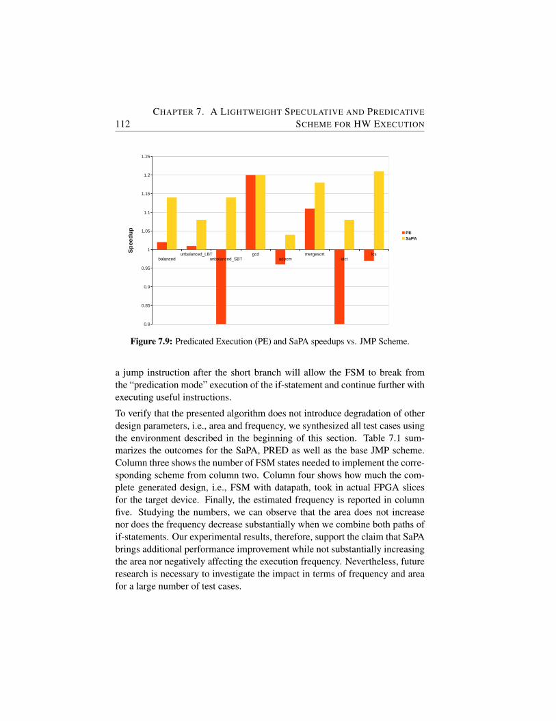
112CHAPTER 7. A LIGHTWEIGHT SPECULATIVE AND PREDICATIVE
SCHEME FOR HW EXECUTIONResults_chart
Page 1
Speed-up1 415 PE
PE 1.02 405 balanced 1.02 1.14SPPA 1.14 365 unbalanced_LBT 1.01 1.08
unbalanced_SBT 0.59 1.141.2 1.2
Speed-up 0.96 1.041 715 1.11 1.18
PE 1.01 705 0.79 1.08SPPA 1.08 665 0.97 1.21
Speed-up1 415
PE 0.59 705SPPA 1.14 365
REAL APPLICATIONS GCD Speed-up
1 820145PE 1.20 683505
SPPA 1.20 683505
Speed-up1 342965
PE 0.96 355515SPPA 1.04 330515
Speed-up
1 5585PE 1.11 5035
SPPA 1.18 4715
Speed-up1
PE 0.79 SPPA 1.08
LCS Speed-up1
PE 0.97 SPPA 1.21
simplePE latency(ns)noPE SaPA
gcdunbalancedPE_LBT latency(ns) adpcm
noPE mergesortidctlcs
unbalancedPE_SBT latency(ns)noPE
latency(ns)noPE
adpcm latency(ns)noPE
mergesort latency(ns)noPE
idct latency(ns)noPE
latency(ns)noPE
balancedunbalanced_LBT
unbalanced_SBTgcd
adpcmmergesort
idctlcs
0.8
0.85
0.9
0.95
1
1.05
1.1
1.15
1.2
1.25
PESaPA
Sp
ee
du
p
Figure 7.9: Predicated Execution (PE) and SaPA speedups vs. JMP Scheme.
a jump instruction after the short branch will allow the FSM to break fromthe “predication mode” execution of the if-statement and continue further withexecuting useful instructions.
To verify that the presented algorithm does not introduce degradation of otherdesign parameters, i.e., area and frequency, we synthesized all test cases usingthe environment described in the beginning of this section. Table 7.1 sum-marizes the outcomes for the SaPA, PRED as well as the base JMP scheme.Column three shows the number of FSM states needed to implement the corre-sponding scheme from column two. Column four shows how much the com-plete generated design, i.e., FSM with datapath, took in actual FPGA slicesfor the target device. Finally, the estimated frequency is reported in columnfive. Studying the numbers, we can observe that the area does not increasenor does the frequency decrease substantially when we combine both paths ofif-statements. Our experimental results, therefore, support the claim that SaPAbrings additional performance improvement while not substantially increasingthe area nor negatively affecting the execution frequency. Nevertheless, futureresearch is necessary to investigate the impact in terms of frequency and areafor a large number of test cases.
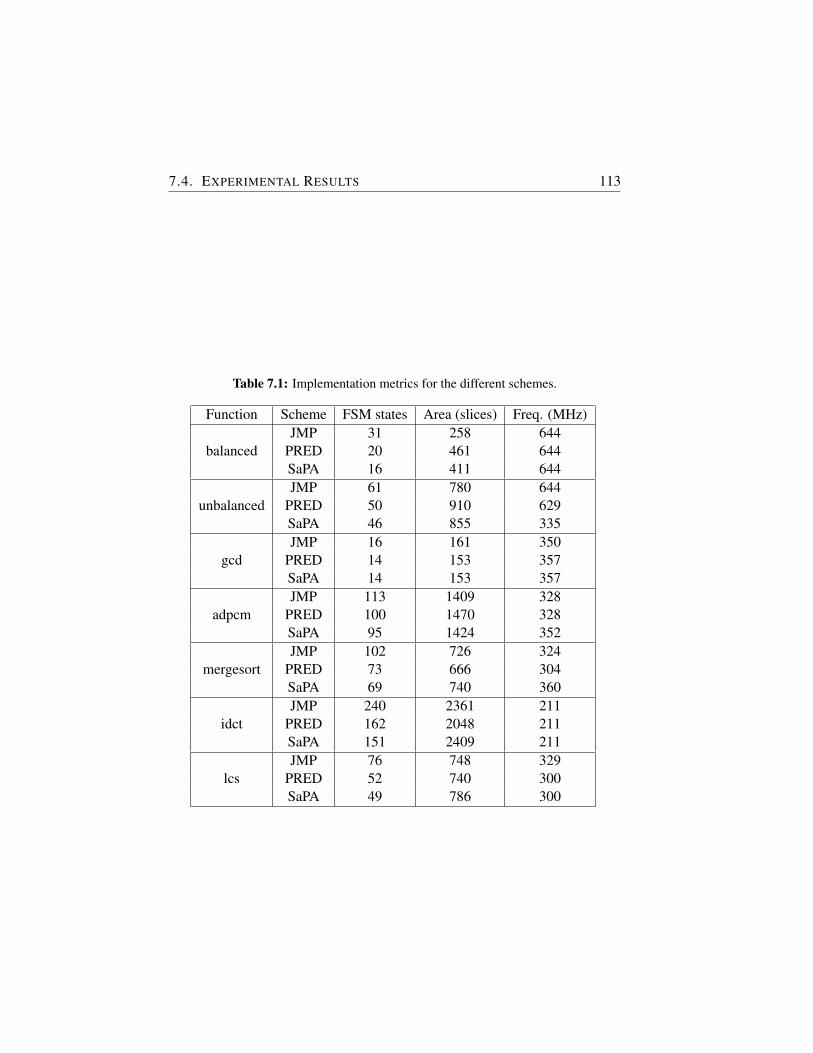
7.4. EXPERIMENTAL RESULTS 113
Table 7.1: Implementation metrics for the different schemes.
Function Scheme FSM states Area (slices) Freq. (MHz)
balancedJMP 31 258 644
PRED 20 461 644SaPA 16 411 644
unbalancedJMP 61 780 644
PRED 50 910 629SaPA 46 855 335
gcdJMP 16 161 350
PRED 14 153 357SaPA 14 153 357
adpcmJMP 113 1409 328
PRED 100 1470 328SaPA 95 1424 352
mergesortJMP 102 726 324
PRED 73 666 304SaPA 69 740 360
idctJMP 240 2361 211
PRED 162 2048 211SaPA 151 2409 211
lcsJMP 76 748 329
PRED 52 740 300SaPA 49 786 300
114CHAPTER 7. A LIGHTWEIGHT SPECULATIVE AND PREDICATIVE
SCHEME FOR HW EXECUTION
7.5 Conclusion
In this chapter, we argued that the typical JMP and PRED schemes found inconventional processors are not performing ideally when we consider hard-ware execution. The problem with the first is that we lose important cycles tojump from the state where the if-condition is evaluated to the correct branchstate corresponding to the path chosen for execution. The PRED schemesolves this issue; however, it suffers from performance degradation when theif-branches are unbalanced.
To combine the advantages of both schemes, we presented a lightweight spec-ulative and predicative algorithm which does predication in the normal way;however, it introduces a jump instruction at the end of the shorter if-branchto cope with the unbalanced situation. Furthermore, to leverage the hardwareparallelism and the abundant resources, SaPA also performs partial specula-tion, i.e., no roll back necessary. This gains extra cycles in performance whenthe if-predicates take more than one cycle to evaluate.
We demonstrated based on two synthetic examples the benefit of this optimiza-tion and we validated it using five real world functions. The results show thatperformance degradation will not occur anymore for unbalanced if-statementsand that the observed speedups range from 4% to 21%. Therefore, SaPA is atransformation that should be considered for inclusion in any HLS tool. Futureresearch will analyze the impact of SaPA on a large number of kernels andinvestigate if any systematic relation can be observed between the input pa-rameters (e.g., number of instructions per path or nested ifs) and the measuredhardware metrics (i.e., area, frequency).
Note.
The content of this chapter is based on the following paper:
R. Nane, V.M. Sima, K.L.M. Bertels, A Lightweight Speculative and Pred-icative Scheme for Hardware Execution, IEEE International Conference onReConFigurable Computing and FPGAs (ReConFig 2012), Cancun, Mexico,December 2012.

8DWARV 3.0: Relevant Hardware
Compiler Optimizations
IN this chapter, we discuss several optimizations that have a great potentialof improving the performance of DWARV2.0. In particular, we discuss inSection 8.2 period-aware scheduling and memory space allocation hard-
ware specific optimizations, as well as an optimization to distribute the singleconditional code register to selection operations in order to take advantage ofthe inherent hardware space locality propriety. Furthermore, in Section 8.3 weinvestigate several existing optimizations, available in CoSy as default engines,to assess the impact of using an optimization intended for generating assemblycode in a hardware compiler. Software pipelining is one such optimization.
8.1 Introduction
In Chapter 4, we presented the DWARV2.0 compiler and described how it isimplemented using the CoSy compiler framework. This first CoSy version in-cluded only basic code transformations, such as common subexpression elim-ination or static single assignment, but no other more advanced optimizationswere analyzed and integrated in DWARV2.0. As a result, the performance ofthis version (i.e., 3.0) of the compiler greatly increased by using both hard-ware specific optimizations as well as studying and integrating the standardCoSy optimizations into DWARV.
In this chapter, we consider these two types of optimization sources and de-scribe how the identified optimizations were integrated. First, we look at op-timizations designed specially for the hardware generation process. In this re-spect, we consider two optimizations that have the role to increase the usabilityand applicability of generated hardware modules in the context of reconfig-
115

116CHAPTER 8. DWARV 3.0: RELEVANT HARDWARE COMPILER
OPTIMIZATIONS
urable computing. The goal is to be able to exploit the flexibility offered by aconfigurable hardware platform to implement different operating frequenciesand different memory system architectures.
These optimizations are period-aware scheduling, also called operation chain-ing, and memory space allocation optimization, respectively. The first has theclock period of the module as a design parameter and performs an operationscheduling within clock cycles. Concretely, it optimizes the number of cy-cles the design requires to complete execution. That is, if two dependent andsubsequent operations (i.e., they are the vertexes of a dependency edge in thedata dependency graph) can both complete execution in a time smaller than thegiven clock period for the system, then they can be placed in the same cycle. Ifthat is not the case, then for these two operations at least two cycles are neededto finish execution. The second optimization relates to the designed memorysystem architecture, that is, it allows the compiler to partition the hardware’smemory array parameters into different system memory banks to take full ad-vantage of a distributed memory system architecture that is typically availableon a reconfigurable platform.
In addition, we also want to investigate how existing optimizations designedfor the generation of assembly code can perform when integrated into a com-piler that generates Hardware Description Language (HDL). This is very use-ful to leverage the vast amount of CoSy framework standard optimizations. Insection 8.3, we present work performed with M.Slotema in the context of hismaster project that investigates these optimizations individually to assess whatcontribution a particular transformation has on the generated hardware.
8.2 Hardware-Specific Optimizations
In this section, we provide implementation details of how we integrated intoDWARV3.0 the distributed condition code, operation chaining and memoryspace allocation hardware specific optimizations.
Distributed Condition Codes
One of the advantages that hardware devices such as FPGAs have over conven-tional CPUs is their inherent predication support. Because of this feature, weshowed in Chapter 7 that a High-Level Synthesis (HLS) tool targeting FPGAsshould consider an optimization pass that performs if-conversion to enable thepredicated execution. This was demonstrated in the same chapter, where a
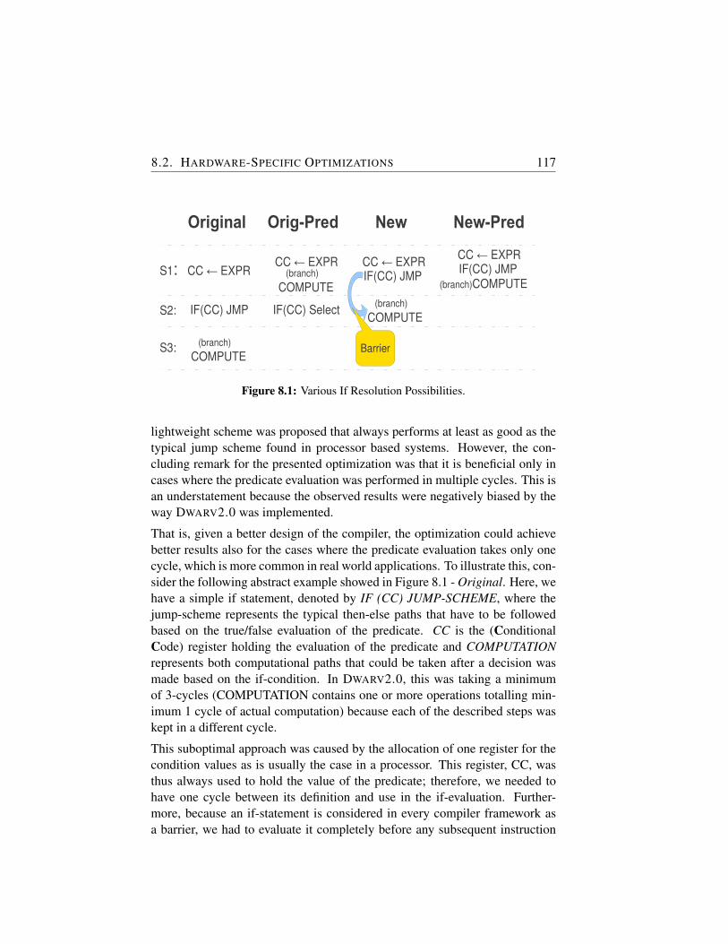
8.2. HARDWARE-SPECIFIC OPTIMIZATIONS 117
Original
CC EXPR←S1:
IF(CC) JMPS2:
(branch)COMPUTE
S3:
Orig-Pred
CC EXPR←
IF(CC) Select
(branch)COMPUTE
New
CC EXPR← IF(CC) JMP
(branch)COMPUTE
New-Pred
CC EXPR← IF(CC) JMP
(branch)COMPUTE
Barrier
Figure 8.1: Various If Resolution Possibilities.
lightweight scheme was proposed that always performs at least as good as thetypical jump scheme found in processor based systems. However, the con-cluding remark for the presented optimization was that it is beneficial only incases where the predicate evaluation was performed in multiple cycles. This isan understatement because the observed results were negatively biased by theway DWARV2.0 was implemented.
That is, given a better design of the compiler, the optimization could achievebetter results also for the cases where the predicate evaluation takes only onecycle, which is more common in real world applications. To illustrate this, con-sider the following abstract example showed in Figure 8.1 - Original. Here, wehave a simple if statement, denoted by IF (CC) JUMP-SCHEME, where thejump-scheme represents the typical then-else paths that have to be followedbased on the true/false evaluation of the predicate. CC is the (ConditionalCode) register holding the evaluation of the predicate and COMPUTATIONrepresents both computational paths that could be taken after a decision wasmade based on the if-condition. In DWARV2.0, this was taking a minimumof 3-cycles (COMPUTATION contains one or more operations totalling min-imum 1 cycle of actual computation) because each of the described steps waskept in a different cycle.
This suboptimal approach was caused by the allocation of one register for thecondition values as is usually the case in a processor. This register, CC, wasthus always used to hold the value of the predicate; therefore, we needed tohave one cycle between its definition and use in the if-evaluation. Further-more, because an if-statement is considered in every compiler framework asa barrier, we had to evaluate it completely before any subsequent instruction
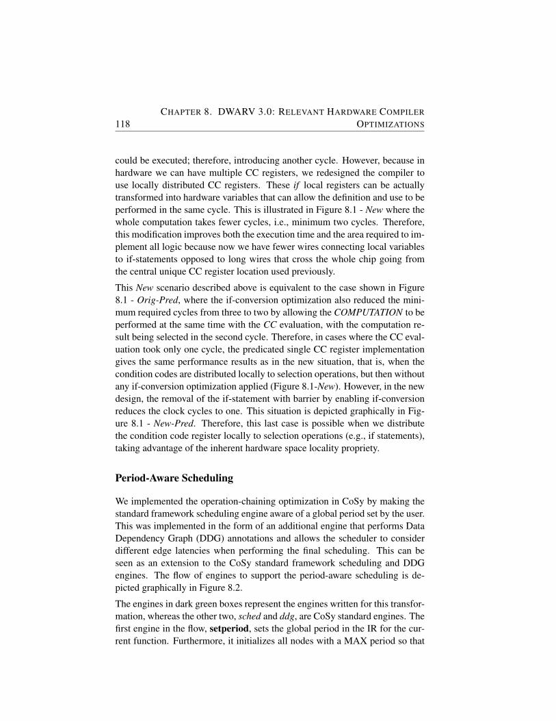
118CHAPTER 8. DWARV 3.0: RELEVANT HARDWARE COMPILER
OPTIMIZATIONS
could be executed; therefore, introducing another cycle. However, because inhardware we can have multiple CC registers, we redesigned the compiler touse locally distributed CC registers. These if local registers can be actuallytransformed into hardware variables that can allow the definition and use to beperformed in the same cycle. This is illustrated in Figure 8.1 - New where thewhole computation takes fewer cycles, i.e., minimum two cycles. Therefore,this modification improves both the execution time and the area required to im-plement all logic because now we have fewer wires connecting local variablesto if-statements opposed to long wires that cross the whole chip going fromthe central unique CC register location used previously.
This New scenario described above is equivalent to the case shown in Figure8.1 - Orig-Pred, where the if-conversion optimization also reduced the mini-mum required cycles from three to two by allowing the COMPUTATION to beperformed at the same time with the CC evaluation, with the computation re-sult being selected in the second cycle. Therefore, in cases where the CC eval-uation took only one cycle, the predicated single CC register implementationgives the same performance results as in the new situation, that is, when thecondition codes are distributed locally to selection operations, but then withoutany if-conversion optimization applied (Figure 8.1-New). However, in the newdesign, the removal of the if-statement with barrier by enabling if-conversionreduces the clock cycles to one. This situation is depicted graphically in Fig-ure 8.1 - New-Pred. Therefore, this last case is possible when we distributethe condition code register locally to selection operations (e.g., if statements),taking advantage of the inherent hardware space locality propriety.
Period-Aware Scheduling
We implemented the operation-chaining optimization in CoSy by making thestandard framework scheduling engine aware of a global period set by the user.This was implemented in the form of an additional engine that performs DataDependency Graph (DDG) annotations and allows the scheduler to considerdifferent edge latencies when performing the final scheduling. This can beseen as an extension to the CoSy standard framework scheduling and DDGengines. The flow of engines to support the period-aware scheduling is de-picted graphically in Figure 8.2.
The engines in dark green boxes represent the engines written for this transfor-mation, whereas the other two, sched and ddg, are CoSy standard engines. Thefirst engine in the flow, setperiod, sets the global period in the IR for the cur-rent function. Furthermore, it initializes all nodes with a MAX period so that
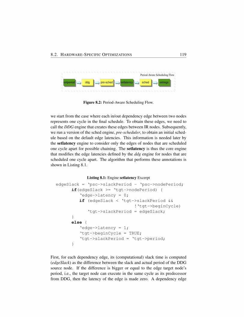
8.2. HARDWARE-SPECIFIC OPTIMIZATIONS 119
Period-Aware Scheduling Flow
ddgddg setlatencysetlatency setregssetregs
Figure 8.2: Period-Aware Scheduling Flow.
we start from the case where each in/out dependency edge between two nodesrepresents one cycle in the final schedule. To obtain these edges, we need tocall the DDG engine that creates these edges between IR nodes. Subsequently,we run a version of the sched engine, pre-scheduler, to obtain an initial sched-ule based on the default edge latencies. This information is needed later bythe setlatency engine to consider only the edges of nodes that are scheduledone cycle apart for possible chaining. The setlatency is thus the core enginethat modifies the edge latencies defined by the ddg engine for nodes that arescheduled one cycle apart. The algorithm that performs these annotations isshown in Listing 8.1.
Listing 8.1: Engine setlatency Excerpt
edgeSlack = ‘psc->slackPeriod - ‘psc->nodePeriod;if(edgeSlack >= ‘tgt->nodePeriod) {
‘edge->latency = 0;if (edgeSlack < ‘tgt->slackPeriod &&
!‘tgt->beginCycle)‘tgt->slackPeriod = edgeSlack;
}else {
‘edge->latency = 1;‘tgt->beginCycle = TRUE;‘tgt->slackPeriod = ‘tgt->period;
}
First, for each dependency edge, its (computational) slack time is computed(edgeSlack) as the difference between the slack and actual period of the DDGsource node. If the difference is bigger or equal to the edge target node’speriod, i.e., the target node can execute in the same cycle as its predecessorfrom DDG, then the latency of the edge is made zero. A dependency edge
120CHAPTER 8. DWARV 3.0: RELEVANT HARDWARE COMPILER
OPTIMIZATIONS
latency of zero implies that the source and target nodes can be scheduled in thesame cycle. Furthermore, if this remaining slack is the smallest between allincoming node predecessor slack periods and this target node was not pushedto the next cycle (i.e., beginCycle is false), its slack period is updated to thisnew value. Otherwise, the latency of the DDG dependency edge is made oneso that the scheduler knows to create a new cycle whenever it needs to schedulethe target node. Finally, the target node is annotated to mark the beginning ofa new cycle and its slack period is reset to the original value.
With this new information annotated on the DDG edges, we can call the sched-uler again to generate the final schedule in which instructions are merged to-gether because their periods can be executed within the global period. The flowis completed with the setregs engine that is used to annotate register variablesin the IR to mark the fact that this virtual register is also a (VHDL) variable be-cause of the cycle merge. Furthermore, those registers that are now used onlyas variables are annotated accordingly so that no register will be generated forthem any more in the final emit phase. Finally, the last modification requiredis to annotate all the rules that generate instructions with a computational classthat represents the maximum time required to complete the computation. Forexample, a shift operation is classified as conversion and will be initializedwith 100 picoseconds. This operation is faster than, for example, an integeraddition that is classified as arithmetic fast. The following list enumerates allthe classes used in DWARV3.0 as well as their allocated computation time. Theinitialization of the mentioned times is done in the setperiod engine.
• conversions: 100 picoseconds
• memory: 1000 picoseconds
• comparison: 1500 picoseconds
• arithmetic fast: 3000 picoseconds
• arithmetic slow: 4000 picoseconds
We note first that these class execution times are now experimental (they arebased on approximations given to various computations extracted from Xilinxdocumentation manuals) and should be further evaluated to allocate more re-alistic execution times. However, the absolute time that such a computationalclass can take depends on multiple factors, such as design density, computa-tional cores and their location relative to the computation or the routing of thedesign. Therefore, deriving more accurate numbers is not trivial and it will
8.2. HARDWARE-SPECIFIC OPTIMIZATIONS 121
be considered in future work. We envision some heuristic model that coulddynamically allocate different node periods based on different situations. Sec-ond, when validating this transformation, we observed that it has a bonus effectby always scheduling register initializations with constants in the same cyclewith the corresponding use of that constant; therefore, allowing the synthesizertool to remove these redundant registers efficiently. This reduces the total area.Finally, as mentioned in the beginning of the section, this transformation al-lows also for the predication to take effect for cases when the if computationdoes not take more than one cycle.
Memory Space Optimization
The previous DWARV implementation was designed on the MOLEN machineorganization which defined one global shared memory from which all func-tion parameters were accessed. This suboptimal design was motivated bythe fact that typical software applications also have only one shared memorywhich contain the application data. Therefore, to support the same computa-tional model, MOLEN was designed to keep these differences to a minimumwhen moving specific kernels to hardware. As a result, the generated kernelhardware had to access its parameters from a similar on FPGA single sharedmemory. However, this is a severe restriction for hardware kernels running onan FPGAs that contain multiple memory modules in the form of distributedBRAMs across the entire area. Therefore, DWARV2.0 was under-performingbecause only one memory operation could be scheduled each cycle. The logi-cal and simple solution to this problem is to use different BRAMs for differentfunction parameters, thus, allowing the scheduling to perform multiple mem-ory operation in one cycle if different parameters are used in that cycle. Thiswould be possible because, in this new case, we would not have a memory con-tention for the same BRAM. This feature is known in the embedded systemsdomain as using different memory spaces.
For this optimization, we assume that a previous running partitioning tool (seeChapter 3) places restrict clauses on parameters. This implies that the seman-tics of the program are not affected by this transformation. Any parameterthat cannot be disambiguated and, therefore, it does not have a restrict clausebefore it, will be placed by default in the generic memory space.
The CoSy framework supports memory spaces through its embedded C99 [47]frontend extension. This allows memory spaces to be defined and used inthe compiler. The code snippet shown in Listing 8.2 illustrates how a simplefunction prototype has been extended to state explicitly that parameter p1 is
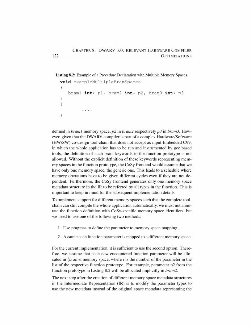
122CHAPTER 8. DWARV 3.0: RELEVANT HARDWARE COMPILER
OPTIMIZATIONS
Listing 8.2: Example of a Procedure Declaration with Multiple Memory Spaces.
void exampleMultipleBramSpaces(
bram1 int* p1, bram2 int* p2, bram3 int* p3){
....}
defined in bram1 memory space, p2 in bram2 respectively p3 in bram3. How-ever, given that the DWARV compiler is part of a complex Hardware/Software(HW/SW) co-design tool-chain that does not accept as input Embedded C99,in which the whole application has to be run and instrumented by gcc basedtools, the definition of such bram keywords in the function prototype is notallowed. Without the explicit definition of these keywords representing mem-ory spaces in the function prototype, the CoSy frontend would assume that wehave only one memory space, the generic one. This leads to a schedule wherememory operations have to be given different cycles even if they are not de-pendent. Furthermore, the CoSy frontend generates only one memory spacemetadata structure in the IR to be referred by all types in the function. This isimportant to keep in mind for the subsequent implementation details.
To implement support for different memory spaces such that the complete tool-chain can still compile the whole application automatically, we must not anno-tate the function definition with CoSy-specific memory space identifiers, butwe need to use one of the following two methods:
1. Use pragmas to define the parameter to memory space mapping.
2. Assume each function parameter is mapped to a different memory space.
For the current implementation, it is sufficient to use the second option. There-fore, we assume that each new encountered function parameter will be allo-cated in 〈bram〉i memory space, where i is the number of the parameter in thelist of the respective function prototype. For example, parameter p2 from thefunction prototype in Listing 8.2 will be allocated implicitly in bram2.
The next step after the creation of different memory space metadata structuresin the Intermediate Representation (IR) is to modify the parameter types touse the new metadata instead of the original space metadata representing the
8.2. HARDWARE-SPECIFIC OPTIMIZATIONS 123
generic memory space. In CoSy, to change the memory space information fora type, we need to clone that type and make its memory space pointer pointto one of the new created memory space metadata. This step is implementedin the hwconfig engine and is essentially a walk over the list of parameters,getting and cloning their type, increasing an iteration index after it is concate-nated into a bram string which is allocated to a newly created space structure’sname. Finally, we associate the space with the new type, and the type withthe parameter. After completing this step, we have each parameter pointing tounique types with a different memory space each.
However, performing this cloning and dissociating the parameters from theoriginal type, we introduce an invalid state in the CoSy IR. That is, parametershave a new type now, whereas the expressions and statements that use theseparameters still point to the old type with the generic memory space. To keepmemory space related modification consistent, we have to propagate these newtypes to all expressions and statements accordingly. This is implemented in anew engine called setmbramtypes. First, to propagate the type to expressionswe perform a depth-first traversal with a pre- and post-action function for eachnode traversed. The CoSy framework offers a specific function for such traver-sals named prepost exprs in proc, which takes as arguments the function toperform the pre-action, a function to perform the post-action and a base param-eter to a structure to keep common information through all calls. Furthermore,we use a stack to remember the expression that has the pointer type on higherlevels. For this one, we need to set the type to the type obtained from the leafparameter node underneath it. This setting is done in the post-action of thetraversal.
Second, to propagate the types also to statements and expressions containinglocals derived from pointer parameters, we need to iterate over all statementsin the procedure as well and look at local definitions and instantiations frompointer parameters. For these pointer type assignments, we copy the type ofthe right hand side to the local on the left leaf side of the assignment tree.We subsequently make a global 〈modified〉 variable true, so that we rememberto iterate once more over all expressions, as well. We need to perform thisaction to propagate these newly allocated real space types to locals up the treeof expressions, as well. We perform these expression and statement traversalsas long as we still have modifications. The final touches are to implementthe disambiguation function to return true for different memory spaces andcreate resources, templates, and dynamic rule function templates for the CoSysched scheduler engine. The disambiguation function is called implicitly bythe default sched engine, whereas the resource, template, and rule function
124CHAPTER 8. DWARV 3.0: RELEVANT HARDWARE COMPILER
OPTIMIZATIONS
templates are used to select the resources which have to be used by each ruleinstance. Because for each memory parameter we define different (memory)resources, the memory disambiguator will report that memory operations withdifferent memory spaces assigned are independent. Therefore, we can nowperform two or more memory operations in parallel.
We mention that the current implementation of CoSy is restrictive from thepoint of view of creating above elements dynamically. In other words, we can-not accommodate on the fly the necessary number of resources and templatesthat are to be associated with the corresponding number of memory spaces.These have to be specified when DWARV is built from sources and have amaximum limit that is defined at compile time (currently set to 60). How-ever, considering the current FPGA implementation and the allocated numberof BRAMs available on them, we believe that this limitation will not restrict inany way the working of the compiler.
8.3 CoSy Compiler Optimizations
In this section, we present one work in progress which is aiming at taking ex-isting software optimizations and customizing them to exploit the hardwarecharacteristics fully. We will do this by restricting ourself to the optimizationsavailable in CoSy in the form of engines. In Chapter 3, we presented all en-gines available in CoSy, and in this section we select only a few for furtherinvestigation. That is, the techniques covered here are loop unrolling, loopinvariant code motion, software-sided caching and algebraic simplifications.Table 8.1 shows how these techniques are divided into CoSy engines and itdescribes briefly what specific task the engine performs. We believe that lever-aging on existing software optimizations and extending or relaxing them forthe hardware compilation process, will allow us to close the performance gapbetween a manually written versus generated HDL code. The goal of this sec-tion is thus to investigate software optimizations from a hardware perspectivein order to be able to understand how these existing optimizations could be ap-plied for the hardware generation process. The inherent benefit is to possiblyleverage on the large amount of previous research done for software compilers.In this sense, work has been started which concluded in a master thesis [75].The discoveries are briefly summarized in this section.
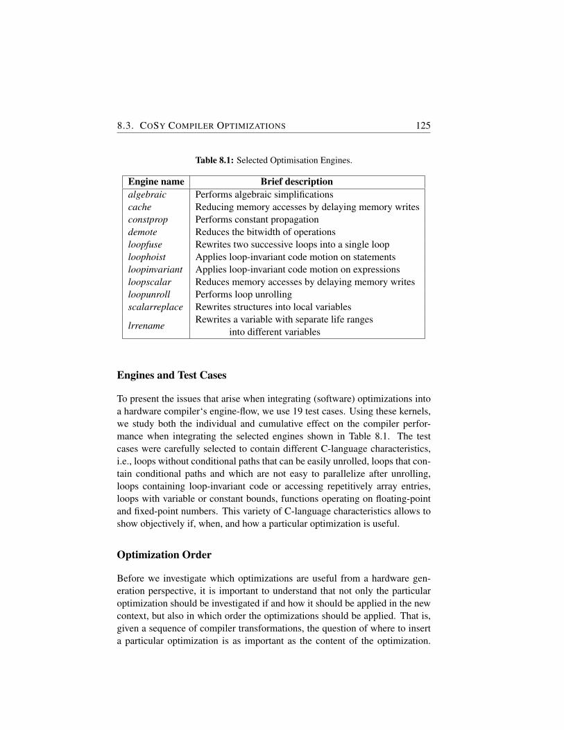
8.3. COSY COMPILER OPTIMIZATIONS 125
Table 8.1: Selected Optimisation Engines.
Engine name Brief descriptionalgebraic Performs algebraic simplificationscache Reducing memory accesses by delaying memory writesconstprop Performs constant propagationdemote Reduces the bitwidth of operationsloopfuse Rewrites two successive loops into a single looploophoist Applies loop-invariant code motion on statementsloopinvariant Applies loop-invariant code motion on expressionsloopscalar Reduces memory accesses by delaying memory writesloopunroll Performs loop unrollingscalarreplace Rewrites structures into local variables
lrrenameRewrites a variable with separate life ranges
into different variables
Engines and Test Cases
To present the issues that arise when integrating (software) optimizations intoa hardware compiler‘s engine-flow, we use 19 test cases. Using these kernels,we study both the individual and cumulative effect on the compiler perfor-mance when integrating the selected engines shown in Table 8.1. The testcases were carefully selected to contain different C-language characteristics,i.e., loops without conditional paths that can be easily unrolled, loops that con-tain conditional paths and which are not easy to parallelize after unrolling,loops containing loop-invariant code or accessing repetitively array entries,loops with variable or constant bounds, functions operating on floating-pointand fixed-point numbers. This variety of C-language characteristics allows toshow objectively if, when, and how a particular optimization is useful.
Optimization Order
Before we investigate which optimizations are useful from a hardware gen-eration perspective, it is important to understand that not only the particularoptimization should be investigated if and how it should be applied in the newcontext, but also in which order the optimizations should be applied. That is,given a sequence of compiler transformations, the question of where to inserta particular optimization is as important as the content of the optimization.
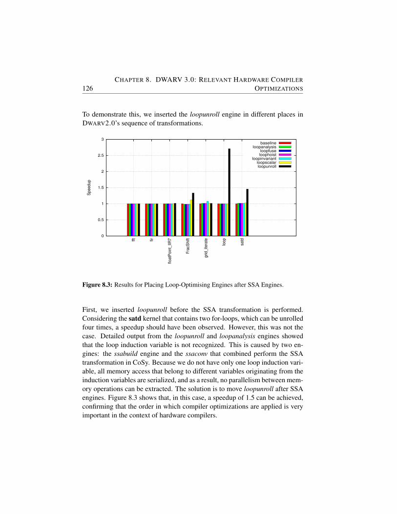
126CHAPTER 8. DWARV 3.0: RELEVANT HARDWARE COMPILER
OPTIMIZATIONS
To demonstrate this, we inserted the loopunroll engine in different places inDWARV2.0’s sequence of transformations.
0
0.5
1
1.5
2
2.5
3
fft
fir
floa
tPo
int_
IIR
7
Fra
cSh
ift
grid
_ite
rate
loo
p
satd
Sp
ee
du
p
baselineloopanalysis
loopfuseloophoist
loopinvariantloopscalarloopunroll
Figure 8.3: Results for Placing Loop-Optimising Engines after SSA Engines.
First, we inserted loopunroll before the SSA transformation is performed.Considering the satd kernel that contains two for-loops, which can be unrolledfour times, a speedup should have been observed. However, this was not thecase. Detailed output from the loopunroll and loopanalysis engines showedthat the loop induction variable is not recognized. This is caused by two en-gines: the ssabuild engine and the ssaconv that combined perform the SSAtransformation in CoSy. Because we do not have only one loop induction vari-able, all memory access that belong to different variables originating from theinduction variables are serialized, and as a result, no parallelism between mem-ory operations can be extracted. The solution is to move loopunroll after SSAengines. Figure 8.3 shows that, in this case, a speedup of 1.5 can be achieved,confirming that the order in which compiler optimizations are applied is veryimportant in the context of hardware compilers.
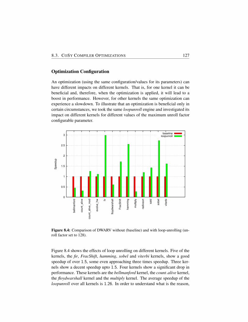
8.3. COSY COMPILER OPTIMIZATIONS 127
Optimization Configuration
An optimization (using the same configuration/values for its parameters) canhave different impacts on different kernels. That is, for one kernel it can bebeneficial and, therefore, when the optimization is applied, it will lead to aboost in performance. However, for other kernels the same optimization canexperience a slowdown. To illustrate that an optimization is beneficial only incertain circumstances, we took the same loopunroll engine and investigated itsimpact on different kernels for different values of the maximum unroll factorconfigurable parameter.
0
0.5
1
1.5
2
2.5
3
be
llma
nfo
rd
co
un
t_a
live
co
un
t_a
live
_m
od
evo
lve
_h
w fir
flo
yd
wa
rsh
all
Fra
cS
hift
ha
mm
ing
mu
ltip
ly
rad
ixso
rt
sa
td
so
be
l
vite
rbi
Sp
ee
du
p
baselineloopunroll
Figure 8.4: Comparison of DWARV without (baseline) and with loop-unrolling (un-roll factor set to 128).
Figure 8.4 shows the effects of loop unrolling on different kernels. Five of thekernels, the fir, FracShift, hamming, sobel and viterbi kernels, show a goodspeedup of over 1.5, some even approaching three times speedup. Three ker-nels show a decent speedup upto 1.5. Four kernels show a significant drop inperformance. These kernels are the bellmanford kernel, the count alive kernel,the floydwarshall kernel and the multiply kernel. The average speedup of theloopunroll over all kernels is 1.26. In order to understand what is the reason,
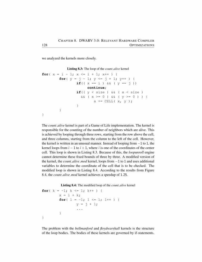
128CHAPTER 8. DWARV 3.0: RELEVANT HARDWARE COMPILER
OPTIMIZATIONS
we analyzed the kernels more closely.
Listing 8.3: The loop of the count alive kernel
for( x = i - 1; x <= i + 1; x++ ) {for( y = j - 1; y <= j + 1; y++ ) {
if(( x == i ) && ( y == j ))continue;
if(( y < size ) && ( x < size )&& ( x >= 0 ) && ( y >= 0 ) ) {
a += CELL( x, y );}
}}
The count alive kernel is part of a Game of Life implementation. The kernel isresponsible for the counting of the number of neighbors which are alive. Thisis achieved by looping through three rows, starting from the row above the cell,and three columns, starting from the column to the left of the cell. However,the kernel is written in an unusual manner. Instead of looping from−1 to 1, thekernel loops from i − 1 to i +1, where i is one of the coordinates of the centercell. This loop is shown in Listing 8.3. Because of this, the loopunroll enginecannot determine these fixed bounds of three by three. A modified version ofthe kernel, the count alive mod kernel, loops from−1 to 1 and uses additionalvariables to determine the coordinate of the cell that is to be checked. Themodified loop is shown in Listing 8.4. According to the results from Figure8.4, the count alive mod kernel achieves a speedup of 1.25.
Listing 8.4: The modified loop of the count alive kernel
for( k = -1; k <= 1; k++ ) {x = i + k;for( l = -1; l <= 1; l++ ) {
y = j + l;...
}}
The problem with the bellmanford and floydwarshall kernels is the structureof the loop bodies. The bodies of these kernels are governed by if-statements.
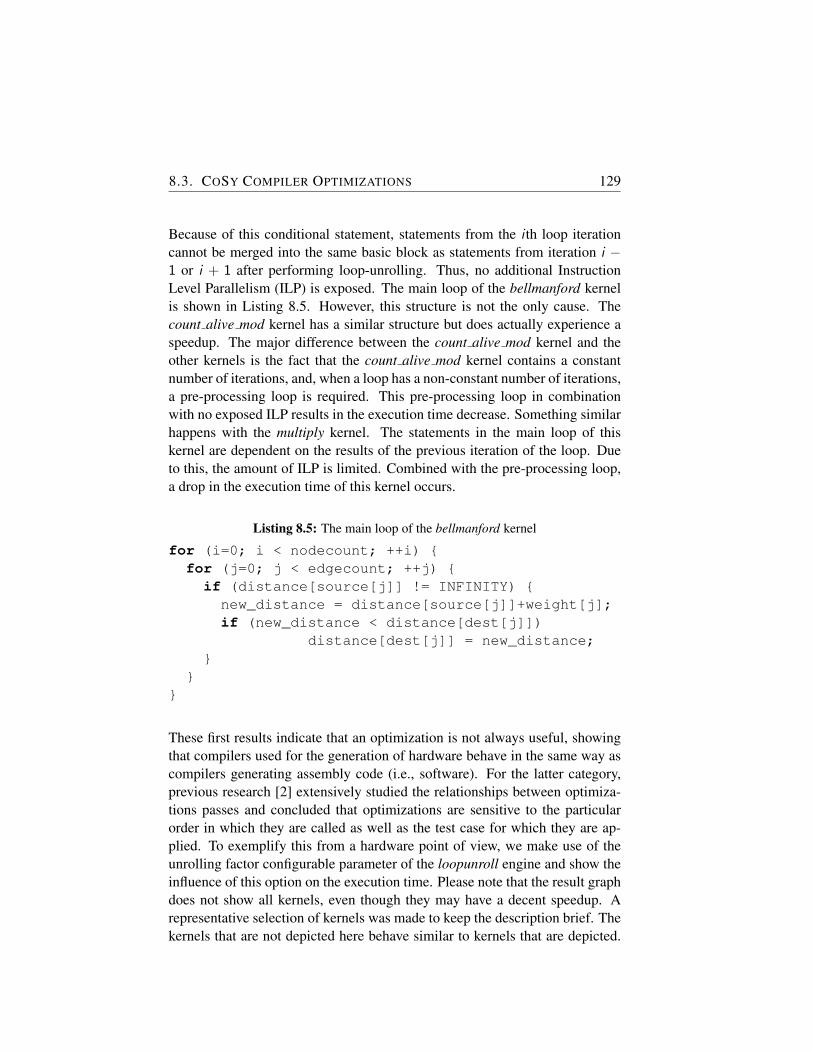
8.3. COSY COMPILER OPTIMIZATIONS 129
Because of this conditional statement, statements from the i th loop iterationcannot be merged into the same basic block as statements from iteration i −1 or i + 1 after performing loop-unrolling. Thus, no additional InstructionLevel Parallelism (ILP) is exposed. The main loop of the bellmanford kernelis shown in Listing 8.5. However, this structure is not the only cause. Thecount alive mod kernel has a similar structure but does actually experience aspeedup. The major difference between the count alive mod kernel and theother kernels is the fact that the count alive mod kernel contains a constantnumber of iterations, and, when a loop has a non-constant number of iterations,a pre-processing loop is required. This pre-processing loop in combinationwith no exposed ILP results in the execution time decrease. Something similarhappens with the multiply kernel. The statements in the main loop of thiskernel are dependent on the results of the previous iteration of the loop. Dueto this, the amount of ILP is limited. Combined with the pre-processing loop,a drop in the execution time of this kernel occurs.
Listing 8.5: The main loop of the bellmanford kernel
for (i=0; i < nodecount; ++i) {for (j=0; j < edgecount; ++j) {
if (distance[source[j]] != INFINITY) {new_distance = distance[source[j]]+weight[j];if (new_distance < distance[dest[j]])
distance[dest[j]] = new_distance;}
}}
These first results indicate that an optimization is not always useful, showingthat compilers used for the generation of hardware behave in the same way ascompilers generating assembly code (i.e., software). For the latter category,previous research [2] extensively studied the relationships between optimiza-tions passes and concluded that optimizations are sensitive to the particularorder in which they are called as well as the test case for which they are ap-plied. To exemplify this from a hardware point of view, we make use of theunrolling factor configurable parameter of the loopunroll engine and show theinfluence of this option on the execution time. Please note that the result graphdoes not show all kernels, even though they may have a decent speedup. Arepresentative selection of kernels was made to keep the description brief. Thekernels that are not depicted here behave similar to kernels that are depicted.
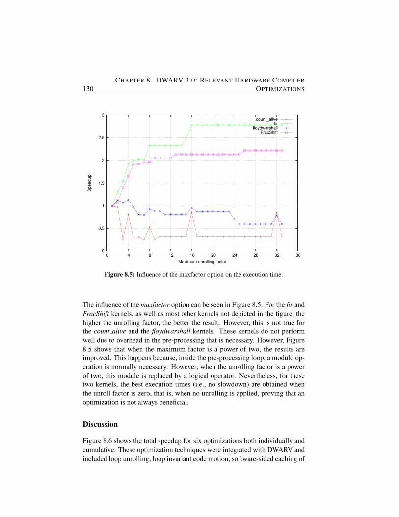
130CHAPTER 8. DWARV 3.0: RELEVANT HARDWARE COMPILER
OPTIMIZATIONS
0
0.5
1
1.5
2
2.5
3
0 4 8 12 16 20 24 28 32 36
Sp
ee
du
p
Maximum unrolling factor
count_alivefir
floydwarshallFracShift
Figure 8.5: Influence of the maxfactor option on the execution time.
The influence of the maxfactor option can be seen in Figure 8.5. For the fir andFracShift kernels, as well as most other kernels not depicted in the figure, thehigher the unrolling factor, the better the result. However, this is not true forthe count alive and the floydwarshall kernels. These kernels do not performwell due to overhead in the pre-processing that is necessary. However, Figure8.5 shows that when the maximum factor is a power of two, the results areimproved. This happens because, inside the pre-processing loop, a modulo op-eration is normally necessary. However, when the unrolling factor is a powerof two, this module is replaced by a logical operator. Nevertheless, for thesetwo kernels, the best execution times (i.e., no slowdown) are obtained whenthe unroll factor is zero, that is, when no unrolling is applied, proving that anoptimization is not always beneficial.
Discussion
Figure 8.6 shows the total speedup for six optimizations both individually andcumulative. These optimization techniques were integrated with DWARV andincluded loop unrolling, loop invariant code motion, software-sided caching of
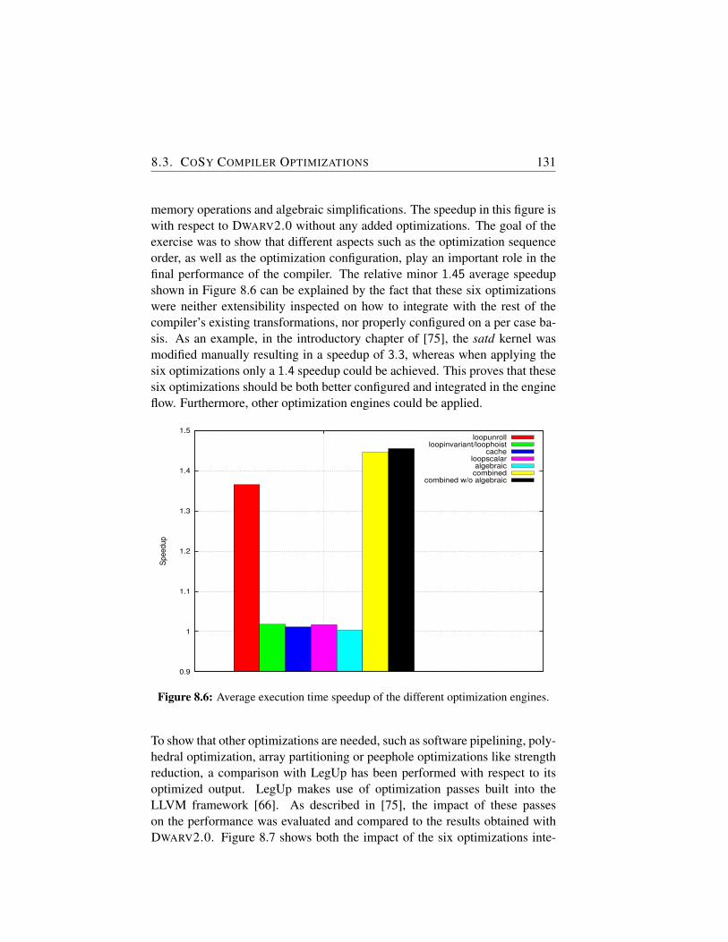
8.3. COSY COMPILER OPTIMIZATIONS 131
memory operations and algebraic simplifications. The speedup in this figure iswith respect to DWARV2.0 without any added optimizations. The goal of theexercise was to show that different aspects such as the optimization sequenceorder, as well as the optimization configuration, play an important role in thefinal performance of the compiler. The relative minor 1.45 average speedupshown in Figure 8.6 can be explained by the fact that these six optimizationswere neither extensibility inspected on how to integrate with the rest of thecompiler’s existing transformations, nor properly configured on a per case ba-sis. As an example, in the introductory chapter of [75], the satd kernel wasmodified manually resulting in a speedup of 3.3, whereas when applying thesix optimizations only a 1.4 speedup could be achieved. This proves that thesesix optimizations should be both better configured and integrated in the engineflow. Furthermore, other optimization engines could be applied.
0.9
1
1.1
1.2
1.3
1.4
1.5
Sp
ee
du
p
loopunrollloopinvariant/loophoist
cacheloopscalaralgebraic
combinedcombined w/o algebraic
Figure 8.6: Average execution time speedup of the different optimization engines.
To show that other optimizations are needed, such as software pipelining, poly-hedral optimization, array partitioning or peephole optimizations like strengthreduction, a comparison with LegUp has been performed with respect to itsoptimized output. LegUp makes use of optimization passes built into theLLVM framework [66]. As described in [75], the impact of these passeson the performance was evaluated and compared to the results obtained withDWARV2.0. Figure 8.7 shows both the impact of the six optimizations inte-
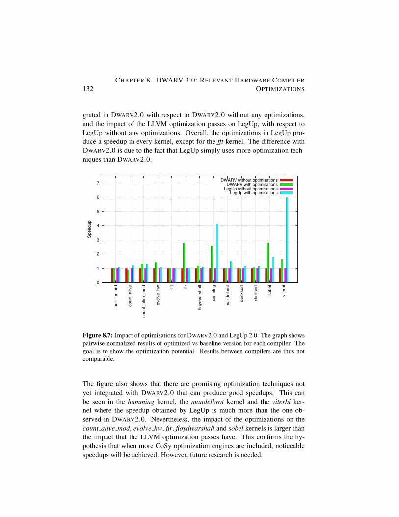
132CHAPTER 8. DWARV 3.0: RELEVANT HARDWARE COMPILER
OPTIMIZATIONS
grated in DWARV2.0 with respect to DWARV2.0 without any optimizations,and the impact of the LLVM optimization passes on LegUp, with respect toLegUp without any optimizations. Overall, the optimizations in LegUp pro-duce a speedup in every kernel, except for the fft kernel. The difference withDWARV2.0 is due to the fact that LegUp simply uses more optimization tech-niques than DWARV2.0.
0
1
2
3
4
5
6
7
be
llma
nfo
rd
co
un
t_a
live
co
un
t_a
live
_m
od
evo
lve
_h
w fft
fir
flo
yd
wa
rsh
all
ha
mm
ing
ma
nd
elb
rot
qu
ickso
rt
sh
ells
ort
so
be
l
vite
rbi
Sp
ee
du
p
DWARV without optimisationsDWARV with optimisations
LegUp without optimisationsLegUp with optimisations
Figure 8.7: Impact of optimisations for DWARV2.0 and LegUp 2.0. The graph showspairwise normalized results of optimized vs baseline version for each compiler. Thegoal is to show the optimization potential. Results between compilers are thus notcomparable.
The figure also shows that there are promising optimization techniques notyet integrated with DWARV2.0 that can produce good speedups. This canbe seen in the hamming kernel, the mandelbrot kernel and the viterbi ker-nel where the speedup obtained by LegUp is much more than the one ob-served in DWARV2.0. Nevertheless, the impact of the optimizations on thecount alive mod, evolve hw, fir, floydwarshall and sobel kernels is larger thanthe impact that the LLVM optimization passes have. This confirms the hy-pothesis that when more CoSy optimization engines are included, noticeablespeedups will be achieved. However, future research is needed.
8.4. CONCLUSIONS 133
One of the research directions is to study how an optimization parameter hasto be configured on a per case basis. More concretely, an optimization hasdifferent parameters that can be tweaked, such as loop unroll maximum factoror the number of nested loop levels that will be unrolled. To obtain a goodspeedup, simply including a software optimization with its parameters set todefault values is not sufficient. One would need to provide sensible values forthese parameters on a per case basis to obtain good results. Furthermore, weneed not only to change the configurations of the different optimizations, butwe need also to include/exclude or change the optimizations sequence based ona per case basis. Anything less than that will not give optimal results as it wasshown in this section. Future work will analyze what strategies are necessaryto devise algorithms able to decide automatically when and how to include aparticular optimization in a hardware compiler.
One final remark is needed to acknowledge the software pipelining optimiza-tion as one of the most promising to integrate in DWARV3.0. According todiscussions with Hans van Sommeren from ACE bv. and Stephen Neuendorf-fer from Xilinx Research Labs, this optimization has potential of speeding upkernels by a few orders of magnitude. The CoSy framework has the advan-tage of supporting the software pipelining optimization in the form of a setof standard engines that can be included in any compiler. To test the bene-fit of this powerful optimization for hardware designs, we simply plugged thesoftware pipelining related engines in DWARV3.0. The implementation wasstraightforward, and it was done by following the CoSy documentation thatgives precise step-by-step instructions about what engine to include in the en-gine flow. However, the experiments performed on simple tests revealed thatthis optimization is rarely enabled. This is mostly caused by the vast amountof configurable options that need to be fine-tuned to make this optimizationfully functional. Given the time limit, we leave the proper configuration andperformance analysis of the software pipelining optimization as future work.
8.4 Conclusions
In this chapter, we presented a few hardware relevant techniques intended toimprove the performance of the unoptimized DWARV2.0 hardware compiler.We argued that and described how supporting predicated execution, chainingoperations and using multiple memory spaces reduces this performance gap.Results for the new DWARV3.0 compiler that includes these optimizations willbe presented in the next chapter. Finally, section 8.3 showed that there is room
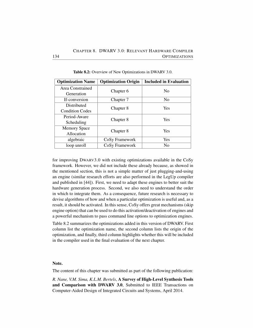
134CHAPTER 8. DWARV 3.0: RELEVANT HARDWARE COMPILER
OPTIMIZATIONS
Table 8.2: Overview of New Optimizations in DWARV 3.0.
Optimization Name Optimization Origin Included in EvaluationArea Constrained
Chapter 6 NoGeneration
If-conversion Chapter 7 NoDistributed
Chapter 8 YesCondition Codes
Period-AwareChapter 8 Yes
SchedulingMemory Space
Chapter 8 YesAllocationalgebraic CoSy Framework Yes
loop unroll CoSy Framework No
for improving DWARV3.0 with existing optimizations available in the CoSyframework. However, we did not include these already because, as showed inthe mentioned section, this is not a simple matter of just plugging-and-usingan engine (similar research efforts are also performed in the LegUp compilerand published in [44]). First, we need to adapt these engines to better suit thehardware generation process. Second, we also need to understand the orderin which to integrate them. As a consequence, future research is necessary todevise algorithms of how and when a particular optimization is useful and, as aresult, it should be activated. In this sense, CoSy offers great mechanisms (skipengine option) that can be used to do this activation/deactivation of engines anda powerful mechanism to pass command line options to optimization engines.
Table 8.2 summarizes the optimizations added in this version of DWARV. Firstcolumn list the optimization name, the second column lists the origin of theoptimization, and finally, third column highlights whether this will be includedin the compiler used in the final evaluation of the next chapter.
Note.
The content of this chapter was submitted as part of the following publication:
R. Nane, V.M. Sima, K.L.M. Bertels, A Survey of High-Level Synthesis Toolsand Comparison with DWARV 3.0, Submitted to IEEE Transactions onComputer-Aided Design of Integrated Circuits and Systems, April 2014.
9Hardware Compilers Evaluation
IN this chapter we evaluate state-of-the-art High-Level Synthesis (HLS)tools by investigating their performance with respect to a number of pre-defined performance criteria. After formally introducing the goal of this
chapter, we present in Section 9.2 the four selection criteria we require to in-clude a tool in the comparison. Subsequent section describes the tools selected.Sections 9.4 and 9.5 present software and hardware metrics for both the bench-mark functions used in the comparison as well as for the generated hardwarekernels, respectively. The comparison results are shown in Section 9.6 whilethe last section draws the conclusions of the evaluation.
9.1 Introduction
To obtain the most realistic state-of-the-art quantification, we need to evaluateas many compilers as possible. The related work section presented an abundantnumber of available hardware compilers. Because the number of compilersavailable today both in the industry and academia is not small, coupled withthe fact that not all tools from industry offer an evaluation license, we couldnot include all compilers in the evaluation. From the list of tools presented inChapter 2, we investigated approximately half of them. However, after a closerinvestigation, we decided to exclude some of them because they did not fulfilall the selection criteria (i.e., the tool output is not comparable to DWARV3.0)defined in the next section. We will briefly describe in Section 9.3 what werethe specific issues that led to the decision of not including a particular tool intothe final comparison. However, before reasoning about this tool selection, weneed first to describe the specific selection criteria.
135
136 CHAPTER 9. HARDWARE COMPILERS EVALUATION
9.2 Tool Selection Criteria
We number the criteria with (1), (2), (3) and (4) respectively, for ease of refer-ence in the next section:
1. The first and most important requirement to include a tool in the com-parison was to generate accelerators that are able to connect with ashared memory via their generated interface. The reason is that wewant to focus on tools that are closely related to the design princi-ples of DWARV3.0, and, therefore, allow us to compare and eval-uate their performance against that of DWARV3.0. Figure 9.1 de-picts the minimum requirements for the generated accelerator’s inter-face graphically. Signals such as set data address Xi, get data value Xi,write data value Xi, write enable Xi should be part of the interface toallow values for parameter named Xi to be read/written from/to theshared memory. This requirement is directly derived from one of theassumptions in DWARV3.0, namely from the MOLEN context where itsgenerated accelerators are integrated. Although derived from MOLEN,this requirement is generic for any shared/distributed type of system.Other signals necessary for synchronization are reset, clock, start anddone of the accelerator.
2. The second criterion concerns the availability and completeness of tooldocumentation, if it is still maintained, the time required to learn how touse it and the time required to adapt the benchmark kernels to syntax ac-cepted by the compiler. This implies that compilers requiring a modifiedor extended subset of the C language will fail this criterion because it istime consuming to learn the necessary language extension to rewrite thebenchmark kernels to a form accepted by the tool.
3. The third criterion concerns the availability of a free evaluation or aca-demic license. When this was not the case, no further action was takento include it in the evaluation.
4. The fourth and final criterion requires that the tool in question can gen-erate a test bench. This is needed not only to test the correctness of thegenerated hardware, but also to run simulations to obtain actual simula-tion cycle counts based on a particular input data set.
Before we start describing the tools and present the results, it is worth notingthat, for the various tools, there are different optimizations and features avail-
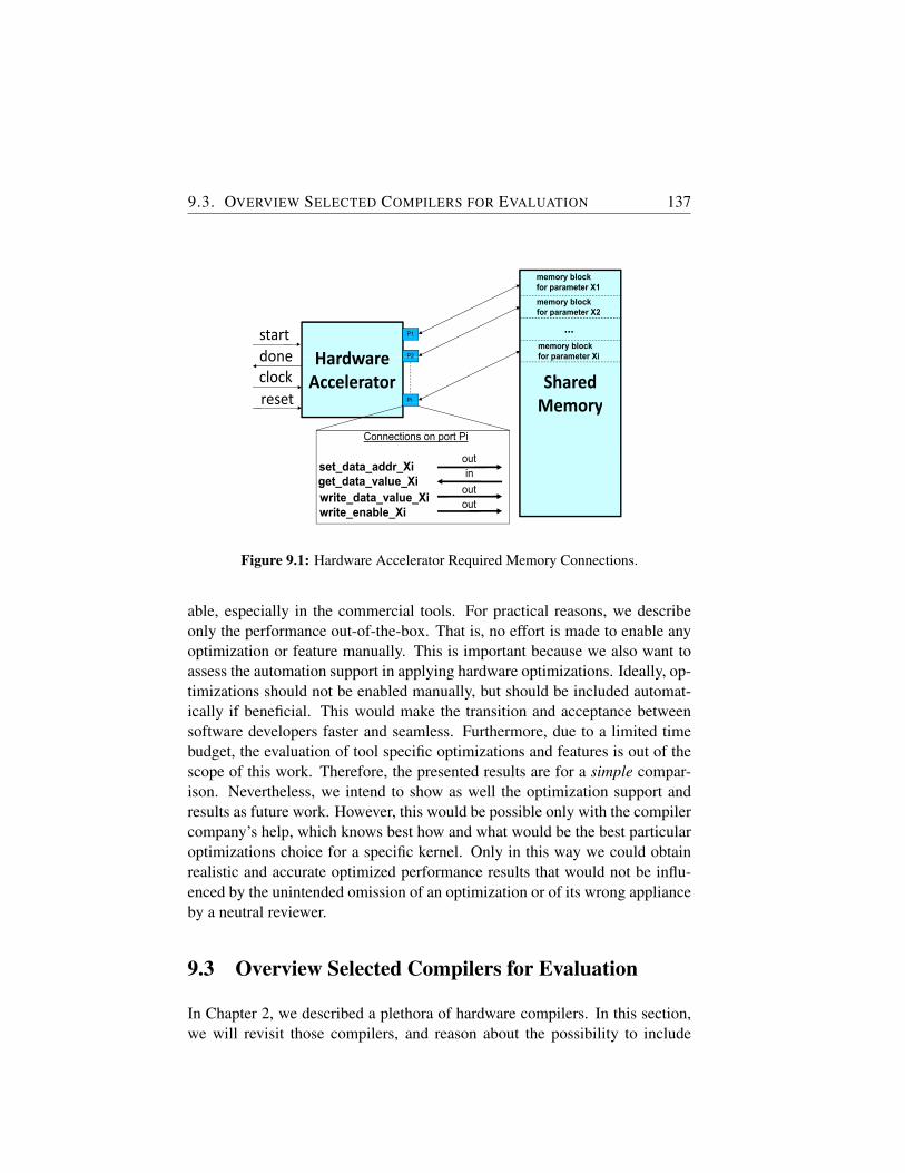
9.3. OVERVIEW SELECTED COMPILERS FOR EVALUATION 137
Hardwarestartdone
P1
P2HardwareAccelerator
done
resetclock
P2
Pireset
Connections on po
set_data_addr_Xiget_data_value_Xi
it d t l Xiwrite_data_value_Xiwrite_enable_Xi
memory block for parameter X1memory block for parameter X2
...for parameter X2
memory block for parameter Xi
SharedMemory
for parameter Xi
Memory
ort Pi
out
outin
out
Figure 9.1: Hardware Accelerator Required Memory Connections.
able, especially in the commercial tools. For practical reasons, we describeonly the performance out-of-the-box. That is, no effort is made to enable anyoptimization or feature manually. This is important because we also want toassess the automation support in applying hardware optimizations. Ideally, op-timizations should not be enabled manually, but should be included automat-ically if beneficial. This would make the transition and acceptance betweensoftware developers faster and seamless. Furthermore, due to a limited timebudget, the evaluation of tool specific optimizations and features is out of thescope of this work. Therefore, the presented results are for a simple compar-ison. Nevertheless, we intend to show as well the optimization support andresults as future work. However, this would be possible only with the compilercompany’s help, which knows best how and what would be the best particularoptimizations choice for a specific kernel. Only in this way we could obtainrealistic and accurate optimized performance results that would not be influ-enced by the unintended omission of an optimization or of its wrong applianceby a neutral reviewer.
9.3 Overview Selected Compilers for Evaluation
In Chapter 2, we described a plethora of hardware compilers. In this section,we will revisit those compilers, and reason about the possibility to include
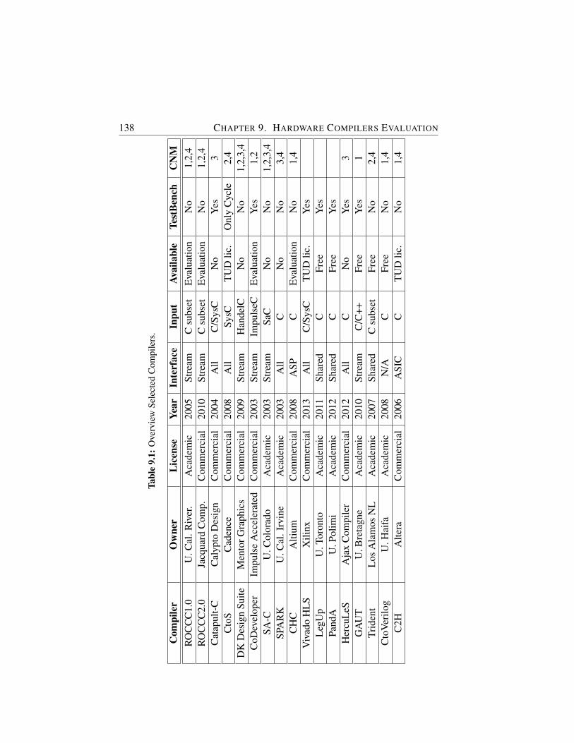
138 CHAPTER 9. HARDWARE COMPILERS EVALUATION
Tabl
e9.
1:O
verv
iew
Sele
cted
Com
pile
rs.
Com
pile
rO
wne
rL
icen
seYe
arIn
terf
ace
Inpu
tAv
aila
ble
Test
Ben
chC
NM
RO
CC
C1.
0U
.Cal
.Riv
er.
Aca
dem
ic20
05St
ream
Csu
bset
Eva
luat
ion
No
1,2,
4R
OC
CC
2.0
Jacq
uard
Com
p.C
omm
erci
al20
10St
ream
Csu
bset
Eva
luat
ion
No
1,2,
4C
atap
ult-
CC
alyp
toD
esig
nC
omm
erci
al20
04A
llC
/Sys
CN
oY
es3
Cto
SC
aden
ceC
omm
erci
al20
08A
llSy
sCT
UD
lic.
Onl
yC
ycle
2,4
DK
Des
ign
Suite
Men
torG
raph
ics
Com
mer
cial
2009
Stre
amH
ande
lCN
oN
o1,
2,3,
4C
oDev
elop
erIm
puls
eA
ccel
erat
edC
omm
erci
al20
03St
ream
Impu
lseC
Eva
luat
ion
Yes
1,2
SA-C
U.C
olor
ado
Aca
dem
ic20
03St
ream
SaC
No
No
1,2,
3,4
SPA
RK
U.C
al.I
rvin
eA
cade
mic
2003
All
CN
oN
o3,
4C
HC
Alti
umC
omm
erci
al20
08A
SPC
Eva
luat
ion
No
1,4
Viv
ado
HL
SX
ilinx
Com
mer
cial
2013
All
C/S
ysC
TU
Dlic
.Y
esL
egU
pU
.Tor
onto
Aca
dem
ic20
11Sh
ared
CFr
eeY
esPa
ndA
U.P
olim
iA
cade
mic
2012
Shar
edC
Free
Yes
Her
cuL
eSA
jax
Com
pile
rC
omm
erci
al20
12A
llC
No
Yes
3G
AU
TU
.Bre
tagn
eA
cade
mic
2010
Stre
amC
/C++
Free
Yes
1Tr
iden
tL
osA
lam
osN
LA
cade
mic
2007
Shar
edC
subs
etFr
eeN
o2,
4C
toV
erilo
gU
.Hai
faA
cade
mic
2008
N/A
CFr
eeN
o1,
4C
2HA
ltera
Com
mer
cial
2006
ASI
CC
TU
Dlic
.N
o1,
4
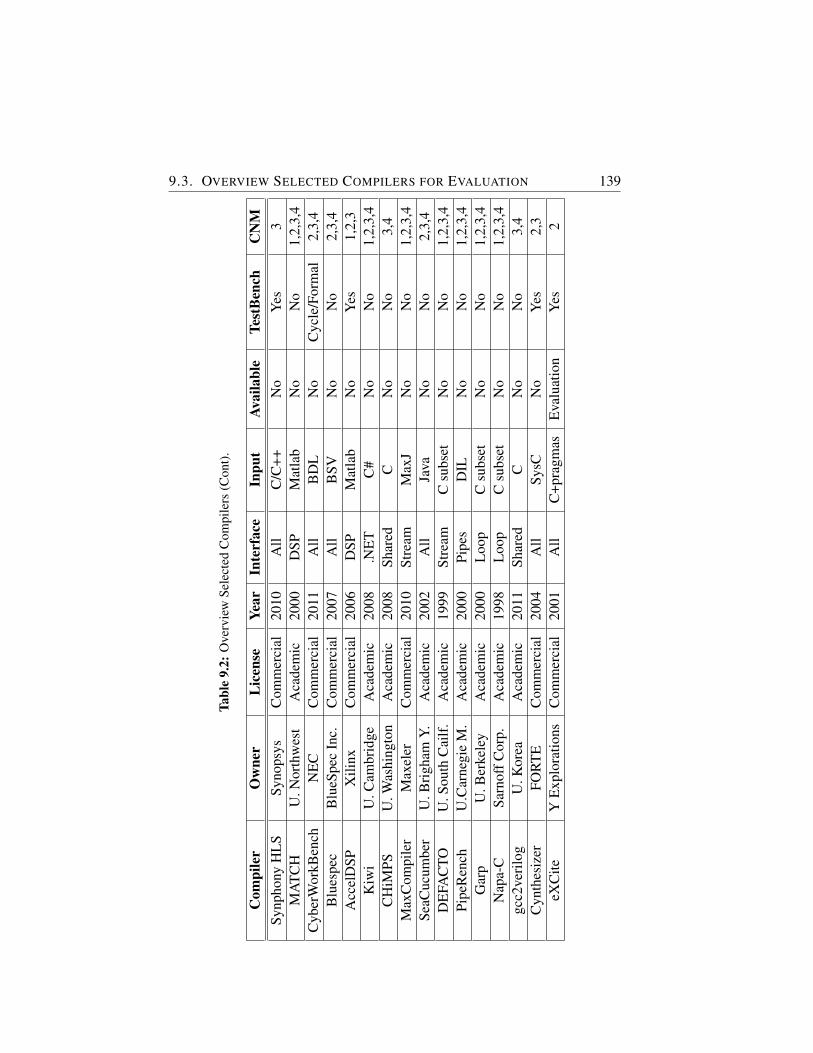
9.3. OVERVIEW SELECTED COMPILERS FOR EVALUATION 139
Tabl
e9.
2:O
verv
iew
Sele
cted
Com
pile
rs(C
ont)
.
Com
pile
rO
wne
rL
icen
seYe
arIn
terf
ace
Inpu
tAv
aila
ble
Test
Ben
chC
NM
Synp
hony
HL
SSy
nops
ysC
omm
erci
al20
10A
llC
/C++
No
Yes
3M
AT
CH
U.N
orth
wes
tA
cade
mic
2000
DSP
Mat
lab
No
No
1,2,
3,4
Cyb
erW
orkB
ench
NE
CC
omm
erci
al20
11A
llB
DL
No
Cyc
le/F
orm
al2,
3,4
Blu
espe
cB
lueS
pec
Inc.
Com
mer
cial
2007
All
BSV
No
No
2,3,
4A
ccel
DSP
Xili
nxC
omm
erci
al20
06D
SPM
atla
bN
oY
es1,
2,3
Kiw
iU
.Cam
brid
geA
cade
mic
2008
.NE
TC
#N
oN
o1,
2,3,
4C
HiM
PSU
.Was
hing
ton
Aca
dem
ic20
08Sh
ared
CN
oN
o3,
4M
axC
ompi
ler
Max
eler
Com
mer
cial
2010
Stre
amM
axJ
No
No
1,2,
3,4
SeaC
ucum
ber
U.B
righ
amY.
Aca
dem
ic20
02A
llJa
vaN
oN
o2,
3,4
DE
FAC
TOU
.Sou
thC
ailf
.A
cade
mic
1999
Stre
amC
subs
etN
oN
o1,
2,3,
4Pi
peR
ench
U.C
arne
gie
M.
Aca
dem
ic20
00Pi
pes
DIL
No
No
1,2,
3,4
Gar
pU
.Ber
kele
yA
cade
mic
2000
Loo
pC
subs
etN
oN
o1,
2,3,
4N
apa-
CSa
rnof
fCor
p.A
cade
mic
1998
Loo
pC
subs
etN
oN
o1,
2,3,
4gc
c2ve
rilo
gU
.Kor
eaA
cade
mic
2011
Shar
edC
No
No
3,4
Cyn
thes
izer
FOR
TE
Com
mer
cial
2004
All
SysC
No
Yes
2,3
eXC
iteY
Exp
lora
tions
Com
mer
cial
2001
All
C+p
ragm
asE
valu
atio
nY
es2
140 CHAPTER 9. HARDWARE COMPILERS EVALUATION
them in the final evaluation. To present the selection in a compact way, wemake use of Tables 9.1 and 9.2. These tables show in the first four columns thename of the tool, who distributes it , under what type of license it is availableand since what year. The fifth column highlights what type of interface the toolcan generate, i.e., streaming, shared, or both, while the sixth column lists howthe tool input should be specified. The next two columns indicate if the toolcan generate test benches and whether the tool is available for download. Ifthe latter is true, this column will specify if it is freely available (or if TU Delfthad a license already for it or if it is available under an evaluation license).Finally, the Criteria Not Met (CNM) column, shows which of the four abovementioned criteria are not met by the tool, and, therefore, will not be includedin the tool comparison. By negation, a tool is included in the comparison onlywhen this column is empty, that is, all criteria were fulfilled.
Tables 9.1 and 9.2 show thus that it is impossible to obtain results for all thetools given in the related work chapter (Chapter 2). As a result, in the subse-quent we will focus on tools intended for multiple domains and that are ableto generate shared memory interface based accelerators. Although some of thetools can support different types of interfaces, to make results comparable, weonly look at this particular interface. This is because we want to quantify theperformance of DWARV3.0 at the same time as well, and as this supports onlythe shared memory interface, we restrict ourselves only to similar tools.
9.4 Benchmark Overview
The test bench used for the evaluation is composed of 11 carefully selectedkernels from six different application domains. Although, CHSTONE is be-coming the test bench used for benchmarking HLS tools, we didn’t use it en-tirely because of two reasons. First, we wanted to be objective and evaluatecompilers that were not particularly designed to give good performance onlyfor kernels in this test suite. Therefore, we selected kernels from the examplesdirectory found in the releases of different tools, in particular we used kernelsfrom Vivado HLS, DWARV and LegUp. Please note that LegUp supports theCHSTONE benchmark, therefore, the kernels selected from its test bench areactually kernels originating from CHSTONE. However, these have been man-ually changed to transform global parameters to function parameters to enableDWARV compilation. The second reason for not using CHSTONE entirely,is thus that DWARV is not supporting global parameters, and the CHSTONEkernels not selected make heavily use of these variables. As DWARV will sup-
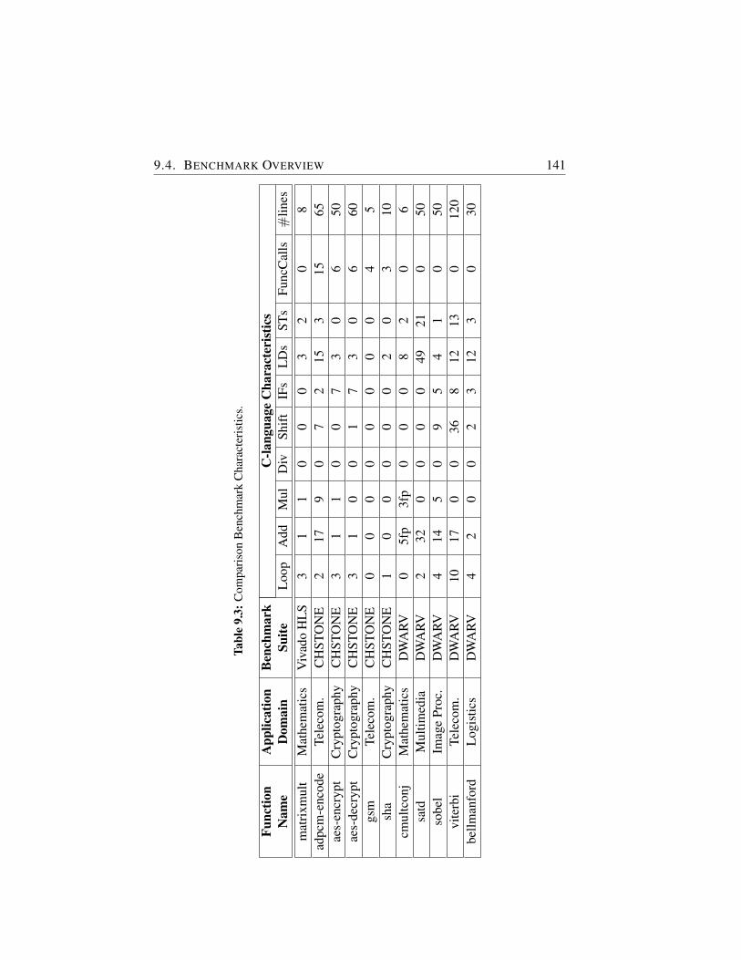
9.4. BENCHMARK OVERVIEW 141
Tabl
e9.
3:C
ompa
riso
nB
ench
mar
kC
hara
cter
istic
s.
Func
tion
App
licat
ion
Ben
chm
ark
C-la
ngua
geC
hara
cter
istic
sN
ame
Dom
ain
Suite
Loo
pA
ddM
ulD
ivSh
ift
IFs
LD
sST
sFu
ncC
alls
#lin
esm
atri
xmul
tM
athe
mat
ics
Viv
ado
HL
S3
11
00
03
20
8ad
pcm
-enc
ode
Tele
com
.C
HST
ON
E2
179
07
215
315
65ae
s-en
cryp
tC
rypt
ogra
phy
CH
STO
NE
31
10
07
30
650
aes-
decr
ypt
Cry
ptog
raph
yC
HST
ON
E3
10
01
73
06
60gs
mTe
leco
m.
CH
STO
NE
00
00
00
00
45
sha
Cry
ptog
raph
yC
HST
ON
E1
00
00
02
03
10cm
ultc
onj
Mat
hem
atic
sD
WA
RV0
5fp
3fp
00
08
20
6sa
tdM
ultim
edia
DW
ARV
232
00
00
4921
050
sobe
lIm
age
Proc
.D
WA
RV4
145
09
54
10
50vi
terb
iTe
leco
m.
DW
ARV
1017
00
368
1213
012
0be
llman
ford
Log
istic
sD
WA
RV4
20
02
312
30
30
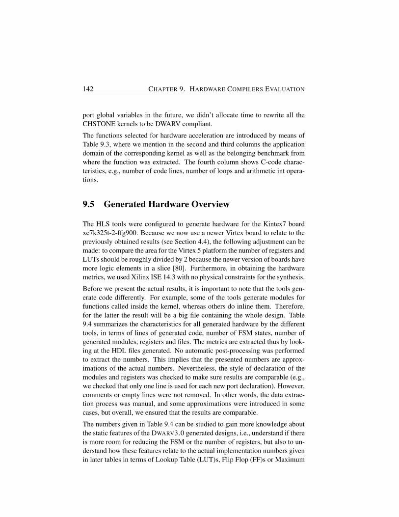
142 CHAPTER 9. HARDWARE COMPILERS EVALUATION
port global variables in the future, we didn’t allocate time to rewrite all theCHSTONE kernels to be DWARV compliant.
The functions selected for hardware acceleration are introduced by means ofTable 9.3, where we mention in the second and third columns the applicationdomain of the corresponding kernel as well as the belonging benchmark fromwhere the function was extracted. The fourth column shows C-code charac-teristics, e.g., number of code lines, number of loops and arithmetic int opera-tions.
9.5 Generated Hardware Overview
The HLS tools were configured to generate hardware for the Kintex7 boardxc7k325t-2-ffg900. Because we now use a newer Virtex board to relate to thepreviously obtained results (see Section 4.4), the following adjustment can bemade: to compare the area for the Virtex 5 platform the number of registers andLUTs should be roughly divided by 2 because the newer version of boards havemore logic elements in a slice [80]. Furthermore, in obtaining the hardwaremetrics, we used Xilinx ISE 14.3 with no physical constraints for the synthesis.
Before we present the actual results, it is important to note that the tools gen-erate code differently. For example, some of the tools generate modules forfunctions called inside the kernel, whereas others do inline them. Therefore,for the latter the result will be a big file containing the whole design. Table9.4 summarizes the characteristics for all generated hardware by the differenttools, in terms of lines of generated code, number of FSM states, number ofgenerated modules, registers and files. The metrics are extracted thus by look-ing at the HDL files generated. No automatic post-processing was performedto extract the numbers. This implies that the presented numbers are approx-imations of the actual numbers. Nevertheless, the style of declaration of themodules and registers was checked to make sure results are comparable (e.g.,we checked that only one line is used for each new port declaration). However,comments or empty lines were not removed. In other words, the data extrac-tion process was manual, and some approximations were introduced in somecases, but overall, we ensured that the results are comparable.
The numbers given in Table 9.4 can be studied to gain more knowledge aboutthe static features of the DWARV3.0 generated designs, i.e., understand if thereis more room for reducing the FSM or the number of registers, but also to un-derstand how these features relate to the actual implementation numbers givenin later tables in terms of Lookup Table (LUT)s, Flip Flop (FF)s or Maximum
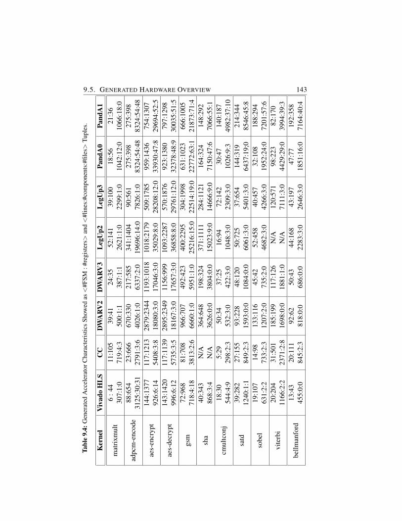
9.5. GENERATED HARDWARE OVERVIEW 143Ta
ble
9.4:
Gen
erat
edA
ccel
erat
orC
hara
cter
istic
sSh
owed
as<
#FSM
:#re
gist
ers>
and<
#lin
es:#
com
pone
nts:
#file
s>Tu
ples
.
Ker
nel
Viv
ado
HL
SC
CD
WA
RV
2D
WA
RV
3L
egU
p2L
egU
p3Pa
ndA
0Pa
ndA
1
mat
rixm
ult
6:4
411
:105
39:4
124
:35
52:1
4139
:100
18:5
621
:36
307:
1:0
719:
4:3
500:
1:1
387:
1:1
2621
:1:0
2299
:1:0
1042
:12:
010
66:1
8:0
adpc
m-e
ncod
e88
:654
23:6
6667
0:33
021
7:58
534
1:14
0490
:561
275:
398
275:
398
3125
:30:
3127
91:3
:640
26:1
:063
37:2
:019
696:
14:0
7826
:1:0
8324
:54:
4883
24:5
4:48
aes-
encr
ypt
144:
1377
117:
1213
2879
:234
411
93:1
018
1018
:217
950
9:17
8595
9:14
3675
4:13
0792
6:6:
1454
08:3
:818
080:
3:0
1704
6:3:
035
029:
8:0
2820
8:12
:033
930:
47:8
2969
4:52
:5
aes-
decr
ypt
143:
1420
117:
1139
2895
:234
911
56:9
9910
93:2
287
570:
1876
923:
1380
797:
1298
996:
6:12
5735
:3:5
1816
7:3:
017
657:
3:0
3685
8:8:
029
761:
12:0
3237
8:48
:930
035:
51:5
gsm
72:9
6881
:708
966:
707
492:
423
400:
2295
304:
1998
631:
1023
666:
1005
718:
4:18
3813
:2:6
6660
:1:0
5951
:1:0
2521
6:15
:022
514:
19:0
2277
2:63
:121
873:
71:4
sha
40:3
43N
/A36
4:64
819
8:32
437
1:11
1128
4:11
2116
4:32
414
8:29
286
8:3:
4N
/A36
26:0
:038
04:0
:015
023:
9:0
1466
6:9:
071
50:4
7:6
7066
:55:
1
cmul
tcon
j18
:30
5:29
50:3
437
:25
16:9
472
:142
30:4
714
0:18
754
4:4:
929
8:2:
353
2:3:
042
2:3:
010
48:3
:023
09:3
:010
26:9
:349
82:3
7:10
satd
39:2
8227
:155
93:2
2848
:120
50:7
2537
:654
144:
319
214:
344
1240
:1:1
849:
2:3
1593
:0:0
1084
:0:0
6061
:3:0
5401
:3:0
6437
:19;
085
46:4
5:8
sobe
l19
:107
14:9
813
3:11
645
:42
52:4
5840
:457
32:1
0818
8:29
463
1:2:
273
3:2:
312
07:2
:073
5:2:
046
82:3
:042
66:3
:019
52:2
4:0
7201
:57:
6
vite
rbi
20:2
0431
:501
185:
199
117:
126
N/A
120:
571
98:2
2382
:170
1166
:2:2
2371
:2:8
1698
:0:0
1881
:1:0
N/A
7111
:3:0
4429
:29:
039
94:3
9:3
bellm
anfo
rd13
:43
20:1
1192
:62
50:4
344
:168
43:1
9747
:77
192:
358
455:
0:0
845:
2:3
818:
0:0
686:
0:0
2283
:3:0
2646
:3:0
1851
:16:
071
64:4
0:4
144 CHAPTER 9. HARDWARE COMPILERS EVALUATIONFig
Page 1
mattrix adpcm_ encode
aes_encrypt aes_decrypt gsm sha cmultconj satd sobel belmannford1.00
1.50
2.00
2.50
3.00
3.50
4.00
Figure 9.2: Execution Time Speedups of DWARV 3.0 compared to DWARV 2.0 .
Frequency (FMax). For example, we can see that, on average, the CC compiler(see below) gives the smallest numbers of FSM states, however, when we com-pute the execution time (i.e., #cycles / FMax) Vivado HLS generated hardwaredesigns execute in less time (see Section 9.7). This implies that generating asfew states as possible is not a criterion of success.
9.6 Experimental Results
We will now present the obtained performance results for the selected compil-ers. Besides DWARV2.0 and DWARV3.0, we investigate the compilers selectedin section 9.3, that is Vivado HLS, LegUp and PandA. For the last two com-pilers, the latest two releases are investigated to track their evolution as wellin a similar manner to the one performed for DWARV. The complete results,including area numbers for all compilers, are presented in Appendix A while,in this section, we show only the performance related metrics. Besides thesecompilers, we include a fifth tool, called here CommercialCompiler (CC) tohide the actual name of the compiler. We do this in order to avoid any licenserelated issues regarding publishing these results. We note that for Figures 9.3and 9.4, the smaller the compiler bar, the better its performance.
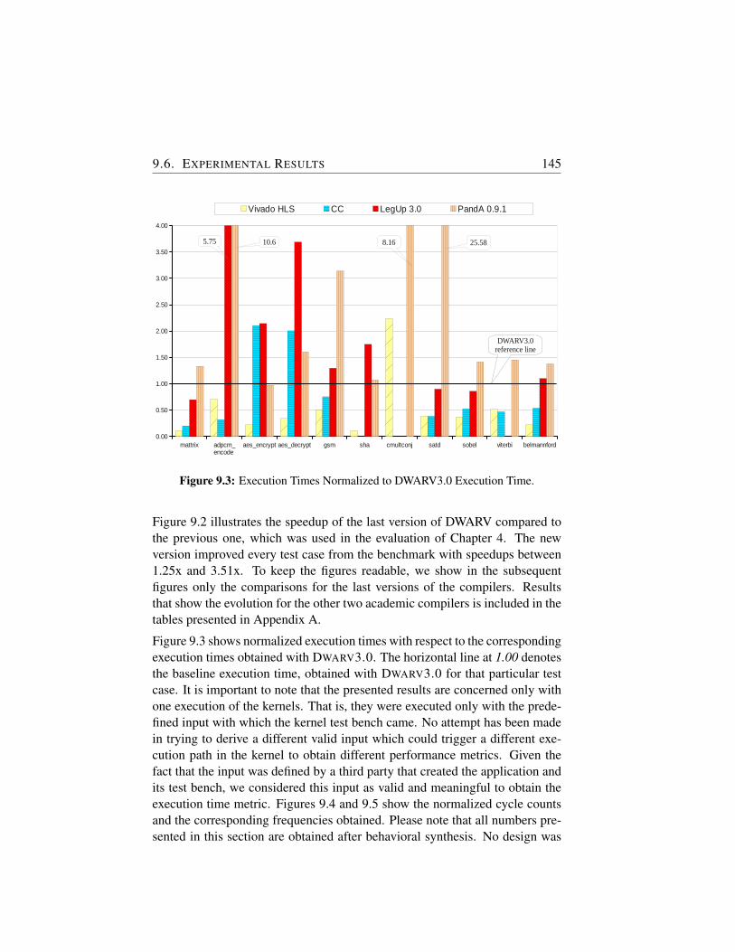
9.6. EXPERIMENTAL RESULTS 145Sheet1
Page 1
mattrix adpcm_ encode
aes_encrypt aes_decrypt gsm sha cmultconj satd sobel viterbi belmannford0.00
0.50
1.00
1.50
2.00
2.50
3.00
3.50
4.00
Vivado HLS CC LegUp 3.0 PandA 0.9.1
10.65.75
DWARV3.0reference line
25.588.16
Figure 9.3: Execution Times Normalized to DWARV3.0 Execution Time.
Figure 9.2 illustrates the speedup of the last version of DWARV compared tothe previous one, which was used in the evaluation of Chapter 4. The newversion improved every test case from the benchmark with speedups between1.25x and 3.51x. To keep the figures readable, we show in the subsequentfigures only the comparisons for the last versions of the compilers. Resultsthat show the evolution for the other two academic compilers is included in thetables presented in Appendix A.
Figure 9.3 shows normalized execution times with respect to the correspondingexecution times obtained with DWARV3.0. The horizontal line at 1.00 denotesthe baseline execution time, obtained with DWARV3.0 for that particular testcase. It is important to note that the presented results are concerned only withone execution of the kernels. That is, they were executed only with the prede-fined input with which the kernel test bench came. No attempt has been madein trying to derive a different valid input which could trigger a different exe-cution path in the kernel to obtain different performance metrics. Given thefact that the input was defined by a third party that created the application andits test bench, we considered this input as valid and meaningful to obtain theexecution time metric. Figures 9.4 and 9.5 show the normalized cycle countsand the corresponding frequencies obtained. Please note that all numbers pre-sented in this section are obtained after behavioral synthesis. No design was
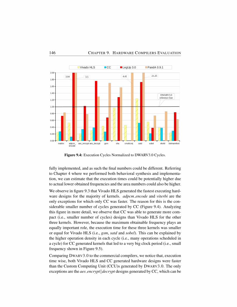
146 CHAPTER 9. HARDWARE COMPILERS EVALUATIONFig
Page 1
mattrix adpcm_ encode
aes_encrypt aes_decrypt gsm sha cmultconj satd sobel viterbi belmannford0.00
0.20
0.40
0.60
0.80
1.00
1.20
1.40
1.60
1.80
2.00
Vivado HLS CC LegUp 3.0 PandA 0.9.1
3.53.04
DWARV3.0reference line
21.254.41
Figure 9.4: Execution Cycles Normalized to DWARV3.0 Cycles.
fully implemented, and as such the final numbers could be different. Referringto Chapter 4 where we performed both behavioral synthesis and implementa-tion, we can estimate that the execution times could be potentially higher dueto actual lower obtained frequencies and the area numbers could also be higher.
We observe in figure 9.3 that Vivado HLS generated the fastest executing hard-ware designs for the majority of kernels. adpcm encode and viterbi are theonly exceptions for which only CC was faster. The reason for this is the con-siderable smaller number of cycles generated by CC (Figure 9.4). Analyzingthis figure in more detail, we observe that CC was able to generate more com-pact (i.e., smaller number of cycles) designs than Vivado HLS for the otherthree kernels. However, because the maximum obtainable frequency plays anequally important role, the execution time for these three kernels was smalleror equal for Vivado HLS (i.e., gsm, satd and sobel). This can be explained bythe higher operation density in each cycle (i.e., many operations scheduled ina cycle) for CC generated kernels that led to a very big clock period (i.e., smallfrequency shown in Figure 9.5).
Comparing DWARV3.0 to the commercial compilers, we notice that, executiontime wise, both Vivado HLS and CC generated hardware designs were fasterthan the Custom Computing Unit (CCU)s generated by DWARV3.0. The onlyexceptions are the aes encrypt||decrypt designs generated by CC, which can be
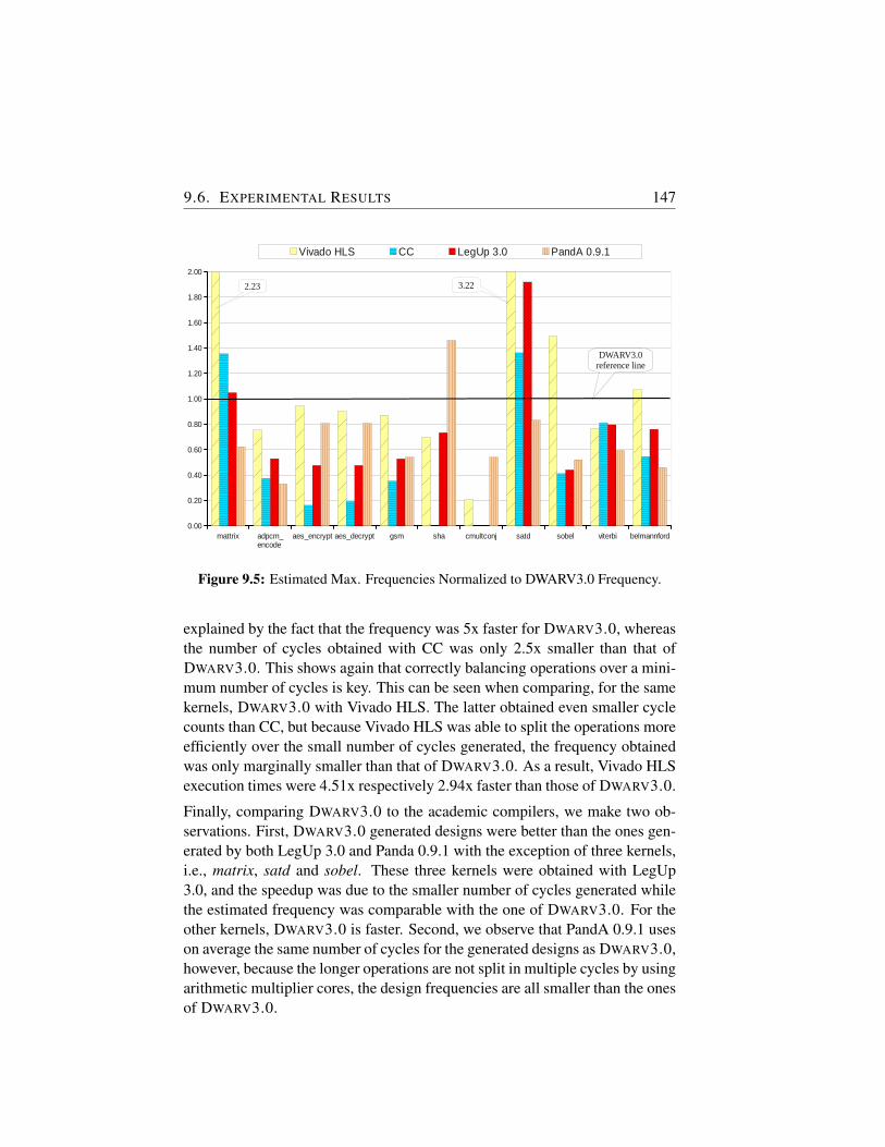
9.6. EXPERIMENTAL RESULTS 147Fig
Page 1
mattrix adpcm_ encode
aes_encrypt aes_decrypt gsm sha cmultconj satd sobel viterbi belmannford0.00
0.20
0.40
0.60
0.80
1.00
1.20
1.40
1.60
1.80
2.00
Vivado HLS CC LegUp 3.0 PandA 0.9.1
2.23
DWARV3.0reference line
3.22
Figure 9.5: Estimated Max. Frequencies Normalized to DWARV3.0 Frequency.
explained by the fact that the frequency was 5x faster for DWARV3.0, whereasthe number of cycles obtained with CC was only 2.5x smaller than that ofDWARV3.0. This shows again that correctly balancing operations over a mini-mum number of cycles is key. This can be seen when comparing, for the samekernels, DWARV3.0 with Vivado HLS. The latter obtained even smaller cyclecounts than CC, but because Vivado HLS was able to split the operations moreefficiently over the small number of cycles generated, the frequency obtainedwas only marginally smaller than that of DWARV3.0. As a result, Vivado HLSexecution times were 4.51x respectively 2.94x faster than those of DWARV3.0.
Finally, comparing DWARV3.0 to the academic compilers, we make two ob-servations. First, DWARV3.0 generated designs were better than the ones gen-erated by both LegUp 3.0 and Panda 0.9.1 with the exception of three kernels,i.e., matrix, satd and sobel. These three kernels were obtained with LegUp3.0, and the speedup was due to the smaller number of cycles generated whilethe estimated frequency was comparable with the one of DWARV3.0. For theother kernels, DWARV3.0 is faster. Second, we observe that PandA 0.9.1 useson average the same number of cycles for the generated designs as DWARV3.0,however, because the longer operations are not split in multiple cycles by usingarithmetic multiplier cores, the design frequencies are all smaller than the onesof DWARV3.0.

148 CHAPTER 9. HARDWARE COMPILERS EVALUATION
Table 9.5: Execution Time Slowdowns compared to Vivado HLS.
F. Name V.HLS CC D2.0 D3.0 L2.0 L3.0 P0.9.1matrixmult 1 1.79 20.77 8.84 11.81 6.16 11.77
adpcm-encode 1 0.46 3.93 1.43 5.83 8.20 15.11aes-encrypt 1 9.49 8.87 4.51 15.84 9.67 4.39aes-decrypt 1 5.90 10.37 2.94 21.03 10.85 4.72
gsm 1 1.51 5.13 2.01 38.04 2.60 6.30sha 1 N/A N/A 9.28 20.09 16.22 9.96
cmultconj 1 N/A 0.64 0.45 1.78 N/A 3.65satd 1 1.00 3.34 2.60 2.28 2.34 66.49sobel 1 1.42 5.45 2.69 2.50 2.31 3.80viterbi 1 0.92 N/A 1.95 N/A N/A 2.84
bellmanford 1 2.41 10.02 4.49 6.82 4.94 6.18AVERAGE 1 3.11 7.92 3.74 12.60 7.03 12.29GEOMEAN 1 1.96 5.53 2.81 8.10 5.66 7.24
9.7 Conclusion
In this chapter, we compared a number of hardware compilers that complywith all the criteria defined in Section 9.2 for a hardware compiler evalua-tion in which DWARV can be included, as well. In particular, we looked atVivado HLS, ComercialCompiler, LegUp2.0 and 3.0, PandA 0.9.0 and 0.9.1,and two versions of DWARV, i.e., 2.0 and 3.0. Table 9.5 shows the final ex-ecution time slowdowns when comparing to Vivado HLS, which on averagegenerated the most efficient hardware. The final row shows the geometricmeans for the performance of all tools compared to Vivado HLS. We can seehere that DWARV3.0 is 2.81x slower than Vivado HLS, but also that a visibleprogress has been obtained since DWARV2.0 only by adding the optimizationsdescribed in Chapter 8. That is, DWARV3.0 is 1.96x faster than DWARV2.0.Finally, the performed experiments revealed that DWARV3.0 performed thebest between all versions of all academically available compilers.
Note.
The content of this chapter was submitted as part of the following publication:
R. Nane, V.M. Sima, K.L.M. Bertels, A Survey of High-Level Synthesis Toolsand Comparison with DWARV 3.0, Submitted to IEEE Transactions onComputer-Aided Design of Integrated Circuits and Systems, April 2014.
10Conclusions and Future Work
IN this dissertation, we addressed different problems related to the processof automatic hardware generation for reconfigurable architectures. Con-cretely, we analyzed, designed, and implemented a hardware compiler
in a commercial retargetable compiler framework. Subsequently, we studiedtwo optimization problems concerning how area input constraints should bepropagated in a High-Level Synthesis (HLS) tool as well as how the softwareif-conversion optimization can be applied in a hardware generation context.At the same time, we started to investigate the general problem of how ex-isting software optimizations can be included in a hardware compiler. Fur-thermore, we investigated how and what is required to be generated, so thatautomatically generated hardware blocks can be integrated in complex (i.e.,hardware/software co-designed) systems automatically. Finally, we performeda thorough evaluation of past and present HLS tools, while, at the same time,we benchmarked DWARV3.0 against both state-of-the-art commercial and aca-demic compilers.
10.1 Summary
The different problems addressed in this work are split in chapters as follows:
In Chapter 2, we presented related work in which a vast number of past andpresent hardware compiler were described. These were categorized based onthe design language in domain-specific respectively generic HLS tools. Theparticular tool description included information such as for what applicationdomain the tool can be used, what extensions are required, if the tool offersverification support, as well as under what type of license it is available (com-mercial or academic). Finally, we commented for each tool how it is differentfrom DWARV.
149
150 CHAPTER 10. CONCLUSIONS AND FUTURE WORK
In Chapter 3, the underlying concepts and the compiler framework usedthroughout the work were presented. We described the Molen Machine Orga-nization, the first version of the DWARV compiler which provided the inspira-tion for the current version, and we provided detailed information regarding theCoSy compiler framework used to implement the new version of DWARV. Wealso described the simulation and synthesis flows used to validate and imple-ment automatically generated hardware designs. Finally, we discussed impor-tant similarities and differences between software and hardware compilers andwe described the complete C-to-FPGA tool-flow based on a simple example.
Chapter 4 presented the first DWARV implementation in CoSy. The per-formance of this version was benchmarked by comparing and evaluating itagainst the LegUp 2.0 academic compiler. The results obtained showed thatDWARV2.0 was outperforming LegUp 2.0.
In Chapter 5, we described the need for Hardware-dependent Software (HdS)when integrating automatically generated hardware blocks in complex Systemon Chip (SoC) systems. Furthermore, the use of HdS for hardware blocks ledto the proposition of HdS related extensions to the IP-XACT standard, stan-dard that facilitates the automatic integration of existing hardware componentsused by hardware designers for SoC design.
In Chapter 6, an optimization algorithm to generate hardware kernels subjectto input area constraints was presented. These area constraints are highly im-portant in the Molen context, where a maximum number of accelerators canbe executed in parallel by a particular machine implementation. In this re-spect, generating hardware accelerators that can fit these previously definedFPGA slots is very important. However, the approach is generic enough to beapplicable on different hardware platforms.
Next chapter, Chapter 7, presented another hardware specific optimization.This optimization, called Speculative and Predicative Algorithm (SaPA), isbased on a relaxation of the traditional software if-conversion technique. Theresults obtained indicate that this optimization could be universally applied ineach hardware compiler because it does not decrease the accelerator perfor-mance in unbalanced if-then-else cases, while, at the same time, the hardwarearea is negligibly increased.
In Chapter 8, we presented important hardware optimizations that allowed tooptimize DWARV2.0 by a factor of 2x to 3x. Furthermore, we initiated worktowards the automation of selecting and integrating optimizations in a compileron a case by case basis. The reason behind this work is the fact that includingexisting standard optimizations randomly in a compiler is not a recipe for suc-
10.2. DISSERTATION CONTRIBUTIONS 151
cess. The order in which these are applied and how they are configured play avery important role, as well.
Finally, Chapter 9, showed comparison results for DWARV3.0 against a newerversion of LegUp (i.e., LegUp 3.0) and other three compilers, i.e., Vivado HLS,PandA 0.9.1 and another CommercialCompiler.
10.2 Dissertation Contributions
In recent years, we have seen an increase in the use of reconfigurable devicessuch as FPGAs, as well as an increase in the availability of commercial het-erogeneous platforms containing both software processors and reconfigurablehardware. Examples include Convey HPC, Xilinx Zync and IBM Power7 withFPGA blades. However, as we argued in the introduction, programming thesedevices is still very challenging. As a result, the main goal of this disserta-tion was to advance the field of HLS. Concretely, we proposed methods toboth integrate and optimize hardware compilers used for generating efficienthardware code that can be executed on such heterogeneous computers.
The specific contributions of this thesis are summarized as follows:
• We designed, implemented, and evaluated a new research compilerbased on the CoSy commercial compiler framework. This new ver-sion of DWARV has a higher coverage of accepted C-language con-structs. This is because the underlying compiler framework offers stan-dard lowering (i.e., from high- to low-level constructs mapping) trans-formations, which essentially allows the developer to implement just theimportant primitives (e.g., goto) from which all high-level constructs arecomposed. Furthermore, using CoSy, we obtained a highly robust andmodular compiler that can be integrated in different tool-chains by ex-tending it with custom compiler transformations to process third partyinformation (e.g., coming from aspect oriented descriptions) and config-ure the process of hardware generation accordingly. We validated anddemonstrated the performance of the DWARV2.0 compiler against an-other state-of-the-art research compiler. We showed in this initial com-parison kernel wise performance improvements up to 4.41x comparedto LegUp 2.0 compiler (Chapter 4).
• We proposed IP-XACT extensions and showed that HdS should accom-pany hardware kernels to make them generally integrable into third party
152 CHAPTER 10. CONCLUSIONS AND FUTURE WORK
tool(-chains). Therefore, we elaborated on the expressiveness of IP-XACT for describing HdS meta-data. Furthermore, we addressed theautomation of HdS generation in the Reconfigurable Computing (RC)field, where Intellectual Property (IP)s and their associated HdS are gen-erated on the fly, and, therefore, are not predefined. We combined in thisrespect two proven technologies used in MPSoC design, namely IP-XACT and HdS, to integrate automatically different architectural tem-plates used in RC systems. We investigated and proposed IP-XACTextensions to allow this automatic generation and integration of HdS inRC tool-chains (Chapter 5).
• We proposed an optimization to control the unroll factor and the numberof components when the area available for the kernel is limited. We as-sumed thus that the hardware area for which a to be generated hardwareaccelerator is limited. In this respect, two important parameters had to beexplored namely, the degree of parallelism (i.e., the loop unrolling fac-tor) and the number of functional modules (e.g., Floating-Point (FP) addoperation) used to implement the source High-Level Language (HLL)code. Determining without any human intervention these parameters is akey factor in building efficient HLL-to-Hardware Description Language(HDL) compilers, and implicitly any Design Space Exploration (DSE)tools. To solve this problem, we proposed an optimization algorithmto compute the above parameters automatically. This optimization wasadded as an extension to the DWARV2.0 hardware compiler (Chapter 6).
• We proposed a predication scheme suitable and generally applicable forhardware compilers called SaPA. This technique takes into account thecharacteristics of a C-to-VHDL compiler and the features available onthe target platform. Instruction predication is an already known compileroptimization technique, however, according to our knowledge and liter-ature searches, current C-to-VHDL compilers do not take fully advan-tage of the possibilities offered by this optimization. More specifically,we proposed a method to increase the performance in the case of un-balanced if-then-else branches. These types of branches are problematicbecause, when the jump instructions are removed for the predicated exe-cution if the shorter branch is taken, slowdowns occur because (useless)instructions from the longer branch still need to be executed. Based onboth synthetic and real world applications we showed that our algorithmdoes not substantially increase the resource usage while the executiontime is reduced in all cases for which it is applied (Chapter 7).
10.3. FUTURE WORK 153
• We provided an evaluation of state-of-the-art hardware compilersagainst DWARV3.0. At the same time, a thorough retrospection of ex-isting HLS tools has been performed. The comparison included a num-ber of hardware compilers that comply with some predefined criteria inwhich DWARV can be included, as well. In particular, we looked at Vi-vadoHLS, another ComercialCompiler, LegUp2.0 and 3.0, PandA 0.9.0and 0.9.1, and two versions of DWARV, i.e., 2.0 and 3.0. The results ob-tained showed how all these compilers compare to Vivado HLS, whichon average generated the most efficient hardware (Chapters 2, 8 and 9).
10.3 Future Work
We identify five major follow up research directions that we summarize below:
• The first and most important one is the continuation of the investiga-tion related to how existing software optimizations can be applied to thehardware generation process. In this respect, questions such as what isthe best place to insert an optimization in the compiler’s flow of trans-formations, or how should a software optimization be customized and/orconfigured to generate optimal hardware, are very important. The im-portance of these questions, explained in Chapter 8, can be summarizedbriefly by stating that only including existing standard optimizations ran-domly in a compiler is not a recipe for success. The order in which theseare applied and how they are configured are also important. Further-more, given that there is still a considerable performance gap betweenthe manually written hardware designs and those automatically gener-ated, the search and invention of new specific hardware optimizationscan play a major role also in the success and wide adoption of HLStools. In this respect, the search of such new optimizations can be in-spired by existing software optimizations, as it was the case with SaPApresented in Chapter 7.
• The second major research direction concerns the further investigationof the IP-XACT standard to support automatic generation of completereconfigurable systems that embed automatically generated hardwareblocks. That is, given that, for an individual core, we know how andwhat to generate to facilitate its integration in a SoC system (see Chapter5), the question of what IP-XACT extensions are needed to allow theinference of system knowledge about interface and interconnect types
154 CHAPTER 10. CONCLUSIONS AND FUTURE WORK
necessary to generate complete SoC systems automatically should beresearched subsequently.
• Third, the model presented in Chapter 6 should be extended to allowdealing with variable loop bounds. In addition, more accurate predictionmodels for the wiring increase as well as for the power consumption areneeded.
• Fourth, we intend to extend the comparison performed in Chapter 9 tocreate a state-of-the-art benchmarking reference result point to which allfuture compilers can relate. We will do this not only restricting it for thegeneral domain, but also extending it to a broader scope of includingparticular domains and their corresponding audience tools. For exam-ple, one such domain would be the streaming one, where tools such asROCCC could be included.
• Finally, a very interesting topic, which was not addressed in this disser-tation, is to study the impact on performance of data partitioning and/ormemory architecture generated by HLS tools. Topics, such as how manymemory banks are sufficient for a particular hardware accelerator to sat-isfy the required performance throughput, or what type of acceleratorinterconnection can be used to communicate/transfer data efficiently inthe system are examples of such system level design questions.
AComplete DWARV 3.0 Comparison
Results
IN this Appendix, we present with the help of Tables A.1 to A.4 the com-plete set of results obtained in Chapter 9 for all compilers. Furthermore,we explain for each tool the difficulties faced in compiling particular ex-
amples or we comment on the correctness of the result.
Vivado HLS and CommercialCompiler (CC)
We start the presentation with the commercial compilers. The results ob-tained from (behaviorally) synthesizing the kernels obtained by compiling theC benchmark functions, with the clock period set to 10 ns, are shown in TableA.1. We note for these tools two benchmarks that we need to explain. First,the cmultconj caused problems for both commercial compilers. Because CCdoes not have floating-point capabilities, it could not compile this kernel atall. VIVADO HLS was able to compile it; however, the result obtained is theonly one that is performing worse than the corresponding result obtained withDWARV3.0. A closer examination revealed that this is caused by the place-ment of the floating-point core in relation to the input register. This criticalpath with total delay of 16.096 ns is composed of 5.465 ns logic and 10.631ns routing. Why Xilinx ISE’s xst compiler was unable to place the input reg-ister closer to the floating-point core, is not clear. A possible cause could bean incompatibility between Vivado and ISE synthesis algorithms. That is, wesuspect the problem could be caused by the fact that the hardware design ob-tained with Vivado HLS was synthesized using ISE’s xst tool, which relies onolder synthesizing algorithms. Finally, the sha function could not be compiledwith CC because the tool gave a segmentation fault in this case.
155
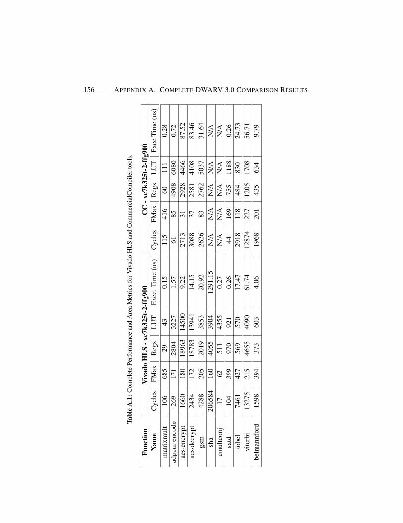
156 APPENDIX A. COMPLETE DWARV 3.0 COMPARISON RESULTS
Tabl
eA
.1:C
ompl
ete
Perf
orm
ance
and
Are
aM
etri
csfo
rViv
ado
HL
San
dC
omm
erci
alC
ompi
lert
ools
.
Func
tion
Viv
ado
HL
S-x
c7k3
25t-
2-ff
g900
CC
-xc7
k325
t-2-
ffg9
00N
ame
Cyc
les
FMax
Reg
sL
UT
Exe
c.Ti
me
(us)
Cyc
les
FMax
Reg
sL
UT
Exe
cTi
me
(us)
mat
rixm
ult
106
685
2943
0.15
115
416
6011
10.
28ad
pcm
-enc
ode
269
171
2804
3227
1.57
6185
4908
6080
0.72
aes-
encr
ypt
1660
180
1896
314
500
9.22
2713
3129
2844
6687
.52
aes-
decr
ypt
2434
172
1878
313
941
14.1
530
8837
2581
4108
83.4
6gs
m42
8820
520
1938
5320
.92
2626
8327
6250
3731
.64
sha
2065
8416
040
5539
0412
91.1
5N
/AN
/AN
/AN
/AN
/Acm
ultc
onj
1762
511
4355
0.27
N/A
N/A
N/A
N/A
N/A
satd
104
399
970
921
0.26
4416
975
511
880.
26so
bel
7461
427
569
570
17.4
729
1811
848
483
024
.73
vite
rbi
1327
521
546
5540
9061
.74
1287
422
712
0517
0856
.71
belm
annf
ord
1598
394
373
603
4.06
1968
201
435
634
9.79
157
DWARV 2.0 and DWARV 3.0
Table A.2 shows the complete results for the last two versions of DWARV,without and with the modifications of Chapter 8. We notice two cases here,i.e. sha and viterbi functions that DWARV2.0 was able to compile, however,the simulation results did not match the golden reference obtained by runningthe function in software. As a result, we considered these hardware designsincorrect, and we didn’t attempt to synthesize them.
LegUp 2.0 and LegUp 3.0
Table A.3 gives the results for 2.0 and 3.0 versions of LegUp. We see in thetable that, for the older version, the viterbi function did not compile. This isdenoted by the ERR entry in the table. We note that all the kernels compiledwith LegUp 2.0 were synthesized with Quartus toolset 10.0 for the Stratix IVEP4SGX70HF35C2 FPGA. For LegUp 3.0, we used two FPGAs, one fromAltera and one from Xilinx. The reason is because we wanted to keep theconsistency in the comparison by comparing outputs of the same synthesizingcompiler for the same target FPGA. However, because LegUp is designed forAltera, we could not synthesize all kernels for Xilinx. The ones requiringspecial cores, i.e. a lpm divide Altera specific divider, were synthesized withQuartus 11.1sp for the Cyclone 2 EP2C35F672C6 FPGA. We did not choosefor the Stratix version because LegUp 3.0 gives errors when we try to selectit. Furthermore, with LegUp 3.0, two functions caused problems. cmultconjfunction could not be compiled due to missing floating-point cores and viterbikernel did not give correct results in simulation.
PandA 0.9.0 and PandA 0.9.1
Finally, Table A.4 presents the results for PandA 0.9.0 and PandA 0.9.1 toolversions. We notice that the former version could not generate test benchesfor all the cases, although the tool was able to compile that particular func-tion. This is the case for the adpcm-encode, aes-encrypt‖decrypt and shafunctions. As a result, we were not able to calculate performance numbersfor them. However, the latest tool version is able to generate both kernels andtheir corresponding test benches correctly for all benchmark functions.
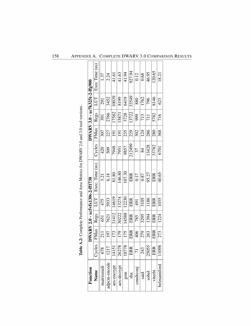
158 APPENDIX A. COMPLETE DWARV 3.0 COMPARISON RESULTS
Tabl
eA
.2:C
ompl
ete
Perf
orm
ance
and
Are
aM
etri
csfo
rDW
ARV
2.0
and
3.0
tool
vers
ions
.
Func
tion
DW
AR
V2.
0-x
c5vf
x130
t-2-
ff17
38D
WA
RV
3.0
-xc7
k325
t-2-
ffg9
00N
ame
Cyc
les
FMax
Reg
sL
UT
Exe
c.Ti
me
(us)
Cyc
les
FMax
Reg
sL
UT
Exe
cTi
me
(us)
mat
rixm
ult
678
211
651
475
3.21
420
307
391
291
1.37
adpc
m-e
ncod
e12
1719
776
2159
336.
1850
922
727
6634
522.
24ae
s-en
cryp
t14
151
173
3141
214
619
81.8
079
4819
117
582
1003
941
.61
aes-
decr
ypt
2627
817
930
222
1327
414
6.80
7951
191
1587
181
9941
.63
gsm
1877
817
514
588
1223
010
7.30
9857
235
3728
6419
41.9
4sh
aE
RR
ER
RE
RR
ER
RE
RR
2124
9922
913
722
3354
992
7.94
cmul
tcon
j71
406
785
491
0.17
3730
299
988
00.
12sa
td24
327
932
9531
050.
8784
124
713
1762
0.68
sobe
l25
055
263
1394
1186
95.2
713
428
286
711
796
46.9
5vi
terb
iE
RR
ER
RE
RR
ER
RE
RR
3378
228
057
8281
4612
0.65
belm
annf
ord
1109
827
312
2410
3540
.65
6701
368
716
623
18.2
1
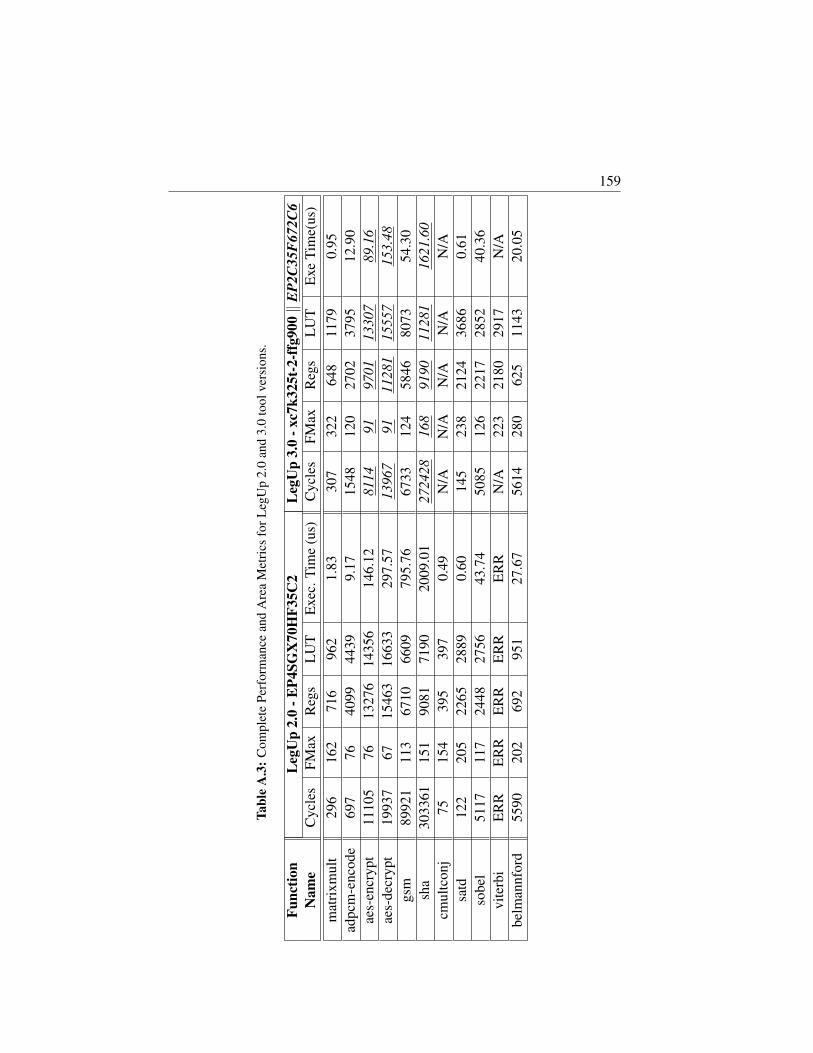
159
Tabl
eA
.3:C
ompl
ete
Perf
orm
ance
and
Are
aM
etri
csfo
rLeg
Up
2.0
and
3.0
tool
vers
ions
.
Func
tion
Leg
Up
2.0
-EP4
SGX
70H
F35C
2L
egU
p3.
0-x
c7k3
25t-
2-ff
g900‖
EP2
C35
F67
2C6
Nam
eC
ycle
sFM
axR
egs
LU
TE
xec.
Tim
e(u
s)C
ycle
sFM
axR
egs
LU
TE
xeTi
me(
us)
mat
rixm
ult
296
162
716
962
1.83
307
322
648
1179
0.95
adpc
m-e
ncod
e69
776
4099
4439
9.17
1548
120
2702
3795
12.9
0ae
s-en
cryp
t11
105
7613
276
1435
614
6.12
8114
9197
0113
307
89.1
6ae
s-de
cryp
t19
937
6715
463
1663
329
7.57
1396
791
1128
115
557
153.
48gs
m89
921
113
6710
6609
795.
7667
3312
458
4680
7354
.30
sha
3033
6115
190
8171
9020
09.0
127
2428
168
9190
1128
116
21.6
0cm
ultc
onj
7515
439
539
70.
49N
/AN
/AN
/AN
/AN
/Asa
td12
220
522
6528
890.
6014
523
821
2436
860.
61so
bel
5117
117
2448
2756
43.7
450
8512
622
1728
5240
.36
vite
rbi
ER
RE
RR
ER
RE
RR
ER
RN
/A22
321
8029
17N
/Abe
lman
nfor
d55
9020
269
295
127
.67
5614
280
625
1143
20.0
5
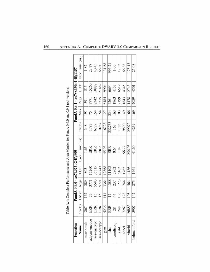
160 APPENDIX A. COMPLETE DWARV 3.0 COMPARISON RESULTS
Tabl
eA
.4:C
ompl
ete
Perf
orm
ance
and
Are
aM
etri
csfo
rPan
dA0.
9.0
and
0.9.
1to
olve
rsio
ns.
Func
tion
Pand
A0.
9.0
-xc7
k325
t-2-
ffg9
00Pa
ndA
0.9.
1-x
c7vx
330t
-1-f
fg11
57N
ame
Cyc
les
FMax
Reg
sL
UT
Exe
c.Ti
me
(us)
Cyc
les
FMax
Reg
sL
UT
Exe
cTi
me
(us)
mat
rixm
ult
267
162
389
803
1.65
348
191
391
515
1.82
adpc
m-e
ncod
eE
RR
7537
7115
260
ER
R17
8375
3771
1526
023
.77
aes-
encr
ypt
ER
R15
5583
3531
5E
RR
6229
154
8342
1888
740
.45
aes-
decr
ypt
ER
R15
5721
4274
3E
RR
1028
715
485
1521
482
66.8
0gs
m52
3611
433
6412
868
45.9
316
723
127
6484
9904
131.
68sh
aE
RR
1713
8811
108
ER
R33
2733
334
4261
6694
996.
21cm
ultc
onj
2844
237
2962
0.64
163
163
1963
4157
1.00
satd
248
136
1223
5163
1.82
1785
103
2199
6519
17.3
3so
bel
7267
128
744
1765
56.7
798
9014
918
4343
4566
.38
vite
rbi
2688
310
556
441
8625
6.03
2907
216
614
7827
4317
5.13
belm
annf
ord
5907
142
273
1461
41.6
042
3916
920
8945
0125
.08
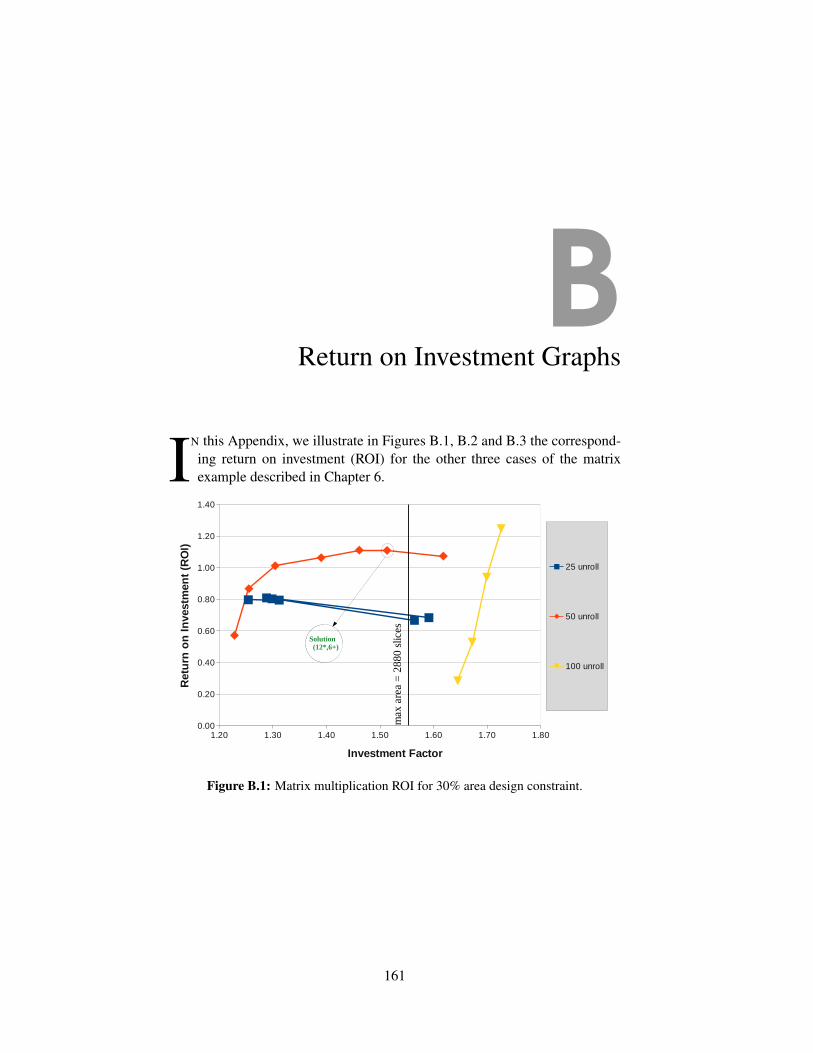
BReturn on Investment Graphs
IN this Appendix, we illustrate in Figures B.1, B.2 and B.3 the correspond-ing return on investment (ROI) for the other three cases of the matrixexample described in Chapter 6.
m_30
Page 1
name area transfer time: 7285PrevSolution20% 25u,10+,5* 1854 990 0 0 0
25 unroll X investment X gain ROI13MUL_6ADD 2325 990 8275 13*,6+ 50*, 25+ 1.25 1.00 0.80
13MUL_7ADD_SOL 2432 950 8235 13*,7+ 50*, 25+ 1.31 1.04 0.7914MUL_7ADD 2407 950 8235 14*,7+ 50*, 25+ 1.30 1.04 0.8015MUL_7ADD 2900 950 8235 15*,7+ 50*, 25+ 1.56 1.04 0.6716MUL_8ADD 2388 950 8235 16*,8+ 50*, 25+ 1.29 1.04 0.8117MUL_9ADD 2950 910 8195 17*,9+ 50*, 25+ 1.59 1.09 0.68
50 unroll 2MUL_1ADD 2277 1410 8695 2*,1+ 100*, 50+ 1.23 0.70 0.574MUL_2ADD 2327 910 8195 4*,2+ 100*, 50+ 1.26 1.09 0.876MUL_3ADD 2418 750 8035 6*,3+ 100*, 50+ 1.30 1.32 1.018MUL_4ADD 2577 670 7955 8*,4+ 100*, 50+ 1.39 1.48 1.06
10MUL_5ADD 2709 610 7895 10*, 5+ 100*, 50+ 1.46 1.62 1.1112MUL_6ADD 2805 590 7875 12*,6+ 100*, 50+ 1.51 1.68 1.11
13MUL_7ADD_SOL 3000 570 7855 13*,7+ 100*, 50+ 1.62 1.74 1.07100 unroll
3050 2120 9405 1*,1+ 200*,100+ 1.65 0.47 0.282MUL_1ADD 3100 1120 8405 2*,1+ 200*,100+ 1.67 0.88 0.534MUL_2ADD 3150 620 7905 4*,2+ 200*,100+ 1.70 1.60 0.946MUL_3ADD 3200 460 7745 6*,3+ 200*,100+ 1.73 2.15 1.25
exec.time
lim
1.20 1.30 1.40 1.50 1.60 1.70 1.800.00
0.20
0.40
0.60
0.80
1.00
1.20
1.40
25 unroll
50 unroll
100 unroll
Investment Factor
Ret
urn
on
In
vest
men
t (R
OI)
max
are
a =
288
0 sl
ices
Solution (12*,6+)
Figure B.1: Matrix multiplication ROI for 30% area design constraint.
161
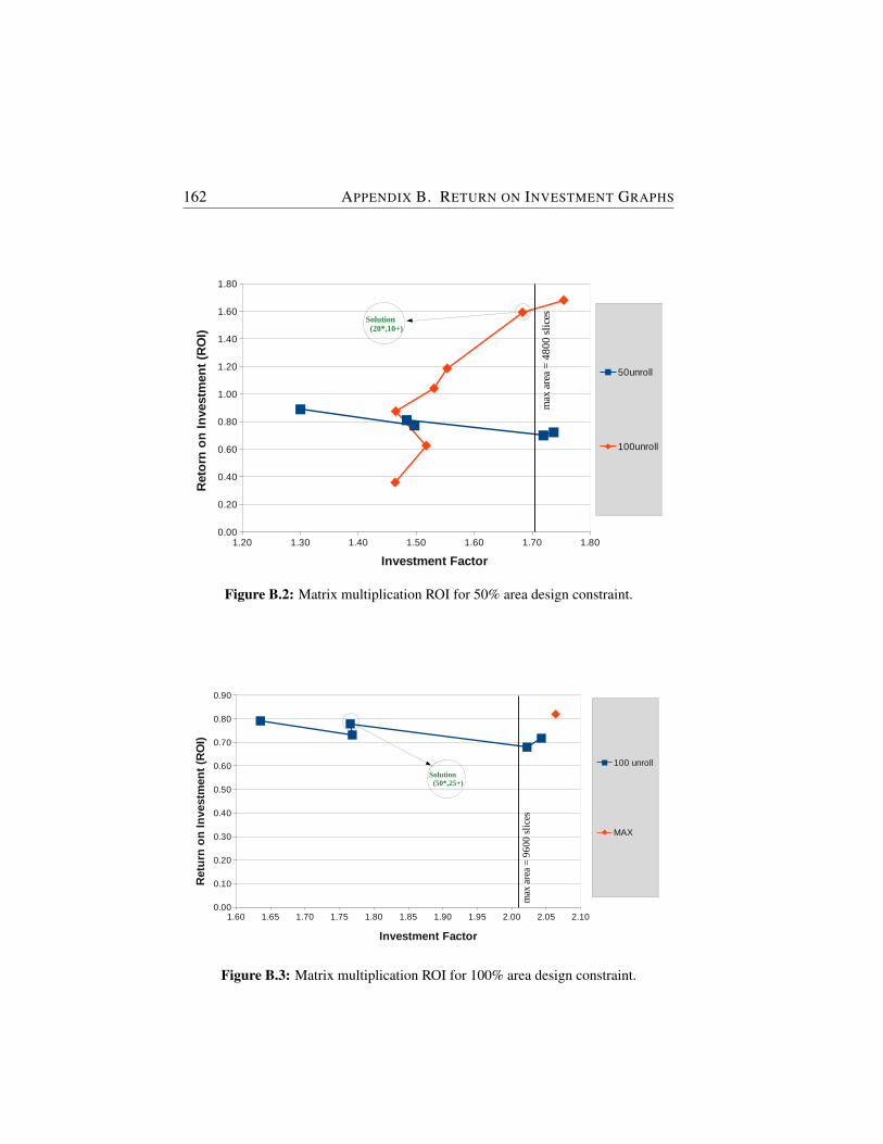
162 APPENDIX B. RETURN ON INVESTMENT GRAPHS
m_50
Page 1
name area exec time exec. Time: 72852850 590
50unroll X investment X gain ROI20MUL_10ADD 3705 510 7795 20*,10+ 100*, 50+ 1.30 1.16 0.8925MUL_12ADD 4266 510 7795 25*,12+ 100*, 50+ 1.50 1.16 0.77
25MUL_13ADD_SOL 4228 490 7775 25*,13+ 100*, 50+ 1.48 1.20 0.8134MUL_16ADD 4900 490 7775 34*,16+ 100*, 50+ 1.72 1.20 0.7034MUL_17ADD 4950 470 7755 34*,17+ 100*, 50+ 1.74 1.26 0.72
100unroll 2MUL_1ADD 4171 1120 8405 2*,1+ 200*,100+ 1.46 0.53 0.364MUL_2ADD 4324 620 7905 4*,2+ 200*,100+ 1.52 0.95 0.636MUL_3ADD 4174 460 7745 6*,3+ 200*,100+ 1.46 1.28 0.888MUL_4ADD 4362 370 7655 8*,4+ 200*,100+ 1.53 1.59 1.0410MUL_5ADD 4427 320 7605 10*, 5+ 200*,100+ 1.55 1.84 1.19
20MUL_10ADD 4797 220 7505 20*,10+ 200*,100+ 1.68 2.68 1.5925MUL_13ADD 5000 200 7485 25*,13+ 200*,100+ 1.75 2.95 1.68
Prevsol 30%25unroll, 13*,6+
1.20 1.30 1.40 1.50 1.60 1.70 1.800.00
0.20
0.40
0.60
0.80
1.00
1.20
1.40
1.60
1.80
50unroll
100unroll
Investment Factor
Ret
orn
on
In
vest
men
t (R
OI)
max
are
a =
480
0 sl
icesSolution
(20*,10+)
Figure B.2: Matrix multiplication ROI for 50% area design constraint.
m_100
Page 1
name area exec time 72854797 220
100 unroll X investment X gain ROI40MUL_20ADD 7845 170 7455 1.64 1.29 0.7950MUL_24ADD 8484 170 7455 1.77 1.29 0.73
50MUL_25ADD_SOL 8470 160 7445 1.77 1.38 0.7867MUL_33ADD 9700 160 7445 2.02 1.38 0.6867MUL_34ADD 9800 150 7435 2.04 1.47 0.72
MAX 9900 130 2.06 1.69 0.82
prevsol: 100unroll, 20*,10+ prevsol: 100unroll, 20*,10+
1.60 1.65 1.70 1.75 1.80 1.85 1.90 1.95 2.00 2.05 2.100.00
0.10
0.20
0.30
0.40
0.50
0.60
0.70
0.80
0.90
100 unroll
MAX
Investment Factor
Ret
urn
on
In
vest
men
t (R
OI)
max
are
a =
960
0 sl
ices
Solution (50*,25+)
Figure B.3: Matrix multiplication ROI for 100% area design constraint.
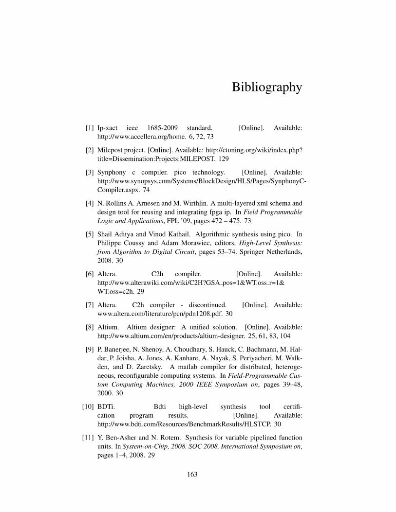
Bibliography
[1] Ip-xact ieee 1685-2009 standard. [Online]. Available:http://www.accellera.org/home. 6, 72, 73
[2] Milepost project. [Online]. Available: http://ctuning.org/wiki/index.php?title=Dissemination:Projects:MILEPOST. 129
[3] Synphony c compiler. pico technology. [Online]. Available:http://www.synopsys.com/Systems/BlockDesign/HLS/Pages/SynphonyC-Compiler.aspx. 74
[4] N. Rollins A. Arnesen and M. Wirthlin. A multi-layered xml schema anddesign tool for reusing and integrating fpga ip. In Field ProgrammableLogic and Applications, FPL ’09, pages 472 – 475. 73
[5] Shail Aditya and Vinod Kathail. Algorithmic synthesis using pico. InPhilippe Coussy and Adam Morawiec, editors, High-Level Synthesis:from Algorithm to Digital Circuit, pages 53–74. Springer Netherlands,2008. 30
[6] Altera. C2h compiler. [Online]. Available:http://www.alterawiki.com/wiki/C2H?GSA pos=1&WT.oss r=1&WT.oss=c2h. 29
[7] Altera. C2h compiler - discontinued. [Online]. Available:www.altera.com/literature/pcn/pdn1208.pdf. 30
[8] Altium. Altium designer: A unified solution. [Online]. Available:http://www.altium.com/en/products/altium-designer. 25, 61, 83, 104
[9] P. Banerjee, N. Shenoy, A. Choudhary, S. Hauck, C. Bachmann, M. Hal-dar, P. Joisha, A. Jones, A. Kanhare, A. Nayak, S. Periyacheri, M. Walk-den, and D. Zaretsky. A matlab compiler for distributed, heteroge-neous, reconfigurable computing systems. In Field-Programmable Cus-tom Computing Machines, 2000 IEEE Symposium on, pages 39–48,2000. 30
[10] BDTi. Bdti high-level synthesis tool certifi-cation program results. [Online]. Available:http://www.bdti.com/Resources/BenchmarkResults/HLSTCP. 30
[11] Y. Ben-Asher and N. Rotem. Synthesis for variable pipelined functionunits. In System-on-Chip, 2008. SOC 2008. International Symposium on,pages 1–4, 2008. 29
163
164 BIBLIOGRAPHY
[12] Koen Bertels, Stamatis Vassiliadis, Elena Moscu Panainte, YanaYankova, Carlo Galuzzi, Ricardo Chaves, and Georgi Kuzmanov. De-veloping applications for polymorphic processors: The delft workbench.Technical report, Delft University of Technology, 2006. 39
[13] BlueSpec. High-level synthesis tools. [Online]. Available:http://bluespec.com/high-level-synthesis-tools.html. 17
[14] Thomas Bollaert. Catapult synthesis: A practical introduction to inter-active c synthesis. In Philippe Coussy and Adam Morawiec, editors,High-Level Synthesis: from Algorithm to Digital Circuit, pages 29–52.Springer Netherlands, 2008. 23, 61, 83
[15] Cadence. C-to-silicon compiler. [Online]. Available:http://www.cadence.com/products/sd/silicon compiler/pages/default.aspx.24, 83
[16] Cadence. Cadence c-to-silicon compiler delivers on the promise of high-level synthesis. Technical report, Cadence, 2008. 24, 61
[17] Timothy J. Callahan, John R. Hauser, and John Wawrzynek. The garparchitecture and c compiler. Computer, 33(4):62–69, April 2000. 4, 20
[18] Andrew Canis, Jongsok Choi, Mark Aldham, Victor Zhang, AhmedKammoona, Jason H. Anderson, Stephen Brown, and Tomasz Cza-jkowski. Legup: high-level synthesis for fpga-based processor/accel-erator systems. In Proceedings of the 19th ACM/SIGDA internationalsymposium on Field programmable gate arrays, FPGA ’11, pages 33–36, New York, NY, USA, 2011. ACM. 8, 27, 60, 61, 64, 65, 83, 104
[19] Convey Computer. The hc series. [Online]. Available:http://www.conveycomputer.com/products/hcseries/. 39
[20] Philippe Coussy, Cyrille Chavet, Pierre Bomel, Dominique Heller, EricSenn, and Eric Martin. Gaut: A high-level synthesis tool for dsp appli-cations. In Philippe Coussy and Adam Morawiec, editors, High-LevelSynthesis, pages 147–169. Springer Netherlands, 2008. 28
[21] Universite de Bretagne-Sud. Gaut - high-level synthesis tool from c tortl. [Online]. Available: http://hls-labsticc.univ-ubs.fr/. 28
[22] Politecnico di Milano. Bambu: A free framework for thehigh-level synthesis of complex applications. [Online]. Available:http://panda.dei.polimi.it/?page id=31. 27
BIBLIOGRAPHY 165
[23] J. Diamond, M. Burtscher, J.D. McCalpin, Byoung-Do Kim, S.W. Keck-ler, and J.C. Browne. Evaluation and optimization of multicore per-formance bottlenecks in supercomputing applications. In PerformanceAnalysis of Systems and Software (ISPASS), 2011 IEEE InternationalSymposium on, pages 32–43, 2011. 2
[24] K. Bertels E. Panainte and S. Vassiliadis. Compiling for the molen pro-gramming paradigm. In In Field-Programmable Logic and Applications(FPL), pages 900–910, 2003. 4, 40
[25] G. Estrin. Reconfigurable computer origins: the ucla fixed-plus-variable(f+v) structure computer. Annals of the History of Computing, IEEE,24(4):3–9, 2002. 3
[26] ACE Associated Compiler Experts. Associated compiler experts ace:Cosy compiler platform. [Online]. Available: www.ace.nl. 12, 49, 60,61, 83
[27] ACE Associated Compiler Experts. Engine writers guide. [CoSy Re-lease]. 51
[28] Y Explorations. excite: C to rtl behavioral synthesis. [Online]. Available:http://www.yxi.com/products.php. 21, 65
[29] Michael Fingeroff. High-Level Synthesis Blue Book. Xlibris Corporation,2010. 23
[30] M. Gokhale, J. Stone, J. Arnold, and M. Kalinowski. Stream-orientedfpga computing in the streams-c high level language. In Field-Programmable Custom Computing Machines, 2000 IEEE Symposium on,pages 49–56, 2000. 18
[31] M.B. Gokhale and J.M. Stone. Napa c: compiling for a hybrid risc/fpgaarchitecture. In FPGAs for Custom Computing Machines, 1998. Pro-ceedings. IEEE Symposium on, pages 126–135, 1998. 20
[32] Seth Copen Goldstein, Herman Schmit, Mihai Budiu, Srihari Cadambi,Matt Moe, R. Reed Taylor, and R. Reed. Piperench: A reconfigurablearchitecture and compiler. Computer, 33:70–77, 2000. 17
[33] Mentor Graphics. Dk design suite: Handel-c to fpga for algorithm design.[Online]. Available: http://www.mentor.com/products/fpga/handel-c/dk-design-suite. 19

166 BIBLIOGRAPHY
[34] Mentor Graphics. Handel-c synthesis methodology. [Online]. Available:http://www.mentor.com/products/fpga/handel-c. 19
[35] David Greaves and Satnam Singh. Kiwi: Synthesis of fpga circuits fromparallel programs. In IEEE Symposium on Field-Programmable CustomComputing Machines, 2008. 33
[36] Khronos Group. Opencl - the open standard for parallel pro-gramming of heterogeneous systems. [Online]. Available:https://www.khronos.org/opencl/. 15
[37] D. Grune, K. van Reeuwijk, H. Bal, C. Jacobs, and K.G. Langendoen.Modern Compiler Design (2nd edition). Springer, 2012. 45
[38] Zhi Guo, Betul Buyukkurt, and Walid Najjar. Optimized generation ofdata-path from c codes for fpgas. In Int. ACM/IEEE Design, Automa-tion and Test in Europe Conference (DATE 2005, pages 112–117. IEEEComputer Society, 2005. 21
[39] Zhi Guo, Walid Najjar, and Betul Buyukkurt. Efficient hardware codegeneration for fpgas. ACM Trans. Archit. Code Optim., 5(1):6:1–6:26,May 2008. 21
[40] Zhi Guo, Walid Najjar, and Frank Vahid. A quantitative analysis of thespeedup factors of fpgas over processors. In Processors, Int. Symp. Field-Programmable gate Arrays (FPGA, pages 162–170. ACM Press, 2004.82
[41] S. Gupta, N. Dutt, R. Gupta, and A. Nicolau. Spark: a high-level syn-thesis framework for applying parallelizing compiler transformations.In VLSI Design, 2003. Proceedings. 16th International Conference on,pages 461–466, 2003. 25, 61
[42] T. Stefanov H. Nikolov and E. Deprettere. Systematic and automatedmulti-processor system design, programming, and implementation. IEEETransactions on Computer-Aided Design of Integrated Circuits and Sys-tems, 27, March 2008. 74
[43] M. Hohenauer, F. Engel, R. Leupers, G. Ascheid, H. Meyr, G. Bette, andB. Singh. Retargetable code optimization for predicated execution. InDesign, Automation and Test in Europe, 2008. DATE ’08, pages 1492–1497, 2008. 103
BIBLIOGRAPHY 167
[44] Qijing Huang, Ruolong Lian, A. Canis, Jongsok Choi, R. Xi, S. Brown,and J. Anderson. The effect of compiler optimizations on high-level syn-thesis for fpgas. In Field-Programmable Custom Computing Machines(FCCM), 2013 IEEE 21st Annual International Symposium on, pages89–96, 2013. 134
[45] Giang Nguyen Thi Huong and Seon Wook Kim. Gcc2verilog compilertoolset for complete translation of c programming language into veriloghdl. ETRI, 33(5):731–740, October 2011. 32
[46] IBM. The cell project at ibm research. [Online]. Available:https://www.research.ibm.com/cell/. 3
[47] ISO / IEC. Tr 18037: Embedded c. [Online]. Available: www.open-std.org/jtc1/sc22/wg14/www/projects#18037. 121
[48] Jacquard Computing Inc. Roccc 2.0: Intelligent code accelerator solu-tions. [Online]. Available: http://www.jacquardcomputing.com/. 22, 83
[49] Xilinx Inc. Vivado design suite - vivadohls. [Online]. Available:http://www.xilinx.com/products/design-tools/vivado/index.htm. 26
[50] Accellera System Initiative. Systemc standard- ieee std. 1666TM-2011. [Online]. Available:http://www.accellera.org/downloads/standards/systemc. 15
[51] Nikolaos Kavvadias. The hercules high-level synthesis tool. [Online].Available: http://www.nkavvadias.com/hercules/. 17
[52] Nikolaos Kavvadias and Kostas Masselos. Automated synthesis of fsmd-based accelerators for hardware compilation. 2013 IEEE 24th Inter-national Conference on Application-Specific Systems, Architectures andProcessors, 0:157–160, 2012. 17
[53] Phillip Duncan John Granacki Mary Hall Rajeev Jain Heidi Ziegler Ki-ran Bondalapati, Pedro Diniz. Defacto: A design environment for adap-tive computing technology. In Reconfigurable Architectures Workshop(RAW), 1999. 32
[54] Wido Kruijtzer, Pieter van der Wolf, Erwin de Kock, Jan Stuyt, Wolf-gang Ecker, Albrecht Mayer, Serge Hustin, Christophe Amerijckx, Sergede Paoli, and Emmanuel Vaumorin. Industrial ip integration flows based
168 BIBLIOGRAPHY
on ip-xact standards. In Proceedings of the conference on Design, au-tomation and test in Europe, DATE ’08, pages 32–37, New York, NY,USA, 2008. ACM. 74
[55] Los Alamos National Laboratory. Trident high level synthesis tool. [On-line]. Available: http://trident.sourceforge.net/. 28
[56] Christopher K. Lennard, Victor Berman, Saverio Fazzari, Mark Indov-ina, Cary Ussery, Marino Strik, John Wilson, Olivier Florent, FrancoisRemond, and Pierre Bricaud. Industrially proving the spirit consortiumspecifications for design chain integration. In Proceedings of the con-ference on Design, automation and test in Europe: Designers’ forum,DATE ’06, pages 142–147, 3001 Leuven, Belgium, Belgium, 2006. Eu-ropean Design and Automation Association. 72
[57] R. Leupers. Exploiting conditional instructions in code generation forembedded vliw processors. In Design, Automation and Test in EuropeConference and Exhibition 1999. Proceedings, pages 105–109, 1999.103
[58] Scott A. Mahlke, David C. Lin, William Y. Chen, Richard E. Hank, andRoger A. Bringmann. Effective compiler support for predicated execu-tion using the hyperblock. In Proceedings of the 25th Annual Interna-tional Symposium on Microarchitecture, MICRO 25, pages 45–54, LosAlamitos, CA, USA, 1992. IEEE Computer Society Press. 103
[59] R. Meeuws, C. Galuzzi, and K. Bertels. High level quantitative hardwareprediction modeling using statistical methods. In Embedded ComputerSystems (SAMOS), 2011 International Conference on, pages 140–149,2011. 87
[60] R.J. Meeuws. Quantitative hardware prediction modeling for hardware/-software co-design. PhD thesis, TU Delft, 2012. xiii, 40, 42, 88
[61] W.A. Najjar, W. Bohm, B.A. Draper, J. Hammes, R. Rinker, J.R. Bev-eridge, M. Chawathe, and C. Ross. High-level language abstraction forreconfigurable computing. IEEE Computer, 36(8):63–69, 2003. 19
[62] NEC. Cyberworkbench: System lsi design environ-ment to implement all-in-c concept. [Online]. Available:http://www.nec.com/en/global/prod/cwb/. 16
BIBLIOGRAPHY 169
[63] Rishiyur Nikhil. Bluespec system verilog: efficient, correct rtl from highlevel specifications. In Formal Methods and Models for Co-Design, 2004.MEMOCODE ’04. Proceedings. Second ACM and IEEE InternationalConference on, pages 69–70, 2004. 17
[64] H. Nikolov, M. Thompson, T. Stefanov, A. Pimentel, S. Polstra, R. Bose,C. Zissulescu, and E. Deprettere. Daedalus: toward composable multi-media mp-soc design. In Proceedings of the 45th annual Design Automa-tion Conference, DAC ’08, pages 574–579, New York, NY, USA, 2008.ACM. 74
[65] University of Cambridge. The tiger mips processor 2010. [Online]. Avail-able: http://www.cl.cam.ac.uk/teaching/0910/ECAD+Arch/mips.html.27, 65
[66] University of Illinois at Urbana-Champaign. The llvm compiler infras-tructure. [Online]. Available: http://llvm.org, 2008. 22, 27, 65, 131
[67] University of Pennsylvania. Eniac computer. [Online]. Available:http://www.seas.upenn.edu/about-seas/eniac/. 1
[68] University of Toronto. Legup high-level synthesis tool. [Online]. Avail-able: http://legup.eecg.utoronto.ca/. 27
[69] OpenMP. The openmp api specification for parallel programming. [On-line]. Available: http://openmp.org/wp/. 41
[70] Reflect Project. Rendering fpgas to multi-core embedded computing.[Online]. Available: http://www.reflect-project.eu/. 6, 49
[71] A. Putnam, D. Bennett, E. Dellinger, J. Mason, P. Sundararajan, andS. Eggers. Chimps: A c-level compilation flow for hybrid cpu-fpga ar-chitectures. In Field Programmable Logic and Applications, 2008. FPL2008. International Conference on, pages 173–178, 2008. 31
[72] Nadav Rotem. C to verilog: automating circuit design. [Online]. Avail-able: http://www.c-to-verilog.com/. 29
[73] G. N. Gaydadjiev K. Bertels G. Kuzmanov S. Vassiliadis, S. Wong andE. M. Panainte. The molen polymorphic processor. In IEEE Transactionson Computers, pages 1363–1375, 2004. 4, 13, 40, 61, 75, 83, 105
170 BIBLIOGRAPHY
[74] V.-M. Sima, E.M. Panainte, and K. Bertels. Resource allocation algo-rithm and openmp extensions for parallel execution on a heterogeneousreconfigurable platform. In Field Programmable Logic and Applications,2008. FPL 2008. International Conference on, pages 651–654, 2008. 84
[75] Marcel Slotema. Integration of existing optimisation tech-niques with the dwarv c-to-vhdl compiler. [Online]. Available:http://repository.tudelft.nl/view/ir/uuidb5d4/, September 2012. 124, 131
[76] Marino Strik, Alain Gonier, and Paul Williams. Subsystem exchange in aconcurrent design process environment. In Proceedings of the conferenceon Design, automation and test in Europe, DATE ’08, pages 953–958,New York, NY, USA, 2008. ACM. 74
[77] Synopsys. Synphony c compiler. [Online]. Available:http://www.synopsys.com/Systems/BlockDesign/HLS/Pages/SynphonyC-Compiler.aspx. 30
[78] Calypto Design Systems. Catapult: Product family overview. [Online].Available: http://calypto.com/en/products/catapult/overview. 23
[79] Forte Design Systems. Cynthesizer 5. [Online]. Available:http://www.forteds.com/products/cynthesizer.asp. 34
[80] CORE Technologies. Fpga logic cells comparison. [Online]. Available:www.1-core.com/library/digital/fpga-logic-cells/. 142
[81] Maxeler Technologies. Maxcompiler. [Online]. Available:https://www.maxeler.com/products/software/maxcompiler/. 33
[82] J.L. Tripp, M.B. Gokhale, and K.D. Peterson. Trident: From high-levellanguage to hardware circuitry. Computer, 40(3):28–37, 2007. 28
[83] Justin L. Tripp, Preston A. Jackson, and Brad Hutchings. Sea cucum-ber: A synthesizing compiler for fpgas. In Proceedings of the Reconfig-urable Computing Is Going Mainstream, 12th International Conferenceon Field-Programmable Logic and Applications, FPL ’02, pages 875–885, London, UK, UK, 2002. Springer-Verlag. 33
[84] San Diego Univ. Of California. Spark: A parallelizing aproachto the high-level synthesis of digital circuits. [Online]. Available:http://mesl.ucsd.edu/spark/. 25
BIBLIOGRAPHY 171
[85] Carnegie Mellon University. Piperench: Carnegie mel-lon’s reconfigurable computer project. [Online]. Available:http://www.ece.cmu.edu/research/piperench/. 17
[86] Harvard University. Machine-suif. [Online].Available:http://www.eecs.harvard.edu/hube/software/, 2004. 21
[87] Iowa State University. Atanasoff berry computer. [Online]. Available:http://jva.cs.iastate.edu/operation.php. 1
[88] Northwestern University. Match compiler. [Online]. Available:http://www.ece.northwestern.edu/cpdc/Match/. 30
[89] Standford University. Suif compiler system. [Online].Available:http://suif.stanford.edu, 2004. 18, 21, 47
[90] Sven van Haastregt and Bart Kienhuis. Automated synthesis of streamingc applications to process networks in hardware. In Proceedings of theConference on Design, Automation and Test in Europe, DATE ’09, pages890–893, 3001 Leuven, Belgium, Belgium, 2009. European Design andAutomation Association. 74
[91] Stamatis Vassiliadis, Georgi Gaydadjiev, Koen Bertels, and Elena MoscuPanainte. The molen programming paradigm. In in Proceedings of theThird International Workshop on Systems, Architectures, Modeling, andSimulation, pages 1–10, 2003. 41
[92] Sven Verdoolaege, Hristo Nikolov, and Todor Stefanov. pn: a tool forimproved derivation of process networks. EURASIP J. Embedded Syst.,2007:19–19, January 2007. 74
[93] Jason Villarreal, Adrian Park, Walid Najjar, and Robert Halstead. De-signing modular hardware accelerators in c with roccc 2.0. In Proceed-ings of the 2010 18th IEEE Annual International Symposium on Field-Programmable Custom Computing Machines, FCCM ’10, pages 127–134, Washington, DC, USA, 2010. IEEE Computer Society. 22, 60, 83
[94] K. Wakabayashi and T. Okamoto. C-based soc design flow and eda tools:an asic and system vendor perspective. Trans. Comp.-Aided Des. Integ.Cir. Sys., 19(12):1507–1522, November 2006. 16
172 BIBLIOGRAPHY
[95] M. Wirthlin, D. Poznanovic, P. Sundararajan, A. Coppola, D. Pellerin,W. Najjar, R. Bruce, M. Babst, O. Pritchard, P. Palazzari, and G. Kuz-manov. Openfpga corelib core library interoperability effort. ParallelComput., 34:231–244, May 2008. 73
[96] Xilinx. Acceldsp synthesis tool. [Online]. Available:http://www.xilinx.com/tools/acceldsp.htm. 31
[97] Yana Yankova, Georgi Kuzmanov, Koen Bertels, Georgi Gaydadjiev,Yi Lu, and Stamatis Vassiliadis. Dwarv: Delftworkbench automate d re-configurable vhdl generator. In VHDL generator, the 17th InternationalConference on Field Programmable Logic and Applications (FPL07),pages 697–701, 2007. 39, 47, 60, 61, 72
[98] Sungjoo Yoo, Mohamed wassim Youssef, Aimen Bouchhima, andAhmed A. Jerraya. Multi-processor soc design methodology using aconcept of two-layer hardware-dependent software. In In Proceedingsof Design Automation and Test in Europe, DATE’04, 2004. 72
List of Publications
International Journals
1. R. Nane, V.M. Sima, K.L.M. Bertels, A Survey of High-Level Synthe-sis Tools and Comparison with DWARV 3.0, To be submitted to IEEETCAD Transactions on Computer-Aided Design of Integrated Circuitsand Systems, April 2014.
2. J.M.P. Cardoso, T Carvalho, J G de F. Coutinho, R Nobre, R. Nane,P. Diniz, Z. Petrov, W. Luk, K.L.M. Bertels, Controlling a completehardware synthesis toolchain with LARA aspects, MICPRO Micro-processors and Microsystems, volume 37, issue 8, November 2013.
3. R.J. Meeuws, S.A. Ostadzadeh, C. Galuzzi, V.M. Sima, R. Nane, K.L.M.Bertels, Quipu: A Statistical Modelling Approach for PredictingHardware Resources, ACM TRETS Transactions on ReconfigurableTechnology and Systems, volume 6, issue 1, May 2013.
International Conferences
1. J G de F. Coutinho, J.M.P. Cardoso, T Carvalho, R Nobre, S Bhat-tacharya, P. Diniz, L Fitzpatrick, R. Nane, Deriving resource efficientdesigns using the REFLECT aspect-oriented approach (extended ab-stract), 9th International Symposium on Applied Reconfigurable Com-puting, Los Angeles, USA, 25-27 March 2013.
2. R. Nane, V.M. Sima, K.L.M. Bertels, A Lightweight Speculative andPredicative Scheme for Hardware Execution, International Confer-ence on ReConFigurable Computing and FPGAs, Cancun, Mexico, 5-7December 2012.
3. R. Nane, V.M. Sima, K.L.M. Bertels, Area Constraint Propaga-tion in High-Level Synthesis, International Conference on Field-Programmable Technology, Seoul, Korea, 10-12 December 2012.
4. R. Nane, V.M. Sima, B Olivier, R.J. Meeuws, Y.D. Yankova, K.L.M.Bertels, DWARV 2.0: A CoSy-based C-to-VHDL Hardware Com-piler, 22nd International Conference on Field Programmable Logic andApplications, Oslo, Norway, 29-31 August 2012.
173
174 LIST OF PUBLICATIONS
5. R. Nane, S. van Haastregt, T.P. Stefanov, B. Kienhuis, V.M. Sima,K.L.M. Bertels, IP-XACT Extensions for Reconfigurable Comput-ing, 22nd IEEE International Conference on Application-specific Sys-tems, Architectures and Processors, Santa Monica, USA, 11-14 Septem-ber 2011.
6. J.M.P. Cardoso, R. Nane, P. Diniz, Z. Petrov, K Kratky, K.L.M. Bertels,M Hubner, F Goncalves, G. Coutinho, G Constantinides, B Olivier, W.Luk, J.A. Becker, G.K. Kuzmanov, A New Approach to Control andGuide the Mapping of Computations to FPGAs, International Con-ference on Engineering of Reconfigurable Systems and Algorithms, LasVegas, USA, 18-21 July 2011.
Book Chapters
1. R. Nobre, J.M.P. Cardoso, B. Olivier, R. Nane, L. Fitzpatrick, J.G.F. deCoutinho, J. van Someren, V.M. Sima, K. Bertels and P.C. Diniz, Hard-ware/Software Compilation, Chapter 5 in Compilation and Synthesisfor Embedded Reconfigurable Systems: An Aspect-Oriented Approach,Springer, August 2013
2. J.M.P. Cardoso, P. Diniz, Z. Petrov, K. Bertels, M. Hubner, J. vanSomeren, F. Goncalves, J.G.F. de Coutinho, G.A. Constantinides, B.Olivier, W. Luk, J. Becker, G. Kuzmanov, F. Thoma, L. Braun, M.Kuhnle, R. Nane, V.M. Sima, K. Kratky, J.C. Alves, and J.C. Ferreira,REFLECT: Rendering FPGAs to Multi-core Embedded Comput-ing, Chapter 11 in Reconfigurable Computing - From FPGAs to Hard-ware/Software Codesign, Springer, August 2011.
Local Conferences
1. R. Nane, V.M. Sima, K. Bertels, DWARV 2.0 Support for SchedulingCustom IP Blocks, ICT Open - ProRisc 2012, Rotterdam, The Nether-lands, 22-23 October 2012.
2. R. Nane, V.M. Sima, J. van Someren, K.L.M. Bertels, DWARV: A HDLCompiler with Support for Scheduling Custom IP Blocks, 48th De-sign Automation Conference Work-In-Progress poster session, 5-10 June2011, San Diego, USA.
LIST OF PUBLICATIONS 175
3. R. Nane, S. van Haastregt, T.P. Stefanov, B. Kienhuis, K.L.M. Bertels,An HdS Meta-Model Case Study: Integrating Orthogonal Compu-tation Models, Workshop DATE 2011 : Hardware Dependent Software(HdS) Solutions for SoC Design, Grenoble, France, 18 March 2011.
4. R. Nane, K.L.M. Bertels, A Composable and Integrable HardwareCompiler for Automated Heterogeneous HW/SW co-design Tool-Chains, 6th International Summer School on Advanced Computer Ar-chitecture and Compilation for High-Performance and Embedded Sys-tems (ACACES 2010), Terrassa, Spain, 11-17 July 2010.
5. S. van Haastregt, R. Nane, B. Kienhuis, HdS Generation, SoftSoc Work-shop in Embedded Systems Week (ESWeek 2009 Workshop), Grenoble,France, 16 October 2009.
6. R. Nane, K.L.M. Bertels, Scheduling in the Context of AutomaticHardware Generation, 8th Architectures and Compilers for EmbeddedSystems Symposium (ACES 2008), Edegem, Belgium, 17-18 September2008.

Samenvatting
Herconfigureerbare architecturen (RA Reconfigurable Architectures) zijn snelpopulairder geworden tijdens het laatste decennium. Dit heeft twee redenen.De eerste is vanwege de processor klokfrequenties die een omslagpunt hebbenbereikt waarbij het energieverbruik een groot probleem wordt. Als gevolg hier-van moest er naar alternatieven worden gezocht om toch de prestaties te kun-nen blijven verbeteren. De tweede reden is dat, omdat zij een substantieletoename hebben ondervonden wat betreft oppervlakte (dat wil zeggen het aan-tal transistoren per mm2), systeemontwerpers Field Programmable Gate Array(FPGA) apparaten konden gaan gebruiken voor een toenemend aantal (com-plexe) toepassingen. Echter, het in gebruik nemen van herconfigureerbare ap-paraten bracht een aantal gerelateerde problemen met zich mee, waarvan decomplexiteit van het programmeren als een zeer belangrijke beschouwd kanworden. Een manier om een FPGA te programmeren is door stukken codeuit een hoge programmeertaal automatisch om te zetten naar een hardwaretaal (HDL). Dit wordt High Level Synthesis genoemd. De beschikbaarheidvan krachtige HLS tools is cruciaal om met de steeds toenemende complex-iteit van opkomende RA systemen om te gaan en zo hun enorme potentie voorhoge prestaties tot uiting te laten komen. Huidige hardware compilers zijn nogniet in staat om ontwerpen te genereren die qua prestaties vergelijkbaar zijnmet handmatig gecreeerde ontwerpen. Om deze reden is onderzoek naar hetefficient genereren van hardware modules van groot belang om dit verschil teverkleinen. In deze dissertatie richten we ons op het ontwerpen, integreren, enoptimaliseren van de DWARV 3.0 HLS compiler.
Anders dan eerdere HSL compilers is DWARV 3.0 gebaseerd op het CoSycompiler framework. Hierdoor kunnen we een zeer modulaire en uitbreid-bare compiler bouwen waar standaard- of specifieke optimalisaties gemakke-lijk in kunnen worden geıntegreerd. De compiler is ontworpen om een grotesubset van de C programmeertaal te accepteren als invoer en om VHDLcode te genereren voor onbeperkte applicatiedomeinen. Om DWARV 3.0 ex-terne tool-integratie mogelijk te maken stellen we verscheidene IP-XACT (eenXML-gebaseerde standaard voor tool-interoperabiliteit) uitbreidingen voor zo-dat hardware-afhankelijke software automatisch gegenereerd en geıntegreerdkan worden. Verder stellen we twee nieuwe algoritmes voor die respectievelijkde prestaties optimaliseren voor verschillende invoer wat betreft oppervlaktebeperking, en die toelaat de voordelen te exploiteren van zowel jump en pred-ication schemes die op een meer efficiente wijze kunnen worden uitgevoerd in
vergelijking met conventionele processoren.. Ten slotte hebben we een eval-uatie gedaan in vergelijking met de meest geavanceerde HLS tools van ditmoment. De resultaten laten zien dat wat betreft de uitvoeringstijd van ver-schillende toepassingen, DWARV 3.0 gemiddeld het best presteert van alleacademische compilers.
178
Curriculum Vitae
Razvan Nane was born on 17th of August 1980 inBucharest, Romania. He received his B.Sc. degree inComputer Science and his M.Sc degree in Computer En-gineering both from Delft University of Technology, Fac-ulty of Electrical Engineering, Mathematics and ComputerScience in 2005 and 2007, respectively. In 2008 he startedwork as a Technical Programmer in the Computer Engi-neering group, where he was involved in compiler support
and extension activities. In 2011 he started his Doctoral Research at the Com-puter Engineering Laboratory, TU Delft, where he worked under the supervi-sion of prof. dr. Koen Bertels. He was involved in multiple projects related toreconfigurable architectures such as Reflect, SoftSoc, hArtes and IFEST. Thework focused on compiler technology for high-level synthesis. His currentresearch interest include: high-level synthesis, compiler technology, reconfig-urable architectures, hardware/software co-design and embedded systems.
179


![ADC Architectures[4]](https://img.pdfslide.tips/doc/110x75/568144bf550346895db1870a/adc-architectures4.jpg)