Embed Size (px)
Citation preview
Aviation band receiver
Suite manual V3.1
A simple introduction
This suite is dedicated to receive calls between aircraft and tower, cooperate with the good performance of the antenna (VHF yagi antenna), open within about 190 km in the biggest can receive calls between various types of aircraft with the control tower.
Main indicators
Power supply: 12 vAntenna: 50 ohms, is not balancedTypical receiving current: 30 maReceive frequency: 118 MHZ to 136 MHZWorking pattern: AM
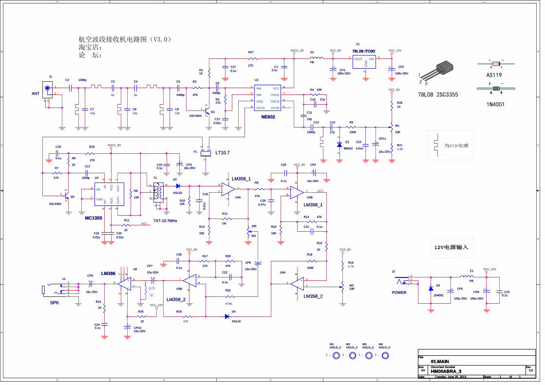
Circuit principle
Antenna to receive signals first enter a band-pass filter, the band-pass
filter function is to ensure that the 118 MHZ to 136 MHZ signal can be put into
2 sc3355 high, other signal is maximum attenuation. After filtering, the signal
amplified by the 25th sc3355 (2), and then enter the NE602 mixing, at the same
time NE602 inside a voltage-controlled oscillator, the frequency changes because
of the D1 junction capacitance, design covers about 120 MHZ to 150 MHZ.
Native intermediate frequency is 10.7 MHz, after NE602 mixing signal to 10.7 MHz ceramic filter, its function is to filter out irrelevant signals generated by mixing, and then the signal to do into Q2, finally gave MC1350 further intermediate frequency amplifier. MC1350 amplified signal, in the weeks after the T1 frequency selective, D2 for amplitude modulation signal envelope detection.Check out the audio signal after U4A and U5B, LM386 amplification for headphone output again.Among them, the AGC function performed by U4A and U4B, mute function by U5A, U5B to cooperate to complete.
Component selection
All less than 1000 pf the capacitors for high frequency of ceramics, greater than 1 uf capacitance for aluminum electrolytic capacitors, all resistance is a quarter w 5% fixed resistance.
Production debugging
Control circuit diagram and the identity of the PCB mounting of all
components. General compliance installation sequence of low to high. Checked
everything is in order, after turn on the juice and the power of positive and
negative polarity must not be wrong. Insert the walkman headphones headphone
socket, should be white noise could be heard. Touch one end of the detector
diode, audio headphones get bigger noise description function is normal. To the
antenna connected to a soft line of 60 cm, will hear a noise significantly
larger, mean channel essentially normal.
Because of all the inductance walked straight line on the PCB, and high precision, no need to be adjusted. Such as near no carrier signal, advice from C5 to 60 centimeters or so at the end of the software, then short circuit R21, so the vibration of the coverage has reached around 100-150 MHZ, judge machine can listen to the local FM signal.
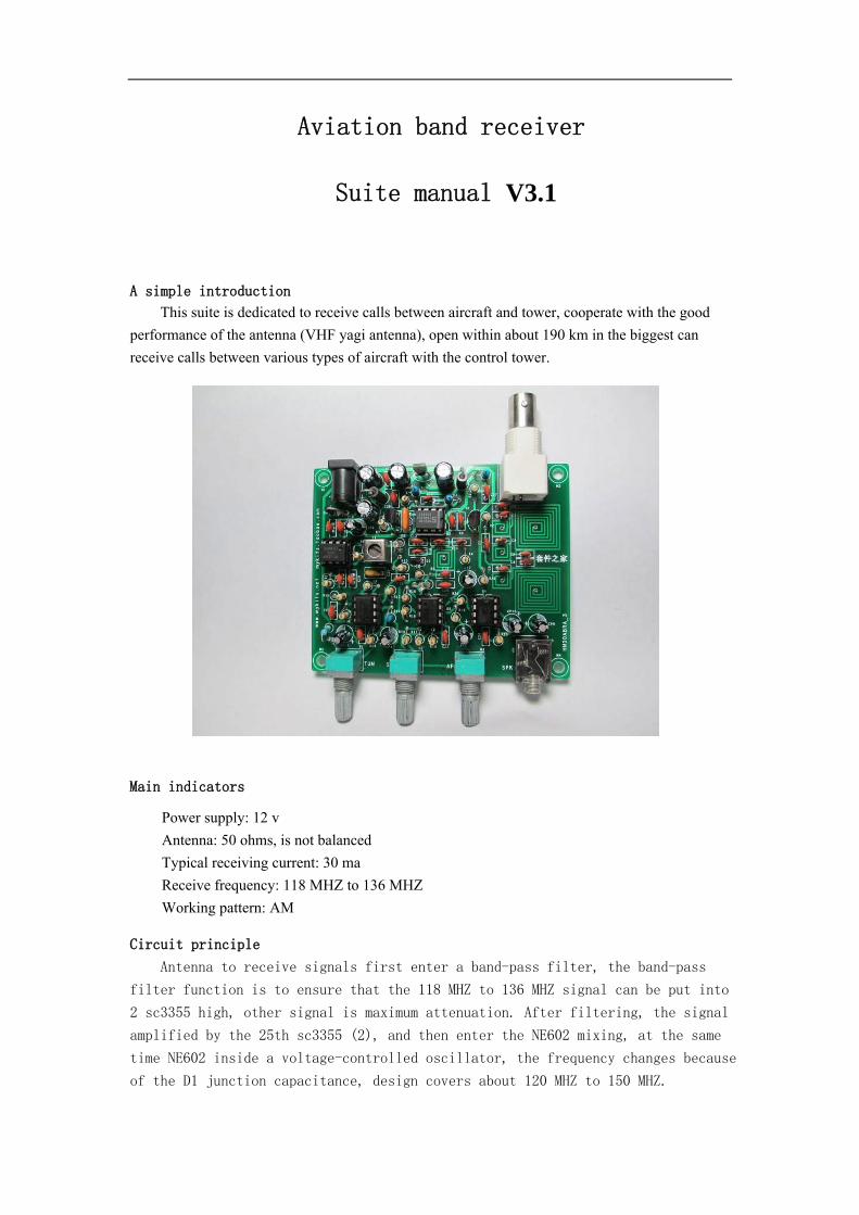
Native function knob from left to right are: frequency control, noise
threshold adjustment, volume adjustment, clockwise. Headphone socket on the
right.
Method of use
For VHF are close to a straight line transmission, therefore VHF
communication cannot be obscured, listening to the tower signal more need to
pay attention to it, close to the airport in a plane is apart from the ground
height when there are several hundred to several thousand meters high, so the
signal can cover a distance. In order to better effect, it is recommended to
use external high antenna, such as a quarter wavelength (60 cm) of GP antenna,
yagi antenna or using better VHF paragraph. In a word, need according to the
practical environment, appropriate cooperates antenna, can obtain good result!
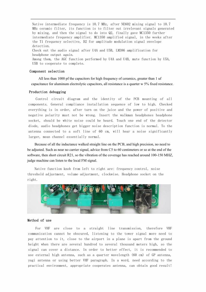
For primary fans, it is recommended to use GP antenna or yagi antenna.
Below is GP antenna, GPS antenna is short for flat ground antenna, the antenna,
also known as vertical ground antenna is a kind of common vertical polarization
omnidirectional antennas. It consists of a vertical level of radiation
oscillator and 3-4 root extension of the oscillator. A few metal rod with a M,
made simple.
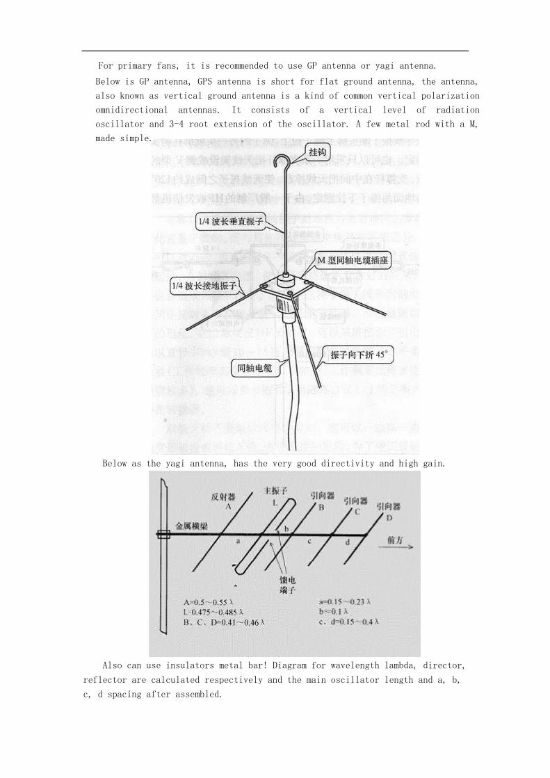
Below as the yagi antenna, has the very good directivity and high gain.
Also can use insulators metal bar! Diagram for wavelength lambda, director,
reflector are calculated respectively and the main oscillator length and a, b,
c, d spacing after assembled.
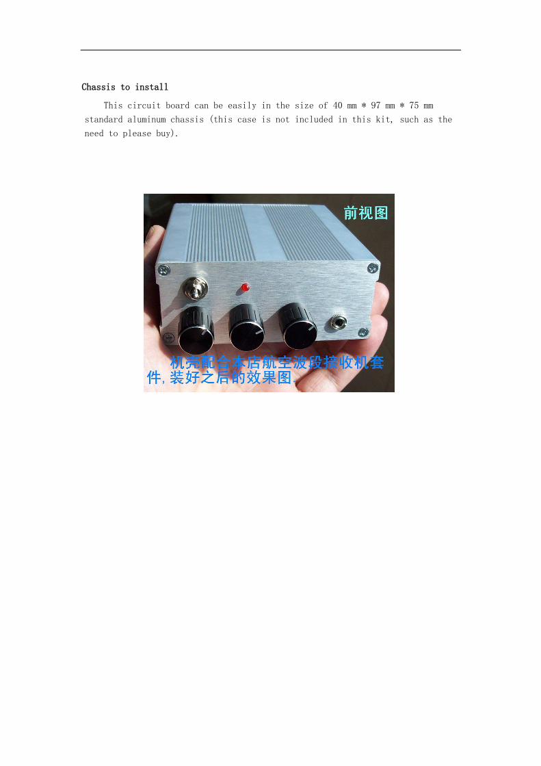
Chassis to install
This circuit board can be easily in the size of 40 mm * 97 mm * 75 mm
standard aluminum chassis (this case is not included in this kit, such as the
need to please buy).
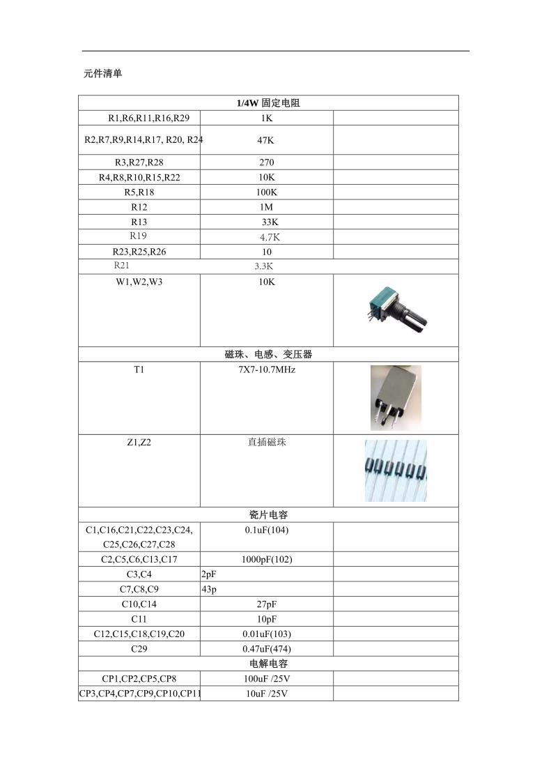
元件清单
1/4W 固定电阻
R1,R6,R11,R16,R29 1K
R2,R7,R9,R14,R17, R20, R24 47K
R3,R27,R28 270
R4,R8,R10,R15,R22 10K
R5,R18 100K
R12 1M
R13 33K
R23,R25,R26 10
W1,W2,W3 10K
磁珠、电感、变压器
T1 7X7-10.7MHz
Z1,Z2 直插磁珠
瓷片电容
C1,C16,C21,C22,C23,C24,
C25,C26,C27,C28
0.1uF(104)
C2,C5,C6,C13,C17 1000pF(102)
C3,C4 2pFC7,C8,C9 43pC10,C14 27pF
C11 10pF
C12,C15,C18,C19,C20 0.01uF(103)
C29 0.47uF(474)
电解电容
CP1,CP2,CP5,CP8 100uF /25V
CP3,CP4,CP7,CP9,CP10,CP11 10uF /25V
R19 4.7K
R21 3.3K
CT has been welded in T1 weeks inside, no need to install.
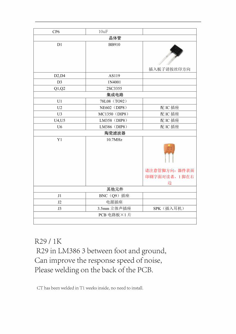
CP6
晶体管
D1 BB910
插入板子请按丝印方向
D2,D4 AS119
D3 1N4001
Q1,Q2 2SC3355
集成电路
U1 78L08(TO92)
U2 NE602(DIP8) 配 IC 插座
U3 MC1350(DIP8) 配 IC 插座
U4,U5 LM358(DIP8) 配 IC 插座
U6 LM386(DIP8) 配 IC 插座
陶瓷滤波器
Y1 10.7MHz
请注意管脚方向:器件表面
印刷字面对读者,1 脚在右
边
其他元件
J1 BNC(Q9)插座
J2 电源插座
J3 3.5mm 立体声插座 SPK(插入耳机)
PCB 电路板×1 片
10uF
R29 / 1K R29 in LM386 3 between foot and ground,Can improve the response speed of noise,Please welding on the back of the PCB.
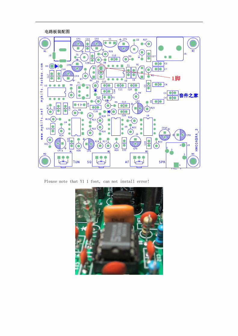
电路板装配图
Please note that Y1 1 foot, can not install error!
5
5
4
4
3
3
2
2
1
1
D D
C C
B B
A A
AGC
AGC
VCC_12VAVCC_8V
AVCC_8V
VCC_12V
VCC_12V
VCC_8V
VCC_8V
VCC_8V VCC_8V
VCC_8V
Title
Size Document Number Rev
Date: Sheet of
HM00ABRA_3 3.0
01.MAIN
A3
1 1Tuesday, June 25, 2013
Title
Size Document Number Rev
Date: Sheet of
HM00ABRA_3 3.0
01.MAIN
A3
1 1Tuesday, June 25, 2013
Title
Size Document Number Rev
Date: Sheet of
HM00ABRA_3 3.0
01.MAIN
A3
1 1Tuesday, June 25, 2013
航空波段接收机电路图(V3.0)淘宝店:论 坛:
为PCB电感
78L08 2SC3355
AS119
1N4001
12V电源输入
M2HOLD_0M2HOLD_0
1
+
CP9
10u /25V
+
CP9
10u /25V
C10.1u
C10.1u
-
+
U5B
LM358_2
-
+
U5B
LM358_2
5
67
84
C2 1000pC2 1000p
C11
10p
C11
10p
+ CP5
100u /25V
+ CP5
100u /25VR23
10
R23
10
C120.01uC12
0.01u
R11KR11K
R15
10K
R15
10K
U3
MC1350
U3
MC1350
OU
T-1
VC
C2
NK3 IN-
4
AG
C5
IN+
6
GND7
OU
T+8
J2
POWER
J2
POWER
123
R7
47K
R7
47K
C290.47u
C290.47u
+
CP7
10u /25V
+
CP7
10u /25V
C13
1000p
C13
1000p
M3HOLD_0M3HOLD_0
1
R12
1M
R12
1M
-
+
U5A
LM358_2
-
+
U5A
LM358_2
3
21
84
R17
47K
R17
47K
+CP3
10u /25V
+CP3
10u /25V
R11
1K
R11
1K
C240.1uC240.1u
C9C943p
R2
47K
R2
47K
R6
1K
R6
1K
R14 47KR14 47K
U1
78L08 /TO92
U1
78L08 /TO92
VIN 3
GN
D2
VOUT1
M4HOLD_0M4HOLD_0
1
+CP8
100u /25V
+CP8
100u /25V
C25
0.1u
C25
0.1u
C8C843p
T1
7X7-10.7MHz
T1
7X7-10.7MHz
61
2
43
78
C6
1000p
C6
1000p
C3C3
2p
C270.1uC270.1u
W210KW210K
W1
10K
W1
10K
R3270R3270 R26
10R2610
C160.1uC160.1u
+CP6
10u /25V
+CP6
10u /25V
Q12SC3355
Q12SC3355
32
1
M1HOLD_0M1HOLD_0
1
R22R22
470K
U2
NE602
U2
NE602
GND3
OUTA4
VCC 8
OSCB 6
INA1
INB2 OSCE 7
OUTB 5C7C743p
R4 10KR4 10K
R25
10
R25
10
C4C4
2p
J1
ANT
J1
ANT
1
2
34
C230.1u
C230.1u
R21R213.3K
R27
270
R27
270
R24R24
47K
R8
10K
R8
10K
+CP1
100u /25V
+CP1
100u /25V
-
+
U4B
LM358_1
-
+
U4B
LM358_1
5
67
84
C190.01uC19
0.01u
Z1
FB
Z1
FB
C28
0.1u
C28
0.1u
J3
SPK
J3
SPK1
2
5
34
+ CP2
100u /25V
+ CP2
100u /25V
C10 27pC10 27p
C26
0.1u
C26
0.1u
R19R194.7K
D3
1N4001
D3
1N4001
C18
0.01
u
C18
0.01
uR1010KR1010K
+CP11
10u /25V
+CP11
10u /25V
D2
AS119
D2
AS119
R20
47K
R20
47K
D4
AS119
D4
AS119
C17
1000p
C17
1000p
R18
100K
R18
100K
-
+
U4A
LM358_1
-
+
U4A
LM358_13
21
84
C5
1000p
C5
1000p
Z2
FB
Z2
FB
R16
1K
R16
1K
Q2
2SC3355
Q2
2SC3355
32
1
C15
0.01u
C15
0.01u
C22
0.1u
C22
0.1u+
-
U6
LM386+
-
U6
LM3863
25
61
4
87
+CP1010u /25V
+CP1010u /25V
R9
47K
R9
47K
R5
100K
R5
100K
Y1 LT10.7Y1 LT10.7
132
C21 0.1uC21 0.1u
C14
27p
C14
27p
W3
10K
W3
10K
R28
270
R28
270
D1
BB910
D1
BB910
12
R13
33K
R13
33KC200.01uC200.01u
+
CP4
10u /25V
+
CP4
10u /25V
R29
1K


![KD-T408 / KD-T406 / KD-T401 · Data Size: B6L (182 mm x 128 mm) Book Size: B6L (182 mm x 128 mm) ENGLISH ไทย B5A-2618-00 [M] KD-T408 / KD-T406 / KD-T401 CD RECEIVER INSTRUCTION](https://img.pdfslide.tips/doc/110x75/6050c5e673dc316d426208ad/kd-t408-kd-t406-kd-data-size-b6l-182-mm-x-128-mm-book-size-b6l-182-mm.jpg)


![CD RECEIVER INSTRUCTION MANUAL CD - Quale Scegliere€¦ · Data Size: B6L (182 mm x 128 mm) Book Size: B6L (182 mm x 128 mm) ENGLISH ไทย B5A-0826-00 [M] KW-R520 CD RECEIVER](https://img.pdfslide.tips/doc/110x75/5f914c78e8fc45644a09c7aa/cd-receiver-instruction-manual-cd-quale-scegliere-data-size-b6l-182-mm-x-128.jpg)

![KD-X241 / KD-X141 - JVCKenwoodData Size: B6L (182 mm x 128 mm) Book Size: B6L (182 mm x 128 mm) ENGLISH ไทย B5A-1355-00 [M] KD-X241 / KD-X141 DIGITAL MEDIA RECEIVER INSTRUCTION](https://img.pdfslide.tips/doc/110x75/5e3e31678e405a63f96e123b/kd-x241-kd-x141-data-size-b6l-182-mm-x-128-mm-book-size-b6l-182-mm-x-128.jpg)