Embed Size (px)
Citation preview

www.picaxe.com/products/axe101
AXE101 Cyberpet Kit © Revolution Education Ltd 2002-2016 v3.0 May be copied for educational use. 1
AXE101 PICAXE-08M2 Cyberpet Kit
The Cyberpet project uses a PICAXE-08M2 microcontroller with two LEDs as the pets ‘eyes’ and a piezo sounder as a ‘voice’ for the pet. The project also uses a switch so that the pet can respond to ‘touch’, and a Light Dependent Resistor (LDR) so that the pet can tell whether it is light or dark.
C.0 output LED eye C.1 input LDR C.2 output piezo sounder C.3 input push switch C.4 output LED eye
Remember not to confuse the chip ‘leg’ number with the input/output pin number! For the full datasheet please see www.picaxe.com/docs/axe101.pdf

www.picaxe.com/products/axe101
AXE101 Cyberpet Kit © Revolution Education Ltd 2002-2016 v3.0 May be copied for educational use. 2
1.0 Kit Contents
3 R1,R2,R6 RES-10K 10k resistor (brown black orange gold)
1 R3 RES-22K 22k resistor (red red orange gold)
2 R4,R5 RES-330 330R resistor (orange orange brown gold)
1 LK1 wire link (use offcut resistor leg)
2 LED1,LED2 LED001 5mm red LED
1 PZ SPE003* uncased piezo sounder
1 LDR SEN002 miniature light dependent resistor
1 SW1 SEN030 miniature 6mm switch
1 IC1 ICH008 8 pin IC socket
1 IC1 AXE007M2 PICAXE-08M2 microcontroller
1 CT1 CON039 PICAXE download 3.5mm socket
1 BT1 BAT016 battery clip
1 BT1 BAT013 4.5V (3xAA) battery box
1 PCB Cyberpet printed circuit board
* The cased piezo SPE001 may be purchased separately if preferred to uncased SPE003.
Loose wire (not supplied, if connecting LEDs and LDR by wires)
Tools required:
soldering iron and solder, side cutters
For the full please datasheet see www.picaxe.com/docs/axe101.pdf

www.picaxe.com/products/axe101
AXE101 Cyberpet Kit © Revolution Education Ltd 2002-2016 v3.0 May be copied for educational use. 3
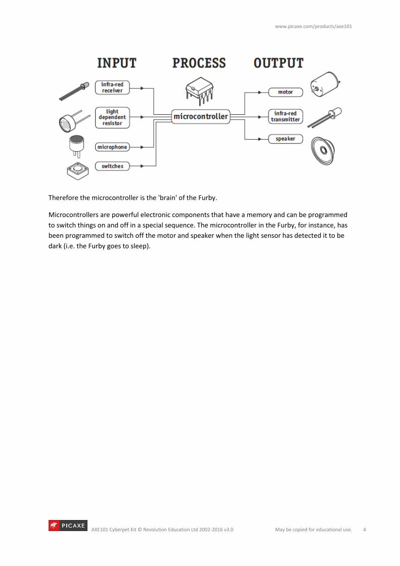
2.0 What is a microcontroller?
A microcontroller is often described as a 'computer-on-a-chip'.
It can be used as an ‘electronic brain’ to control a product, toy
or machine.
The microcontroller is an integrated circuit ("chip") that
contains memory (to store the program), a processor (to
process and carry out the program) and input/ output pins (to
connect switches, sensors and output devices like motors).
Microcontrollers are purchased 'blank' and then programmed with a specific control program. This
program is written on a computer and then 'downloaded' into the microcontroller chip. Once
programmed the microcontroller is built into a product to make the product more intelligent and
easier to use.
2.1 Example use of a microcontroller.
In most toy shops there are now lots of intelligent
'toys' available. These toys can move, make noises and
respond to being touched or being placed in a dark
place.
An example of one such toy is the 'Furby' made by
Tiger Electronics. The Furby has a microcontroller as
its electronic 'brain' and reacts (to being touched or
being placed in the dark) by moving or making sounds.
The Furby reacts to the outside world by sensors and
switches. It has a push switch on its front and back, a
microswitch in its mouth and a light sensor (LDR)
between its eyes. There is also a microphone on its
side so that it can detect sounds.
The Furby's movement is provided by an electric
motor. It also has a speaker to generate sounds and
an infra-red LED so that it can send signals to other
Furby's that might be nearby.
www.picaxe.com/products/axe101
AXE101 Cyberpet Kit © Revolution Education Ltd 2002-2016 v3.0 May be copied for educational use. 4
Therefore the microcontroller is the 'brain' of the Furby.
Microcontrollers are powerful electronic components that have a memory and can be programmed
to switch things on and off in a special sequence. The microcontroller in the Furby, for instance, has
been programmed to switch off the motor and speaker when the light sensor has detected it to be
dark (i.e. the Furby goes to sleep).

www.picaxe.com/products/axe101
AXE101 Cyberpet Kit © Revolution Education Ltd 2002-2016 v3.0 May be copied for educational use. 5
3.0 Cyberpet Design Brief
Design and make an electronic ‘cyberpet’ toy. The cyberpet must be programmed with its own
‘personality’ so that it reacts in a unique way.
3.1 Design Specification Points
1) The design will use a PICAXE-08M2 microcontroller as its brain.
2) The design will include LED eyes, a piezo sounder to generate noises and could also
optionally use a motor to generate movement.
3) The design will be able to react to touch and changes in light level.
4) The cyberpet can be designed as a flat ‘2-dimensional’ panel or as a full ‘3- dimensional’
creature.
3.2 Block Diagram
The block diagram for your cyberpet may look like this:
3.3 Designing Your Own Cyberpet
Your cyberpet can be any shape or size you choose. You may like to design the ‘face’ of the pet using
a computer graphics program or by drawing by hand. You could scan in a picture of a living animal,
or design a completely new ‘robot’ animal.
Things to think about:
The electronic components will need to be mounted inside (or underneath) your cyberpet. The LEDs
and LDR will need to poke through holes (normally 5mm wide, although LEDs are also available in
other sizes). You should also think carefully about where the batteries are going to be stored and
where the wires are going to be connected.

www.picaxe.com/products/axe101
AXE101 Cyberpet Kit © Revolution Education Ltd 2002-2016 v3.0 May be copied for educational use. 6
3.4 Assembly
How you build your Cyberpet PCB will depend on the
shape and size of your design. You may solder all the
components directly onto the board, or you may
connect some of the components (e.g. the LEDs, the
LDR and the switch) by longer pieces of wire so they
can be fitted inside your Cyberpet. These instructions
presume you are soldering all the components directly
on the board. The instructions are identical if you are
using longer wires to join some components, although
you must be even more careful you get the wires
around the correct way on the LEDs
1) Place the three 10k (brown black orange gold) resistors in position. Bend the legs to hold the
resistors in position and then solder.
2) Place the 22k (red red orange gold) and two 330 (orange orange brown gold) resistors in
position. Bend the legs to hold the resistors in position and then solder.
3) Using an off cut resistor leg, make a wire loop over the letters PX marked beside the 330R
resistors. Solder in position. (Ignore the hole above the holes marked CF).
4) Push the PICAXE stereo download socket onto the PCB and make sure it clicks into position
(so that it lies flat on the board). Solder the five metal square contacts (the five round
plastic support post holes do not have to be soldered). Do not worry if the solder joins on
the two metal contacts either side of the socket as they are supposed to be joined anyway.
5) Push the IC socket into position. Make sure the notch at one end points up towards the
stereo download socket. Fold the legs over to hold the socket in position and then solder.
6) Solder the LDR and two LEDs into position. Make sure the flat on one side of the LED aligns
with the flat marked on the PCB.
7) Solder the switch in position (note that it only fits one way around). If using wires solder one
wire into either one of the two bottom holes and the other wire into either one of the two
top holes.
8) Thread the battery clip down through the large hole by the letters AXE. Thread it back up
through the large hole by the letters 101. Then solder the black wire in the hole marked 0V
and the red wire in the hole marked V+.
9) Use half a sticky pad to stick the SPE003 piezo sounder (brass side) to the top of the PCB.
Thread the wires down through the hole below LED1 and back up through the hole marked
PZ. Solder the red wire into the bottom hole and the black wire into the top hole. It does not
matter if the red wire solder joint joins to pin5 of the IC socket as they are supposed to join
anyway. However the black wire should NOT join pin 6 of the IC socket. If using the optional
SPE001 cased piezo instead simply solder it directly in place (either way around).
10) Carefully check the board to make sure there are no missed joints or accidental solder
bridges.
The board is designed to be used with a 4.5V (3xAA) battery pack. Do NOT use a 9V PP3 battery.
revolution
V+ 0V 1
CF
PX cyberget

www.picaxe.com/products/axe101
AXE101 Cyberpet Kit © Revolution Education Ltd 2002-2016 v3.0 May be copied for educational use. 7
3.5 Testing your circuit.
Step 1 - Check the solder joints.
Check that all the joints are connected to both the pad and the wire, and that the wire is held firmly
so that it does not ‘wobble’ when pulled. Also check that the solder does not accidentally bridge
between two pads. This is most likely to happen on the LEDs, the LDR and on the piezo. On the
stereo socket the two square pads close together on each side can be joined as they are already
joined by a track on the board. However they must not be joined to the central round hole.
Step 2 - Check the components.
1) Check that the black battery clip wire is in the hole marked ‘0V’ and the red battery clip wire
is in the hole marked ‘V+’
2) Check that the PICAXE-08M2 chip is in the socket correctly, with the dent (showing pin1)
closest to the stereo download socket.
3) Check that the flat edge of the LED is connected to the correct hole on the PCB.
4) Make sure you have not forgotten the wire link over the holes marked PX at the bottom left
of the board.
5) Make sure the brass side of the piezo is stuck down with a sticky pad.
6) Check that the socket is correctly soldered, including the middle square pad which is often
forgotten by mistake.
Step 3 - Connect the battery.
Check the 3 AA batteries are in the battery box correctly. Connect the battery box to the battery
snap and put your finger on the PICAXE chip. If it starts to get hot remove the battery box
immediately as there is a problem – most likely that the chip or the battery snap wires are around
the wrong way.

www.picaxe.com/products/axe101
AXE101 Cyberpet Kit © Revolution Education Ltd 2002-2016 v3.0 May be copied for educational use. 8
4.0 Example PICAXE programs
PICAXE-08M2 Input / Output Connections
C.0 output LED eye C.1 input LDR C.2 output piezo sounder C.3 input push switch C.4 output LED eye
Examples are provided for Blockly, Flowchart and BASIC programming options.
To view the included samples files within ‘PICAXE Editor 6’ use the File>Open Samples menu and
select ‘AXE101 – Cyperpet’
www.picaxe.com/products/axe101
AXE101 Cyberpet Kit © Revolution Education Ltd 2002-2016 v3.0 May be copied for educational use. 9
4.1 Switching the LEDs on and off
4.1.0 What is an LED?
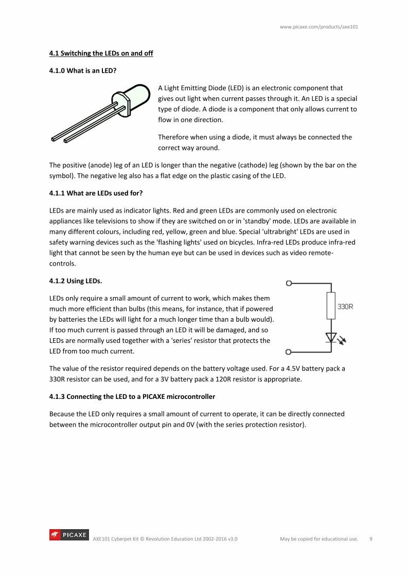
A Light Emitting Diode (LED) is an electronic component that
gives out light when current passes through it. An LED is a special
type of diode. A diode is a component that only allows current to
flow in one direction.
Therefore when using a diode, it must always be connected the
correct way around.
The positive (anode) leg of an LED is longer than the negative (cathode) leg (shown by the bar on the
symbol). The negative leg also has a flat edge on the plastic casing of the LED.
4.1.1 What are LEDs used for?
LEDs are mainly used as indicator lights. Red and green LEDs are commonly used on electronic
appliances like televisions to show if they are switched on or in 'standby' mode. LEDs are available in
many different colours, including red, yellow, green and blue. Special 'ultrabright' LEDs are used in
safety warning devices such as the 'flashing lights' used on bicycles. Infra-red LEDs produce infra-red
light that cannot be seen by the human eye but can be used in devices such as video remote-
controls.
4.1.2 Using LEDs.
LEDs only require a small amount of current to work, which makes them
much more efficient than bulbs (this means, for instance, that if powered
by batteries the LEDs will light for a much longer time than a bulb would).
If too much current is passed through an LED it will be damaged, and so
LEDs are normally used together with a 'series' resistor that protects the
LED from too much current.
The value of the resistor required depends on the battery voltage used. For a 4.5V battery pack a
330R resistor can be used, and for a 3V battery pack a 120R resistor is appropriate.
4.1.3 Connecting the LED to a PICAXE microcontroller
Because the LED only requires a small amount of current to operate, it can be directly connected
between the microcontroller output pin and 0V (with the series protection resistor).

www.picaxe.com/products/axe101
AXE101 Cyberpet Kit © Revolution Education Ltd 2002-2016 v3.0 May be copied for educational use. 10
4.1.4 Testing the LEDs
This project board has LEDs on: Output C.0
Output C.4
Therefore make sure the correct pin number is selected within each PICAXE command.
The following program will flash one LED on and off every second.
Blockly Flowchart
BASIC
do
high C.0 ; LED on
pause 1000 ; wait 1 second
low C.0 ; LED off
pause 1000 ; wait 1 second
loop
If the LED does not work check:
1. the LED is connected the correct way around
2. the correct resistor is used
3. the correct output pin number is being used in the program
4. all the solder joints are good

www.picaxe.com/products/axe101
AXE101 Cyberpet Kit © Revolution Education Ltd 2002-2016 v3.0 May be copied for educational use. 11
4.2 Using the push switch
4.2.0 What are switches?
A ‘switch’ is a type of digital sensor, a sensor that can only be ‘on’ or ‘off’. Switches detect
movement.
There are a large number of different types of switches e.g.:
push switches that detect a momentary 'push'
micro-switches with long levers that detect small movements tilt-switches that detect jolting
reed-switches that detect a magnet being moved
4.2.1 What are switches used for?
Push switches are commonly used on device like keypads. Micro-switches are used in burglar alarms
to detect if the cover is removed from the alarm box. Reed switches are used to detect doors and
windows being opened and tilt switches are often used to detect movement in devices such as toys,
hair-dryers and tool-box alarms.
4.2.2 Using switches with a PICAXE microcontroller
A switch is often used with a resistor as shown in the diagram. The value of
the resistor is not that important, but a 10k resistor is often used. When the
switch is 'open' the 10k resistor connects the microcontroller input pin
down to 0V, which gives an ‘off’ (logic level 0) 0V signal to the
microcontroller input pin.
When the switch is activated, the input pin is connected to the positive
battery supply (V+). This provides an ‘on’ (logic level 1) signal to the
microcontroller.
10k

www.picaxe.com/products/axe101
AXE101 Cyberpet Kit © Revolution Education Ltd 2002-2016 v3.0 May be copied for educational use. 12
4.2.3 Testing the switch
This project board has a switch on: Input pinC.3
Therefore make sure the correct pin number is selected within each PICAXE command.
After connecting the switch it can be tested by a simple program like this. This program will switch
an output on and off according to whether the switch is pushed or not.
Blockly Flowchart
BASIC
do
if pinC.3 = 1 then ; test pinC.3
high C.0 ; LED on
else
low C.0 ; LED off
end if
loop

www.picaxe.com/products/axe101
AXE101 Cyberpet Kit © Revolution Education Ltd 2002-2016 v3.0 May be copied for educational use. 13
4.3 Using the LDR
4.3.0 What is an LDR?
A Light Dependent Resistor (LDR) is a special type of resistor that reacts to changes in light level. The
resistance of the LDR changes as different amounts of light fall on the top 'window' of the device.
This allows electronic circuits to measure changes in light level.
4.3.1 What are LDRs used for?
LDRs are used in automatic street lamps to switch them on at night and off during the day. They are
also used within many alarm and toys to measure light levels.
The LDR is a type of analogue sensor. An analogue sensor measures a continuous signal such as light,
temperature or position (rather than a digital on-off signal like a switch). The analogue sensor
provides a varying voltage signal. This voltage signal can be represented by a number in the range 0
and 255 (e.g. very dark = 0, bright light = 255).

www.picaxe.com/products/axe101
AXE101 Cyberpet Kit © Revolution Education Ltd 2002-2016 v3.0 May be copied for educational use. 14
4.3.2 Using an LDR with a PICAXE microcontroller.
The electronic circuit for using the LDR is known as a ‘potential divider’. A
suitable value for the lower resistor is 10k. The voltage at the centre
position of the potential divider varies as the resistance of the LDR changes
in different light conditions.
The microcontroller contains an 'analogue to digital converter (ADC)' which
converts the varying voltage signal into a number between 0 and 255. This
number can then be stored in a variable and compared against a desired
‘threshold point’.
4.2.3 Testing the LDR
This project board has an LDR on: Input C.1
Therefore make sure the correct pin number is selected within each PICAXE command.
This program will switch an output on and off according to whether the light level is greater than
100. But how do you know 100 is the correct threshold value to use? See the next section…
Blockly Flowchart
BASIC
symbol varA = b1
do
readadc C.1, varA ; read ADC value on C.1
if varA > 100 then ; test value
high C.0 ; LED on
else
low C.0 ; LED off
end if
loop

www.picaxe.com/products/axe101
AXE101 Cyberpet Kit © Revolution Education Ltd 2002-2016 v3.0 May be copied for educational use. 15
4.2.3 Calibrating the analogue sensor
When using an analogue sensor you may not always know what the correct threshold value to use.
The threshold value is normally a number that is half way between the lowest (darkest) and highest
(brightest) analogue values possible.
Fortunately the PICAXE system has a special ‘debug’ command which can transmit the value of the
variable to the computer screen. Using this command you can therefore run an experiment – for
instance using your hand to cover the LDR to calculate the highest and lowest possible values.
The threshold value to use is the value that is half way between these maximum and minimum
values.
To try this out modify the previous program by inserting an extra ‘debug’ command (found in the
Serial Commands section) after the readadc command.
Blockly Flowchart
BASIC
symbol varA = b1
do
readadc C.1, varA ; read ADC value on C.1
debug ; send value to computer
if varA > 100 then ; test value
high C.0 ; LED on
else
low C.0 ; LED off
end if
loop

www.picaxe.com/products/axe101
AXE101 Cyberpet Kit © Revolution Education Ltd 2002-2016 v3.0 May be copied for educational use. 16
After downloading this new program open the Debug panel on the computer screen. The Debug
panel will then show the value of the light reading.
In PICAXE Editor 6 the debug panel is found in the Code Explorer on the right hand side of the
screen.
In the Blockly Chrome App the Debug panel can be opened from the PICAXE menu.
Once the experiment is complete select a new threshold value half way between the maximum and
minimum values found. Then modify the original program to use this value rather than the value 100
that was originally used.

www.picaxe.com/products/axe101
AXE101 Cyberpet Kit © Revolution Education Ltd 2002-2016 v3.0 May be copied for educational use. 17
4.4 Using the Piezo Sounder
4.4.0 What is a piezo transducer?
A piezo transducer is a low-cost 'mini-speaker' that can used to make
sounds. The sound that the piezo makes can be changed by altering the
electronic signals provided by the microcontroller.
4.4.1 Where are piezos used for?
Piezos are used in many different consumer goods to provide 'feedback' to the user. A good example
is a vending machine which will 'beep' whenever a keypad switch is pressed to select a drink or
snack. The 'beep' provides the user with feedback to tell them their switch push has been successful.
Uncased piezos are also often used in musical birthday cards to play a tune when the card is opened.
4.4.2 What is the difference between a piezo and a buzzer?
A buzzer contains a small electronic circuit that generates the electronic signal
needed to make a noise. Therefore when a buzzer is connected to a battery it
will always make the same sound. A piezo does not contain this circuit, and so
therefore needs an external signal. This signal can be supplied by the output pin of a microcontroller.
A piezo also requires less current to operate and so will last longer in battery powered circuits.
4.4.3 Using piezos.
A piezo is very simple to connect. Simply connect the red wire to the
microcontroller output pin and the black wire to 0V (ground).
Note that the cheapest piezos do not have a plastic casing to them. In this case
it is necessary to mount the piezo on a piece of board (with a sticky pad) to
create a noise that can be heard. The board acts as a 'sound-box' to amplify
the sound made by the piezo. For instance on a musical birthday card it is
actually the whole card that vibrates and acts as the speaker, not just the
piezo!
More expensive piezos have a round plastic case that acts as this sound-box.
An example of this type of device is order code SPE001.
Make sure the sticky pad is stuck on the correct side of the piezo (the brass
side without the wires!).

www.picaxe.com/products/axe101
AXE101 Cyberpet Kit © Revolution Education Ltd 2002-2016 v3.0 May be copied for educational use. 18
4.4.4 Testing the Piezo
This project board has a piezo on: Output C.2
Therefore make sure the correct pin number is selected within each PICAXE command.
This program will play the tune ‘Happy Birthday’ on the piezo sounder when the switch is pressed.
Blockly Flowchart
BASIC
do
if pinC.3 = 1 then
play 0, 0
endif
loop
Other commands that can used with the piezo sounder are ‘sound’ to create beep type noises and
‘tune’ to play other user defined RTTTL ringtone tunes. See the main PICAXE manuals for more
details about these two extra commands.

www.picaxe.com/products/axe101
AXE101 Cyberpet Kit © Revolution Education Ltd 2002-2016 v3.0 May be copied for educational use. 19
5.0 On-Screen Simulation
Blockly and PE6 both contain a simulation feature that allows you
to ‘try out’ your programs on screen. The simulated chip leg
changes colour when outputs are switched on and off, and you can
also click on an input pin to change it from on to off and vice versa.
To start the simulation click the ‘run’ button in the Simulation
tab/panel.
The speed that the simulation runs can be adjusted by the
simulation speed slider (in PE6 this is at the bottom right of the
screen).
To simulate an analogue input like an LDR value right click over the
pin and use the ‘radial slider’ to change the analogue value used
within the program.
In PE6 it is also possible to change the default simulation
layout (08M2 chip) to a picture of the project board
instead. To do this change the simulation setting within
the Workspace Explorer as shown here.

www.picaxe.com/products/axe101
AXE101 Cyberpet Kit © Revolution Education Ltd 2002-2016 v3.0 May be copied for educational use. 20
In PE6 it is also possible to ‘connect’ to a larger simulation model of the project kit. To do this select
Simulate > Connect > Connect to software simulation > AXE101 Cyberpet
When the program is simulated you can then interact with the larger simulation model.

www.picaxe.com/products/axe101
AXE101 Cyberpet Kit © Revolution Education Ltd 2002-2016 v3.0 May be copied for educational use. 21
6.0 More Complex Example
This example waits until the switch is pressed, and then checks the light value. If it is dark one tune is
played, if bright a different tune is played.
In PE6 use File > Open Samples > AXE101 Cyberpet to open these sample files.
Blockly
Flowchart

www.picaxe.com/products/axe101
AXE101 Cyberpet Kit © Revolution Education Ltd 2002-2016 v3.0 May be copied for educational use. 22
BASIC
symbol varA = b1
do
if pinC.3 = 1 then
readadc C.1, varA
if varA < 128 then
play 0, 0
else
play 1, 0
endif
endif
loop

www.picaxe.com/products/axe101
AXE101 Cyberpet Kit © Revolution Education Ltd 2002-2016 v3.0 May be copied for educational use. 23
7.0 Circuit Diagram
Download circuit:
Note that output C.0 is connected to both the LED and to the download circuit, so the LED will flicker
during the programming process.