Embed Size (px)
Citation preview

4GN50K GEAR HEAD
取扱説明書 はじめにAXUシリーズは、薄型・高トルクのブラシレスDCモーターと小型・コンパクトなコントロールユニットを採用したブラシレスモーターユニットです。コントロールユニットだけでモーターの速度設定、運転/停止の操作ができ、速度を頻繁に変更しない搬送機器、攪拌機などの速度制御用途に最適です。単相100-115V50/60Hz、単相200-230V 50/60Hz、三相200-230V 50/60Hzの3種類があります。ギヤヘッド(別売り) が直結できる歯切りシャフトタイプと高速回転が必要な用途に最適な丸シャフトタイプを用意しました。
お買い上げいただきありがとうございます。この取扱説明書には、製品の取り扱いかたや安全上の注意事項を示しています。取扱説明書をよくお読みになり、製品を安全にお使いください。お読みになったあとは、いつでも見られるところに必ず保管してください。
図のモーターは歯切りシャフトタイプのモーターに、別売りのギヤヘッドを組み付けています。
AXUシリーズ
この製品は、一般的な産業機器の機器組み込み用として設計されています。その他の用途には使用しないでください。この警告を無視した結果生じた損害の補償については、当社は一切その責任を負いませんので、あらかじめご了承ください。
SPEED CONTROL UNIT
AXUD25APOWER
ALARM
HIGH
LOW
STAND-BY
RUN
ORIENTAL MOTOR
English version follows Japanese version.
ブラシレスモーターユニット
HM-5027-8

モーターの回転部(出力軸)に、カバーを設
けてください。けがの原因になります。モーター(歯切りシャフト)とギヤヘッドを組
み付けるときは、モーターとギヤヘッドの
間に指などをはさまないようにしてください。
けがの原因になります。モーターまたはギヤヘッド付きモーターを装
置に設置するときは、装置とモーターまた
はギヤヘッドとの間に指などをはさまないよ
うにしてください。けがの原因になります。モーターとコントロールユニットは、指定さ
れた組み合わせで使用してください。火災
の原因になります。装置の故障や動作の異常が発生したとき
は、装置全体が安全な方向へはたらくよう
非常停止装置、または非常停止回路を外
部に設置してください。けがの原因になり
ます。異常が発生したときは、ただちに運転を停止
してコントロールユニットの電源を切ってく
ださい。火災・感電・けがの原因になります。モーターは、正常な運転状態でも、表面温
度が70を超えることがあります。運転中
のモーターに接近できるときは、図の警告ラ
ベルをはっきり見える位置に貼ってください。
やけどの原因になります。
コントロールユニットのスロースタート/スロ
ーダウン時間設定器は、絶縁された+の精
密ドライバで設定してください。感電の原
因になります。絶縁抵抗測定、絶縁耐圧試験を行なうとき
は、端子に触れないでください。感電の原
因になります。モーター、コントロールユニットを廃棄する
ときは、産業廃棄物として処理してください。
2
AXU Series
安全上のご注意製品の取り扱いは、適切な資格を有する人が行なってください。お使いになる前に、「安全上のご注意」をよくお読みのうえ、製品を正しくお使いください。ここに示した注意事項は、製品を安全に正しくお使いいただき、お客様や他の人々への危害や損傷を未然に防止するためのものです。内容をよく理解してから製品をお使いください。
警告
爆発性雰囲気、引火性ガスの雰囲気、水
のかかる場所、可燃物のそばでは使用しな
いでください。火災・感電・けがの原因にな
ります。設置、接続、運転・操作、点検・故障診断
の作業は、適切な資格を有する人が行なっ
てください。火災・感電・けがの原因になり
ます。通電状態で移動、設置、接続、点検の作業
をしないでください。電源を切ってから作業
をしてください。感電の原因になります。保護機能がはたらいたときは、電源を切り、
原因を取り除いた後で電源を再投入してく
ださい。原因を取り除かずにモーターの運
転を続けたときは、モーター、コントロール
ユニットが誤動作して、けが・装置破損の原
因になります。モーター、コントロールユニットはクラスI機器のみに使用してください。感電の原因に
なります。モーター、コントロールユニットを機器に設
置するときは、接地してください。感電の原
因になります。コントロールユニットの電源入力電圧は、定
格範囲を必ず守ってください。火災・感電
の原因になります。接続は接続例にもとづき、確実に行なって
ください。火災・感電の原因になります。モーターケーブル、延長ケーブル(別売り)を
加工・改造しないでください。ケーブルの被
覆を剥離して、シールド線を接地したり、触
れたりしないでください。感電・漏電遮断器
が動作する原因になります。接続終了後は、電源接続端子、入出力信号
接続端子の端子カバーを取り付けてくださ
い。火災・感電の原因になります。
ケーブルを無理に曲げたり、引っ張ったり、
はさみ込んだりしないでください。火災・感
電の原因になります。停電したときは、コントロールユニットの電
源を切ってください。停電復旧時にモータ
ーが突然起動して、けが・装置破損の原因
になります。昇降装置には、使用しないでください。コン
トロールユニットの保護機能がはたらくと
モーターは停止します。可動部が落下して、
けが・装置破損の原因になります。電源を切った直後(30秒以内)は、コントロ
ールユニットの端子台に触れないでくださ
い。感電の原因になります。モーター、ギヤヘッド、コントロールユニット
を分解・改造しないでください。感電・けが
の原因になります。内部の点検や修理は、
お買い上げになった支店または営業所に連
絡してください。
モーター、コントロールユニットの仕様値を
超えて使用しないでください。感電・けが・
装置破損の原因になります。コントロールユニットの開口部に物を入れ
ないでください。火災・感電・けがの原因に
なります。運転中および停止後しばらくの間は、モー
ター、コントロールユニットに触れないでく
ださい。高温のため、やけどの原因になり
ます。モーター出力軸、モーターケーブルを持た
ないでください。けがの原因になります。モーター、コントロールユニットの周囲には、
可燃物を置かないでください。火災・やけど
の原因になります。
注意
警告ラベル
警告 この警告事項に反した取り扱いをすると、死亡または重傷を負う場合がある内容を示して
います。
注意 この注意事項に反した取り扱いをすると、傷害を負うまたは物的損害が発生する場合があ
る内容を示しています。
重要 製品を正しくお使いいただくために、お客様に必ず守っていただきたい事項を本文中の
関連する取り扱い項目に記載しています。

3
AXU Series
パッケージを開けたら、次のものがすべて揃っているか、確認してください。もし、不足している場合や破損している場合には、お買い求めの支店、営業所までご連絡ください。
お買い求めの製品のユニット品名は、パッケージのラベルに記載された品名で確認してください。モーターおよびコントロールユニットの品名は、それぞれ製品の銘板に記載された品名で確認してください。ユニット品名に対するモーターおよびコントロールユニットの組み合わせは、下表のようになっています。
製品の確認
歯切りシャフトタイプ
モーター、コントロールユニットの組み合わせ モーター、コントロールユニットの組み合わせ
単相100-115V用
ユニット品名
AXU210A-GNAXU425A-GNAXU540A-GNAXU590A-GU
モーター品名
AXUM210-GNAXUM425-GNAXUM540-GNAXUM590-GU
コントロールユニット品名
AXUD10AAXUD25AAXUD40AAXUD90A
単相200-230V用
ユニット品名
AXU210C-GNAXU425C-GNAXU540C-GNAXU590C-GU
モーター品名
AXUM210-GNAXUM425-GNAXUM540-GNAXUM590-GU
コントロールユニット品名
AXUD10CAXUD25CAXUD40CAXUD90C
三相200-230V用
ユニット品名
AXU210S-GNAXU425S-GNAXU540S-GNAXU590S-GU
モーター品名
AXUM210-GNAXUM425-GNAXUM540-GNAXUM590-GU
コントロールユニット品名
AXUD10SAXUD25SAXUD40SAXUD90S
単相100-115V用
ユニット品名
AXU210A-AAXU425A-AAXU540A-AAXU590A-A
モーター品名
AXUM210-AAXUM425-AAXUM540-AAXUM590-A
コントロールユニット品名
AXUD10AAXUD25AAXUD40AAXUD90A
単相200-230V用
ユニット品名
AXU210C-AAXU425C-AAXU540C-AAXU590C-A
モーター品名
AXUM210-AAXUM425-AAXUM540-AAXUM590-A
コントロールユニット品名
AXUD10CAXUD25CAXUD40CAXUD90C
三相200-230V用
ユニット品名
AXU210S-AAXU425S-AAXU540S-AAXU590S-A
モーター品名
AXUM210-AAXUM425-AAXUM540-AAXUM590-A
コントロールユニット品名
AXUD10SAXUD25SAXUD40SAXUD90S
POWER
ALARM
HIGH
LOW
STAND-BY
RUN
ORIENTAL MOTOR
SPEED CONTROL UNITAXUD25A
モーター(歯切りシャフト) 1台 コントロールユニット1台
シートパッキン1枚
コントロールユニット取り付けねじ(M3)セット(ねじ、ナット、ワッシャ各4個)
短絡片 1個
電源ケーブル1本
取扱説明書 1部
4GN50K GEAR HEAD
取扱説明書 はじめにAXUシリーズは、薄型・高トルクのブラシレスDCモーターと小型・コンパクトなコントロールユニットを採用したブラシレスモーターユニットです。コントロールユニットだけでモーターの速度設定、運転/停止の操作ができ、速度を頻繁に変更しない搬送機器、攪拌機などの速度制御用途に最適です。単相100-115V50/60Hz、単相200-230V 50/60Hz、三相200-230V 50/60Hzの3種類があります。ギヤヘッド(別売り) が直結できる歯切りシャフトタイプと高速回転が必要な用途に最適な丸シャフトタイプを用意しました。
お買い上げいただきありがとうございます。この取扱説明書には、製品の取り扱いかたや安全上の注意事項を示しています。取扱説明書をよくお読みになり、製品を安全にお使いください。お読みになったあとは、いつでも見られるところに必ず保管してください。
図のモーターは歯切りシャフトタイプのモーターに、別売りのギヤヘッドを組み付けています。
AXUシリーズ
この製品は、一般的な産業機器の機器組み込み用として設計されています。その他の用途には使用しないでください。この警告を無視した結果生じた損害の補償については、当社は一切その責任を負いませんので、あらかじめご了承ください。
SPEED CONTROL UNIT
AXUD25APOWER
ALARM
HIGH
LOW
STAND-BY
RUN
ORIENTAL MOTOR
English version follows Japanese version.
ブラシレスモーターユニット
HM-5027-8
POWER
ALARM
HIGH
LOW
STAND-BY
RUN
ORIENTAL MOTOR
SPEED CONTROL UNITAXUD25A
モーター(丸シャフト) 1台 コントロールユニット1台
コントロールユニット取り付けねじ(M3)セット(ねじ、ナット、ワッシャ各4個)
短絡片 1個
丸シャフトタイプ
取扱説明書 1部
4GN50K GEAR HEAD
取扱説明書 はじめにAXUシリーズは、薄型・高トルクのブラシレスDCモーターと小型・コンパクトなコントロールユニットを採用したブラシレスモーターユニットです。コントロールユニットだけでモーターの速度設定、運転/停止の操作ができ、速度を頻繁に変更しない搬送機器、攪拌機などの速度制御用途に最適です。単相100-115V50/60Hz、単相200-230V 50/60Hz、三相200-230V 50/60Hzの3種類があります。ギヤヘッド(別売り) が直結できる歯切りシャフトタイプと高速回転が必要な用途に最適な丸シャフトタイプを用意しました。
お買い上げいただきありがとうございます。この取扱説明書には、製品の取り扱いかたや安全上の注意事項を示しています。取扱説明書をよくお読みになり、製品を安全にお使いください。お読みになったあとは、いつでも見られるところに必ず保管してください。
図のモーターは歯切りシャフトタイプのモーターに、別売りのギヤヘッドを組み付けています。
AXUシリーズ
この製品は、一般的な産業機器の機器組み込み用として設計されています。その他の用途には使用しないでください。この警告を無視した結果生じた損害の補償については、当社は一切その責任を負いませんので、あらかじめご了承ください。
SPEED CONTROL UNIT
AXUD25APOWER
ALARM
HIGH
LOW
STAND-BY
RUN
ORIENTAL MOTOR
English version follows Japanese version.
ブラシレスモーターユニット
HM-5027-8
電源ケーブル1本
認定機関 規格ファイルNo.
UL E208200
規格対応品
UL E171462
規格対応品
安全規格・CEマーキングモーターおよびコントロールユニットは下記の規格に従って設計、検査を行なっています。
EN50178規格で要求されるEMC測定は、モーターおよびコントロールユニット単体では行なっていません。最終製品として組み込んだ状態でEMCテストを行なってください。
EN50178規格で要求される過電圧保護試験は行なっていません。最終製品として組み込んだ状態で試験を実施してください。
適用規格
UL1950CSA C22.2 No.950EN60950EN60034-1EN60034-5UL508C∗CSA C22.2 No.14EN60950EN50178
CEマーキング
低電圧指令
∗ UL規格(UL508C)は、Maximum Surrounding Air Temperature 40で認定されています。
設置条件過電圧カテゴリーIII、汚染度2、クラス I機器(適用規格 EN規格)機器によって汚染度3の規定値が要求される場合は、コントロールユニットをIP54相当のキャビネットに収納してください。
対 象
モーター
コントロールユニット
重要

4
AXU Series
各部の名称と機能
POWER
ALARM
HIGH
LOW
STAND-BY
RUN
ORIENTAL MOTOR
SPEED CONTROL UNITAXUD25A
RUN/STAND-BYスイッチ 「RUN」側に切り替えるとCW入力 またはCCW入力がONした方向に モーターが運転し、「STAND-BY」側に するとモーターが停止します。 「STAND-BY」では運転できません。
取付穴 (2か所)
速度設定器 モーターの運転速度を 設定します。 ツマミを時計方向に まわすと速度が速くなります。
POWER LED (緑色) 通電時に点灯します。
ALARM LED (赤色) 保護機能がはたらいた ときに、点滅または 点灯します。
コントロールユニット前面 コントロールユニット背面
モーターケーブル
コネクタ
保護接地端子
グリスシール チューブ
ALARMOUT
SPEEDOUT
CCW
COM
CW
MOTOR
NC
L
N
入出力信号接続端子 入出力信号ケーブルを 接続し、外部コントローラ などと接続します。
保護接地端子 保護接地用ケーブルを 接続します。
モーターコネクタ モーターケーブルを 接続します。
電源接続端子 電源ケーブルを 接続します。
保護接地端子 保護接地用ケーブルを 接続します。 ※ 図は25W 歯切りシャフトタイプです。
設置場所モーター(ギヤヘッド)、コントロールユニットは機器組み込み用に設計、製造されています。風通しがよく、点検が容易な次のような場所に設置してください。屋内使用周囲温度 モーター: 0~+50(凍結しないこと)コントロールユニット: 0~+40(凍結しないこと)UL、CSA規格では、0~+40で認定されています。使用周囲湿度 85%以下(結露しないこと)爆発性雰囲気や有害な雰囲気のないところ直射日光があたらないところほこり、導電性微粉がかからないところ水、油その他の液体がかからないところ連続的な振動や過度の衝撃が加わらないところ放射線、磁場がなく真空でないところ過電圧カテゴリーIII、汚染度2、クラス I機器(適用規格 EN規格)機器によって汚染度3の規定値が要求される場合は、コントロールユニットをIP54相当のキャビネットに収納してください。
4か所の取付穴を使用して、設置する金属板との間にすき間がないように、4本のねじ・ナット(付属していません)で固定してください。
設 置
1
4か所の取付穴を使用して、設置する金属板との間にすき間がないように、ギヤヘッドに付属の4本の取り付けねじで固定してください。
モーター(ギヤヘッド)の設置モーター(ギヤヘッド)は耐振動性にすぐれ、熱伝導効果が高い平滑な金属板に設置してください。モーターケース温度は90以下で使用してください。
10W、25Wタイプの歯切りシャフト部に付いているグリスシールチューブ(白)は、取り外さずにそのままギヤヘッドと組み付けてください。グリスシールチューブを取り外すとギヤヘッドのグリスがモーター内部に流れ込み、モーターが破損する原因になります。
モーターとギヤヘッドを組み付けるときは、それぞれのインロー部を案内として、モーターの歯切り部をギヤヘッドの側板やギヤに強く当てないよう、ギヤヘッドをゆっくり左右にまわしながら行なってください。
ギヤヘッド取付面にあるボス部は、座ぐりまたは貫通加工されたインロー受けにはめ込んでください。
モーター取付面に付属のシートパッキンを取り付け、ギヤヘッドを組み付けます。組み付けできるギヤヘッドの歯切りタイプは、10W、25W、40WタイプはGNタイプ、90WタイプはGUタイプです。
2
重要
モーター取付面にあるインローは、座ぐりまたは貫通加工されたインロー受けにはめ込んでください。
丸シャフトタイプは、モーターケース温度が90以下になるように、以下のサイズの金属板に取り付けてください。
締め付けトルク
歯切りシャフトタイプ
丸シャフトタイプ
ユニット品名中のには、電圧仕様を表すAまたはCまたはSが入ります。( )内のギヤヘッド品名中のには、減速比の数字が入ります。
ユニット品名中のには、電圧仕様を表すAまたはCまたはSが入ります。
ユニット品名
AXU210-GN
AXU425-GN
AXU540-GN
AXU590-GU(5GUKBの場合)
AXU590-GU(5GUKBHの場合)
締め付けトルク
1.8N・m
3.8N・m
6.4N・m
6.4N・m
15.5N・m
ボルトの呼び
M4
M5
M6
M6
M8
締め付けトルク
ユニット品名中のには、電圧仕様を表すAまたはCまたはSが入ります。
ユニット品名
AXU210-A
AXU425-A
AXU540-A
AXU590-A
締め付けトルク
1.8N・m
6.4N・m
15.5N・m
15.5N・m
ボルトの呼び
M4
M6
M8
M8
ユニット品名
AXU210-A
AXU425-A
AXU540-A
AXU590-A
厚さ
5mm
放熱板の大きさ
135mm×135mm
165mm×165mm
200mm×200mm
200mm×200mm
シートパッキン
モーターインロー グリスシールチューブ
ギヤヘッドインロー
ボス部 モーター
ギヤヘッド(別売り)
重要
重要

5
AXU Series
モーター(ギヤヘッド)と負荷を結合するときは、心出し、ベルトのテンション、プーリーの平行度などに注意してください。また、カップリングやプーリーの締め付けねじは確実に締め付けてください。
モーター出力軸またはギヤ出力軸にカップリングやプーリーなどを取り付けるときは、出力軸や軸受けに損傷を与えないでください。
モーター(ギヤヘッド)出力軸を改造したり、機械加工をしないでください。ベアリングに損傷を与え、モーターやギヤヘッドが破損することがあります。
負荷の取り付けモーターまたはギヤヘッドに負荷を取り付けるときは、モーター出力軸またはギヤヘッド出力軸と負荷の軸中心線を揃えてください。
2GNタイプのギヤヘッド出力軸および丸シャフトタイプのモーター出力軸は、フライスカット加工がされています。フライスカット部にダブルポイントねじなどを使用して、負荷が空転しないよう確実に固定してください。
4GN, 5GN, 5GUタイプのギヤヘッド出力軸は、キーみぞ加工がされています。取り付ける負荷側にもキーみぞ加工をして、ギヤヘッドに付属のキーで固定してください。
カップリング直結のときモーター(ギヤヘッド)出力軸と負荷の軸中心線を一直線にしてください。
ベルト連結のときモーター(ギヤヘッド)出力軸と負荷の軸を平行にし、両プーリーの中心を結ぶ線と軸を直角にしてください。
ギヤ連結のときモーター(ギヤヘッド)出力軸とギヤ軸を平行にし、ギヤ歯面の中心に正しくかみ合わせてください。
コントロールユニットの設置設置方向コントロールユニットは空気の対流による放熱を前提として設計されています。コントロールユニットを筐体内へ設置するときは、コントロールユニットに2か所ある放熱口のうち1か所が必ず下側にくるようにして設置してください。
設置方法コントロールユニットは耐振動性にすぐれた平滑な金属板に設置してください。
角穴をあけて取り付けるとき
コントロールユニットの取付穴を使用して、金属板との間にすき間がないように、2本のねじ(M4)とナットで固定してください。
コントロールユニットは、筐体および筐体内の他の機器と水平方向は25mm以上、垂直方向は50mm以上離して設置してください。
コントロールユニットの周囲には、発熱量やノイズが大きい機器を設置しないでください。
コントロールユニットの周囲温度が40を超える場合には、換気条件を見直すか、コントロールユニットをファンで強制冷却してください。
MOTOR
NC
AC
W
OM
CCW
PEEDUT
ARMUT
放熱口
底面にも放熱口が あります。
POWER
ALARM
HIGH
LOW
STAND-BY
RUN
ORIENTAL MOTOR
SPEED CONTROL UNITAXUD25A
M4ねじ 2本を用意 してください。
2-φ4.5
81+
1
90±
0.2
53+1
パネル加工図
0
0
ねじの締め付けトルクは0.7N·m未満としてください。0.7N·mを超えるトルクで締め付けると、コントロールユニットが破損する場合があります。
付属の取り付けねじセットを使用してコントロールユニットを取り付けるとき
8ページ上の「フロントパネルの外し方」の要領でフロントパネルを外して取り付けます。
STAND-BY
RUNORIENTAL MOTOR
SPEED CONTROL UNIT
AXUD25A
HIGH
LOW
POWER
ALARM
取り付けねじセット(付属)
M4ねじ 2本を用意 してください。
パネル加工図 (厚さ2mm以下)
2-φ7.5
4-φ3.5
90±
0.2
23±
0.2
31.5±
0.2
24±
0.2
12±
0.2
14.6±0.2
15±0.2
50±0.2
取付板
φ15
φ15
φ7.5φ20
φ3.
5
φ6.
590°
(断面図A)
(断面図A)
重 要
重要
重要

6
AXU Series
EMC指令に対する設置・配線方法
EMC指令に対する設置・配線方法AXUシリーズから周辺の制御システム機器へのEMIと、AXUシリーズのEMSに対し有効な対策をとらなければ、機械装置の機能に重大な障害を招くおそれがあります。AXUシリーズは、次の設置・配線方法を施すことで、EMC指令(適用規格は前述によります)への適合が可能になります。
ACラインフィルタの接続コントロールユニットで発生したノイズが電源ラインを介して外部へ伝ぱんするのを防止するため、AC入力ラインにはACラインフィルタを接続してください。ACラインフィルタには、右上表の製品または相当品を接続してください。
この製品は、「モーター、コントロールユニットの設置・配線例」でEMC測定を行なっています。必ずこの「EMC指令に対する設置・配線方法」をご覧になり、お客様の装置に組み込んだ状態で、EMC測定を行なってください。
はじめにEMC指令(89/336/EEC、92/31EEC)
AXUシリーズは、機器組み込み用の部品として設計・製造されています。EMC指令では、この製品が組み込まれたお客様の機械装置での適合が要求されます。これからご紹介するモーター/コントロールユニットの設置・配線方法は、お客様の機械装置のEMC指令への適合に有効な基本的な設置・配線方法について説明したものです。最終的な機械装置のEMCへの適合性は、モーター/コントロールユニットと一緒に使用される他の制御システム機器、電気部品の構成、配線、配置状態、危険度などによって変わってきますので、お客様ご自身で機械装置のEMC試験を行なって確認していただく必要があります。
適応規格EMI
Emission Tests EN61000-6-4Radiated Emission Test EN55011Conducted Emission Test EN55011
EMSImmunity Tests EN61000-6-2Electrostatic Discharge Immunity Test IEC61000-4-2Radiation Field Immunity Test IEC61000-4-3Fast Transient/Burst Immunity Test IEC61000-4-4Surge Immunity Test IEC61000-4-5Conductive Noise Immunity Test IEC61000-4-6Power Frequency MagneticField Immunity Test IEC61000-4-8Voltage Dip Immunity Test IEC61000-4-11Voltage Interruption Immunity Test IEC61000-4-11
モーターケーブルの接続モーターケーブルを延長するときは、別売りの延長ケーブルを使用してください。最大で10.5mまで延長できます。
信号ケーブルの配線コントロールユニットの信号ケーブルには、AWG28(0.09mm2)以上のシールドケーブルを使用して、できるだけ短く配線してください。シールドケーブルの接地には、金属製のケーブルクランプなど、シールドケーブルの全周と接触できるクランプを使用してください。ケーブルクランプは、シールドケーブルのできるだけ先端部分に取り付け、図のように適切な接地ポイントに接地してください。
ACラインフィルタは、できるだけコントロールユニットの近くに取り付け、入力ケーブルと出力ケーブルは筐体の盤面から浮かないように、ケーブルクランプなどを使用して確実に固定してください。ACラインフィルタの接地端子は、できるだけ太く、最短距離で接地ポイントに接地してください。
なお、AC入力側のケーブル(AWG22:0.34mm2
以上)と ACラインフィルタの出力ケーブル(AWG22:0.34mm2以上)は並行して配線しないでください。並行して配線すると、筐体内のノイズが浮遊容量を介して直接電源ケーブルに結合し、ACラインフィルタの効果が低減することがあります。
接地方法接地した箇所に電位差が生じないよう、コントロールユニット、モーター、およびACラインフィルタを接地するケーブルは、できるだけ太く、最短距離で接地ポイントに接地してください。接地ポイントには広く、太く、均一な導電面を使用してください。
コントロールユニットの接地コントロールユニット背面の保護接地端子を接地してください。接地方法については、「電源の接続」(P.7 )を参照してください。
モーターの接地モーターケーブルの保護接地端子を使って接地してください。接地方法については、「モーターの接続」(P.7)を参照してください。
モーター、コントロールユニットの設置・配線例
モーター
コントロールユニット
FG
ケーブル クランプ
信号ケーブル(2m)ACライン フィルタ
PE
ケーブル クランプ
グランドパネル
電源ケーブル
モーターケーブル(10.5m)
PE
PE
PE
PE
(シールドケーブル)
TDK株式会社
EPCOS
Schaffner Electronik AG
Tyco Electronics CORCOM
三相200-230V
-
-
FN251-8/07
-
単相100-115V単相200-230V
ZAG2210-11S
B84112-B-B110
FN2330Y-10-06FN2310X-10-06
10ESK1
シールドケーブル
ケーブルクランプ
設置・配線についての注意事項 モーター/コントロールユニットと周辺の制御システム機器のアース間に電位差が生じないように、直接接地ポイントに接地してください。
リレーや電磁スイッチを一緒に使用するときは、ACラインフィルタやCR回路でサージを吸収してください。
ケーブルは、長すぎて余った部分を巻いて束ねたりしないで、できるだけ短くしてください。
モーターケーブルや電源ケーブルなどの動力系のケーブルと信号系のケーブルは別々に分け、できるだけお互いを離して(例:100~200mm)配線してください。もし、動力系と信号系のケーブルが交差するときは、直角に交差させて配線してください。また、ACラインフィルタのAC入力側ケーブルと出力側ケーブルは、分離して配線してください。
静電気についての注意事項静電気によって、コントロールユニットが誤動作し
たり破損することがあります。コントロールユニッ
ト前面の速度設定器、スイッチを操作するとき以
外は、電源を投入した状態でコントロールユニッ
トに近づいたり、触れたりしないでください。
7
AXU Series
単相100ー115V ±10% 50/60Hz 単相200ー230V ±10% 50/60Hz
三相200ー230V ±10% 50/60Hz
{
NC
L
N 電源へ
{
NC
L
N 電源へ
L1
L2
L3
電源へ
{
接 続
モーターの接続モーターケーブルのコネクタをコントロールユニットのモーターコネクタ(MOTOR)に差し込みます。「カチッ」と音がするまで、差し込んで確実に接続してください。モーターとコントロールユニットの間を延長するときは、別売りの専用延長ケーブルを使用してください。最大で10.5mまで延長できます。延長ケーブルを使用する場合やモーターに直接手が触れられる場合は、モーターケーブルの保護接地用リード線(緑/黄、丸型端子付)を直接接地してください。保護接地用リード線の長さが足りないときは、AWG18(0.75mm2)以上の線径のリード線をモーターケーブルの緑/黄のリード線に接続し、できるだけ短い距離で接地してください。リード線は別途ご用意ください。また、別売りの専用延長ケーブルには保護接地用のリード線は付いていませんので、中継点で接地するか延長して接地してください。
電源の接続付属の電源ケーブルをコントロールユニットに接続します。赤と黒のリード線を電源接続端子へ、緑/黄のリード線を保護接地端子に接続します。付属の電源ケーブルを使用しない場合は、AWG22 (0.34mm2)以上の線径のケーブルを使用してください。保護接地ケーブルには、AWG18(0.75mm2)以上の線径のケーブルを使用してください。その際、接続には、絶縁付き丸型圧着端子を使用してください。
単相100-115Vのとき 単相200-230Vのとき
三相200-230Vのとき
φ3.2mm 以上
9mm 以上 6.2m
m 以下
〈適用圧着端子〉
W
OM
CCW
PEEDUT
ARM
UT
MOTOR
モーター接続 コネクタ
モーターケーブル
接地
端子カバー
電源へ
電源接続端子
端子カバー
入出力信号 接続端子 (接続には、 ツイストペア線 またはシールド されている線を 使用してください。) AC
付属ケーブル
モーター
コントロールユニット
1= SPEED出力周波数
T
SPEED出力周波数(Hz)モーター回転速度(r/min)= ×60
30
入出力信号ケーブルを延長するときは2m以内とし、ノイズの影響を抑えるためにもできるだけ短く配線してください。
入出力信号ケーブルは、電源ケーブルやモーターケーブルとは平行にしないで直交するように配線してください。
SPEED 出力モーターの運転に同期して、モーター出力軸1回転あたり30パルスのパルス信号(パルス幅:約0.5ms)を出力しています。SPEED出力の周波数を測定して、モーターの回転速度を算出することができます。
回転方向はモーターの出力軸側から見たときのモーター出力軸の回転方向です。ギヤヘッドの減速比によっては、ギヤ出力軸の回転方向がモーターの回転方向とは逆になることがあります。
入力信号と出力信号
入力回路(内部回路)
出力回路(内部回路)
ALARM 出力次のような場合に、コントロールユニットの保護機能がはたらいて、ALARM出力がOFF (Hレベル)になり、モーターを停止させます。このとき、LEDの点滅または点灯ではたらいた保護機能の内容を確認することができます。
※電源投入時にLEDが一瞬点灯しますが、異常ではありません。
次の保護機能がはたらくとLEDが点滅します
過負荷保護機能モーターに定格トルクを超える負荷が約5秒以上加わったときや、短時間の内にモーターの運転/停止や回転方向の切り替えを繰り返し行なったとき。
次の保護機能がはたらくとLEDが点灯します
欠相保護機能
モーター運転中に、モーターケーブル内のセンサ線が断線したとき、モーターの誤動作を防ぎます。(モーター停止中はアラーム信号を出力しません。)
過電圧保護機能
巻き下げ負荷運転や許容負荷慣性値を超えた負荷を駆動したとき。または、ドライバに印加される電圧がAC115VまたはAC230Vを約20%以上オーバーしたとき。
不足電圧保護機能
ドライバに印加される電圧がAC100VまたはAC200Vを約30%以上下回ったとき。
過速度保護機能
モーターの速度が2800r/minを超える異常な速度になったとき。
ALARM出力は、接続例のとおりに接続するとコントロールユニット正常時はON(Lレベル)に、アラーム時はOFF(Hレベル)となります。ALARM出力がOFF(Hレベル)になったときは、モーターの運転停止後にコントロールユニットの電源を切ってください。モーターケーブルに異常が無いときは、使用条件(負荷トルク、運転パターン、電源電圧など)の確認・再検討を行なってください。保護機能がはたらいた原因を取り除いた後で電源を再投入して、アラームをリセットしてください。電源再投入は、電源を切り30秒以上経過してから行なってください。
モーター出力軸の回転速度やギヤヘッド出力軸の減速された回転速度を表示、モニタするときは、別売りのデジタル表示型回転計SDM496をお買い求めください。
信号出力は、オープンコレクタ出力です。DC26.4V以下の電源を使用し、出力電流が10mAを超えないような制限抵抗(R)を接続してください。
CWCCW
COM
SPEEDALARM
COM
+14V
2kΩ
強化絶縁フォトカプラ
強化絶縁フォトカプラ
T0.5ms
SPEED OUTALARM OUT
COM
コントロールユニット コントローラ Vcc
R
電源の再投入や、モーターケーブルのコネクタを抜き差しするときは、電源を切って30秒以上経過してから行なってください。
重要
重要
重要
MOTORCW
COM
CCW
SPEEDOUT
ALARMOUT
NC
L
N
CW入力
CCW入力 COM
SPEED 出力 ALARM 出力

8
AXU Series
電源のON/OFFに、SSR(ソリッドステートリレー)を使用しないでください。モーター・コントロールユニットが破損することがあります。
クランプダイオードを内蔵したコントローラを使用するときは、電源のON/OFFの順序に気を付けてください。
電源ON :コントローラON→ コントロールユニットON
電源OFF:コントロールユニットOFF→ コントローラOFF
使用上のお願い右図のように接続したとき、コントロールユニットの電源を先にONしたり、コントロールユニットの電源をONにした状態でコントローラの電源をOFFすると図中の矢印のように電流がまわりこんで、モーターが運転することがあります。また、電源容量の違いで、同時に電源をONしたりOFFしたときにも、一時的にモーターが運転することがあります。電源は、必ずコントローラの方からONし、コントロールユニットの方からOFFしてください。
お客様のコントローラ コントロールユニット
CWCCW
COM
+14VVcc
運 転
AXUD25ASPEED CONTROL UNIT
ORIENTAL MOTOR
POWER
ALARM
HIGHLOW
STAND-BYRUN
速度設定器速度設定器のツマミを時計方向にまわすと、設定速度が速くなります。設定速度範囲は100~2000r/minとなっています。出荷時は0r/minに設定しています。
本体のRUN/STAND-BYスイッチで運転するとき(短絡片を使用)
RUN/STAND-BYスイッチを「RUN」側に切り替えるとモーターは回転します。「STAND-BY」側にもどすとモーターは停止します。
CW方向運転
CCW
COM
CW
CCW
COM
CW
CCW方向運転
RUN/STAND-BYスイッチは、電源のON/OFFスイッチではありません。モーターを長時間停止させるときは、コントロールユニットの電源をOFFにしてください。
電源の投入後、モーターの運転は1秒以上経過してから行なってください。1秒以下でRUNおよびCW(またはCCW)入力をONしても、モーターは回転しません。
CW
COM
CCW
OFFON
OFFON
CW
COM
CCW
付属の短絡片をCW-COM間またはCCW-COM間に接続します。短絡片は、他の用途には使用しないでください。
外部の信号で運転するときRUN/STAND-BYスイッチを「RUN」側に切り替えます。
小容量スイッチ、リレーのとき
リレーは、DC12V、5mAを開閉できる小容量接点タイプを使用してください。
STAND-BYRUN
STAND-BYRUN
CW(時計)方向運転CW入力がON(Lレベル)になるとモーターは時計方向へ回転します。CW入力がOFF(Hレベル)になるとモーターは停止します。
CCW(反時計)方向運転CCW入力がON(Lレベル)になるとモーターは反時計方向へ回転します。CCW入力がOFF(Hレベル)になるとモーターは停止します。
CW入力とCCW入力が同時にON(Lレベル)するとモーターは瞬時停止します。瞬時正逆転運転はできません。
CWCCW
回転方向は、短絡片の接続状態で決まります。
RUN/STAND-BYスイッチ
短絡片
短絡片
重要
タイミングチャート外部信号で運転する場合
トランジスタ出力タイプのコントローラのとき
CWおよびCCW入力信号は20ms以上の時間を確保してください。
重要
運転/回転方向切り替え 運転/瞬時停止/瞬時停止後の逆転
RUN/ STAND-BY スイッチ
CW入力
CCW入力
モーター動作
STAND-BY
RUN
ON OFF
OFF
ON
CW
CCW
0.5s※
CW入力とCCW入力が同時にONすると モーターは瞬時停止します。 ※瞬時停止後0.5s間は、逆転の運転信号 を入力してもモーターは運転しません。
20ms 以上
20ms 以上

AXU Series
モーター運転時に、速度設定や接続の誤りなどでモーターやコントロールユニットが正常に動作しないことがあります。モーターの運転操作が正常に行なえないときには、この項をご覧になって、適切な処置を行なってください。それでも正常に運転できないときは、最寄りのお客様ご相談センターにお問い合わせください。
故障の診断と処置
現 象 予想される原因 処 置
モーターが回転しない。 RUN/STAND-BYスイッチが「STAND-BY」側になっている。
CW入力とCCW入力がどちらもONになっている。
速度設定器を調整していない。
保護機能がはたらいている。(ALARM LEDが点滅または点灯している。)
RUN/STAND-BYスイッチを「RUN側」に切り替えて、CW入力またはCCW入力をONにしてください。
CW入力またはCCW入力のどちらか一方だけをONにしてください。
速度設定器を時計方向に少しまわしてください。
はたらいた保護機能に応じた原因の確認と対策を行なってください。
モーターが指定と逆方向にまわる。
CW入力とCCW入力の入力まちがいまたは接続不良。
ギヤヘッドの減速比によっては、モーターと逆方向にまわります。
正しい入力信号を入力してください。モーターはCW入力がLレベルのときCW方向に回転します。CCW入力がLレベルのときCCW方向に回転します。
ギヤヘッドの減速比によっては、モーターと逆方向に回転します。CW入力とCCW入力の操作を逆にしてください。[逆方向に回転する減速比]GNタイプ:
1/25、1/30、1/36GUタイプ:
1/12.5、1/15、1/18、1/75、1/90、1/100、1/120、1/150、1/180
モーターの動作が不安定。振動が大きい。
モーター(ギヤヘッド)の出力軸と負荷の軸心との心出しが合っていない。
モーターとギヤヘッドを正しく組み付けていない。
モーター(ギヤヘッド)出力軸と負荷軸の結合状態を確認してください。
モーターとギヤヘッドの組付状態および歯切りタイプを確認してください。
速度設定器のツマミを外しますフロントパネルとツマミの間にドライバなどを差し込み、軽く手前に引くとツマミが外れます。(ツマミの位置をLOW側一杯にまわしておきます。)
スロースタート/スローダウン時間の設定
STAND-BY
RUNORIENTAL MOTOR
SPEED CONTROL UNIT
AXUD25A
HIGH
LOW
POWER
ALARM
フロントパネル スロースタート/スローダウン 時間設定器
モーターは、起動時にスロースタートを行ない、停止時にはスローダウン停止となります。このスロースタート時間およびスローダウン時間を0.5~10秒(2000r/min 無負荷時)の範囲で設定できます。
フロントパネルの外し方
スロースタート/スローダウン時間設定器時計方向にまわすと時間が長くなります。設定時は絶縁された+の精密ドライバを使用してください。出荷時は最短時間に設定しています。
長い 短い STAND-BY
RUNORIENTAL MOTOR
SPEED CONTROL UNIT
AXUD25A
HIGH
LOW
POWER
ALARM
フロントパネルを外しますフロントパネルだけを持って手前に引くとフロントパネルが外れます。このとき、RUN/STAND-BYスイッチも一緒に外れます。なくさないでください。フロントパネルを取り付けるときは、逆の手順で行なってください。
9
絶縁抵抗測定、絶縁耐圧試験は、モーターとドライバそれぞれで行なってください。モーターとドライバを接続した状態で、絶縁抵抗測定、絶縁耐圧試験を行なうと、製品が破損するおそれがあります。
重要
この取扱説明書の一部または全部を無断で転載、複製することは、禁止されています。損傷や紛失などにより、取扱説明書が必要なときは、最寄りの支店または営業所に請求してください。
取扱説明書に記載されている情報、回路、機器、および装置の利用に関して産業財産権上の問題が生じても、当社は一切の責任を負いません。
製品の性能、仕様および外観は改良のため予告なく変更することがありますのでご了承ください。取扱説明書には正確な情報を記載するよう努めていますが、万一ご不審な点や誤り、記載もれなどにお気づきの点がありましたら、最寄りのお客様ご相談センターまでご連絡ください。
は、日本その他の国におけるオリエンタルモーター株式会社の登録商標または商標です。その他の製品名、会社名は各社の登録商標または商標です。この取扱説明書に記載の他社製品名は推奨を目的としたもので、それらの製品の性能を保証するものではありません。オリエンタルモーター株式会社は、他社製品の性能につきましては一切の責任を負いません。
© Copyright ORIENTAL MOTOR CO., LTD. 2008
This product is designed to be incorporated in the general in-dustrial machinery, and must not be used for other purposes.It should be noted in advance that ORIENTAL MOTOR CO.,LTD. is not responsible for any damages caused by ignoring thiswarning.
4GN50K GEAR HEAD
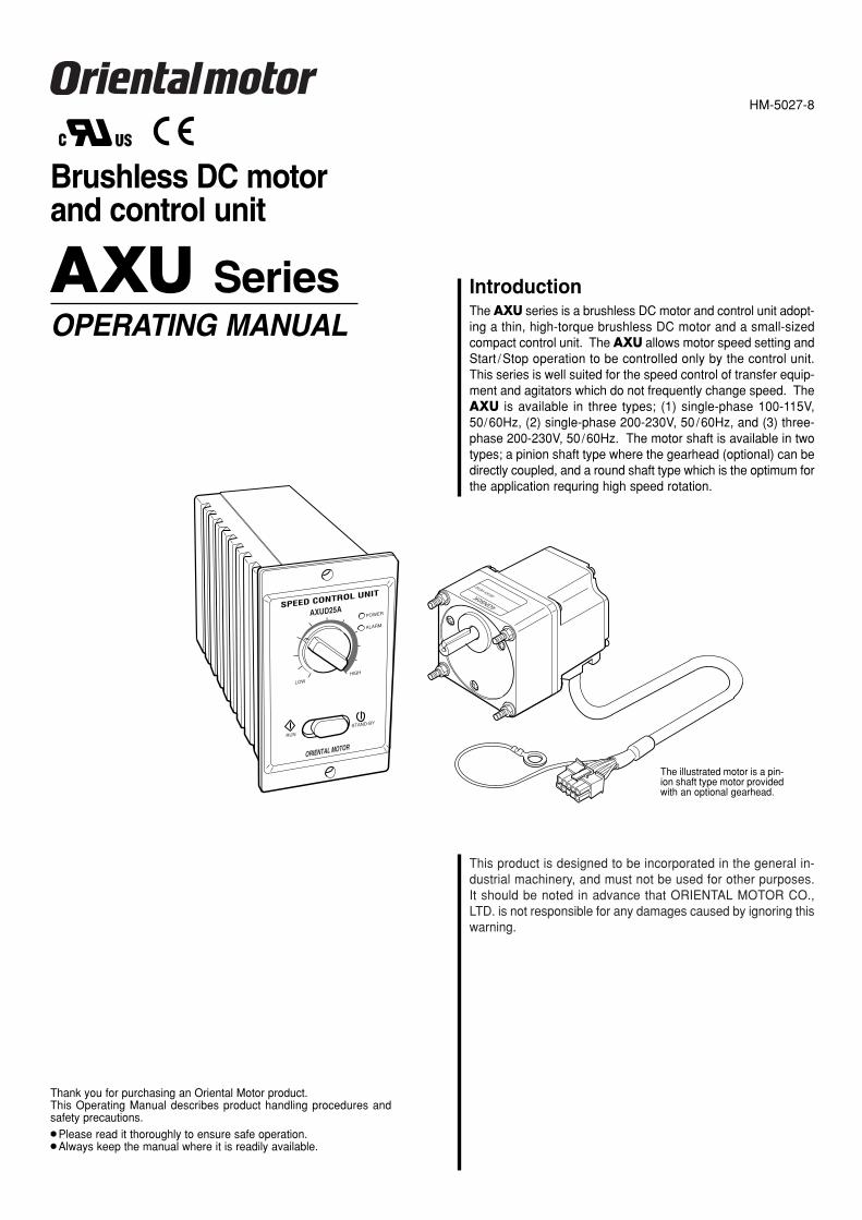
IntroductionThe AXU series is a brushless DC motor and control unit adopt-ing a thin, high-torque brushless DC motor and a small-sizedcompact control unit. The AXU allows motor speed setting andStart /Stop operation to be controlled only by the control unit.This series is well suited for the speed control of transfer equip-ment and agitators which do not frequently change speed. TheAXU is available in three types; (1) single-phase 100-115V,50/60Hz, (2) single-phase 200-230V, 50/60Hz, and (3) three-phase 200-230V, 50/60Hz. The motor shaft is available in twotypes; a pinion shaft type where the gearhead (optional) can bedirectly coupled, and a round shaft type which is the optimum forthe application requring high speed rotation.
Thank you for purchasing an Oriental Motor product.This Operating Manual describes product handling procedures andsafety precautions. Please read it thoroughly to ensure safe operation. Always keep the manual where it is readily available.
The illustrated motor is a pin-ion shaft type motor providedwith an optional gearhead.
SPEED CONTROL UNIT
AXUD25APOWER
ALARM
HIGH
LOW
STAND-BY
RUN
ORIENTAL MOTOR
AXU SeriesOPERATING MANUAL
HM-5027-8
Brushless DC motor and control unit

2
AXU Series
Safety precautions Only qualified personnel should work with the product.Use the product correctly after thoroughly reading the section “Safety precautions”.The precautions described below are intended to prevent danger or injury to the userand other personnel through safe, correct use of the product. Use the product onlyafter carefully reading and fully understanding these instructions.
Do not rework or modify the motor cable and extension cable(sold separately). Do not remove the sheath of the cable andthen ground or touch the shielded wire. This may cause elec-tric shock or trigger the ground fault interrupt circuit.
Be sure to install the terminal cover of the power connectionterminal and input/output signal connection terminal after mak-ing connections. Otherwise, fire and electric shock may occur.
Do not forcibly bend, pull or pinch the cable. Doing so may fireand electric shock.
Turn off the control unit power in the event of a power failure,or the motor may suddenly start when the power is restoredand may cause injury or damage to equipment.
Do not use it in a vertical application. When the control unitprotection function is activated, the motor will stop and mov-able portions may fall down to cause injury of the operator anddamage of the equipment.
Do not touch the terminals block of the control unit immediatelyafter the power is turned off (for a period of 30 seconds).Failure to do so may result in electric shock.
Do not disassemble or modify the motor, gearhead or controlunit. This may cause electric shock or injury. Refer all suchinternal inspections and repairs to the branch or sales officefrom which you purchased the product.
Do not use the motor and control unit beyond their specifica-tions, or electric shock, injury or damage to equipment may re-sult.
Keep objects out of the openings in the control unit, or elec-tric shock, injury or damage to equipment may result.
Do not touch the motor and control unit during operation or im-mediately after stopping. The surfaces are hot and may causea burn.
Do not hold the motor output shaft or motor cable. This maycause injury.
Keep the area around the motor and control unit free of com-bustible materials in order to prevent fire or a burn.
Provide a cover over the rotating parts (output shaft) of the mo-tor to prevent injury.
Do not allow your finger to be caught between the motor andgearhead when the motor (pinion shaft) and gearhead arecombined. This may cause injury.
Do not allow your finger to be caught between the equipmentand motor or gearhead when installing the motor or motor withgearhead on the equipment. This may cause injury.
Use a motor and control unit only in the specified combination.An incorrect combination may cause a fire.
Provide an emergency-stop device or emergency-stop circuitexternal to the equipment so that the entire equipment will op-erate safely in the event of a system failure or malfunction.Failure to do so may result in injury.
When an abnormality is noted, stop the operation immediate-ly and turn off the control unit power, or fire, electric shock orinjury may occur.
The motor’s surface temperature may exceed 70°C, even under normal operating conditions. If a motor is accessible during operation, post a warning label shown in the figure in a conspicuous position to prevent the risk of burns.
Use a insulated Phillips screwdriver for adjusting the slowstart /slowdown time setting potentiometer of control unit.Otherwise, electric shock may occur.
When testing the insulation resistance or dielectric strength, donot touch the terminal. Otherwise, electric shock may occur.
When disposing of the motor and control unit, treat them as or-dinary industrial waste.
The items under this heading contain important handling instructions that the user shouldobserve to ensure safe use of the product.
WarningHandling the product without observing the instructions that accompany a“Warning” symbol may result in serious injury or death.
CautionHandling the product without observing the instructions that accompany a“Caution” symbol may result in injury or property damage.
Do not use the product in explosive or corrosive environments,in the presence of flammable gases, locations subjected tosplashing water, or near combustibles. Doing so may result infire, electric shock or injury.
Assign qualified personnel the task of installing, wiring, oper-ating/controlling, inspecting and troubleshooting the product.Failure to do so may result in fire, electric shock or injury.
Do not transport, install the product, perform connections or in-spections when the power is on. Always turn the power off be-fore carrying out these operations. Failure to do so may resultin electric shock.
When the protection function is triggered, shut off the powerimmediately. Turn the power back on only after removing thecause. Continuing the operation without removing the causeof the problem may cause malfunction of the motor and con-trol unit, leading to injury or damage to equipment.
To prevent the risk of electric shock, use the motor and controlunit for class I equipment only.
When install the motor and control unit, ground them to pre-vent the risk of electric shock.
Keep the control unit’s input-power voltage within the specifiedrange to avoid fire and electric shock.
Connect the cables securely according to the wiring diagramin order to prevent fire and electric shock.
Warning
Caution
NOTE
Warning label

3
AXU Series
Open the package and make sure that the following items are supplied. If there is any shortage or damage, contact the sales office where you bought the product.
The unit name of the product you bought should be checked by reference to the nameon the label of the package. Check the names of motor and driver by reference to thenames on the name plate of each product. The Table below shows the combination of themotor and control unit according to unit names.
Checking the products
Pinion shaft type
Combinations of motors and control units Combinations of motors and control unitsFor single-phase 100V-115V
Unit nameAXU210A-GNAXU425A-GNAXU540A-GNAXU590A-GU
Motor nameAXUM210-GNAXUM425-GNAXUM540-GNAXUM590-GU
Control unit nameAXUD10AAXUD25AAXUD40AAXUD90A
For single-phase 200V-230V
Unit nameAXU210C-GNAXU425C-GNAXU540C-GNAXU590C-GU
Motor nameAXUM210-GNAXUM425-GNAXUM540-GNAXUM590-GU
Control unit nameAXUD10CAXUD25CAXUD40CAXUD90C
For three-phase 200V-230V
Unit nameAXU210S-GNAXU425S-GNAXU540S-GNAXU590S-GU
Motor nameAXUM210-GNAXUM425-GNAXUM540-GNAXUM590-GU
Control unit nameAXUD10SAXUD25SAXUD40SAXUD90S
For single-phase 100V-115V
Unit nameAXU210A-AAXU425A-AAXU540A-AAXU590A-A
Motor nameAXUM210-AAXUM425-AAXUM540-AAXUM590-A
Control unit nameAXUD10AAXUD25AAXUD40AAXUD90A
For single-phase 200V-230V
Unit nameAXU210C-AAXU425C-AAXU540C-AAXU590C-A
Motor nameAXUM210-AAXUM425-AAXUM540-AAXUM590-A
Control unit nameAXUD10CAXUD25CAXUD40CAXUD90C
For three-phase 200V-230V
Unit nameAXU210S-AAXU425S-AAXU540S-AAXU590S-A
Motor nameAXUM210-AAXUM425-AAXUM540-AAXUM590-A
Control unit nameAXUD10SAXUD25SAXUD40SAXUD90S
POWER
ALARM
HIGH
LOW
STAND-BY
RUN
ORIENTAL MOTOR
SPEED CONTROL UNITAXUD25A
One motor (pinion shaft) One control unit
One sheet packing
Control unit mounting screw set (M3)(Four each screws, nuts and washers)
One short circuit bar
One power cable
Manual (one copy)
This product is designed to be incorporated in the general in-dustrial machinery, and must not be used for other purposes.It should be noted in advance that ORIENTAL MOTOR CO.,LTD. is not responsible for any damages caused by ignoring thiswarning.
4GN50K GEAR HEAD
IntroductionThe AXU series is a brushless DC motor and control unit adopt-ing a thin, high-torque brushless DC motor and a small-sizedcompact control unit. The AXU allows motor speed setting andStart /Stop operation to be controlled only by the control unit.This series is well suited for the speed control of transfer equip-ment and agitators which do not frequently change speed. TheAXU is available in three types; (1) single-phase 100-115V,50/60Hz, (2) single-phase 200-230V, 50/60Hz, and (3) three-phase 200-230V, 50/60Hz. The motor shaft is available in twotypes; a pinion shaft type where the gearhead (optional) can bedirectly coupled, and a round shaft type which is the optimum forthe application requring high speed rotation.
Thank you for purchasing an Oriental Motor product.This Operating Manual describes product handling procedures andsafety precautions. Please read it thoroughly to ensure safe operation. Always keep the manual where it is readily available.
The illustrated motor is a pin-ion shaft type motor providedwith an optional gearhead.
SPEED CONTROL UNIT
AXUD25APOWER
ALARM
HIGH
LOW
STAND-BY
RUN
ORIENTAL MOTOR
AXU SeriesOPERATING MANUAL
HM-5027-8
Brushless DC motor and control unit
POWER
ALARM
HIGH
LOW
STAND-BY
RUN
ORIENTAL MOTOR
SPEED CONTROL UNITAXUD25A
One Motor (round shaft) One control unit
Control unit mounting screw set (M3)(Four each screws, nuts and washers)
One short circuit bar
Round shaft type
Manual (one copy)
This product is designed to be incorporated in the general in-dustrial machinery, and must not be used for other purposes.It should be noted in advance that ORIENTAL MOTOR CO.,LTD. is not responsible for any damages caused by ignoring thiswarning.
4GN50K GEAR HEAD
IntroductionThe AXU series is a brushless DC motor and control unit adopt-ing a thin, high-torque brushless DC motor and a small-sizedcompact control unit. The AXU allows motor speed setting andStart /Stop operation to be controlled only by the control unit.This series is well suited for the speed control of transfer equip-ment and agitators which do not frequently change speed. TheAXU is available in three types; (1) single-phase 100-115V,50/60Hz, (2) single-phase 200-230V, 50/60Hz, and (3) three-phase 200-230V, 50/60Hz. The motor shaft is available in twotypes; a pinion shaft type where the gearhead (optional) can bedirectly coupled, and a round shaft type which is the optimum forthe application requring high speed rotation.
Thank you for purchasing an Oriental Motor product.This Operating Manual describes product handling procedures andsafety precautions. Please read it thoroughly to ensure safe operation. Always keep the manual where it is readily available.
The illustrated motor is a pin-ion shaft type motor providedwith an optional gearhead.
SPEED CONTROL UNIT
AXUD25APOWER
ALARM
HIGH
LOW
STAND-BY
RUN
ORIENTAL MOTOR
AXU SeriesOPERATING MANUAL
HM-5027-8
Brushless DC motor and control unit
One power cable
Certification Body Standards File No.
UL E208200
Conformed to EN Standards
UL E171462
Conformed to EN Standards
Subject
Motor
Control unit
Safety standards and CE markingMotors and control units have been designed and inspected according to the followingstandards.
∗ For UL standard (UL508C), the product is recognized for the condition ofMaximum Surrounding Air Temperature 40°C.
Installation ConditionsOvervoltage category III , Pollution degree 2, Class I ( For EN Standard )When the machinery to which the control unit is mounted requires pollution degree 3 specifications, install the control unit in a cabinet that complies with IP54.
Standards
UL1950CSA C22.2 No.950EN60950EN60034-1EN60034-5UL508C∗CSA C22.2 No.14EN60950EN50178
CE Marking
Low VoltageDirective
The EMC measurements required under standardEN50178 are not performed separately for motorsand control units. Perform the EMC test when theyare incorporated into the final product.
The overvoltage protection test required understandard EN50178 is not performed. Perform thetest when incorporated into the final product.
NOTE
4
AXU Series
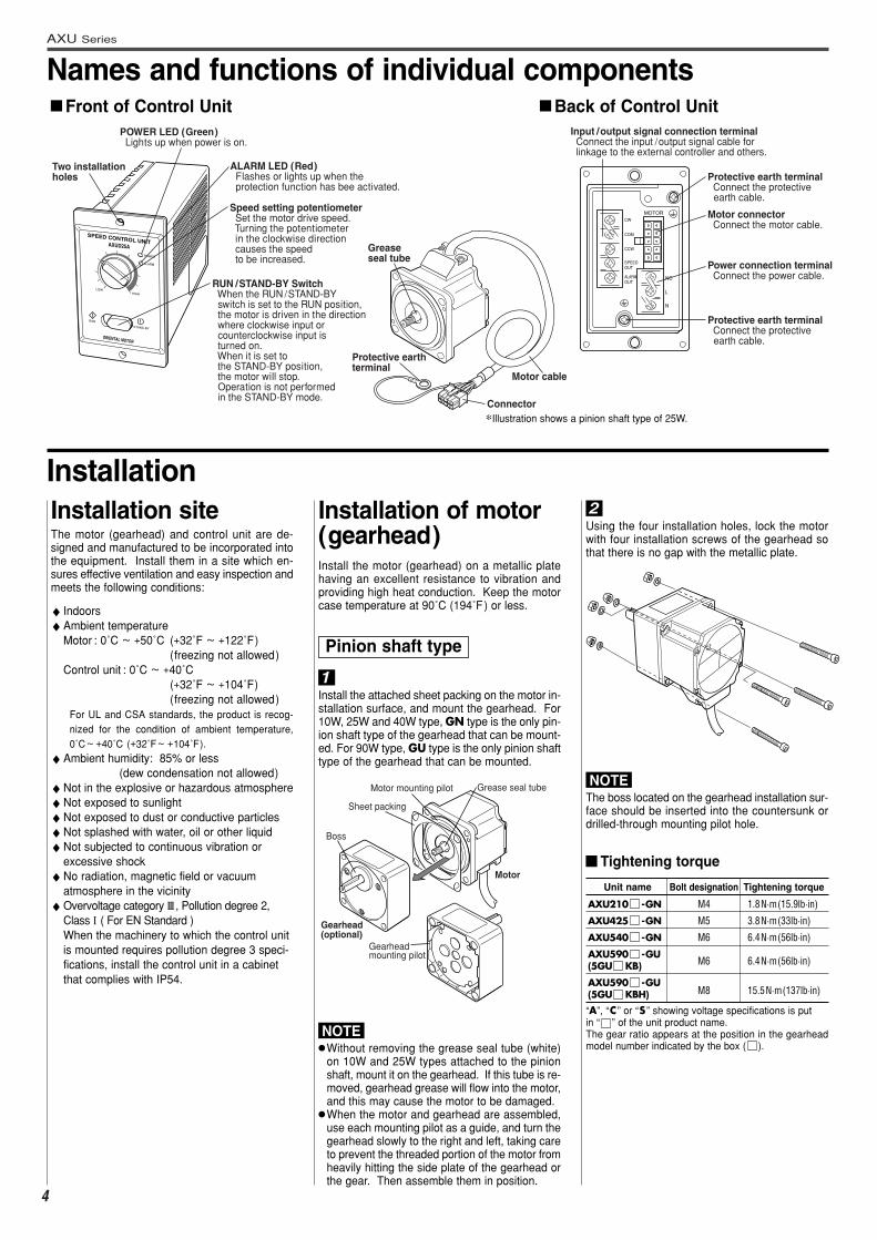
Names and functions of individual components
POWER
ALARM
HIGH
LOW
STAND-BY
RUN
ORIENTAL MOTOR
SPEED CONTROL UNITAXUD25A
Two installation holes
POWER LED (Green) Lights up when power is on.
ALARM LED (Red) Flashes or lights up when the protection function has bee activated.
Speed setting potentiometer Set the motor drive speed. Turning the potentiometer in the clockwise direction causes the speed to be increased.
RUN /STAND-BY Switch When the RUN /STAND-BY switch is set to the RUN position, the motor is driven in the direction where clockwise input or counterclockwise input is turned on. When it is set to the STAND-BY position, the motor will stop. Operation is not performed in the STAND-BY mode.
Front of Control Unit Back of Control Unit
Motor cable
Connector
Protective earth terminal
Grease seal tube
ALARMOUT
SPEEDOUT
CCW
COM
CW
MOTOR
NC
L
N
Input /output signal connection terminal Connect the input /output signal cable for linkage to the external controller and others.
Protective earth terminal Connect the protective earth cable.
Motor connector Connect the motor cable.
Power connection terminal Connect the power cable.
Protective earth terminal Connect the protective earth cable.
∗Illustration shows a pinion shaft type of 25W.
The motor (gearhead) and control unit are de-signed and manufactured to be incorporated intothe equipment. Install them in a site which en-sures effective ventilation and easy inspection andmeets the following conditions:
♦ Indoors♦Ambient temperature
Motor : 0˚C ~ +50˚C (+32˚F ~ +122˚F)(freezing not allowed)
Control unit : 0˚C ~ +40˚C(+32˚F ~ +104˚F) (freezing not allowed)
For UL and CSA standards, the product is recog-nized for the condition of ambient temperature,0˚C~ +40˚C (+32˚F~ +104˚F).
♦Ambient humidity: 85% or less(dew condensation not allowed)
♦Not in the explosive or hazardous atmosphere ♦Not exposed to sunlight♦Not exposed to dust or conductive particles♦Not splashed with water, oil or other liquid♦Not subjected to continuous vibration or
excessive shock♦No radiation, magnetic field or vacuum
atmosphere in the vicinity♦Overvoltage category III , Pollution degree 2,
Class I ( For EN Standard )When the machinery to which the control unitis mounted requires pollution degree 3 speci-fications, install the control unit in a cabinetthat complies with IP54.
Installation
1
Using the four installation holes, lock the motorwith four installation screws of the gearhead sothat there is no gap with the metallic plate.
Installation site
Install the motor (gearhead) on a metallic platehaving an excellent resistance to vibration andproviding high heat conduction. Keep the motorcase temperature at 90˚C (194˚F) or less.
Installation of motor(gearhead)
Without removing the grease seal tube (white)on 10W and 25W types attached to the pinionshaft, mount it on the gearhead. If this tube is re-moved, gearhead grease will flow into the motor,and this may cause the motor to be damaged.
When the motor and gearhead are assembled,use each mounting pilot as a guide, and turn thegearhead slowly to the right and left, taking careto prevent the threaded portion of the motor fromheavily hitting the side plate of the gearhead orthe gear. Then assemble them in position.
The boss located on the gearhead installation sur-face should be inserted into the countersunk ordrilled-through mounting pilot hole.
Install the attached sheet packing on the motor in-stallation surface, and mount the gearhead. For10W, 25W and 40W type, GN type is the only pin-ion shaft type of the gearhead that can be mount-ed. For 90W type, GU type is the only pinion shafttype of the gearhead that can be mounted.
2
Sheet packing
Motor mounting pilot Grease seal tube
Gearhead mounting pilot
Boss
Gearhead (optional)
Motor
Pinion shaft type
NOTE
NOTE
Tightening torque
“A”, “C ” or “S ” showing voltage specifications is put in “ ” of the unit product name.The gear ratio appears at the position in the gearheadmodel number indicated by the box ( ).
Unit name
AXU210 -GN
AXU425 -GN
AXU540 -GN
AXU590 -GU(5GU KB)
AXU590 -GU(5GU KBH)
Tightening torque
1.8N·m(15.9lb·in)
3.8N·m(33lb·in)
6.4N·m(56lb·in)
6.4N·m(56lb·in)
15.5N·m(137lb·in)
Bolt designation
M4
M5
M6
M6
M8
5
AXU Series
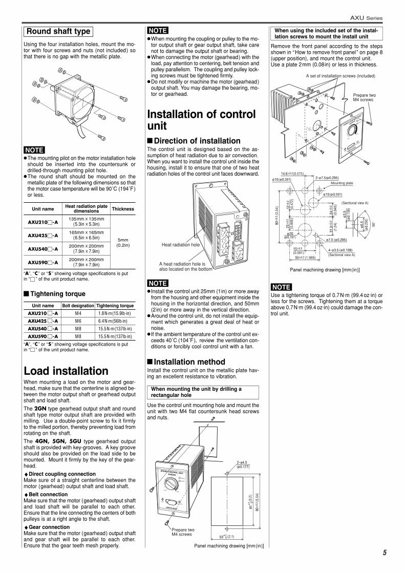
Using the four installation holes, mount the mo-tor with four screws and nuts (not included) sothat there is no gap with the metallic plate.
The mounting pilot on the motor installation holeshould be inserted into the countersunk ordrilled-through mounting pilot hole.
The round shaft should be mounted on themetallic plate of the following dimensions so thatthe motor case temperature will be 90˚C (194˚F)or less.
Unit name
AXU210 -A
AXU425 -A
AXU540 -A
AXU590 -A
Thickness
5mm(0.2in)
Heat radiation plate dimensions
135mm X 135mm(5.3in X 5.3in)
165mm X 165mm(6.5in X 6.5in)
200mm X 200mm(7.9in X 7.9in)
200mm X 200mm(7.9in X 7.9in)
“A”, “C ” or “S ” showing voltage specifications is put in “ ” of the unit product name.
NOTE
Tightening torque
“A”, “C ” or “S ” showing voltage specifications is put in “ ” of the unit product name.
Unit name
AXU210 -A
AXU425 -A
AXU540 -A
AXU590 -A
Tightening torque
1.8N·m(15.9lb·in)
6.4N·m(56lb·in)
15.5N·m(137lb·in)
15.5N·m(137lb·in)
Bolt designation
M4
M6
M8
M8
Load installationWhen mounting a load on the motor and gear-head, make sure that the centerline is aligned be-tween the motor output shaft or gearhead outputshaft and load shaft.
The 2GN type gearhead output shaft and roundshaft type motor output shaft are provided withmilling. Use a double-point screw to fix it firmlyto the milled portion, thereby preventing load fromrotating on the shaft.
The 4GN, 5GN, 5GU type gearhead outputshaft is provided with key-grooves. A key grooveshould also be provided on the load side to bemounted. Mount it firmly by the key of the gear-head.
♦Direct coupling connectionMake sure of a straight centerline between themotor (gearhead) output shaft and load shaft.
♦Belt connectionMake sure that the motor (gearhead) output shaftand load shaft will be parallel to each other.Ensure that the line connecting the centers of bothpulleys is at a right angle to the shaft.
♦Gear connectionMake sure that the motor (gearhead) output shaftand gear shaft will be parallel to each other.Ensure that the gear teeth mesh properly.
When mounting the coupling or pulley to the mo-tor output shaft or gear output shaft, take carenot to damage the output shaft or bearing.
When connecting the motor (gearhead) with theload, pay attention to centering, belt tension andpulley parallelism. The coupling and pulley lock-ing screws must be tightened firmly.
Do not modify or machine the motor (gearhead)output shaft. You may damage the bearing, mo-tor or gearhead.
NOTE
Installation of control unit
Direction of installationThe control unit is designed based on the as-sumption of heat radiation due to air convection.When you want to install the control unit inside thehousing, install it to ensure that one of two heatradiation holes of the control unit faces downward.
Install the control unit 25mm (1in) or more awayfrom the housing and other equipment inside thehousing in the horizontal direction, and 50mm(2in) or more away in the vertical direction.
Around the control unit, do not install the equip-ment which generates a great deal of heat ornoise.
If the ambient temperature of the control unit ex-ceeds 40˚C (104˚F), review the ventilation con-ditions or forcibly cool control unit with a fan.
MOTOR
NC
AC
W
OM
CCW
PEEDUT
ARMUT
Heat radiation hole
A heat radiation hole is also located on the bottom
NOTE
Remove the front panel according to the stepsshown in “How to remove front panel” on page 8(upper position), and mount the control unit.Use a plate 2mm (0.08in) or less in thickness.
STAND-BY
RUNORIENTAL MOTOR
SPEED CONTROL UNIT
AXUD25A
HIGH
LOW
POWER
ALARM
A set of installation screws (included)
Prepare twoM4 screws
2-ø7.5(ø0.295)
4-ø3.5 (ø0.138)
90±0
.2 (3
.54
)
23±0
.2
31.5
±0.2
24±0
.212±0
.2
(0.4
72)
14.6±0.2(0.575)
15±0.2
(0.591)50±0.2 (1.969)
Mounting plate
ø15(ø0.591)
ø15(ø0.591)
ø7.5 (ø0.295)
ø20
ø3.
5
ø6.
5
90°
(Sectional view A)
(Sectional view A)
(0.9
06)
(ø0.787)
(ø0.
138)
(ø0.
256)
(0.9
45)
(1.2
4)
Use a tightening torque of 0.7N·m (99.4 oz·in) orless for the screws. Tightening them at a torqueabove 0.7N·m (99.4 oz·in) could damage the con-trol unit.
NOTE
Panel machining drawing [mm(in)]
Round shaft type When using the included set of the instal-lation screws to mount the install unit
Installation methodInstall the control unit on the metallic plate hav-ing an excellent resistance to vibration.
POWER
ALARM
HIGH
LOW
STAND-BY
RUN
ORIENTAL MOTOR
SPEED CONTROL UNITAXUD25A
Prepare twoM4 screws
2-ø4.5(ø0.177)
81+1
90±0
.2 (3
.54)
53+10
0
(2.1)
(3.2
)
Use the control unit mounting hole and mount theunit with two M4 flat countersunk head screwsand nuts.
When mounting the unit by drilling a rectangular hole
Panel machining drawing [mm(in)]

Applicable standardsEMI
Emission Tests EN61000-6-4Radiated Emission Test EN55011Conducted Emission Test EN55011
EMSImmunity Tests EN61000-6-2Electrostatic Discharge Immunity Test IEC61000-4-2Radiation Field Immunity Test IEC61000-4-3Fast Transient/Burst Immunity Test IEC61000-4-4Surge Immunity Test IEC61000-4-5Conductive Noise Immunity Test IEC61000-4-6Power Frequency MagneticField Immunity Test IEC61000-4-8Voltage Dip Immunity Test IEC61000-4-11Voltage Interruption Immunity Test IEC61000-4-11
Effective measures must be taken against the EMIthat the AXU series may give to adjacent control-system equipment, as well as the EMS of theAXU series itself, in order to prevent a seriousfunctional impediment in the machinery.The use of the following installation and wiringmethods will enable the AXU series to be com-pliant with the EMC directive ( the aforementionedcompliance standards).
6
AXU Series
Installing and wiring in compliance with EMC directive
EMC directive (89/336/EEC,92/31/EEC)
The AXU series has been designed and manu-factured for incorporation in general industrial ma-chinery. The EMC directive requires that theequipment incorporating this product comply withthese directives.The installation and wiring method for the motorand control unit are the basic methods that wouldeffectively allow the customer’s equipment to becompliant with the EMC directive.The compliance of the final machinery with theEMC directive will depend on such factors as con-figuration, wiring, layout and risk involved in thecontrol-system equipment and electrical parts. It,therefore, must be verified through EMC mea-sures by the customer of the machinery.
Install the mains filter as close to the control unitas possible, and use cable clamps and othermeans to secure the input and output cables firm-ly to the surface of the enclosure. Connect the ground terminal of the mains filter tothe grounding point, using as thick and short awire as possible.
Do not place the AC input cable (AWG22: 0.34mm2 or more) parallel with the mains-filter outputcable (AWG22: 0.34 mm2 or more). Parallel place-ment will reduce mains-filter effectiveness if theenclosure’s internal noise is directly coupled to thepower-supply cable by means of stray capaci-tance.
Motor cable connectionTo expand connection between the motor andcontrol unit, use the optional extension cable.Connection can be extended to a maximum of10.5 m (34.4 ft.).
Connecting mains filterInstall a mains filter in the power source line in or-der to prevent the noise generated within the con-trol unit from propagating outside via the AC inputline.For mains filters, use the products as shown in thechart, or an equivalent.
Wiring the signal cableFor the signal cable for the control unit, use ashielded cable of AWG28 (0.09 mm2) or more indiameter, and keep it as short as possible.To ground a shielded cable, use a metal cableclamp or similar device that will maintain contactwith the entire circumference of the shielded ca-ble. Attach a cable clamp as close to the end ofthe cable as possible, and connect it to an ap-propriate grounding point as shown in the figure.
Notes about installation and wiringConnect the motor/control unit and other pe-ripheral control equipment directly to the ground-ing point so as to prevent a potential differencefrom developing between grounds.When relays or electromagnetic switches areused together with the system, use mains filtersand CR circuits to suppress surges generatedby them.Keep cables as short as possible without coilingand bundling extra lengths.Place the power cables such as the motor andpower-supply cables as far apart [100 to 200mm (4 to 8 in.) ] as possible from the signal ca-bles. If they must cross, do so at a right angle.Place the AC input cable and output cable of amains filter separately from each other.
General
Installing and wiring
TDK Corporation
EPCOS
Schaffner Electronik AG
Tyco Electronics CORCOM
Three-phase 200-230V
-
-
FN251-8/07
-
Single-phase 100-115VSingle-phase 200-230V
ZAG2210-11S
B84112-B-B110
FN2330Y-10-06FN2310X-10-06
10ESK1
Shielded cable
Cable clamp
This product has received EMC measures underthe conditions specified in “Example of motor andcontrol unit installation and wiring”. Be sure toconduct EMC measures with the product assem-bled in your equipment by referring to this“Installing and wiring in compliance with EMC di-rective”.
Manufacturer
Grounding procedureThe cable used to ground the control unit, motorand mains filter must be as thick and short to thegrounding point as possible so that no potentialdifference is generated. Choose a large, thick anduniformly conductive surface for the groundingpoint.
How to ground the control unitGround the protective earth terminal at the rear ofthe control unit.Refer to the “Power connection” (page 7) for theway to ground the driver.
How to ground the motorGround the motor by using the protective earthterminal of the motor cable.Refer to the “Motor connection” (page 7) for theway to ground the driver.
Static electricity may cause the control unit to mal-function or become damaged. Do not come closeto or touch the control unit while the power is on
except when operating the speed setting poten-tiometer or switch of the front of control unit.
Precautions about static electricity
Example of motor and control unit installation and wiring
Motor
Control unit
FG
Cable clamp
Signal cable [2 m (6.6 ft.)]Mains filter
PE
Cable clamp
Grounded panel
Power cable
Motor cable [10.5 m (34.4 ft.)]
PE
PE
PE
PE
(Shielded cable)

7
AXU Series
Connect the power cable to the control unit.Connect the red lead wire and black lead wire tothe power connection terminal, and the green/yel-low lead wire to the protective earth terminal.For the power cable, use the attached power ca-ble or a cable with a diameter equivalent to AWG22 (0.34mm2) or more.For the protective earth cable, use a cable with adiameter equivalent to AWG 18 (0.75mm2) or more.For connection, use the insulated round crimp terminal.
1= speed output frequency
T
Speed output frequency(Hz)Motor speed(r/min) = x 60
30
Connection
When you want to extend the input /outputsignal cable, the length must not exceed 2m(6.6ft). The cable should be as short aspossible in order to minimize noise.
The input/output signal cable should be con-nected to run perpendicular to the power ca-ble and motor cable, not in parallel with thepower cable and motor cable.
Speed outputConcurrently with motor drive, the system outputspulse signals (with a width of about 0.5 ms) at30 pulses per rotation of the motor output shaft.You can measure the speed output frequency andcalculate motor speed.
The direction of rotation is the direction where themotor output shaft is driven when viewed from themotor output shaft side.The direction of gear output shaft rotation may bethe reverse of the motor drive direction, depend-ing on the speed reduction ratio of the gearhead.
Input /output signals
MOTORCW
COM
CCW
SPEEDOUT
ALARMOUT
NC
L
N
CW input
CCW inputCOM
SPEED outputALARM output
Input circuit( Internal circuit )
Output circuit( Internal circuit )
ALARM outputIn the following cases, the protection function ofthe control unit is enabled to turn off the ALARMoutput (level H) and to stop the motor.In this case, the LED flashes or lights up to allowthe protection function to be checked.∗ It is normal that the LED lamp will turn on in a
moment of the connection with power supply.
LED lamp flashes when the following pro-tection function
Overload protection functionThe LED lamp flashes when a load in excess ofthe rated torque is applied to the motor for about5 seconds or more, or when the motor is instant-ly stopped or when the direction of rotation isswitched repeatedly in a short period of time.
LED lamp ON when the following protec-tion function
Open-phase protection functionPrevents motor malfunction when the sensor ca-ble within the motor cable is disconnected duringmotor operation. (An alarm signal will not be out-put while the motor is at a standstill.)
Overvoltage protection functionWhen the motor is used in an elevating/ loweringapplication or with a load in excess of the per-missible load inertia, or when voltage applied tothe control unit has exceeded the voltage setting(115VAC or 230VAC) by 20% or greater.
Insufficient voltage protection functionWhen voltage applied to the control unit is lessthan the voltage setting (100VAC or 200VAC) by30% or greater.
Overspeed protection functionWhen motor speed has reached an excess of2800 r/min.
When an electrical connection is made as shownin the example, the ALARM output is turned on(level L) if the control unit is normal but is turnedoff (level H) in the event of alarm.When the ALARM output is turned off (level H),turn off the power to the control unit once the mo-tor stops.If the motor cable is free of any trouble, check theoperating conditions (load torque, running patternand power supply voltage).After removing the cause for activating the pro-tection function, turn on power again and reset thealarm.Once power has been turned off, wait at least 30seconds before turning it on again.
If you want to indicate or monitor the motor outputshaft speed and determine the speed of the gear-head output shaft, use an optional digital speedindicator SDM496.
Signal output is open collector output.Use the power source of 26.4 VDC or less to con-nect the limit resistance (R) so that output currentdoes not exceed 10mA.
CWCCW
COM
SPEEDALARM
COM
+14V
2kΩ
Reinforced photocoupler insulation
Reinforced photocoupler insulation
NC
L
N
Single-phase100-115V ±10% 50/60Hz
To power supply
Single-phase 100 to 115V
Three-phase200-230V ±10% 50/60Hz
L1
L2
L3
Three-phase 200 to 230V
To power supply T
0.5ms
ø3.2mm (ø0.126in) or more
9mm (0.354in) or more
6.2m
m(0
.244
in)
or le
ss
< Applicable crimpterminal >
SPEED OUTALARM OUT
COM
Control UnitControllerVcc
R
W
OM
CCW
PEED
ARM
MOTOR
Motor connecting connector
Motor cable
Grounding
Terminal cover
To power supply
Power connection terminal
Terminal cover
Input /output signal connection terminal For connection, use a twisted pair or shielded wire AC
Cable included with the product
MotorControl unit
NOTE
NOTE
After shutting down the power, wait at least 30seconds before turning it back on, unplugging, orplugging in the motor’s cable connector.
NOTE
Motor connectionInsert the motor cable connector into the motorconnector of the control unit.Insert it until a click sound is audible, and connectit firmly.To expand connection between the motor andcontroller, use the optional extension cable.Connection can be extended to a maximumof 10.5m (34.4ft ).When an extension cable is used or direct con-tact between the hands and motor is anticipat-ed, connect the protective earth lead wire(green/yellow, with a round terminal) of the mo-tor cable directly to the ground.If the protective earth lead wire is not sufficientlylong, use a lead wire with a diameter equivalentto AWG 18 (0.75mm2) or more to extend theprotective earth lead wire and then connect it tothe ground over the shortest possible distance.An extension lead wire must be provided sepa-rately by the customer.Additionally, the dedicated extension cable (soldseparately) is not provided with a protectiveearth lead wire. Be sure to provide grounding ata relay point or extend the cable for grounding.
Power connection
Single-phase200-230V ±10% 50/60Hz
NC
L
N
Single-phase 200 to 230V
To power supply

8
AXU Series
Do not use a solid state relay (SSR) to turn onor off power. The motor control unit may be damaged if it isused.
When you want to use the controller with a built-in clamp diode, pay attention to the sequenceof turning on or off the power.
Power ON : Controller ON →Control unit ON
Power OFF : Control unit OFF →Controller OFF
Precautions for useIf the control unit power is turned on first whenconnected as shown on the right, or the controllerpower is turned off with the control unit powerturned on, current will be applied, as indicated byarrow mark of the diagram, and this may causethe motor to be driven. When the power is turnedon or off simultaneously, the motor may be driventemporarily due to differences in power capacity.The controller power must be turned on first, andcontrol unit power must be turned off first.
CWCCW
COM
+14VVcc
Control UnitController
AXUD25ASPEED CONTROL UNIT
ORIENTAL MOTOR
POWER
ALARM
HIGHLOW
STAND-BYRUN
RUN/STAND-BY switch
Speed setting potentiometerTurning the potentiometer in the clockwise direction causes the speed to be increased.The speed can be set in the range from100 to 2000 r/min. It is set to 0 r/min at the time of shipment.
Running
Running by theRUN/STAND-BY switch ofthe control unit(Use the short circuit bar.)
The RUN/STAND-BY switch is not a powerON/OFF switch.When you want to stop the motor for a longtime, turn off the control unit power.
Wait at least 1 second after the power isturned ON, then operate the motor. The mo-tor will not run if RUN input or CW (CCW) in-put is turned ON within 1 second.
CW
COM
CCW
OFFON
OFFON
CW
COM
CCW
Connect the attached short circuit piece betweenthe CW and COM or CCW and COM.Do not use the short circuit bar for other purpos-es.
Running by external signals
Small-capacity switch and relay
Transistor output type controller
Use a small-capacity contact type relay capa-ble of opening and closing 12 VDC, 5mA.
When the RUN/STAND-BY switch is set to theRUN position, and the motor is driven. When it is set to the STAND-BY position, the mo-tor will stop. Operation is not performed in theSTAND-BY mode.
STAND-BYRUN
STAND-BYRUN
Set the RUN/STAND-BY switch to the RUNposition.
Clockwise driveWhen CW input is turned on (level L), themotor is driven in the clockwise direction.When CW input is turned off (level H), themotor is stopped.
Counterclockwise driveWhen CCW input is turned on (level L), themotor is driven in the counterclockwise di-rection.When CCW input is turned off (level H), themotor is stopped.
♦When both the CW and CCW inputs areturned on (level L), the motor is stopped in-stantly.The motor cannot be reversed instanta-neously.
CWCCW
Drive direction depends on how the short circuitbar is connected.
NOTE
CCW
COM
CW
CCW
COM
CW
Short circuit bar
Short circuit bar
Clockwise direction Counterclockwise direction
Run/direction of rotation selection
Run/reversing after instantaneous stop
RUN/STAND-BY switch
CW input
CCW input
Motor operation
STAND-BY
RUN
ON
OFF
OFF
ON
CW
CCW0.5s∗
20ms min.
20ms min.
When both the CW and CCW inputs are turned on, the motor is stopped instantaneously.
∗Motor does not run for 0.5s after instantaneous stop, if a reversing run signal is input.
Running by external signal
The CW and CCW input signals must be ON forat least 20ms.
NOTE
Timing chart

AXU Series
The motor and control unit may not operate correctly during motor operation due to speed setting erroror electrical connection error. If the motor cannot be driven correctly, take the appropriate measuresaccording to the following Table. If correct motor operation cannot be regained despite such measures,contact our sales office.
Trouble diagnosis and countermeasures
Trouble Possible cause MeasurersThe motor fails to rotate. The RUN/STAND-BY switch is set to the STAND-
BY position.
Both CW and CCW inputs are turned on.
The speed setting potentiometer is not adjusted.
The protection function has been activated.(ALARM LED lamp flashes or lights up.)
Set the RUN/STAND-BY switch to the RUN position. Turn oneither CW or CCW input.
Turn off either CW or CCW input.
Turn the speed setting potentiometer slightly in the clockwisedirection.
Check for the cause of the protection function activation andtake the appropriate measures.
The motor turns in the directionopposite to the specified one.
The CW input and CCW input are incorrect orelectrical connection is wrong.
The motor rotates in the opposite direction, de-pending on gearhead speed reduction ratio.
Supply correct input signals.When CW input is at level L, the motor shaft rotates in the CWdirection. When CCW input is at level L, it rotates in the CCWdirection.
Reverse the CW and CCW input operations.[Rotating opposite of motor direction]GN type :
1/25, 1/30, 1/36GU type :
1/12.5, 1/15, 1/18, 1/75, 1/90, 1/100, 1/120, 1/150, 1/180
Motor operation is not stable.There is much vibration.
The centerline is not aligned between the motor(gearhead) output shaft and load shaft.
The motor and gearhead are not assembled cor-rectly.
Check the connection between the motor (gearhead) outputshaft and load shaft.
Check how the motor and gear head are assembled. Alsocheck pinion shaft type.
Remove the control knob of thespeed setting potentiometer.Put a screwdriver ( ) or the like betweenthe front panel and the control knob.Then, pull the control knob toward you,and it will be removed. (Keep the knobcompletely at the LOW position.)
STAND-BY
RUNORIENTAL MOTOR
SPEED CONTROL UNIT
AXUD25A
HIGH
LOW
POWER
ALARM
Slow start /slowdown time setting potentiometer
Front panel
The motor starts slowly when it starts up, and stopsslowly when it stops. This slow start and slowdowntime can be set within the range from 0.5 to 10 sec.(2000 r/min without load).
Remove front panelHold only the front panel, and pull ittoward you. Then the front panel canbe removed.In this case, the RUN / STAND-BYswitch is also removed together.Care should be taken not to lose it.Reverse the above steps if you wantto install the front panel.
How to remove front panel
Setting the slow start /slowdown time
Slow start /slowdown timesetting potentiometerTime is increased by turning theswitch in the clockwise direction.Use a insulated Phillips screw-driver for this operation.The shortest time is selected atthe time of shipment.
LongShort
STAND-BY
RUNORIENTAL MOTOR
SPEED CONTROL UNIT
AXUD25A
HIGH
LOW
POWER
ALARM
9
Conduct the insulation resistance measurement or withstand voltage testseparately on the motor and the driver.Measuring insulation resistance or conducting dielectric-strength test withthe motor and driver connected may damage your product.
NOTE

Unauthorized reproduction or copying of all or part of this manual is prohibited.If a new copy is required to replace an original manual that has been damaged or lost, please contact your nearest Oriental Motorbranch or sales office.
Oriental Motor shall not be liable whatsoever for any problems relating to industrial property rights arising from use of any informa-tion, circuit, equipment or device provided or referenced in this manual.
Characteristics, specifications and dimensions are subject to change without notice. While we make every effort to offer accurate information in the manual, we welcome your input. Should you find unclear descriptions,
errors or omissions, please contact the nearest office. is a registered trademark or trademark of Oriental Motor Co., Ltd., in Japan and other countries.
Other product names and company names mentioned in this manual may be registered trademarks or trademarks of their respectivecompanies and are hereby acknowledged. The third-party products mentioned in this manual are recommended products, and refer-ences to their names shall not be construed as any form of performance guarantee. Oriental Motor is not liable whatsoever for theperformance of these third-party products.
© Copyright ORIENTAL MOTOR CO., LTD. 2008