Embed Size (px)
Citation preview

www.ueonline.com/st
Background, Concepts and Terms

AGENDA
• Why do we need a Safety Instrumented System (SIS)? • Defining SIS• Determining the Safety Integrity Level (SIL)• The language (and many acronyms) of Safety Instrumented Systems
• Improving the SIS function• Issues driving the industry
www.ueonline.com/st

THE PROCESS INDUSTRY CHALLENGEBalancing Safety and Throughput
Society:Employees’ SafetyThe Community’s
SafetyThe Environment
The Process Owner: Make a profitMaintain assetsGood corporate
image
www.ueonline.com/st

PAGE
5
http://youtu.be/ISNGimMXL7M(the 2:50 mark)
Because humans can make bad decisions under pressure
WHY ARE SAFETY INSTRUMENTED SYSTEMS IMPORTANT?
www.ueonline.com/st

PROCESS CONTROL VS. SAFETY
• BPCS – continuously operates the process plant during normal startup, running and shutdown phases (engine control)
• SIS – brings the plant to a safe state from a hazardous state upon demand (antilock brakes)
When properly designed per IEC 61511, these systems are always separate, independent and autonomous.
Good process control isn’t enough!
www.ueonline.com/st

BPCS AND SIS RELATIONSHIPSeparate but equally important!
www.ueonline.com/st

THE PURPOSE OF A SAFETY SYSTEM
…to bring a process to a safe state (ESD) or permit the process to continue in a safe manner when all specified conditions are satisfiedExamples:
‐ Emergency Shutdown System (ESD)‐ Safety Interlock- Safety Shutdown‐ Starting Permissive
www.ueonline.com/st

PROCESS SAFETY SYSTEM STANDARDS
• IEC 61508: – Internationally‐recognized standard for safety‐related system design of hardware and software
– Applies to manufacturers of safety system components (e.g., the One Series Safety Transmitter)
– IEC 61511:– applies to the process industries that use these components to design a Safety Instrumented System (i.e., UE’s customers)
– Defines the methods a user needs to develop a safety system
IEC 61508 and IEC 61511
www.ueonline.com/st
SIF VS. SIS
SIS: A Safety Instrumented System …an instrumented system used to implement one or more safety instrumented functions (SIFs). An SIS is composed of any combination of sensors, logic solvers and final elements (e.g., the entire safety system of the reactor, including temperature, pressure, level, etc.)
SIF: A Safety Instrumented Function … the method by which the risk of a specific hazard is reduced automatically, using sensors, logic solvers and final elements (e.g., high pressure interlock on a reactor)
www.ueonline.com/st

SIMPLE SIS EXAMPLE
www.ueonline.com/st

DETERMINING THE NEED FOR A SIS
• The user must conduct a Hazards and Operability study (Hazop) to determine the types of failure or malfunction that could occur in the process.
• This hazard analysis will lead to the decision of whether a SIS is required.
• If it is, the user must then decide what Safety Integrity Level (SIL) is required for the process. The user can use a variety of techniques for this, including Levels of Protection Analysis (LOPA).
• Let’s look a bit closer at this.
www.ueonline.com/st

LOPA
• A LOPA uses the idea of Defense in Depth, offering many interlocking opportunities to prevent a problem from spreading
• Note: the safer the basic process, the less you need the other layers . . .
Layers of Protection Analysis
Respond: Plant and Community actions
Mitigate: the SIS, passive layers like walls
Prevent: the SIS , mechanical devices, and operator actions
Automatic Control: The BPCS
The Design of the Process
www.ueonline.com/st
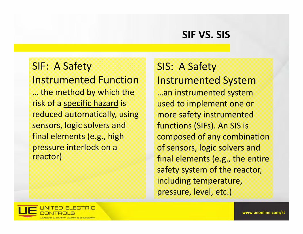
A LOPA ANALOGY
Layers of Protection A Process A Car
Basic Design Proper specifications for the process
Proper specs for the usage (e.g., 4x4 or mini‐van)
Process Control BPCS (DCS, PLC’s, etc.) Gas pedal, transmission,engine
Prevention Alarms, interlocks, SIS functions
Steering, brakes, anti‐skidand anti‐lock brakes
Mitigation SIS functions, walls, dikes, fire suppression
Bumpers, airbags, crumple zones
Response Evacuation, fire and emergency response, communication
Onstar, cell phone, police, fire, ambulance
www.ueonline.com/st

SIL
• SIL is a measure of the performance and reliability of a SIF when it is called upon to do its job (i.e., protect).
• It can only be specified for a loop, not an individual device. There are no “SIL 2‐Rated” devices!
• You cannot say a system is “safe” or “unsafe” – you must define the amount of risk within the process that is tolerable
Safety Integrity Level
www.ueonline.com/st
SIL
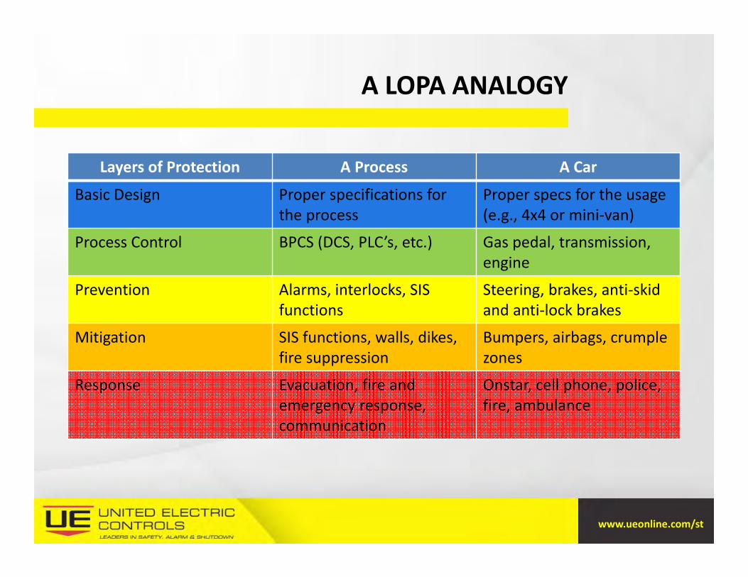
• There are four SIL categories, based on a 10X reduction of risk at each level (but there are virtually no SIL 4 applications in the process industry)
www.ueonline.com/st

SIL
• Basically, SIL is defined by:– the likelihood of a failure within the safety system:
• Probability of Failure on Demand (PFD) and its reciprocal, the Risk Reduction Factor (RRF)
– the impact of such a failure on the system • Hardware Fault Tolerance (HFT) and • Safe Failure Fraction (SFF)
– the consequences of that failure
• Let’s look at each of these
www.ueonline.com/st

PFD AND RRF
• In a system that is passive under normal operating conditions, the PFDavg tells an engineer the average probability that a device won’t work when called upon. This is expressed as a decimal (e.g., x10‐3)
• The RRF is the reciprocal of the PFD. For instance, if the RRF is noted as 806, then the PDFavg would be 1/806 (0.00124), putting it into the SIL2 level.
Probability of Failure on Demand, and Risk Reduction Factor
SIL Description RRF PFDavg
1 Minor property and production Impact >10 to ≤ 100 0.1‐0.01
2 Major property & production impact; possible injury >100 to ≤ 1,000 0.01‐0.001
3 Employees and community impact >1,000 to ≤ 10,000 0.001‐0.0001
4 Catastrophic community impact >10,000 to ≤ 100,000 0.0001‐0.00001
www.ueonline.com/st

HFTHardware Fault Tolerance
• HFT is a measure of redundancy built into an instrument or system – HFT=0 The device or system loses its ability to protect if any single component fails
– HFT=1 A device can still function properly if any one component fails (dual redundancy)
– HFT=2 A device can still function if two separate components fail (triple redundancy)
www.ueonline.com/st

SFF
• Device failures can be broken down into four blocks:
Safe Failure Fraction
Safe & DetectedA nuisance, but doesn’t affect the proper operation of the system (e.g., a normally‐visible LCD display segment is damaged)
Safe &UndetectedA nuisance, but doesn’t affect the proper operation of the system (e.g., a normally‐blank LCD display segment, visible only when a menu is triggered, is damaged)
Dangerous & DetectedSerious but allows for proactive response (e.g., an electrical surge causes the output to fail and the system recognizes this)
Dangerous and UndetectedVery serious – the safety function will not occur if required, and is unknown (e.g., a pressure spike damages the sensor, but not completely, and the output drifts erratically. The system may not be able to detect this)
www.ueonline.com/st

SSF
• The SFF of a device is determined by:– Analyzing all of the possible failure modes in that product– Determining how each of those failures falls into the four categories
Defining the SFF
– Adding up all but the Dangerous/Undetected faults
– Dividing that by the total number of possible faults.
• This gives you a percentage of diagnostic coverage
www.ueonline.com/st
PUTTING SFF AND HFT TOGETHER
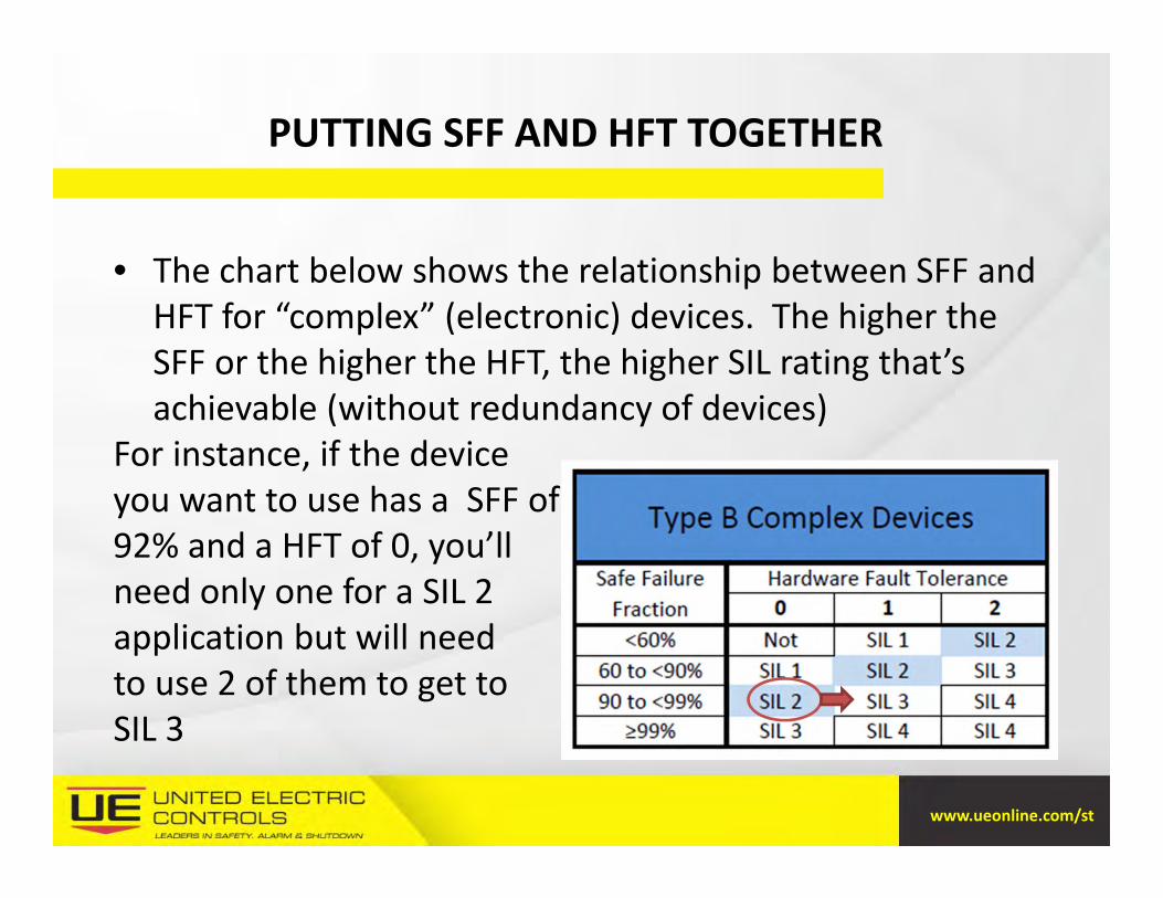
• The chart below shows the relationship between SFF and HFT for “complex” (electronic) devices. The higher the SFF or the higher the HFT, the higher SIL rating that’s achievable (without redundancy of devices)
For instance, if the deviceyou want to use has a SFF of 92% and a HFT of 0, you’ll need only one for a SIL 2 application but will need to use 2 of them to get toSIL 3
www.ueonline.com/st

THE SOURCES OF SIS FAILURES
Because they are in the environment and usually connected to the process, Sensors and Final Elements are more susceptible to failure than Logic SolversSo if we assume all devices fail (and they do), then devices with the most diagnostic coverage (highest SFF) will give us the most peace of mind
What Could Possibly Go Wrong?
www.ueonline.com/st

IMPROVING THE SAFETY SYSTEM
• In addition to improving the reliability of the devices themselves, there are a number of ways that designers can improve the overall reliability of their systems:– Diversity– Redundancy– Voting Logic – Proof Testing Intervals
www.ueonline.com/st

DIVERSITY
• Use diverse technologies to increase overall system reliability • Use diverse technologies to avoid common mode failures
www.ueonline.com/st
REDUNDANCY
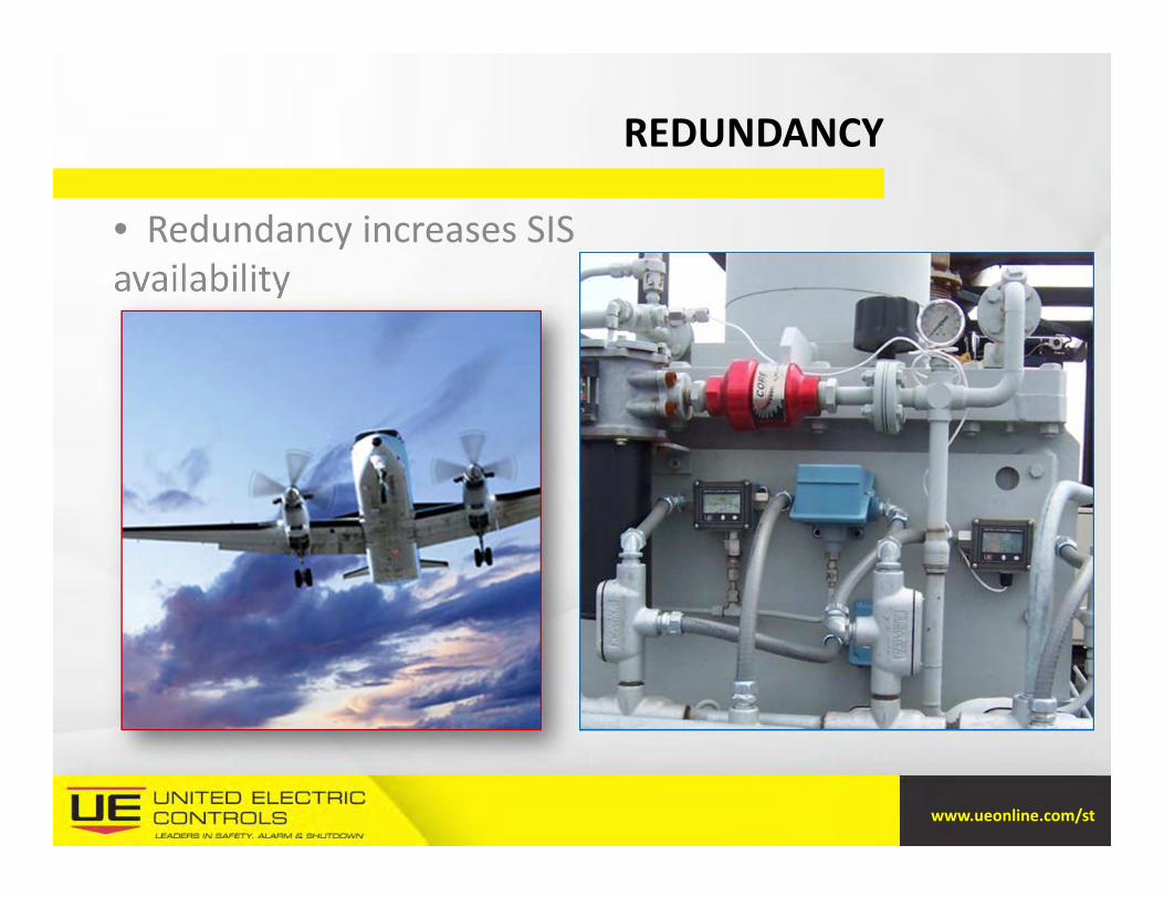
• Redundancy increases SIS availability
www.ueonline.com/st

VOTING LOGIC
1oo1 – 1 out of 1 or “Simplex” system - a single channel with zero fault tolerance
1oo2 – dual channel 1 out of 2, either channel causes an ESD, increases system integrity but causes more spurious (nuisance) trips
www.ueonline.com/st

VOTING LOGIC
• 2oo3 – Triple Modular Redundancy (TMR)– 2 out of 3, two channels must agree for ESD– If one channel fails, defaults to 1oo2
– Does not cause a spurious trip, safety is not compromised, two channels continue to operate.
– Any drawbacks or trade‐offs here?
www.ueonline.com/st

PROOF TESTING
• An SIS system must be tested periodically to prove the essential components will work when needed
• More frequent testing means greater assurance the components are in good working order
– Results in a lower Probability to Fail on Demand (PFDavg)– and higher Risk Reduction Factor (RRF)
Will your equipment work when needed?
www.ueonline.com/st

PROOF TESTING
Option IssuesDesign the SIS so that it doesn't need testing during the long periods between plant shutdowns.
Cost of components and materials that are able to achieve that?
Install bypass lines around each final control element to facilitate full proof testing while the process remains in operation
No protection during testing!Bypass lines may be inadvertently left open (so no protection ever)!
Use manual or automated partial‐stroke valve testing to reduce the PFDavg.
May not prove that valve will close completely under demand
Want to make it easier?
www.ueonline.com/st

KEY INDUSTRY DRIVERS
The need for improved levels of safety Lack of end user SIS & SIL understanding Increasing adoption of SIL certified instrumentation $10b of old legacy safety systems needing replacement High cost and downtime has decreased safety by delaying
system upgrades Both switches and transmitters are currently used, so
retrofitting is more complicated Old systems prone to failure
What’s Keeping YOU up at night?
www.ueonline.com/st

CONCLUSIONS
• The Process Owner faces an important question: How can I keep my process running as much as possible (to maximize profit), but prevent any accidents (to maximize safety)?
• A properly designed Safety Instrumented System plays an important role in answering that question, providing the proper balance between uptime and safety.
www.ueonline.com/st

Thank you for your interest!
Questions?
www.ueonline.com/st

![rrf; Rm, ~ ~ - Jm.cft'll~~~ JIQr\'9 ~ 'rrf;'Jf!I'< Rm, ~ ~ - 110002 1hnak Bha"sn, 9BahadurShab Zaf01'M.,.:, NowO.lhl-110001~'Phon.: +91-11-H23085M3230lOHll132]01'375"23119401.*-m](https://img.pdfslide.tips/doc/110x75/60b12311f37180624960d60c/rrf-rm-jmcftll-jiqr9-rrfjfi-rm-110002-1hnak-bhasn.jpg)