Embed Size (px)
Citation preview

Background
of
Component Based Finite Element Method
Lukáš Gödrich, František Wald, Marta Kurejková, Martin Kočka
Czech Technical University in Prague

Introduction
Connection design
Models
Component
method
FE analyse
Validation
and verification
Component based
FEM
Bolted joints
Slender plates
Connection
behaviour
Summary
List of contents
• Connection design
– Models
– FE analyse
• Validation & Verification
• Components modelling
– Bolts
– Slender plates
• Connection behaviour
• Summary
2

Introduction
Connection design
Models
Component
method
FE analyse
Validation
and verification
Component based
FEM
Bolted joints
Slender plates
Connection
behaviour
Summary
Description of behaviour for design
by moment-rotation characteristic
Connection exposed to bending
• Rotational stiffness
• Moment resistance
• Rotation capacity
3
Design curve
Joint resistance
M j, Rd
Deformation capacity
j,Cd
Initial stiffness Sj, ini
Elastic
2/3 M j, Rd
limit
Experimental curve
Rotation, , mrad
M, moment, kNm

Introduction
Connection design
Models
Component
method
FE analyse
Validation
and verification
Component based
FEM
Bolted joints
Slender plates
Connection
behaviour
Summary
Joint design
European standards
• EN1993-1-8, Eurocode 3, Design of steel structures, Part
1-8, Design of joints, CEN, Brussels, 2006.
• EN1994-1-1, Eurocode 4, Design of composite steel and
concrete structures, Part 1-1, General rules and rules for
buildings, CEN, 2010.

Introduction
Connection design
Models
Component
method
FE analyse
Validation
and verification
Component based
FEM
Bolted joints
Slender plates
Connection
behaviour
Summary
Design approaches
for structural joints
Models
• Experimental
• Curve fitting
• Analytical
– Component Method CM
• Finite element analysis
– Research
– Design finite element analysis
• Component based finite element method
CBFEM
5

Introduction
Connection design
Models
Component
method
FE analyse
Validation
and verification
Component based
FEM
Bolted joints
Slender plates
Connection
behaviour
Summary
Curve fitting model
• Based on
– Physical experiments
– In EN1993-1-8 Ch.7 - Hollow section joints
6
M
Experiment
Function h
t
lb
a
t M 5
53
31
1 )kM(C)kM(C)kM(C

Introduction
Connection design
Models
Component
method
FE analyse
Validation
and verification
Component based
FEM
Bolted joints
Slender plates
Connection
behaviour
Summary
Component model
Procedure
Web panel in shear
Connection
Components in tension
Column web in tension
Column web in compression
Components in compression
Joint
Decomposition of joint
Component description
Joint assembly
Classification
Representation
Modelling in analyses

Introduction
Connection design
Models
Component
method
FE analyse
Validation
and verification
Component based
FEM
Bolted joints
Slender plates
Connection
behaviour
Summary
Component Model
Application
Design tables
Green book
Blue book
Computer programs
Simplified hand calculation
8

Introduction
Connection design
Models
Component
method
FE analyse
Validation
and verification
Component based
FEM
Bolted joints
Slender plates
Connection
behaviour
Summary
Component Model
Design tools
• Inputs
• Outputs
• Reports
• For limited
cases
9
www.fine.cz
Introduction
Connection design
Models
Component
method
FE analyse
Validation
and verification
Component based
FEM
Bolted joints
Slender plates
Connection
behaviour
Summary
Finite Element models of joint
• Research oriented
• Design oriented
10Research model Design model

Introduction
Connection design
Models
Component
method
FE analyse
Validation
and verification
Component based
FEM
Bolted joints
Slender plates
Connection
behaviour
Summary
Research oriented FEA
Current models of bolts
• Solid elements
• Complex models including
– Tread
– Tightening
• Material
– damage model
11Wu, Z., Zhang, S. and Jiang, S.: Simulation of tensile bolts in finite element modeling of semi-rigid beam-
to-column connections, International Journal of Steel Structures, 2012,12/3, 339-350.
Introduction
Connection design
Models
Component
method
FE analyse
Validation
and verification
Component based
FEM
Bolted joints
Slender plates
Connection
behaviour
Summary
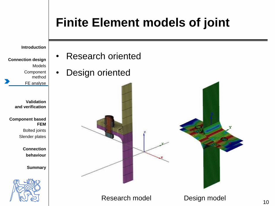
Bearing
FEM modelling
• von-Mises yield criterion
• Demage models
12
Može P., Beg D., A complete study of bearing stress in single bolt
connections, Journal of Constructional Steel Research, 95, 2014, 126–140.

Introduction
Connection design
Models
Component
method
FE analyse
Validation
and verification
Component based
FEM
Bolted joints
Slender plates
Connection
behaviour
Summary
Connections
FE research models
13
• Bursi and Jaspart (1998)
– T-stub and Extended end-plate moment
– LAGAMINE, a finite element research software– Bursi O. S., Jaspart J. P., Benchmarks for Finite Element Modelling of Bolted Steel
Connections, Journal of Constructional Steel Research, 43 (1-3), 1997, 17-42.
– Used for further validation in COST C1 action• Virdi K. S. et al, Numerical Simulation of Semi Rigid Connections by the Finite
Element Method, Report of Working Group 6 Numerical, Simulation COST C1,
Brussels Luxembourg, 1999.
Introduction
Connection design
Models
Component
method
FE analyse
Validation
and verification
Component based
FEM
Bolted joints
Slender plates
Connection
behaviour
Summary
Validation and verification
procedures
• Well developed in FEM theory
• To check the physical accuracy
• To check the proper use
• To check the asked design level
14

Introduction
Connection design
Models
Component
method
FE analyse
Validation
and verification
Component based
FEM
Bolted joints
Slender plates
Connection
behaviour
Summary
Definitions
of Verification & Validation
15
Validationcompares the numerical solution with the experimental data.
Validation can be practically split into three tasks:
• to detect and separate the model’s significant discrepancies,
• to remove and reduce removable and unavoidable errors,
• to evaluate uncertainties in the results.
Verificationuses comparison of computational solutions with highly accurate (analytical
or numerical)
Verification is supposed to deliver evidence that mathematical models are
properly implemented and that the numerical solution is correct with respect
to the mathematical model.

Introduction
Connection design
Models
Component
method
FE analyse
Validation
and verification
Component based
FEM
Bolted joints
Slender plates
Connection
behaviour
Summary
Definitions
of Verification & Validation
16
ISO/FDIS 16730
Fire safety engineering - Assessment, verification and validation of
calculation methods, Geneva, 2008.
Introduction
Connection design
Models
Component
method
FE analyse
Validation
and verification
Component based
FEM
Bolted joints
Slender plates
Connection
behaviour
Summary
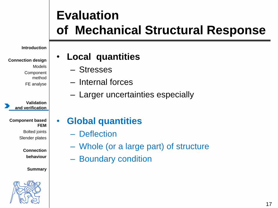
Evaluation
of Mechanical Structural Response
• Local quantities
– Stresses
– Internal forces
– Larger uncertainties especially
• Global quantities
– Deflection
– Whole (or a large part) of structure
– Boundary condition
17

Introduction
Connection design
Models
Component
method
FE analyse
Validation
and verification
Component based
FEM
Bolted joints
Slender plates
Connection
behaviour
Summary
Component based FEMSystem response quantity
• Joint analyses by FEM
– Design material model
• Component behaviour
– Connectors
• Bolts
– In tension
– In shear
• Welds
• Anchor bolts
– Slender plates
– Concrete block18

Introduction
Connection design
Models
Component
method
FE analyse
Validation
and verification
Component based
FEM
Bolted joints
Slender plates
Connection
behaviour
Summary
Material for FE design model
• Bilinear ideal elastic-plastic model
19Može P., Beg D., A complete study of bearing stress in single bolt connections, JCSR, 95 (2014) 126–140
True stress-strain
Experimental
Design
5%

Introduction
Connection design
Models
Component
method
FE analyse
Validation
and verification
Component based
FEM
Bolted joints
Slender plates
Connection
behaviour
Summary
20
3D – bricks 2D elements - shells
Plate modelling
o Shells for design
o 8 degree of freedom elements
o 4 notes (degrades to 3)
o Allowing plastification, membrane effects, bifurcation

Introduction
Connection design
Models
Component
method
FE analyse
Validation
and verification
Component based
FEM
Bolted joints
Slender plates
Connection
behaviour
Summary
Design model of bolt
o Bars and springs
o In tension – stiffness, resistence, deformation capacity
o In shear – stiffness, resistence, deformation capacity
21
Introduction
Connection design
Models
Component
method
FE analyse
Validation
and verification
Component based
FEM
Bolted joints
Slender plates
Connection
behaviour
Summary
22
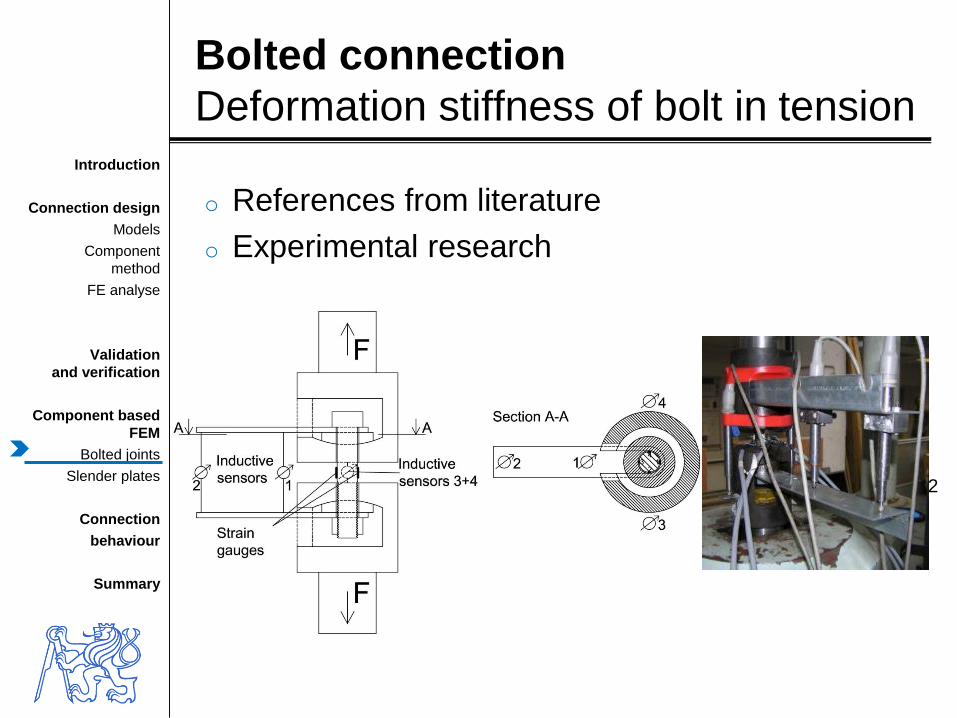
Bolted connection
Deformation stiffness of bolt in tension
o References from literature
o Experimental research

Introduction
Connection design
Models
Component
method
FE analyse
Validation
and verification
Component based
FEM
Bolted joints
Slender plates
Connection
behaviour
Summary
23
No. Diameter Material
Bolt
length
ls
Grip
length
lt
Nut
height
ln
Washer
height
lw
Head
height
Lh
[mm] [mm] [mm] [mm] [mm]
1 M20 8.8 81.5 42.2 15 0 12.6
2 M16 10.9 109 35.4 17 2 x4 10.1
3 M16 10.9 108.2 4 17 2x4.1 10.2
4 M16 10.9 108.2 10.5 12.7 2x4.1 10.2
5 M20 8.8 57.7 32.9 15.1 0 12.6
6 M20 8.8 0 99.3 15.6 3.1+3.2 12.6
7 M20 8.8 57.3 34.4 15.5 0 12.5
8 M20 8.8 57.7 32.1 15.2 2x3 12.5
9 M20 8.8 57.7 31.7 15.3 0 12.5
10 M20 8.8 83.4 19.4 30.4 2x2.9 12.7
11 M20 8.8 0 83.5 31 0 12.5
12 M16 10.9 107.7 18.6 17.1 0 10.2
13 M16 10.9 108.1 25.4 12.7 2x4.1 10
List of own experiments
o Two failure modes
o Rupture of thread
o Tearing down of nut

Introduction
Connection design
Models
Component
method
FE analyse
Validation
and verification
Component based
FEM
Bolted joints
Slender plates
Connection
behaviour
Summary
Behaviour based on bolt failure
24
24

Introduction
Connection design
Models
Component
method
FE analyse
Validation
and verification
Component based
FEM
Bolted joints
Slender plates
Connection
behaviour
Summary
Validation for rupture of thread
25
Deformation, mm
Fo
rce,
kN
Experiment
Research FEM

Introduction
Connection design
Models
Component
method
FE analyse
Validation
and verification
Component based
FEM
Bolted joints
Slender plates
Connection
behaviour
Summary
Validation for tearing down of nut
26
Deformation, mm
Forc
e,
kN
Experiment
Research FEM
Introduction
Connection design
Models
Component
method
FE analyse
Validation
and verification
Component based
FEM
Bolted joints
Slender plates
Connection
behaviour
Summary
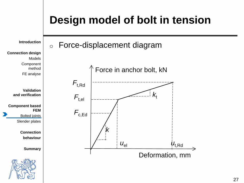
Design model of bolt in tension
o Force-displacement diagram
27
Force in anchor bolt, kN
Deformation, mm
uel ut,Rd
Ft,Rd
Ft,el
Fc,Ed
k
kt

Introduction
Connection design
Models
Component
method
FE analyse
Validation
and verification
Component based
FEM
Bolted joints
Slender plates
Connection
behaviour
Summary
Modelling of
T stub behaviour
• Research model
– Validation
• Design model
– Verification
28
Introduction
Connection design
Models
Component
method
FE analyse
Validation
and verification
Component based
FEM
Bolted joints
Slender plates
Connection
behaviour
Summary
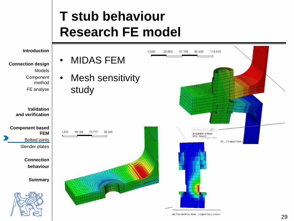
T stub behaviour
Research FE model
29
• MIDAS FEM
• Mesh sensitivity
study

Introduction
Connection design
Models
Component
method
FE analyse
Validation
and verification
Component based
FEM
Bolted joints
Slender plates
Connection
behaviour
Summary
Experiment with T stub
30
HEB300 HEB400
Introduction
Connection design
Models
Component
method
FE analyse
Validation
and verification
Component based
FEM
Bolted joints
Slender plates
Connection
behaviour
Summary
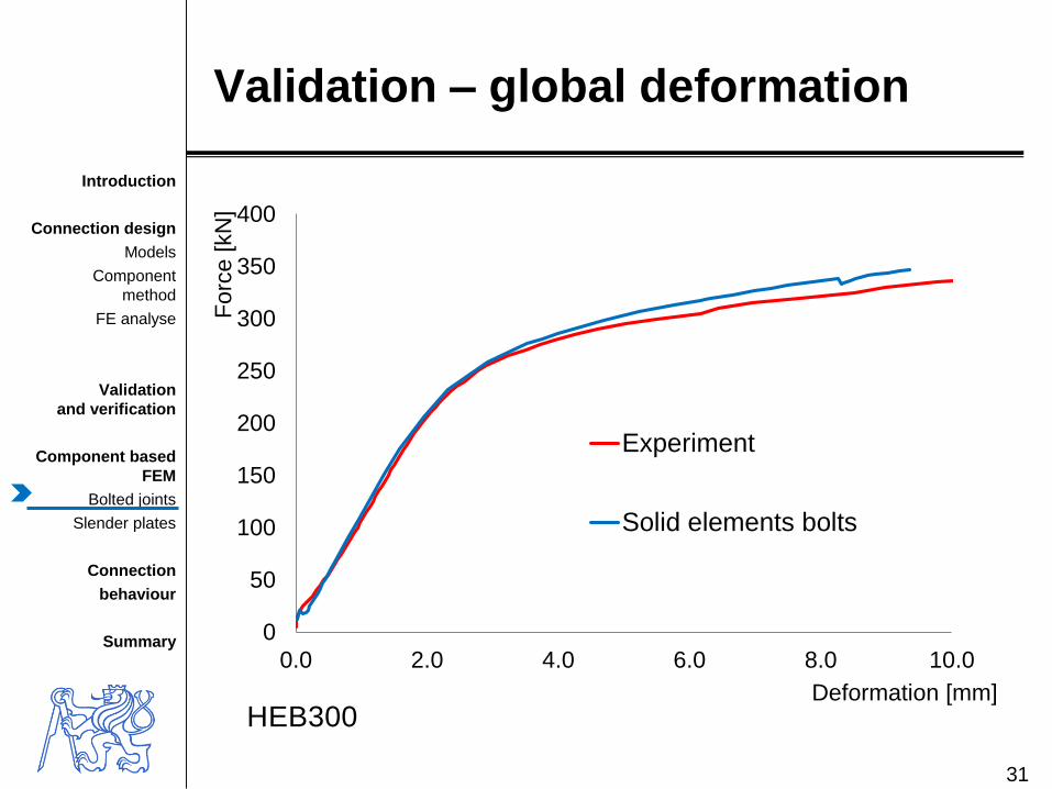
Validation – global deformation
31
0
50
100
150
200
250
300
350
400
0.0 2.0 4.0 6.0 8.0 10.0
Forc
e [
kN
]
Deformation [mm]
Experiment
Solid elements bolts
HEB300

Introduction
Connection design
Models
Component
method
FE analyse
Validation
and verification
Component based
FEM
Bolted joints
Slender plates
Connection
behaviour
Summary
32
0
50
100
150
200
250
300
350
0 1000 2000 3000 4000 5000 6000 7000 8000
Forc
e[k
N]
Deformation [mm/m]
Experiment-tenzometr11
Numerický model
Plate deformation in yield line
Validation – local deformation
Experiment, strain gauge 11
Research FEM
Introduction
Connection design
Models
Component
method
FE analyse
Validation
and verification
Component based
FEM
Bolted joints
Slender plates
Connection
behaviour
Summary
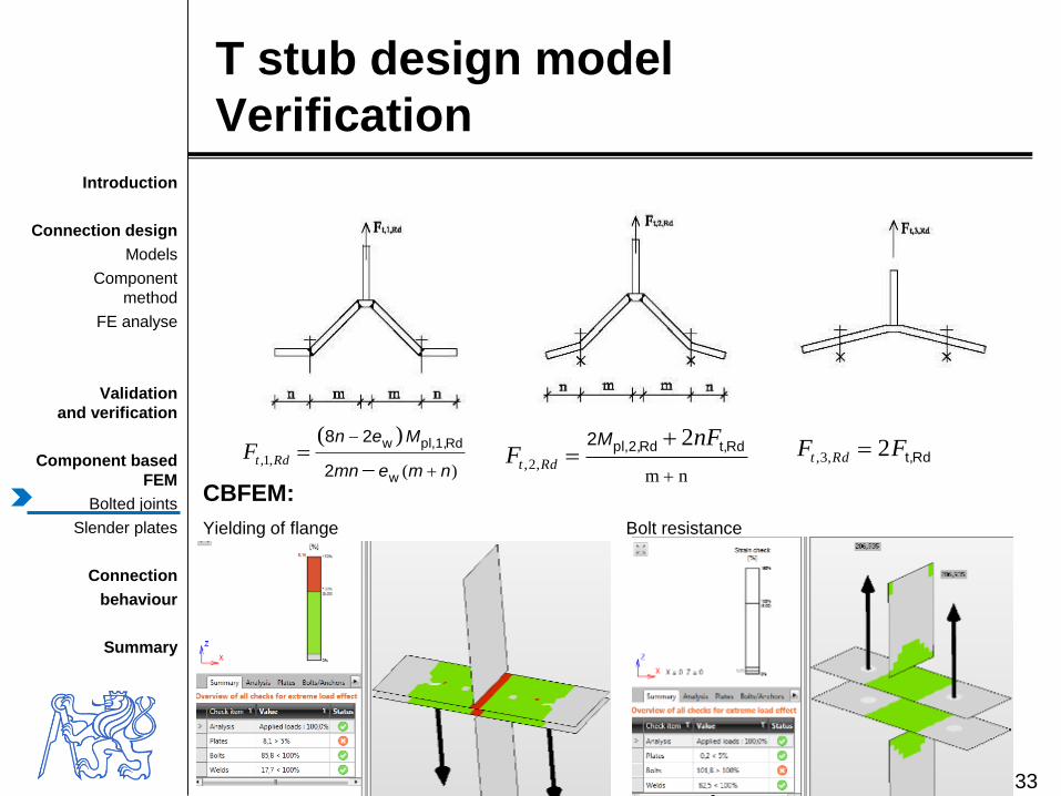
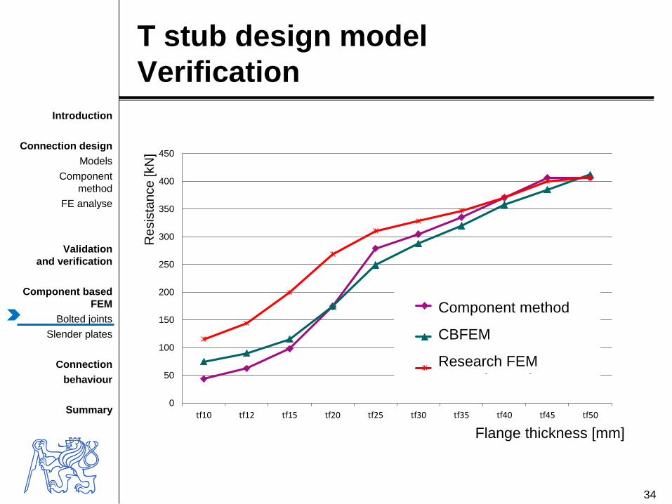
T stub design model
Verification
33
)(
)(,1,
nmemn
Men
w
Rdpl,1,w
2
28
RdtFnm
2,2,
Rdt,Rdpl,2,2 nFF Rdt
MRdt,FF Rdt 2,3,
CBFEM:
Yielding of flange Bolt resistance
Introduction
Connection design
Models
Component
method
FE analyse
Validation
and verification
Component based
FEM
Bolted joints
Slender plates
Connection
behaviour
Summary
34
T stub design model
Verification
0
50
100
150
200
250
300
350
400
450
tf10 tf12 tf15 tf20 tf25 tf30 tf35 tf40 tf45 tf50
Re
sis
tan
ce
[kN
]
Flange thickness [mm]
Metoda komponent
CBFEM
Validovaný vědecký 3D-FEM
Component method
CBFEM
Research FEM

Introduction
Connection design
Models
Component
method
FE analyse
Validation
and verification
Component based
FEM
Bolted joints
Slender plates
Connection
behaviour
Summary
35
T stub design model
Verification
0
50
100
150
200
250
300
350
400
450
500
0 50 100 150 200 250 300 350 400 450 500
Resis
tan
ce
CB
FE
M [
kN
]
Resistance - Component method [kN]
Parametr-tloušťka pásnice
Parametr-velikost šroubu
Parametr-materiál šroubu
Parametr-vzdálenost šroubů
Parametr-šířka T-průřezu
Variation of
Plate thickness
Bolt size
Bolt materiál
Bolt distance
T stub thickness

Introduction
Connection design
Models
Component
method
FE analyse
Validation
and verification
Component based
FEM
Bolted joints
Slender plates
Connection
behaviour
Summary
Design model
Slender plate in compression
36
• Column web
• Stiffeners

Introduction
Connection design
Models
Component
method
FE analyse
Validation
and verification
Component based
FEM
Bolted joints
Slender plates
Connection
behaviour
Summary
Research FEM
• Shell elements, true-stress true strain
material model, mesh sensitivity
• Geometrical and material nonlinear model
with imperfections (GMNIA)
• Imperfections based on 1st buckling mode
• Experiments – literature, own
• Code RFEM
37

Introduction
Connection design
Models
Component
method
FE analyse
Validation
and verification
Component based
FEM
Bolted joints
Slender plates
Connection
behaviour
Summary
Experimental research
• Material tests
• Flanges – 3x free edge, 3x partial stiffener, 3x fully stiffening
• Variation of – Stiffener thickness t
– Haunch geometry h and w
– Flange thickness tf and width bf
38

Introduction
Connection design
Models
Component
method
FE analyse
Validation
and verification
Component based
FEM
Bolted joints
Slender plates
Connection
behaviour
Summary
Stiffener with free edge
h = w = 400 mm, t = 4 mm and t = 6 mm
39

Introduction
Connection design
Models
Component
method
FE analyse
Validation
and verification
Component based
FEM
Bolted joints
Slender plates
Connection
behaviour
Summary
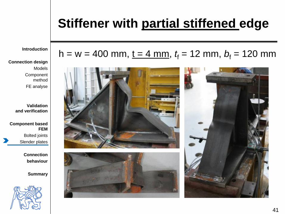
Stiffener with partial stiffened edge
h = w = 400 mm, t = 6 mm, tf = 6 mm, bf = 60 mm
40
Introduction
Connection design
Models
Component
method
FE analyse
Validation
and verification
Component based
FEM
Bolted joints
Slender plates
Connection
behaviour
Summary
Stiffener with partial stiffened edge
h = w = 400 mm, t = 4 mm, tf = 12 mm, bf = 120 mm
41
Introduction
Connection design
Models
Component
method
FE analyse
Validation
and verification
Component based
FEM
Bolted joints
Slender plates
Connection
behaviour
Summary
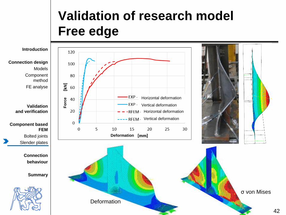
Validation of research model
Free edge
42
Deformation
σ von Mises
Horizontal deformation
Vertical deformation
Horizontal deformation
Vertical deformation
Deformation
Fo
rce
Introduction
Connection design
Models
Component
method
FE analyse
Validation
and verification
Component based
FEM
Bolted joints
Slender plates
Connection
behaviour
Summary
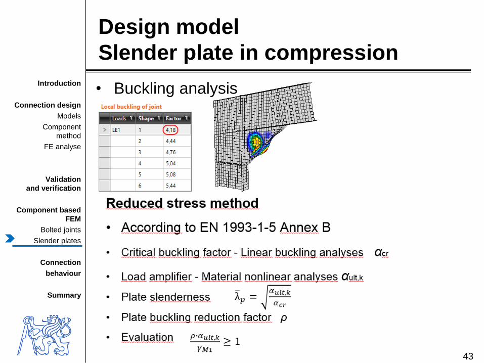
Design model
Slender plate in compression
43
• Buckling analysis

Introduction
Connection design
Models
Component
method
FE analyse
Validation
and verification
Component based
FEM
Bolted joints
Slender plates
Connection
behaviour
Summary
Connection behaviour
bolted connections of open section
• Generally
– Shear
– Tension
– Compression
• Research model
– Validation
• Design model
– Verification44
Introduction
Connection design
Models
Component
method
FE analyse
Validation
and verification
Component based
FEM
Bolted joints
Slender plates
Connection
behaviour
Summary
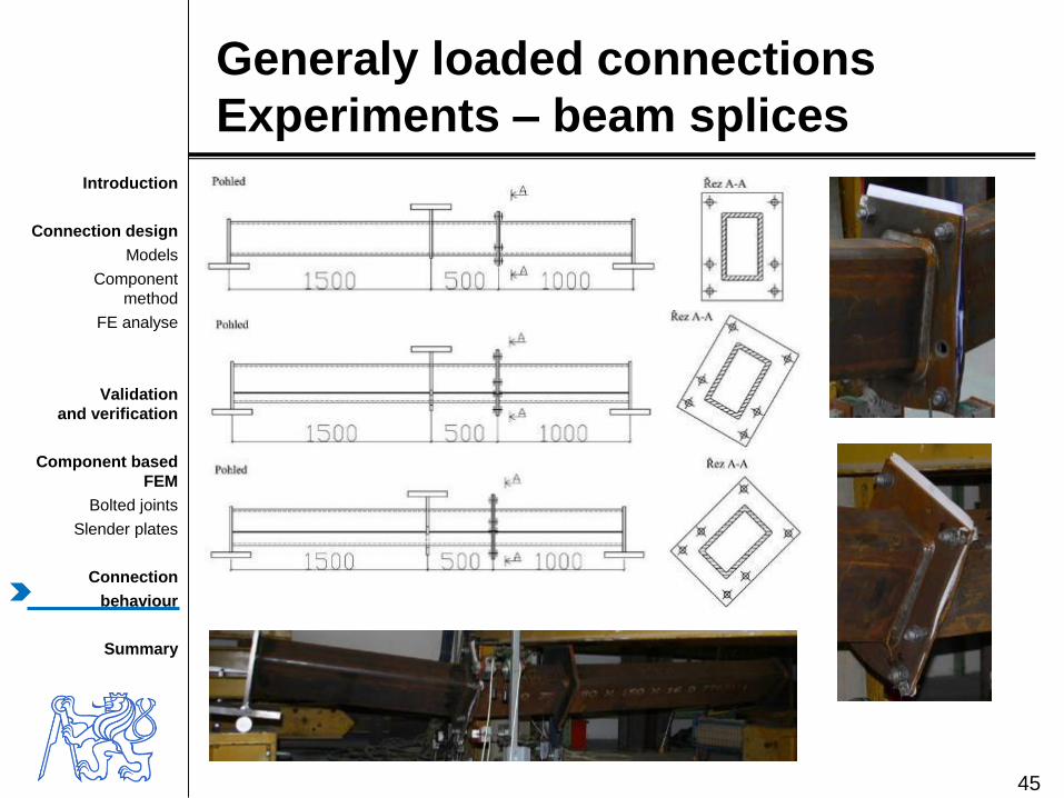
Generaly loaded connections
Experiments – beam splices
45

Introduction
Connection design
Models
Component
method
FE analyse
Validation
and verification
Component based
FEM
Bolted joints
Slender plates
Connection
behaviour
Summary
Generaly loaded connections
verification and validation
46
0
10
20
30
40
50
60
70
0 10 20 30 40 50 60 70 80 90 100
Ben
din
gm
om
en
t M
z[k
Nm
]
Bending moment My [kNm]
Experimenty Metoda komponent - lineární interakce
Metoda komponent - kvadratická interakce CBFEM
Experiments
Component method – quadratic interaction
Component method – linear interaction

Introduction
Connection design
Models
Component
method
FE analyse
Validation
and verification
Component based
FEM
Bolted joints
Slender plates
Connection
behaviour
Summary
Global behavior- sample 0°
47
0
10
20
30
40
50
60
70
80
90
100
0 20 40 60 80 100 120 140
Mo
men
t [k
Nm
]
Rotation [mrad]
CBFEM - 0°
Metoda komponent - 0°
Experiment - natočení 0°
Component method – 0°
Experiment – sample 0°

Introduction
Connection design
Models
Component
method
FE analyse
Validation
and verification
Component based
FEM
Bolted joints
Slender plates
Connection
behaviour
Summary
Prediction of
Deformation capacity
48
0
20
40
60
80
100
120
140
160
180
200
-50 50 150 250 350
Mo
me
nt [k
Nm
]
Rotation [mrad]
CM, Beg at al [20], strain 10%
CBFEM, lim. strain 3%
CBFEM, lim. strain 5%
CBFEM, lim. strain 10%
CBFEM, lim. strain 15%
CBFEM, lim. strain 20%
• Question of limiting straino Accuracy in case small deformations
o Moderated influence to resistance
o For resistance εCd = 5 %
o For deformation capacity εCd = 15 %

Introduction
Connection design
Models
Component
method
FE analyse
Validation
and verification
Component based
FEM
Bolted joints
Slender plates
Connection
behaviour
Summary
Prediction of
Deformation capacity
49
Question of not guaranteed values of yield strength of the structural steel
o Actual yield strength - EN 1998-1-8 cl. 6.2
Overstrenght factor gov = 1,25
fy,max ≤ 1,1 gov fy
0
20
40
60
80
100
120
140
160
180
200
0 50 100 150 200 250 300 350
Mo
me
nt
[kN
m]
Rotation [mrad]
CBFEM; fy = 235 MPa
CBFEM; fy = 1,1 x 235 MPa
CBFEM; fy = 1,25 x 235 MPa
CBFEM; fy = 1,35 x 235 MPa
CBFEM, fy = 1,5 x 235 MPa

Introduction
Connection design
Models
Component
method
FE analyse
Validation
and verification
Component based
FEM
Bolted joints
Slender plates
Connection
behaviour
Summary
Prediction
of global and local behaviour
Beam to column connection
• Full depth end plate 25 mm
• Rafter IPE 400
• Column HEA 320
• 12 bolts M24 8.8
• Haunch 700x300 mm
• Flange 15x150 mm
• Stiffeners P20
• Steel S355
50

Introduction
Connection design
Models
Component
method
FE analyse
Validation
and verification
Component based
FEM
Bolted joints
Slender plates
Connection
behaviour
Summary
IDEA StatiCa Connection
51
M = 180 kNm
Fi = 5,7 mrad
Si = 31,5
MNm/rad
Column web plastification
Moment, kNm
Natočení. mrad
Global and local behaviour

Introduction
Connection design
Models
Component
method
FE analyse
Validation
and verification
Component based
FEM
Bolted joints
Slender plates
Connection
behaviour
Summary
IDEA StatiCa Connection
52
M = 250 kNm
Fi = 10,7 mrad
Si = 23,4 MNm/rad
Column web full plastification
Moment, kNm
Natočení. mrad
Global and local behaviour

Introduction
Connection design
Models
Component
method
FE analyse
Validation
and verification
Component based
FEM
Bolted joints
Slender plates
Connection
behaviour
Summary
IDEA StatiCa Connection
53
M = 280 kNm
Fi = 43,6 mrad
Si = 6,4 MNm/rad
Further plastification
Moment, kNm
Natočení. mrad
Global and local behaviour

Introduction
Connection design
Models
Component
method
FE analyse
Validation
and verification
Component based
FEM
Bolted joints
Slender plates
Connection
behaviour
Summary
IDEA StatiCa Connection
54
Resistance reached - 5 % strain
Global and local behaviour
M = 290 kNm
Fi = 78,6 mrad
Si = 3,7 MNm/rad
Moment, kNm
Rotation, mrad

Introduction
Connection design
Models
Component
method
FE analyse
Validation
and verification
Component based
FEM
Bolted joints
Slender plates
Connection
behaviour
Summary
IDEA StatiCa Connection
55
Resistance
Initial stiffness
Deformation
capacity
Rotation, mrad
Moment, kNm
Global and local behaviour
To deformation capacity εCd = 15 %
For increase strength γov = 1,25
1,25 fy
Introduction
Connection design
Models
Component
method
FE analyse
Validation
and verification
Component based
FEM
Bolted joints
Slender plates
Connection
behaviour
Summary
Summary
• Results shows the good accuracy
of CBFEM verified to CM
• For higher
stiffness / resistance / deformation capacity
CBFEM compare to CM
verification by research FEM
validated to experiments
• Benchmark cases
and correct use of V&V
limits the improper use of model
• The high-quality education
the background
of design of pretty structural connections56
Introduction
Connection design
Models
Component
method
FE analyse
Validation
and verification
Component based
FEM
Bolted joints
Slender plates
Connection
behaviour
Summary
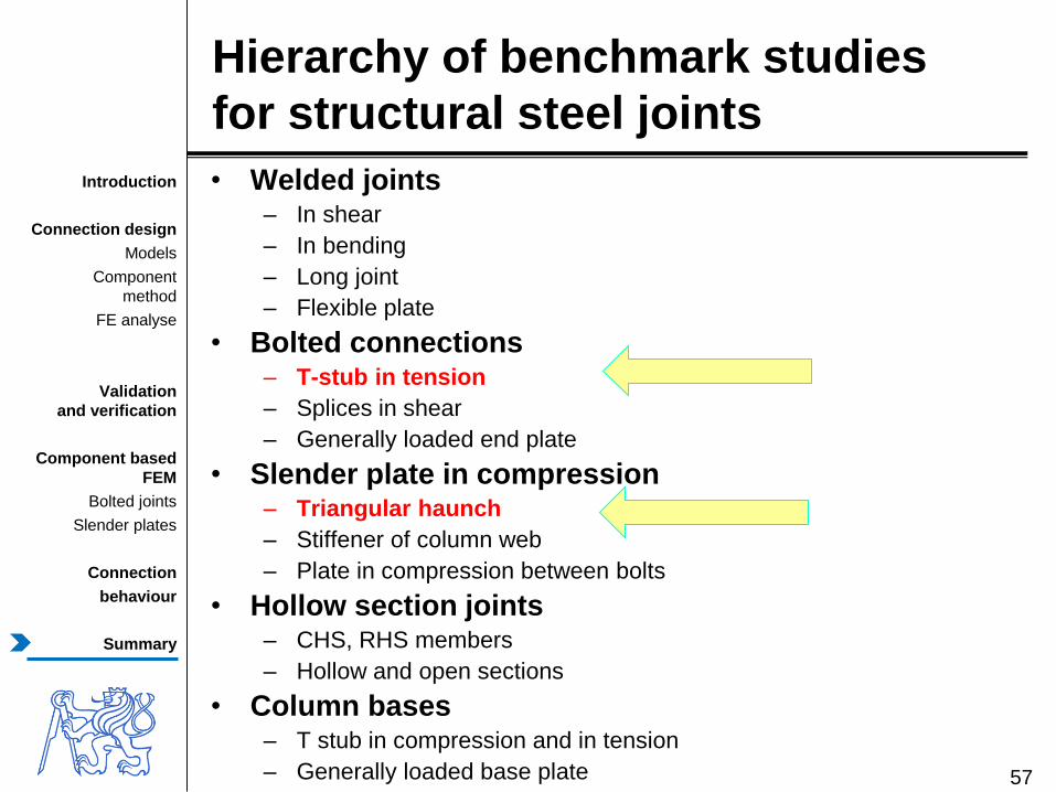
Hierarchy of benchmark studies
for structural steel joints
• Welded joints – In shear
– In bending
– Long joint
– Flexible plate
• Bolted connections– T-stub in tension
– Splices in shear
– Generally loaded end plate
• Slender plate in compression – Triangular haunch
– Stiffener of column web
– Plate in compression between bolts
• Hollow section joints– CHS, RHS members
– Hollow and open sections
• Column bases– T stub in compression and in tension
– Generally loaded base plate 57

Introduction
Connection design
Models
Component
method
FE analyse
Validation
and verification
Component based
FEM
Bolted joints
Slender plates
Connection
behaviour
Summary
What are the predictive
capabilities of our computer simulations?
„Essentially,
all models
are wrong,
but
some
are useful’’
Box G.E.P., Draper N.R. (1987)
Empirical model-building and response surfaces, John Wiley & Sons., pp. 669.
58
Introduction
Connection design
Models
Component
method
FE analyse
Validation
and verification
Component based
FEM
Bolted joints
Slender plates
Connection
behaviour
Summary
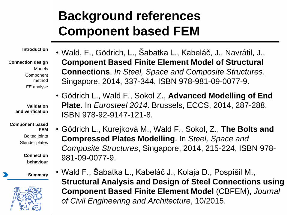
Background references
Component based FEM
• Wald, F., Gödrich, L., Šabatka L., Kabeláč, J., Navrátil, J.,
Component Based Finite Element Model of Structural
Connections. In Steel, Space and Composite Structures.
Singapore, 2014, 337-344, ISBN 978-981-09-0077-9.
• Gödrich L., Wald F., Sokol Z., Advanced Modelling of End
Plate. In Eurosteel 2014. Brussels, ECCS, 2014, 287-288,
ISBN 978-92-9147-121-8.
• Gödrich L., Kurejková M., Wald F., Sokol, Z., The Bolts and
Compressed Plates Modelling. In Steel, Space and
Composite Structures, Singapore, 2014, 215-224, ISBN 978-
981-09-0077-9.
• Wald F., Šabatka L., Kabeláč J., Kolaja D., Pospíšil M.,
Structural Analysis and Design of Steel Connections using
Component Based Finite Element Model (CBFEM), Journal
of Civil Engineering and Architecture, 10/2015.

Thank you for your attention
Lukáš Gödrich
Czech Technical University in Prague
URL: www.ocel-drevo.fsv.cvut.cz


![Finite [Mayjune2013]](https://img.pdfslide.tips/doc/110x75/55cf8d2c5503462b1392af25/finite-mayjune2013.jpg)