Embed Size (px)
Citation preview
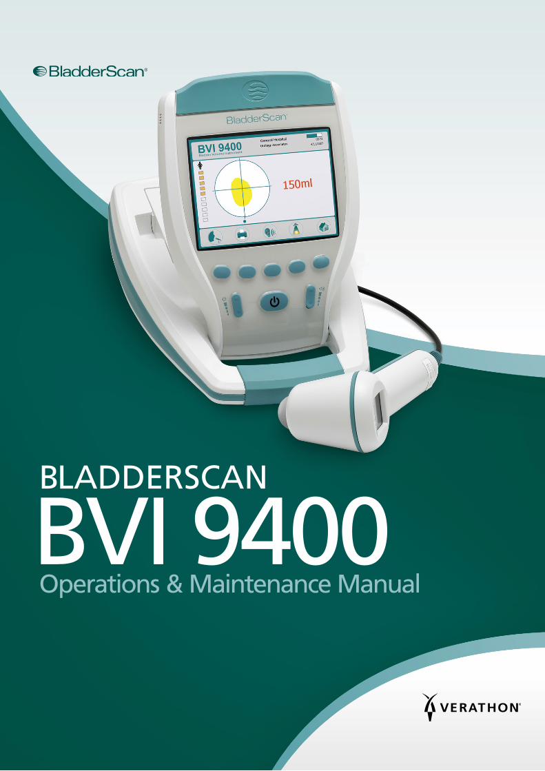
BLADDERSCAN
BVI 9400Operations & Maintenance Manual

0900‑4412‑06‑60

BLADDERSCAN
BVI 9400Operations & Maintenance Manual
Effective: September 29, 2017
Caution: Federal (United States) law restricts this device to sale by or on the order of a physician.
CONTACT INFORMATIONTo obtain additional information regarding your BladderScan system,
please contact Verathon® Customer Care or visit verathon.com/support.
Verathon Inc.
20001 North Creek Parkway Bothell, WA 98011 U.S.A.
800.331.2313 (US and Canada only) 425.867.1348
Fax: 425.883.2896 verathon.com
Verathon Medical (Europe) B.V.
Willem Fenengastraat 13 1096 BL Amsterdam
The Netherlands Tel: +31 (0) 20 210 30 91 Fax: +31 (0) 20 210 30 92
verathon.com
0123
Copyright © 2017 by Verathon Inc. All rights reserved. No part of this manual may be copied or transmitted by any method without the express written consent of Verathon Inc.
Verathon, the Verathon torch symbol, BladderScan, the BladderScan symbol, Scan Point, and NeuralHarmonics are trademarks or registered trademarks, and Total Reliability Plan is a service mark of Verathon Inc. Bluetooth® word mark and logos are owned by the Bluetooth SIG, Inc. and any use of such marks by Verathon is under license. All other brand and product names are trademarks or registered trademarks of their respective owners.
Information in this manual may change at any time without notice. For the most up‑to‑date information, see the documentation available at verathon.com/product‑documentation.
iOperations & Maintenance Manual: Table of Contents
TABLE OF CONTENTS
IMPORTANT INFORMATION .................................................................................................................................1
Overview ............................................................................................................................................................1
Product Description .........................................................................................................................................1
Notice to All Users ...........................................................................................................................................2
Statement of Prescription .................................................................................................................................2
Statement of Intended Use ..............................................................................................................................2
Essential Performance ......................................................................................................................................2
Safety Information ..............................................................................................................................................2
Biological Safety ..............................................................................................................................................2
Contraindications .............................................................................................................................................2
Cautions & Warnings .......................................................................................................................................3
INTRODUCTION ....................................................................................................................................................7
Components & Features ......................................................................................................................................7
Probe Components ..........................................................................................................................................8
Console Components ......................................................................................................................................9
Battery Charger/Wireless Hub Components ...................................................................................................10
System Components & Accessories ................................................................................................................... 11
Icons & Buttons ................................................................................................................................................ 12
Console Display Icons ..................................................................................................................................... 12
Variable Button Functions .............................................................................................................................. 13
Button Functions for Each Display Screen .......................................................................................................14
Display Screens ................................................................................................................................................. 17
Sleep Mode ......................................................................................................................................................33
Histogram of Cost Savings ................................................................................................................................33
ii
SETTING UP ........................................................................................................................................................34
Procedure 1. Perform the Initial Inspection ...............................................................................................34
Procedure 2. Set Up the Battery ...............................................................................................................35
Procedure 3. Attach the Probe to the Console ..........................................................................................37
Procedure 4. Program the Facility Name ...................................................................................................38
Procedure 5. Set the Date and Time .........................................................................................................40
Procedure 6. Load the Thermal Paper ....................................................................................................... 41
Procedure 7. Attach the Instrument to a Medical Cart (Optional) ..............................................................42
Procedure 8. Install Scan Point with QuickPrint (Optional) .........................................................................44
Procedure 9. Watch the Onboard Tutorial .................................................................................................44
USING THE DEVICE .............................................................................................................................................45
Procedure 1. Prepare for the Exam ...........................................................................................................46
Procedure 2. Measure Bladder Volume .....................................................................................................47
Procedure 3. Save, Review, & Print Exam Results .......................................................................................50
Procedure 4. Delete a Saved Exam ........................................................................................................... 51
CLEANING & MAINTENANCE .............................................................................................................................52
Procedure 1. Clean & Disinfect the Instrument ..........................................................................................53
Regular Inspections ...........................................................................................................................................54
Maintenance .....................................................................................................................................................55
Procedure 1. Run a Self‑Test .....................................................................................................................55
Procedure 2. Update the Software ...........................................................................................................56
Procedure 3. Calibrate the Probe Using the Scan Point System ..................................................................58
Device Disposal .................................................................................................................................................61
iiiOperations & Maintenance Manual: Table of Contents
TROUBLESHOOTING ...........................................................................................................................................62
Help Resources .................................................................................................................................................62
Device Repair ....................................................................................................................................................62
Warranty ..........................................................................................................................................................62
Troubleshooting Procedures ..............................................................................................................................63
Procedure 1. Troubleshoot Scan Point Connection ....................................................................................63
Procedure 2. Troubleshoot Power Issues ...................................................................................................64
Procedure 3. Instrument Too Hot ..............................................................................................................64
Procedure 4. Clear a Paper Jam ................................................................................................................64
PRODUCT SPECIFICATIONS .................................................................................................................................65
Component Specifications ................................................................................................................................65
Console & Probe Specifications ......................................................................................................................65
Battery Specifications .....................................................................................................................................68
Battery Charger/Wireless Hub Specifications ..................................................................................................69
Bluetooth Wireless Technology ..........................................................................................................................70
Electromagnetic Compatibility ...........................................................................................................................70
Electromagnetic Emissions .............................................................................................................................70
Electromagnetic Immunity .............................................................................................................................71
Recommended Separation Distances ..............................................................................................................73
Accessory Conformance to Standards.............................................................................................................73
GLOSSARY ...........................................................................................................................................................74


1Operations & Maintenance Manual: Important Information
IMPORTANT INFORMATION
OVERVIEW
PRODUCT DESCRIPTIONThe BladderScan BVI 9400, with NeuralHarmonics™ technology, is a portable ultrasound instrument that provides a noninvasive measurement of urinary bladder volume. The device consists of an ultrasound probe that scans the patient’s bladder and a compact, battery‑operated console that provides measurement‑related information.
BladderScan instruments are quick and easy to use. When the user presses the Scan button, within seconds the BVI 9400 measures ultrasonic reflections on multiple planes inside the body and produces a three‑dimensional image. Based on this image, the BVI 9400 calculates and displays the bladder volume. A sonographer is not required.
NeuralHarmonics technology in the BVI 9400 sharpens accuracy and accelerates speed of measurement. Volume measurements made with NeuralHarmonics technology are more accurate than those made with conventional two‑dimensional ultrasound, as they are based on a more complex, multifaceted image of the bladder. This technology–applying multispectral analysis to a robust data set–helps reduce margin of error and minimize uncertainty in essential measurements of bladder function.
BladderScan BVI 9400 measurements can be printed via an onboard printer or transmitted using HIPAA‑compliant Scan Point® image management technology (optional) to your office or facility computer for viewing, printing, or archiving.
After a scan has been taken, a unique aiming icon guides the operator to optimal probe placement with a comprehensive, three‑dimensional display which shows the bladder in two cross‑sectional images verifying a complete scan has been achieved. Bladder volume, patient type, directional aiming with real‑time feedback, battery status, and usage rate indicators are all displayed on the device’s main display. The BladderScan BVI 9400 contains an onboard thermal printer that allows the user to print exam results quickly with the press of a button.
A calibration system, consisting of a tank and target, allows the user to easily calibrate the device by scanning a known target.
Optionally, exam results may be transmitted to a personal computer running Scan Point with QuickPrint software via a proprietary wireless connection. Scan Point with QuickPrint allows the user to archive data, calibrate the device, update software, print, and transfer data through a web‑based interface.
The BladderScan BVI 9400 system includes a battery charger for the custom, user‑replaceable lithium‑ion battery used in the system.
The BladderScan BVI 9400 may be mounted on a mobile cart, which holds the instrument securely and provides storage for ultrasound gel and other accessories.
2
NOTICE TO ALL USERSThe BladderScan BVI 9400 should be used only by individuals who have been trained and authorized by a physician or the institution providing patient care. All users must read this entire manual prior to using the BladderScan BVI 9400. Do not attempt to operate this instrument until you thoroughly understand all instructions and procedures in this manual. Failure to comply with these instructions may compromise the performance of the device and the reliability of its measurements.
STATEMENT OF PRESCRIPTIONCaution: Federal (United States) law restricts this device to sale by or on the order of a physician.
STATEMENT OF INTENDED USEThe BladderScan BVI 9400 projects ultrasound energy through the lower abdomen of the patient to obtain an image of the bladder, which is used to calculate bladder volume noninvasively.
ESSENTIAL PERFORMANCEEssential performance is the system performance necessary to achieve freedom from unacceptable risk. The essential performance of the BladderScan BVI 9400 system is to produce ultrasonic output energy, display ultrasonic images, and display numerical values for bladder volume. The system has a temperature‑controlled transducer assembly.
SAFETY INFORMATION
BIOLOGICAL SAFETYTo date, exposure to pulsed diagnostic ultrasound has not been shown to produce adverse effects. However, ultrasound should be used only by medical professionals when clinically indicated, using the lowest possible exposure times indicated by clinical need.
The ultrasound output power of the BladderScan BVI 9400 is not user adjustable and is limited to the minimum level necessary for effective performance. Data on acoustic output levels can be found in the Product Specifications.
CONTRAINDICATIONSThe BladderScan BVI 9400 is not intended for fetal use or for use on pregnant patients.
3Operations & Maintenance Manual: Important Information
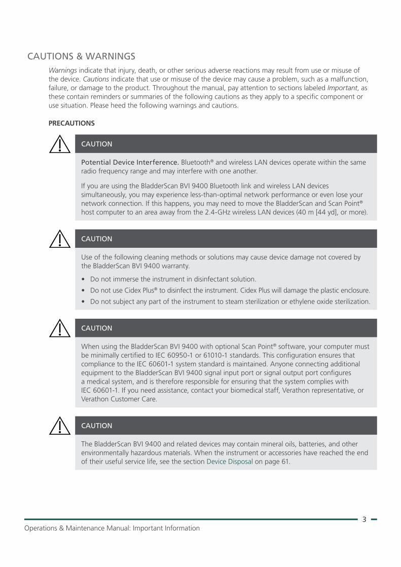
CAUTIONS & WARNINGSWarnings indicate that injury, death, or other serious adverse reactions may result from use or misuse of the device. Cautions indicate that use or misuse of the device may cause a problem, such as a malfunction, failure, or damage to the product. Throughout the manual, pay attention to sections labeled Important, as these contain reminders or summaries of the following cautions as they apply to a specific component or use situation. Please heed the following warnings and cautions.
PRECAUTIONS
Potential Device Interference. Bluetooth® and wireless LAN devices operate within the same radio frequency range and may interfere with one another.
If you are using the BladderScan BVI 9400 Bluetooth link and wireless LAN devices simultaneously, you may experience less‑than‑optimal network performance or even lose your network connection. If this happens, you may need to move the BladderScan and Scan Point® host computer to an area away from the 2.4‑GHz wireless LAN devices (40 m [44 yd], or more).
CAUTION
Use of the following cleaning methods or solutions may cause device damage not covered by the BladderScan BVI 9400 warranty.
• Do not immerse the instrument in disinfectant solution.
• Do not use Cidex Plus® to disinfect the instrument. Cidex Plus will damage the plastic enclosure.
• Do not subject any part of the instrument to steam sterilization or ethylene oxide sterilization.
CAUTION
When using the BladderScan BVI 9400 with optional Scan Point® software, your computer must be minimally certified to IEC 60950‑1 or 61010‑1 standards. This configuration ensures that compliance to the IEC 60601‑1 system standard is maintained. Anyone connecting additional equipment to the BladderScan BVI 9400 signal input port or signal output port configures a medical system, and is therefore responsible for ensuring that the system complies with IEC 60601‑1. If you need assistance, contact your biomedical staff, Verathon representative, or Verathon Customer Care.
CAUTION
The BladderScan BVI 9400 and related devices may contain mineral oils, batteries, and other environmentally hazardous materials. When the instrument or accessories have reached the end of their useful service life, see the section Device Disposal on page 61.
CAUTION
4
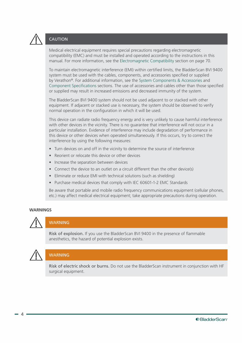
Medical electrical equipment requires special precautions regarding electromagnetic compatibility (EMC) and must be installed and operated according to the instructions in this manual. For more information, see the Electromagnetic Compatibility section on page 70.
To maintain electromagnetic interference (EMI) within certified limits, the BladderScan BVI 9400 system must be used with the cables, components, and accessories specified or supplied by Verathon®. For additional information, see the System Components & Accessories and Component Specifications sections. The use of accessories and cables other than those specified or supplied may result in increased emissions and decreased immunity of the system.
The BladderScan BVI 9400 system should not be used adjacent to or stacked with other equipment. If adjacent or stacked use is necessary, the system should be observed to verify normal operation in the configuration in which it will be used.
This device can radiate radio frequency energy and is very unlikely to cause harmful interference with other devices in the vicinity. There is no guarantee that interference will not occur in a particular installation. Evidence of interference may include degradation of performance in this device or other devices when operated simultaneously. If this occurs, try to correct the interference by using the following measures:
• Turn devices on and off in the vicinity to determine the source of interference
• Reorient or relocate this device or other devices
• Increase the separation between devices
• Connect the device to an outlet on a circuit different than the other device(s)
• Eliminate or reduce EMI with technical solutions (such as shielding)
• Purchase medical devices that comply with IEC 60601‑1‑2 EMC Standards
Be aware that portable and mobile radio frequency communications equipment (cellular phones, etc.) may affect medical electrical equipment; take appropriate precautions during operation.
CAUTION
WARNINGS
Risk of explosion. If you use the BladderScan BVI 9400 in the presence of flammable anesthetics, the hazard of potential explosion exists.
WARNING
Risk of electric shock or burns. Do not use the BladderScan instrument in conjunction with HF surgical equipment.
WARNING
5Operations & Maintenance Manual: Important Information
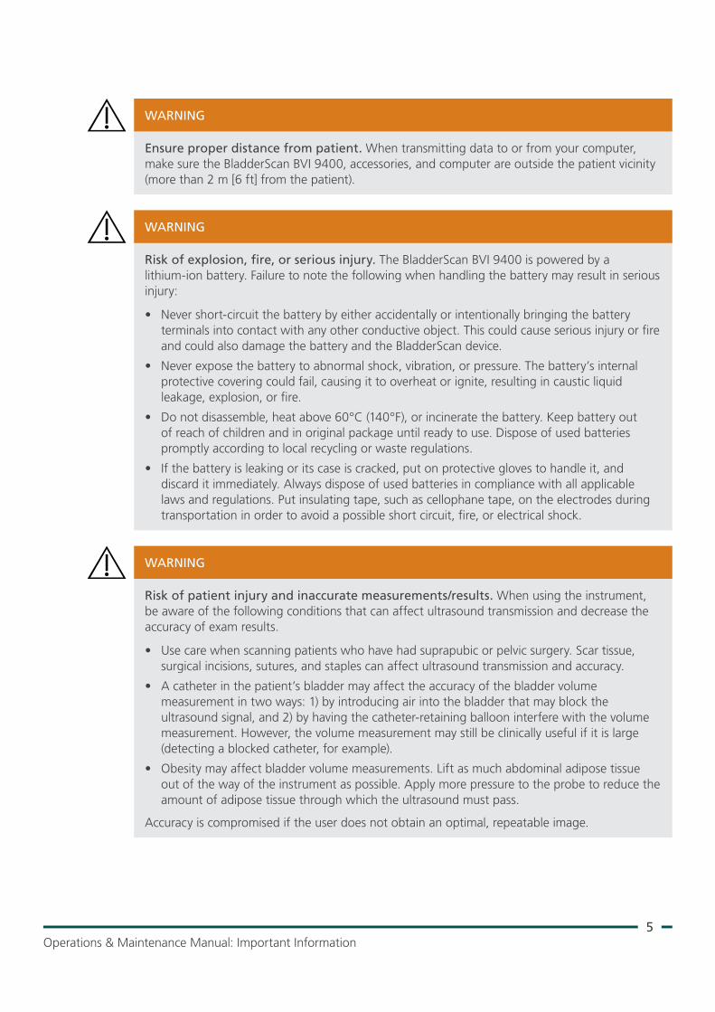
Ensure proper distance from patient. When transmitting data to or from your computer, make sure the BladderScan BVI 9400, accessories, and computer are outside the patient vicinity (more than 2 m [6 ft] from the patient).
WARNING
Risk of explosion, fire, or serious injury. The BladderScan BVI 9400 is powered by a lithium‑ion battery. Failure to note the following when handling the battery may result in serious injury:
• Never short‑circuit the battery by either accidentally or intentionally bringing the battery terminals into contact with any other conductive object. This could cause serious injury or fire and could also damage the battery and the BladderScan device.
• Never expose the battery to abnormal shock, vibration, or pressure. The battery’s internal protective covering could fail, causing it to overheat or ignite, resulting in caustic liquid leakage, explosion, or fire.
• Do not disassemble, heat above 60°C (140°F), or incinerate the battery. Keep battery out of reach of children and in original package until ready to use. Dispose of used batteries promptly according to local recycling or waste regulations.
• If the battery is leaking or its case is cracked, put on protective gloves to handle it, and discard it immediately. Always dispose of used batteries in compliance with all applicable laws and regulations. Put insulating tape, such as cellophane tape, on the electrodes during transportation in order to avoid a possible short circuit, fire, or electrical shock.
WARNING
Risk of patient injury and inaccurate measurements/results. When using the instrument, be aware of the following conditions that can affect ultrasound transmission and decrease the accuracy of exam results.
• Use care when scanning patients who have had suprapubic or pelvic surgery. Scar tissue, surgical incisions, sutures, and staples can affect ultrasound transmission and accuracy.
• A catheter in the patient’s bladder may affect the accuracy of the bladder volume measurement in two ways: 1) by introducing air into the bladder that may block the ultrasound signal, and 2) by having the catheter‑retaining balloon interfere with the volume measurement. However, the volume measurement may still be clinically useful if it is large (detecting a blocked catheter, for example).
• Obesity may affect bladder volume measurements. Lift as much abdominal adipose tissue out of the way of the instrument as possible. Apply more pressure to the probe to reduce the amount of adipose tissue through which the ultrasound must pass.
Accuracy is compromised if the user does not obtain an optimal, repeatable image.
WARNING

6
Do not use the BladderScan BVI 9400 on:
• A patient who has open skin or wounds in the suprapubic area.
• A patient with ascites.
• A pregnant patient.
WARNING
Potential patient hazard. To date, exposure to low‑power, pulsed diagnostic ultrasound has not been shown to produce adverse effects. However, medical professionals should use ultrasound only when clinically indicated, using the lowest exposure times possible to obtain accurate measurements. The ultrasonic output of the BladderScan BVI 9400 is not user adjustable and is limited to the minimum level necessary for effective performance. For more information about the acoustic output levels of this device, see the chapter Product Specifications on page 65.
WARNING
This product may only be cleaned and disinfected by using the approved processes provided in this manual. Cleaning and disinfection methods listed are recommended by Verathon® based on compatibility with component materials.
WARNING
Availability of cleaning and disinfection products varies by country, and Verathon is unable to test products in every market. For more information, please contact Verathon Customer Care or your local representative. For additional contact information, visit verathon.com/support.
WARNING
Ensure that you follow the manufacturer’s instructions for handling and disposing of the cleaning and disinfection solutions provided in this manual.
WARNING
Cleaning is critical to ensuring the component is ready for disinfection. Failure to properly clean the device could result in a contaminated instrument after completing the disinfection procedure.
WARNING
7Operations & Maintenance Manual: Introduction
INTRODUCTION
COMPONENTS & FEATURESThe BladderScan BVI 9400 is designed for simple, intuitive operation. However, to ensure safe and effective operation, do the following before using the device:
• Familiarize yourself with the contents of this manual.
• Watch the onboard tutorial provided on the instrument.
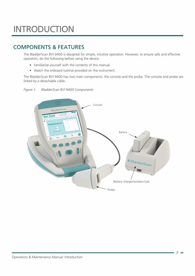
The BladderScan BVI 9400 has two main components: the console and the probe. The console and probe are linked by a detachable cable.
Figure 1. BladderScan BVI 9400 Components
Console
Probe
Battery charger/wireless hub
Battery
8
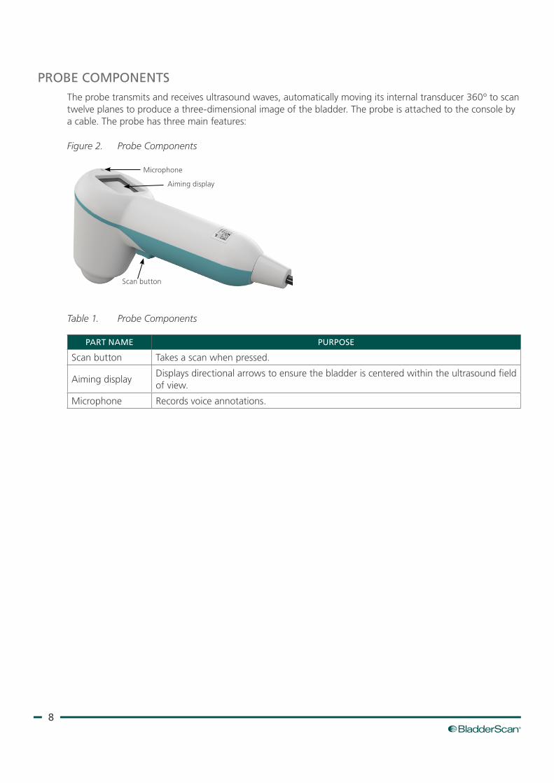
PROBE COMPONENTSThe probe transmits and receives ultrasound waves, automatically moving its internal transducer 360º to scan twelve planes to produce a three‑dimensional image of the bladder. The probe is attached to the console by a cable. The probe has three main features:
Figure 2. Probe Components
Scan button
Aiming display
Microphone
Table 1. Probe Components
PART NAME PURPOSE
Scan button Takes a scan when pressed.
Aiming displayDisplays directional arrows to ensure the bladder is centered within the ultrasound field of view.
Microphone Records voice annotations.
9Operations & Maintenance Manual: Introduction
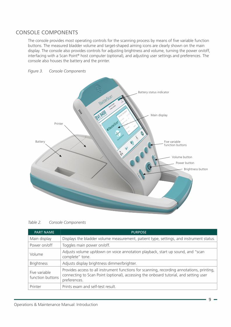
CONSOLE COMPONENTSThe console provides most operating controls for the scanning process by means of five variable function buttons. The measured bladder volume and target‑shaped aiming icons are clearly shown on the main display. The console also provides controls for adjusting brightness and volume, turning the power on/off, interfacing with a Scan Point® host computer (optional), and adjusting user settings and preferences. The console also houses the battery and the printer.
Figure 3. Console Components
Battery status indicator
Main display
Battery
Brightness button
Power button
Printer
Volume button
Five variable function buttons
Table 2. Console Components
PART NAME PURPOSE
Main display Displays the bladder volume measurement, patient type, settings, and instrument status.
Power on/off Toggles main power on/off.
VolumeAdjusts volume up/down on voice annotation playback, start up sound, and “scan complete” tone.
Brightness Adjusts display brightness dimmer/brighter.
Five variable function buttons
Provides access to all instrument functions for scanning, recording annotations, printing, connecting to Scan Point (optional), accessing the onboard tutorial, and setting user preferences.
Printer Prints exam and self‑test result.
10
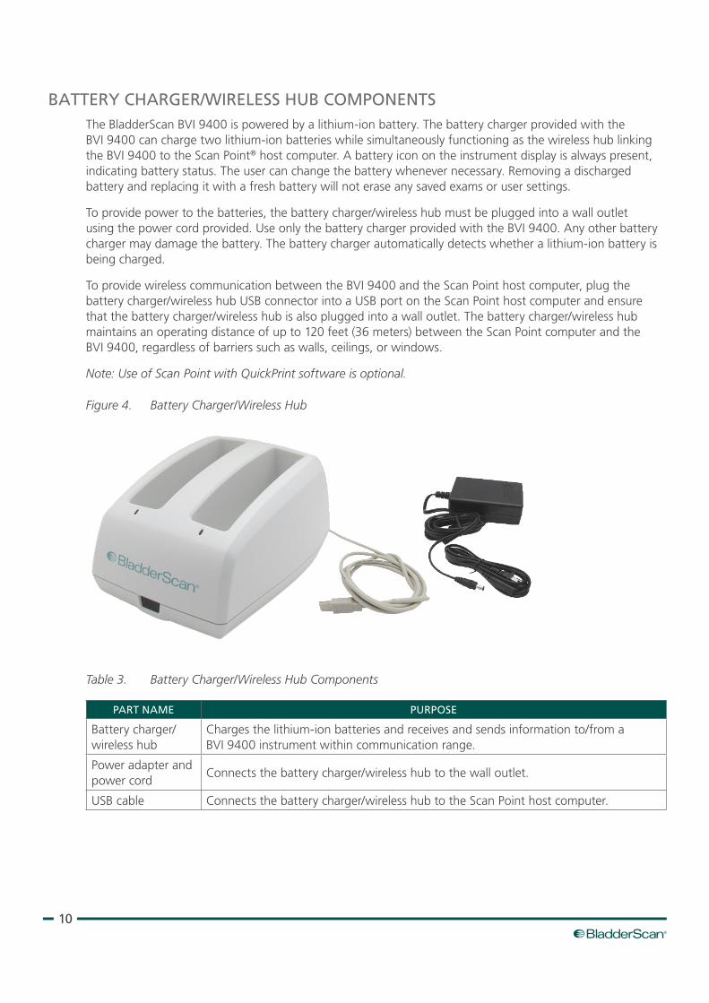
BATTERY CHARGER/WIRELESS HUB COMPONENTSThe BladderScan BVI 9400 is powered by a lithium‑ion battery. The battery charger provided with the BVI 9400 can charge two lithium‑ion batteries while simultaneously functioning as the wireless hub linking the BVI 9400 to the Scan Point® host computer. A battery icon on the instrument display is always present, indicating battery status. The user can change the battery whenever necessary. Removing a discharged battery and replacing it with a fresh battery will not erase any saved exams or user settings.
To provide power to the batteries, the battery charger/wireless hub must be plugged into a wall outlet using the power cord provided. Use only the battery charger provided with the BVI 9400. Any other battery charger may damage the battery. The battery charger automatically detects whether a lithium‑ion battery is being charged.
To provide wireless communication between the BVI 9400 and the Scan Point host computer, plug the battery charger/wireless hub USB connector into a USB port on the Scan Point host computer and ensure that the battery charger/wireless hub is also plugged into a wall outlet. The battery charger/wireless hub maintains an operating distance of up to 120 feet (36 meters) between the Scan Point computer and the BVI 9400, regardless of barriers such as walls, ceilings, or windows.
Note: Use of Scan Point with QuickPrint software is optional.
Figure 4. Battery Charger/Wireless Hub
Table 3. Battery Charger/Wireless Hub Components
PART NAME PURPOSE
Battery charger/wireless hub
Charges the lithium‑ion batteries and receives and sends information to/from a BVI 9400 instrument within communication range.
Power adapter and power cord
Connects the battery charger/wireless hub to the wall outlet.
USB cable Connects the battery charger/wireless hub to the Scan Point host computer.
11Operations & Maintenance Manual: Introduction
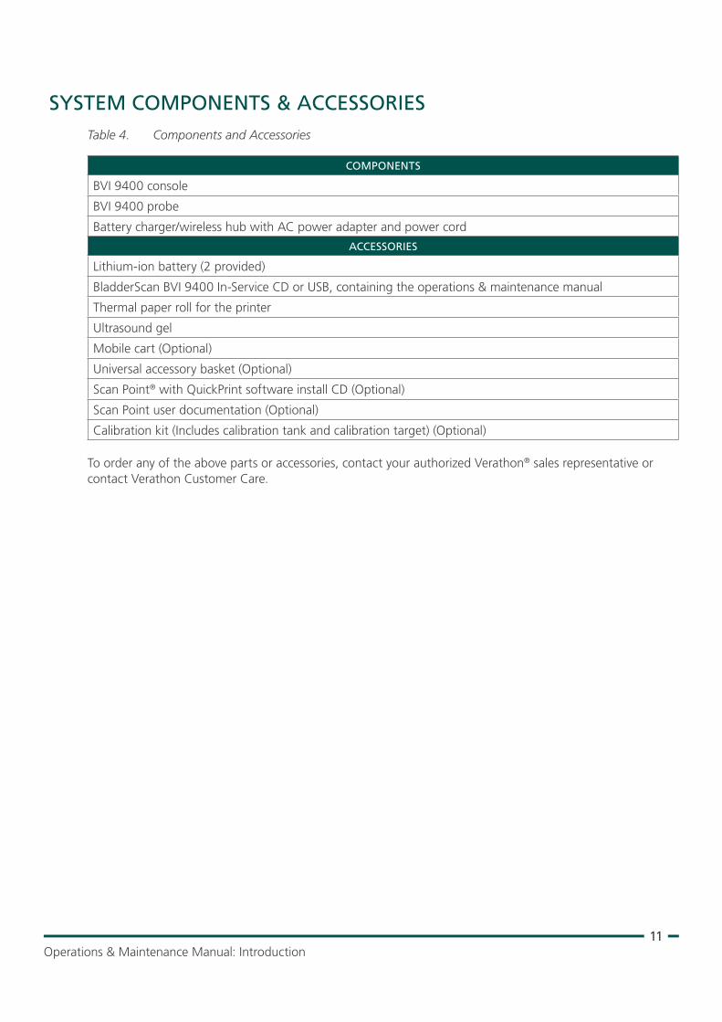
SYSTEM COMPONENTS & ACCESSORIESTable 4. Components and Accessories
COMPONENTS
BVI 9400 console
BVI 9400 probe
Battery charger/wireless hub with AC power adapter and power cord
ACCESSORIES
Lithium‑ion battery (2 provided)
BladderScan BVI 9400 In‑Service CD or USB, containing the operations & maintenance manual
Thermal paper roll for the printer
Ultrasound gel
Mobile cart (Optional)
Universal accessory basket (Optional)
Scan Point® with QuickPrint software install CD (Optional)
Scan Point user documentation (Optional)
Calibration kit (Includes calibration tank and calibration target) (Optional)
To order any of the above parts or accessories, contact your authorized Verathon® sales representative or contact Verathon Customer Care.
12
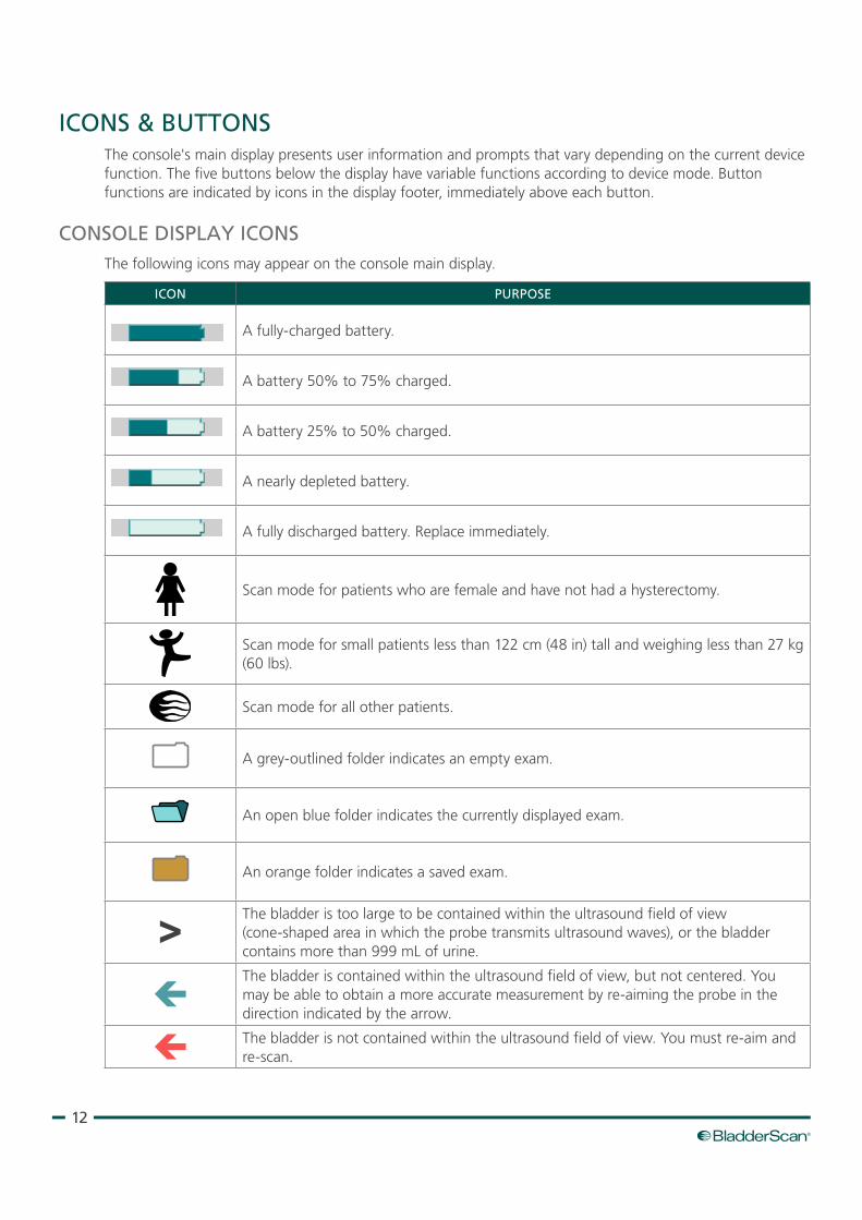
ICONS & BUTTONSThe console's main display presents user information and prompts that vary depending on the current device function. The five buttons below the display have variable functions according to device mode. Button functions are indicated by icons in the display footer, immediately above each button.
CONSOLE DISPLAY ICONSThe following icons may appear on the console main display.
ICON PURPOSE
A fully‑charged battery.
A battery 50% to 75% charged.
A battery 25% to 50% charged.
A nearly depleted battery.
A fully discharged battery. Replace immediately.
Scan mode for patients who are female and have not had a hysterectomy.
Scan mode for small patients less than 122 cm (48 in) tall and weighing less than 27 kg (60 lbs).
Scan mode for all other patients.
A grey‑outlined folder indicates an empty exam.
An open blue folder indicates the currently displayed exam.
An orange folder indicates a saved exam.
The bladder is too large to be contained within the ultrasound field of view (cone‑shaped area in which the probe transmits ultrasound waves), or the bladder contains more than 999 mL of urine.
The bladder is contained within the ultrasound field of view, but not centered. You may be able to obtain a more accurate measurement by re‑aiming the probe in the direction indicated by the arrow.
The bladder is not contained within the ultrasound field of view. You must re‑aim and re‑scan.
13Operations & Maintenance Manual: Introduction
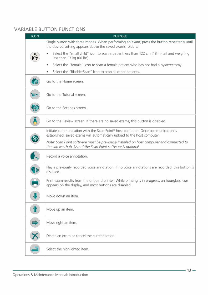
VARIABLE BUTTON FUNCTIONSICON PURPOSE
Single button with three modes. When performing an exam, press the button repeatedly until the desired setting appears above the saved exams folders:
• Select the “small child” icon to scan a patient less than 122 cm (48 in) tall and weighing less than 27 kg (60 lbs).
• Select the “female” icon to scan a female patient who has not had a hysterectomy.
• Select the “BladderScan” icon to scan all other patients.
Go to the Home screen.
Go to the Tutorial screen.
Go to the Settings screen.
Go to the Review screen. If there are no saved exams, this button is disabled.
Initiate communication with the Scan Point® host computer. Once communication is established, saved exams will automatically upload to the host computer.
Note: Scan Point software must be previously installed on host computer and connected to the wireless hub. Use of the Scan Point software is optional.
Record a voice annotation.
Play a previously recorded voice annotation. If no voice annotations are recorded, this button is disabled.
Print exam results from the onboard printer. While printing is in progress, an hourglass icon appears on the display, and most buttons are disabled.
Move down an item.
Move up an item.
Move right an item.
Delete an exam or cancel the current action.
Select the highlighted item.
14
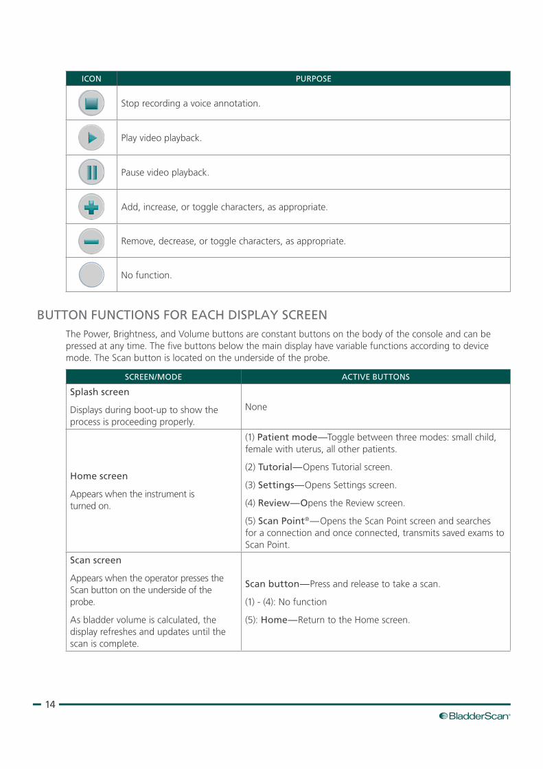
ICON PURPOSE
Stop recording a voice annotation.
Play video playback.
Pause video playback.
Add, increase, or toggle characters, as appropriate.
Remove, decrease, or toggle characters, as appropriate.
No function.
BUTTON FUNCTIONS FOR EACH DISPLAY SCREENThe Power, Brightness, and Volume buttons are constant buttons on the body of the console and can be pressed at any time. The five buttons below the main display have variable functions according to device mode. The Scan button is located on the underside of the probe.
SCREEN/MODE ACTIVE BUTTONS
Splash screen
Displays during boot‑up to show the process is proceeding properly.
None
Home screen
Appears when the instrument is turned on.
(1) Patient mode—Toggle between three modes: small child, female with uterus, all other patients.
(2) Tutorial—Opens Tutorial screen.
(3) Settings—Opens Settings screen.
(4) Review—Opens the Review screen.
(5) Scan Point®—Opens the Scan Point screen and searches for a connection and once connected, transmits saved exams to Scan Point.
Scan screen
Appears when the operator presses the Scan button on the underside of the probe.
As bladder volume is calculated, the display refreshes and updates until the scan is complete.
Scan button—Press and release to take a scan.
(1) ‑ (4): No function
(5): Home—Return to the Home screen.
15Operations & Maintenance Manual: Introduction
SCREEN/MODE ACTIVE BUTTONS
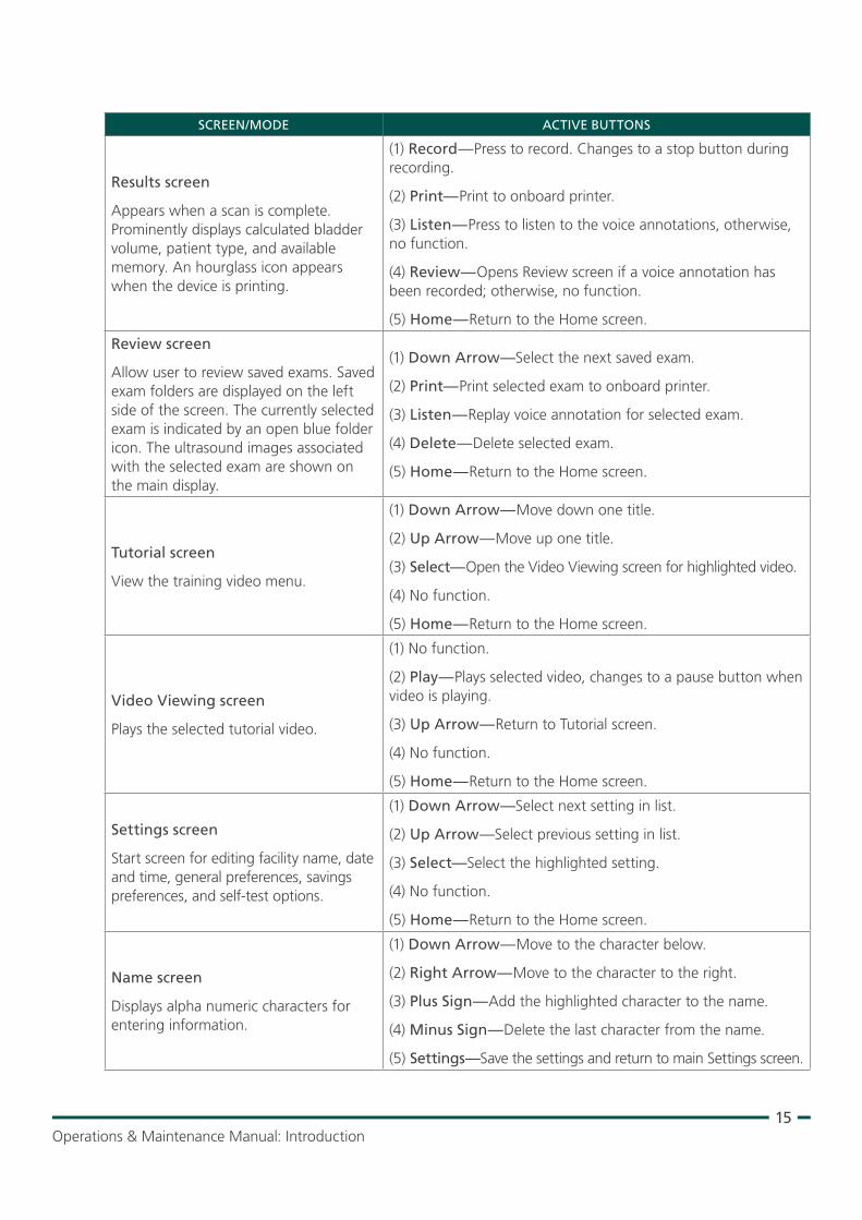
Results screen
Appears when a scan is complete. Prominently displays calculated bladder volume, patient type, and available memory. An hourglass icon appears when the device is printing.
(1) Record—Press to record. Changes to a stop button during recording.
(2) Print—Print to onboard printer.
(3) Listen—Press to listen to the voice annotations, otherwise, no function.
(4) Review—Opens Review screen if a voice annotation has been recorded; otherwise, no function.
(5) Home—Return to the Home screen.
Review screen
Allow user to review saved exams. Saved exam folders are displayed on the left side of the screen. The currently selected exam is indicated by an open blue folder icon. The ultrasound images associated with the selected exam are shown on the main display.
(1) Down Arrow—Select the next saved exam.
(2) Print—Print selected exam to onboard printer.
(3) Listen—Replay voice annotation for selected exam.
(4) Delete—Delete selected exam.
(5) Home—Return to the Home screen.
Tutorial screen
View the training video menu.
(1) Down Arrow—Move down one title.
(2) Up Arrow—Move up one title.
(3) Select—Open the Video Viewing screen for highlighted video.
(4) No function.
(5) Home—Return to the Home screen.
Video Viewing screen
Plays the selected tutorial video.
(1) No function.
(2) Play—Plays selected video, changes to a pause button when video is playing.
(3) Up Arrow—Return to Tutorial screen.
(4) No function.
(5) Home—Return to the Home screen.
Settings screen
Start screen for editing facility name, date and time, general preferences, savings preferences, and self‑test options.
(1) Down Arrow—Select next setting in list.
(2) Up Arrow—Select previous setting in list.
(3) Select—Select the highlighted setting.
(4) No function.
(5) Home—Return to the Home screen.
Name screen
Displays alpha numeric characters for entering information.
(1) Down Arrow—Move to the character below.
(2) Right Arrow—Move to the character to the right.
(3) Plus Sign—Add the highlighted character to the name.
(4) Minus Sign—Delete the last character from the name.
(5) Settings—Save the settings and return to main Settings screen.
16
SCREEN/MODE ACTIVE BUTTONS
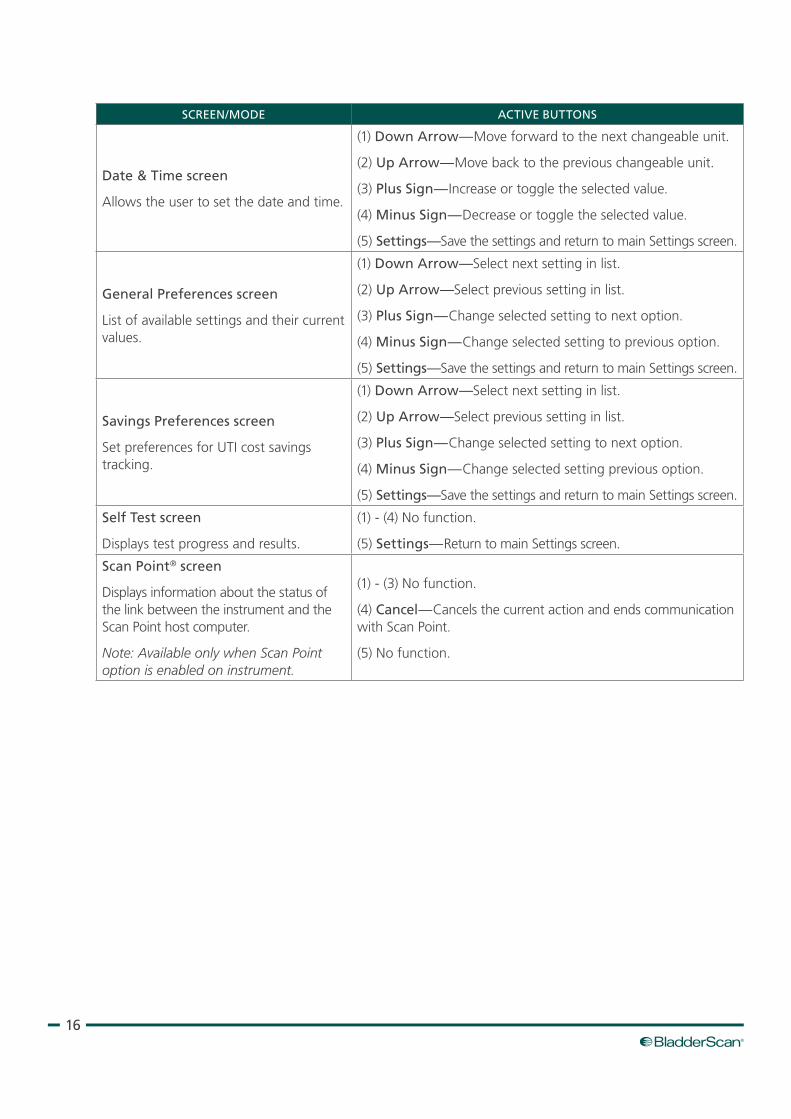
Date & Time screen
Allows the user to set the date and time.
(1) Down Arrow—Move forward to the next changeable unit.
(2) Up Arrow—Move back to the previous changeable unit.
(3) Plus Sign—Increase or toggle the selected value.
(4) Minus Sign—Decrease or toggle the selected value.
(5) Settings—Save the settings and return to main Settings screen.
General Preferences screen
List of available settings and their current values.
(1) Down Arrow—Select next setting in list.
(2) Up Arrow—Select previous setting in list.
(3) Plus Sign—Change selected setting to next option.
(4) Minus Sign—Change selected setting to previous option.
(5) Settings—Save the settings and return to main Settings screen.
Savings Preferences screen
Set preferences for UTI cost savings tracking.
(1) Down Arrow—Select next setting in list.
(2) Up Arrow—Select previous setting in list.
(3) Plus Sign—Change selected setting to next option.
(4) Minus Sign—Change selected setting previous option.
(5) Settings—Save the settings and return to main Settings screen.
Self Test screen
Displays test progress and results.
(1) ‑ (4) No function.
(5) Settings—Return to main Settings screen.
Scan Point® screen
Displays information about the status of the link between the instrument and the Scan Point host computer.
Note: Available only when Scan Point option is enabled on instrument.
(1) ‑ (3) No function.
(4) Cancel—Cancels the current action and ends communication with Scan Point.
(5) No function.
17Operations & Maintenance Manual: Introduction
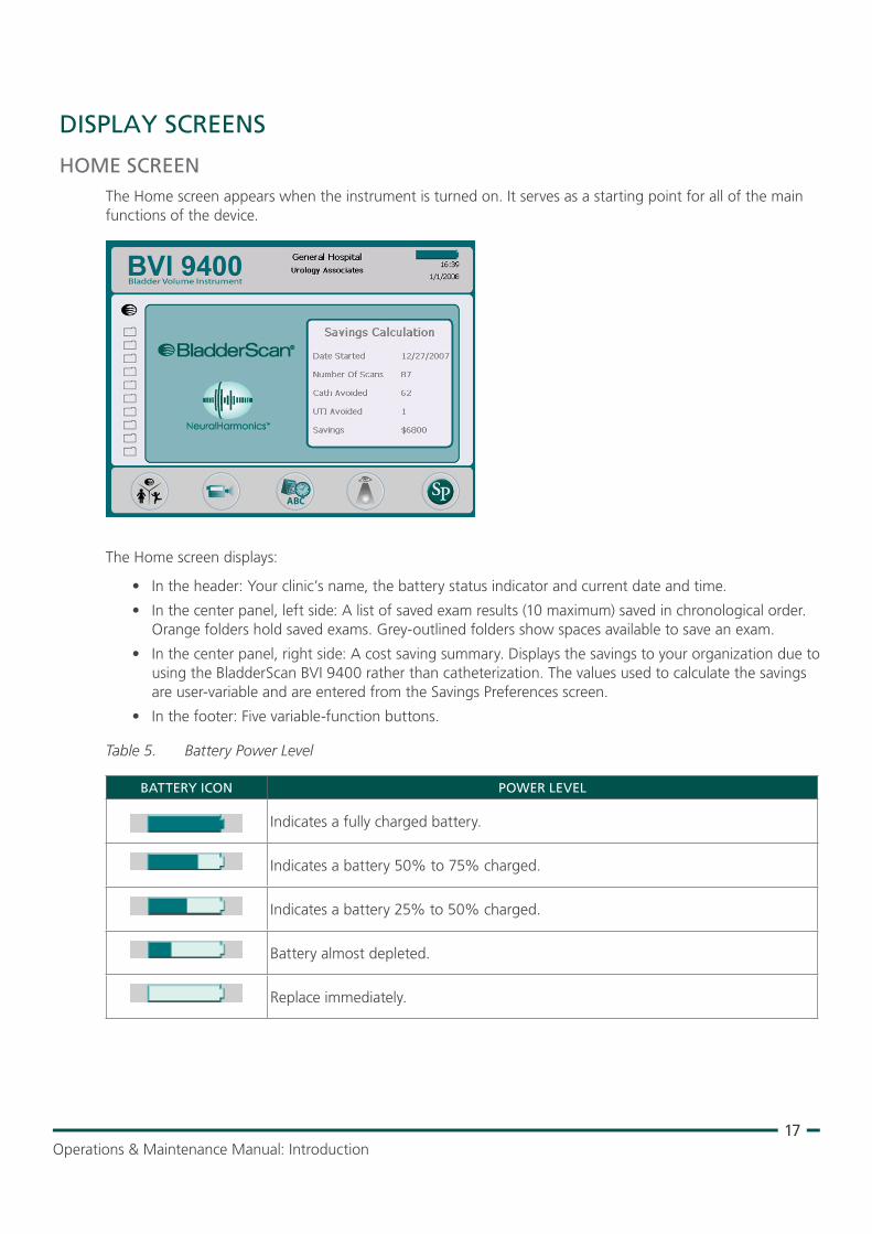
DISPLAY SCREENS
HOME SCREENThe Home screen appears when the instrument is turned on. It serves as a starting point for all of the main functions of the device.
The Home screen displays:
• In the header: Your clinic’s name, the battery status indicator and current date and time.
• In the center panel, left side: A list of saved exam results (10 maximum) saved in chronological order. Orange folders hold saved exams. Grey‑outlined folders show spaces available to save an exam.
• In the center panel, right side: A cost saving summary. Displays the savings to your organization due to using the BladderScan BVI 9400 rather than catheterization. The values used to calculate the savings are user‑variable and are entered from the Savings Preferences screen.
• In the footer: Five variable‑function buttons.
Table 5. Battery Power Level
BATTERY ICON POWER LEVEL
Indicates a fully charged battery.
Indicates a battery 50% to 75% charged.
Indicates a battery 25% to 50% charged.
Battery almost depleted.
Replace immediately.
18
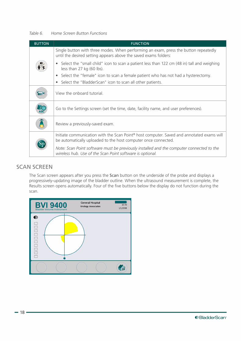
Table 6. Home Screen Button Functions
BUTTON FUNCTION
Single button with three modes. When performing an exam, press the button repeatedly until the desired setting appears above the saved exams folders:
• Select the “small child” icon to scan a patient less than 122 cm (48 in) tall and weighing less than 27 kg (60 lbs).
• Select the “female" icon to scan a female patient who has not had a hysterectomy.
• Select the “BladderScan" icon to scan all other patients.
View the onboard tutorial.
Go to the Settings screen (set the time, date, facility name, and user preferences).
Review a previously‑saved exam.
Initiate communication with the Scan Point® host computer. Saved and annotated exams will be automatically uploaded to the host computer once connected.
Note: Scan Point software must be previously installed and the computer connected to the wireless hub. Use of the Scan Point software is optional.
SCAN SCREENThe Scan screen appears after you press the Scan button on the underside of the probe and displays a progressively‑updating image of the bladder outline. When the ultrasound measurement is complete, the Results screen opens automatically. Four of the five buttons below the display do not function during the scan.
19Operations & Maintenance Manual: Introduction
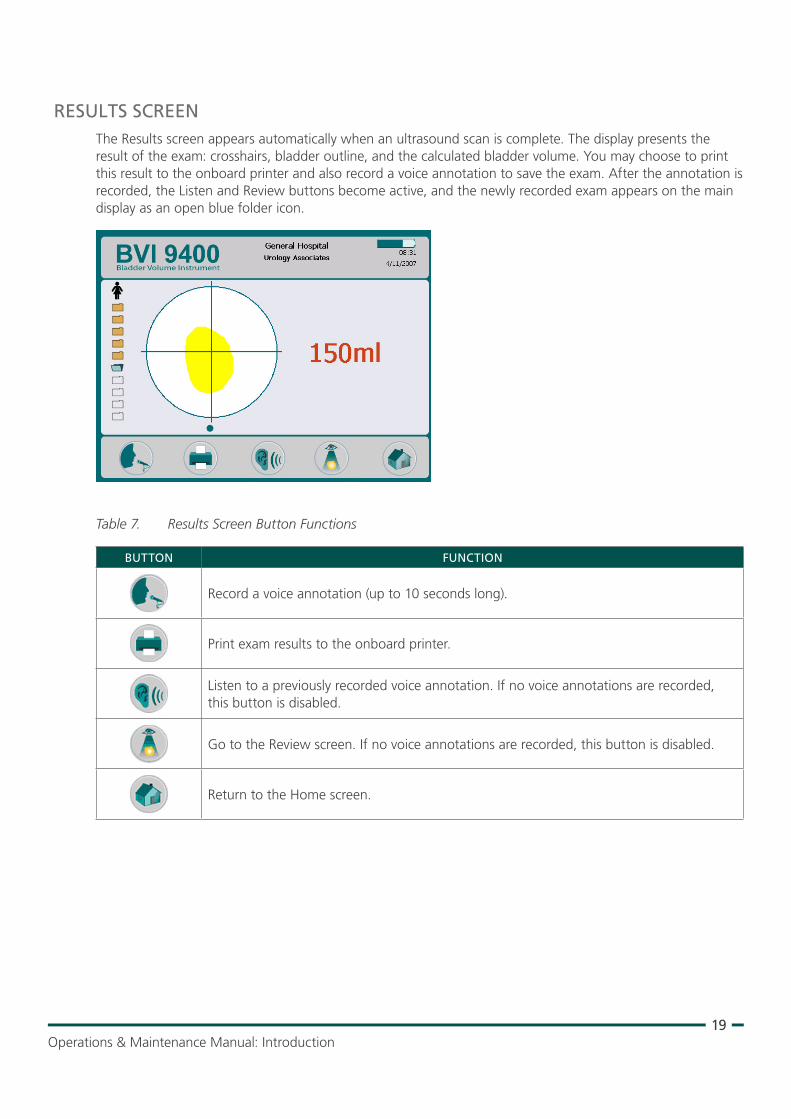
RESULTS SCREENThe Results screen appears automatically when an ultrasound scan is complete. The display presents the result of the exam: crosshairs, bladder outline, and the calculated bladder volume. You may choose to print this result to the onboard printer and also record a voice annotation to save the exam. After the annotation is recorded, the Listen and Review buttons become active, and the newly recorded exam appears on the main display as an open blue folder icon.
Table 7. Results Screen Button Functions
BUTTON FUNCTION
Record a voice annotation (up to 10 seconds long).
Print exam results to the onboard printer.
Listen to a previously recorded voice annotation. If no voice annotations are recorded, this button is disabled.
Go to the Review screen. If no voice annotations are recorded, this button is disabled.
Return to the Home screen.
20
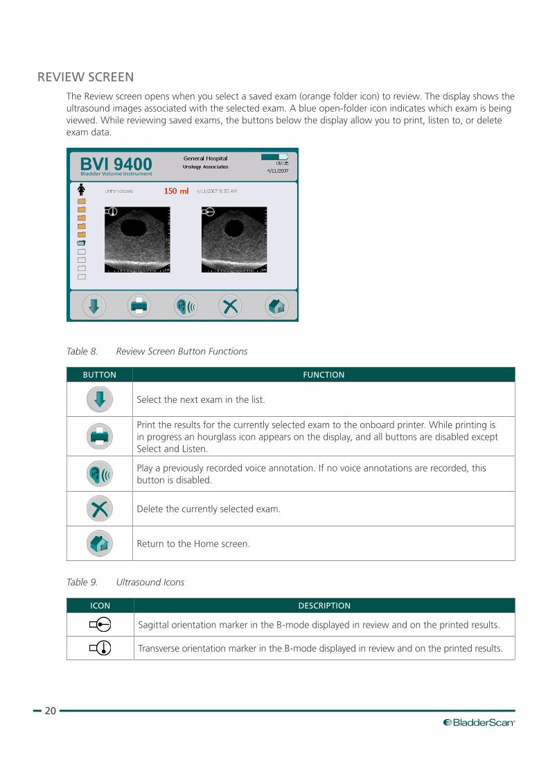
REVIEW SCREENThe Review screen opens when you select a saved exam (orange folder icon) to review. The display shows the ultrasound images associated with the selected exam. A blue open‑folder icon indicates which exam is being viewed. While reviewing saved exams, the buttons below the display allow you to print, listen to, or delete exam data.
Table 8. Review Screen Button Functions
BUTTON FUNCTION
Select the next exam in the list.
Print the results for the currently selected exam to the onboard printer. While printing is in progress an hourglass icon appears on the display, and all buttons are disabled except Select and Listen.
Play a previously recorded voice annotation. If no voice annotations are recorded, this button is disabled.
Delete the currently selected exam.
Return to the Home screen.
Table 9. Ultrasound Icons
ICON DESCRIPTION
Sagittal orientation marker in the B‑mode displayed in review and on the printed results.
Transverse orientation marker in the B‑mode displayed in review and on the printed results.
21Operations & Maintenance Manual: Introduction
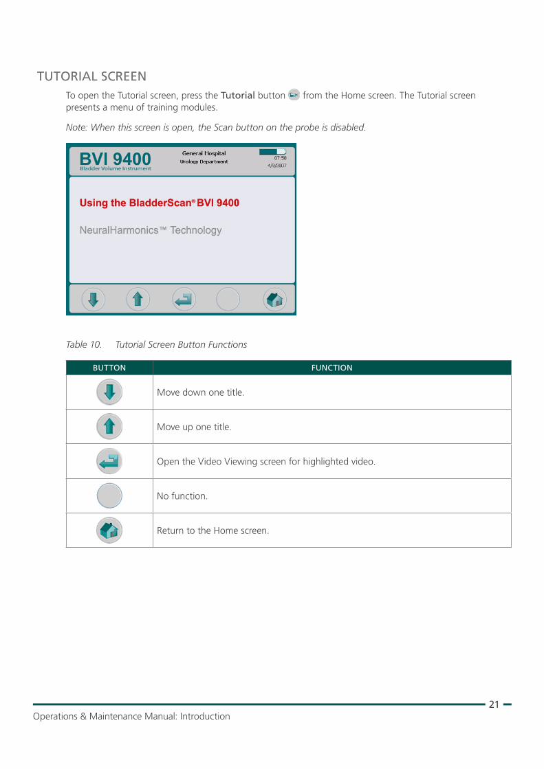
TUTORIAL SCREENTo open the Tutorial screen, press the Tutorial button from the Home screen. The Tutorial screen presents a menu of training modules.
Note: When this screen is open, the Scan button on the probe is disabled.
Table 10. Tutorial Screen Button Functions
BUTTON FUNCTION
Move down one title.
Move up one title.
Open the Video Viewing screen for highlighted video.
No function.
Return to the Home screen.
22
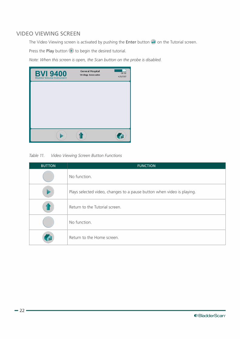
VIDEO VIEWING SCREENThe Video Viewing screen is activated by pushing the Enter button on the Tutorial screen.
Press the Play button to begin the desired tutorial.
Note: When this screen is open, the Scan button on the probe is disabled.
Table 11. Video Viewing Screen Button Functions
BUTTON FUNCTION
No function.
Plays selected video, changes to a pause button when video is playing.
Return to the Tutorial screen.
No function.
Return to the Home screen.
23Operations & Maintenance Manual: Introduction
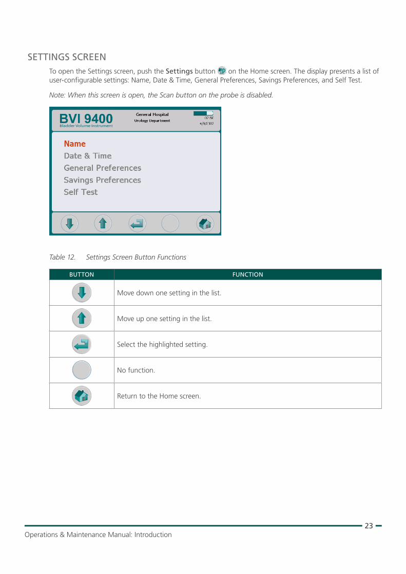
SETTINGS SCREENTo open the Settings screen, push the Settings button on the Home screen. The display presents a list of user‑configurable settings: Name, Date & Time, General Preferences, Savings Preferences, and Self Test.
Note: When this screen is open, the Scan button on the probe is disabled.
Table 12. Settings Screen Button Functions
BUTTON FUNCTION
Move down one setting in the list.
Move up one setting in the list.
Select the highlighted setting.
No function.
Return to the Home screen.
24
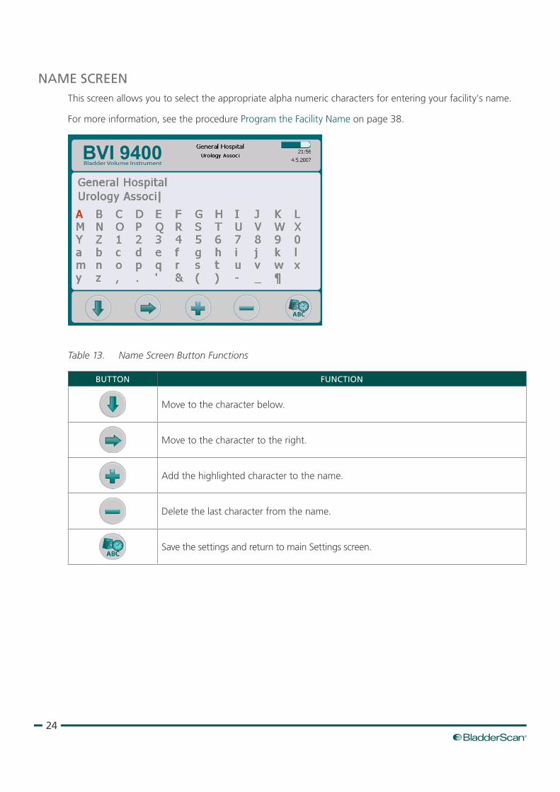
NAME SCREENThis screen allows you to select the appropriate alpha numeric characters for entering your facility's name.
For more information, see the procedure Program the Facility Name on page 38.
Table 13. Name Screen Button Functions
BUTTON FUNCTION
Move to the character below.
Move to the character to the right.
Add the highlighted character to the name.
Delete the last character from the name.
Save the settings and return to main Settings screen.
25Operations & Maintenance Manual: Introduction
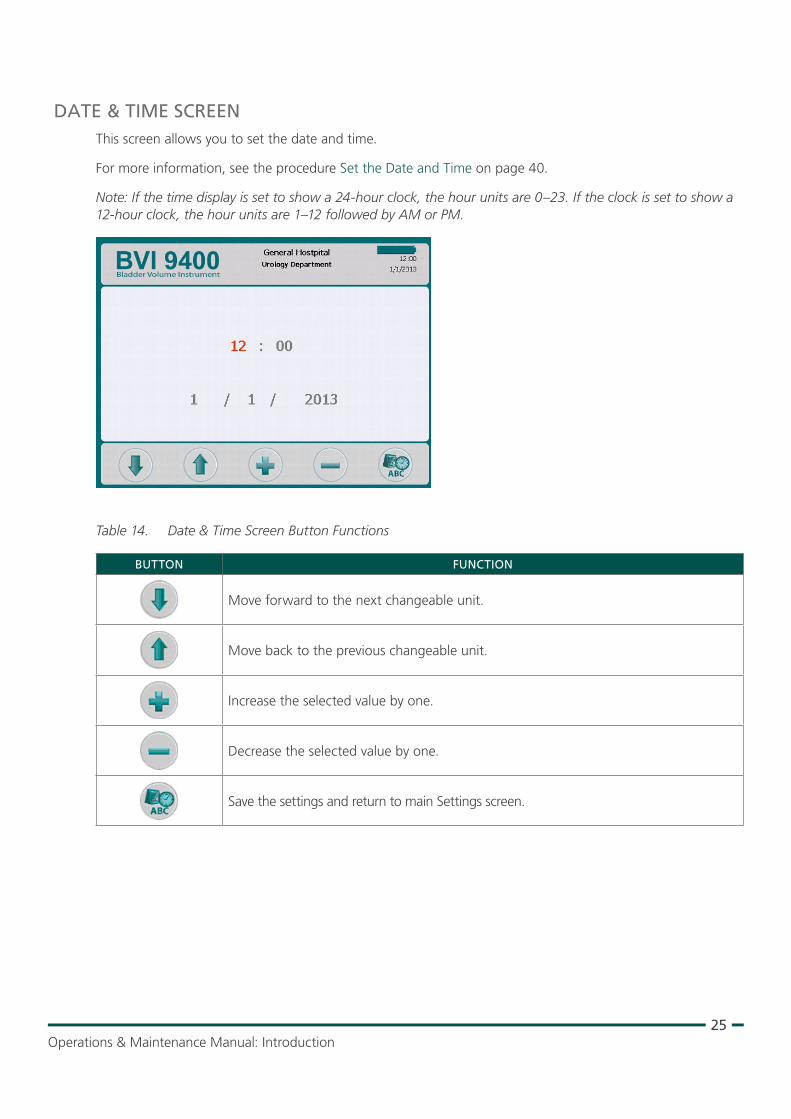
DATE & TIME SCREENThis screen allows you to set the date and time.
For more information, see the procedure Set the Date and Time on page 40.
Note: If the time display is set to show a 24‑hour clock, the hour units are 0–23. If the clock is set to show a 12‑hour clock, the hour units are 1–12 followed by AM or PM.
Table 14. Date & Time Screen Button Functions
BUTTON FUNCTION
Move forward to the next changeable unit.
Move back to the previous changeable unit.
Increase the selected value by one.
Decrease the selected value by one.
Save the settings and return to main Settings screen.
26
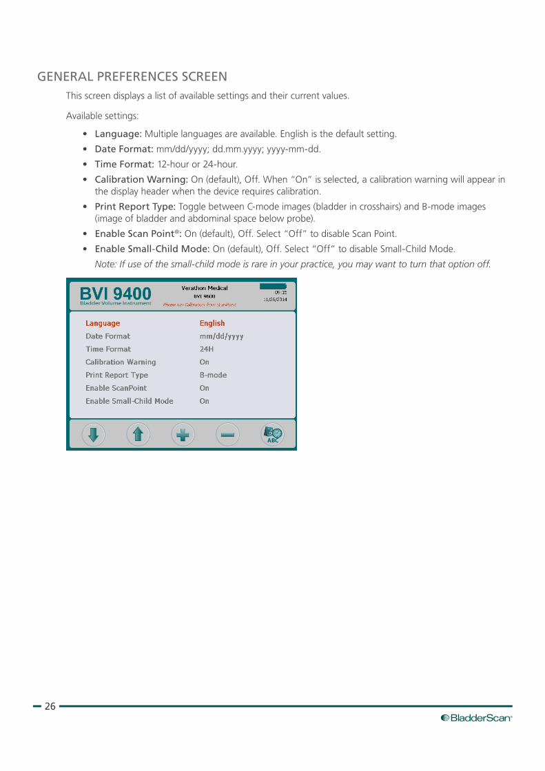
GENERAL PREFERENCES SCREENThis screen displays a list of available settings and their current values.
Available settings:
• Language: Multiple languages are available. English is the default setting.
• Date Format: mm/dd/yyyy; dd.mm.yyyy; yyyy‑mm‑dd.
• Time Format: 12‑hour or 24‑hour.
• Calibration Warning: On (default), Off. When “On” is selected, a calibration warning will appear in the display header when the device requires calibration.
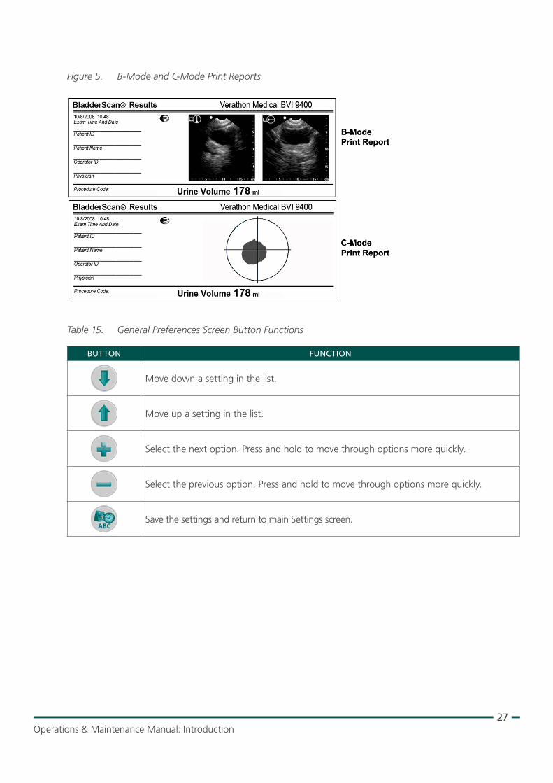
• Print Report Type: Toggle between C‑mode images (bladder in crosshairs) and B‑mode images (image of bladder and abdominal space below probe).
• Enable Scan Point®: On (default), Off. Select “Off” to disable Scan Point.
• Enable Small‑Child Mode: On (default), Off. Select “Off” to disable Small‑Child Mode.
Note: If use of the small‑child mode is rare in your practice, you may want to turn that option off.
27Operations & Maintenance Manual: Introduction
Figure 5. B‑Mode and C‑Mode Print Reports
Table 15. General Preferences Screen Button Functions
BUTTON FUNCTION
Move down a setting in the list.
Move up a setting in the list.
Select the next option. Press and hold to move through options more quickly.
Select the previous option. Press and hold to move through options more quickly.
Save the settings and return to main Settings screen.
28
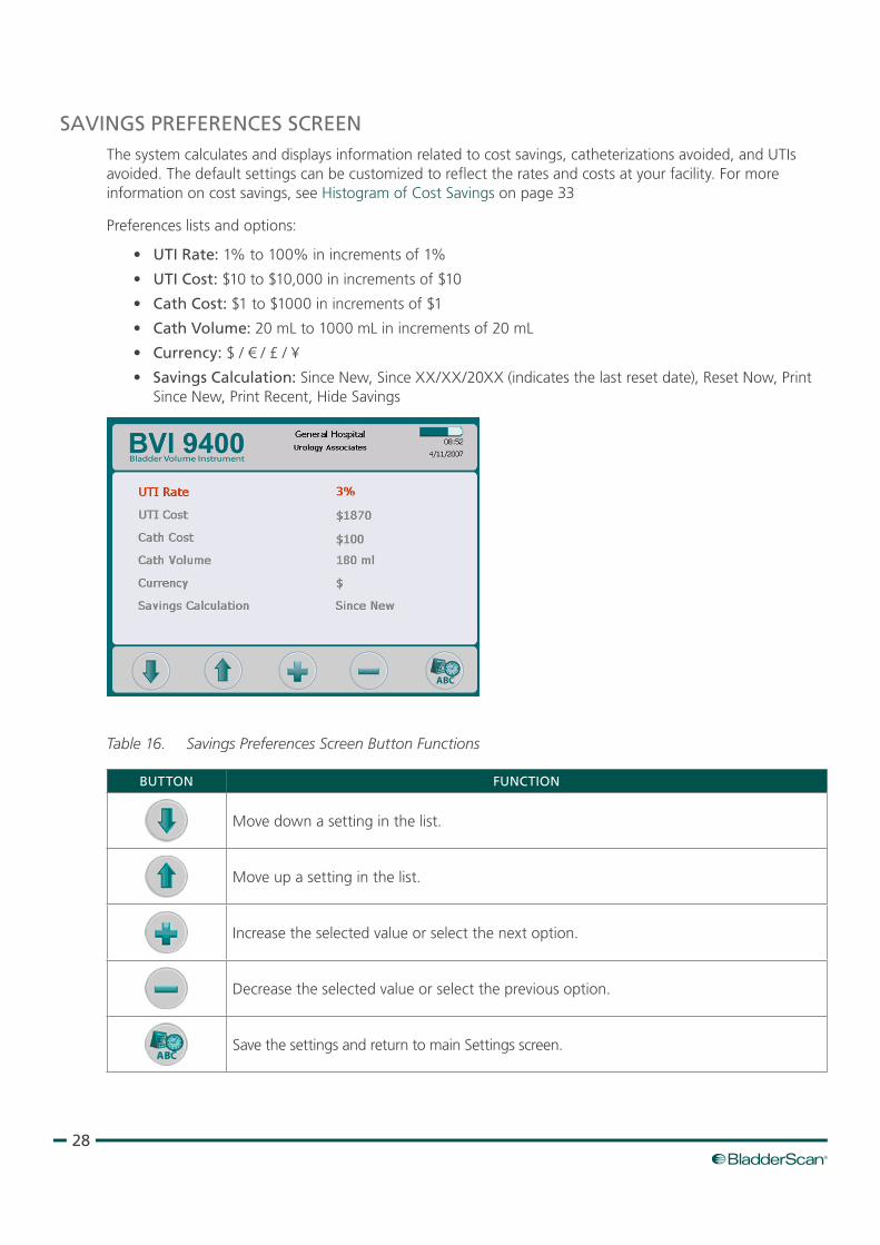
SAVINGS PREFERENCES SCREENThe system calculates and displays information related to cost savings, catheterizations avoided, and UTIs avoided. The default settings can be customized to reflect the rates and costs at your facility. For more information on cost savings, see Histogram of Cost Savings on page 33
Preferences lists and options:
• UTI Rate: 1% to 100% in increments of 1%
• UTI Cost: $10 to $10,000 in increments of $10
• Cath Cost: $1 to $1000 in increments of $1
• Cath Volume: 20 mL to 1000 mL in increments of 20 mL
• Currency: $ / € / £ / ¥
• Savings Calculation: Since New, Since XX/XX/20XX (indicates the last reset date), Reset Now, Print Since New, Print Recent, Hide Savings
Table 16. Savings Preferences Screen Button Functions
BUTTON FUNCTION
Move down a setting in the list.
Move up a setting in the list.
Increase the selected value or select the next option.
Decrease the selected value or select the previous option.
Save the settings and return to main Settings screen.
29Operations & Maintenance Manual: Introduction
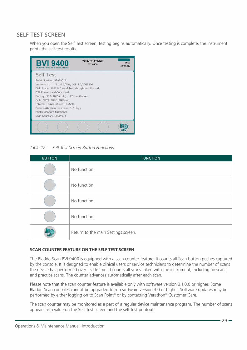
SELF TEST SCREENWhen you open the Self Test screen, testing begins automatically. Once testing is complete, the instrument prints the self‑test results.
Table 17. Self Test Screen Button Functions
BUTTON FUNCTION
No function.
No function.
No function.
No function.
Return to the main Settings screen.
SCAN COUNTER FEATURE ON THE SELF TEST SCREEN
The BladderScan BVI 9400 is equipped with a scan counter feature. It counts all Scan button pushes captured by the console. It is designed to enable clinical users or service technicians to determine the number of scans the device has performed over its lifetime. It counts all scans taken with the instrument, including air scans and practice scans. The counter advances automatically after each scan.
Please note that the scan counter feature is available only with software version 3.1.0.0 or higher. Some BladderScan consoles cannot be upgraded to run software version 3.0 or higher. Software updates may be performed by either logging on to Scan Point® or by contacting Verathon® Customer Care.
The scan counter may be monitored as a part of a regular device maintenance program. The number of scans appears as a value on the Self Test screen and the self‑test printout.
30
To ensure reliability, a backup copy of the scan count is stored in device memory. If both the scan counter and its backup copy are corrupted, the scan counter will automatically reset to a zero value.
The scan counter feature is designed so that the value cannot be manually reset or modified by the clinical user or service partner.
VIEWING THE SCAN COUNTER
The scan counter can be viewed on the Self Test screen.
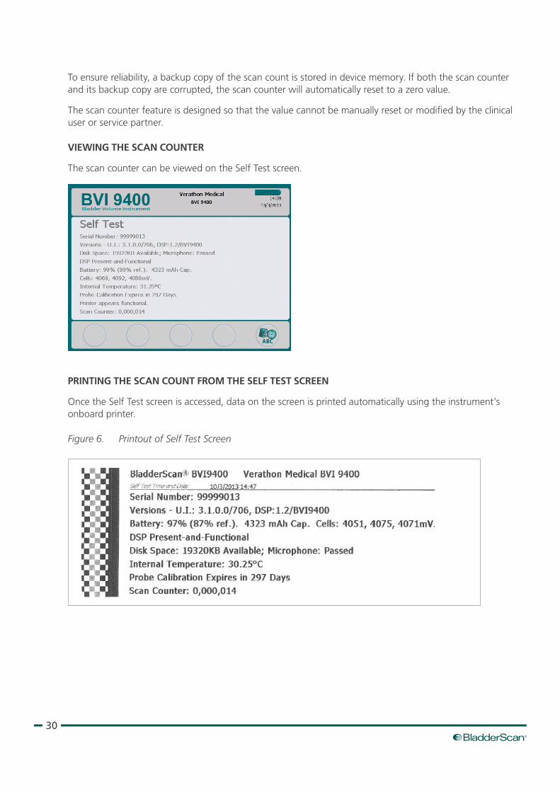
PRINTING THE SCAN COUNT FROM THE SELF TEST SCREEN
Once the Self Test screen is accessed, data on the screen is printed automatically using the instrument’s onboard printer.
Figure 6. Printout of Self Test Screen
31Operations & Maintenance Manual: Introduction
TROUBLESHOOTING
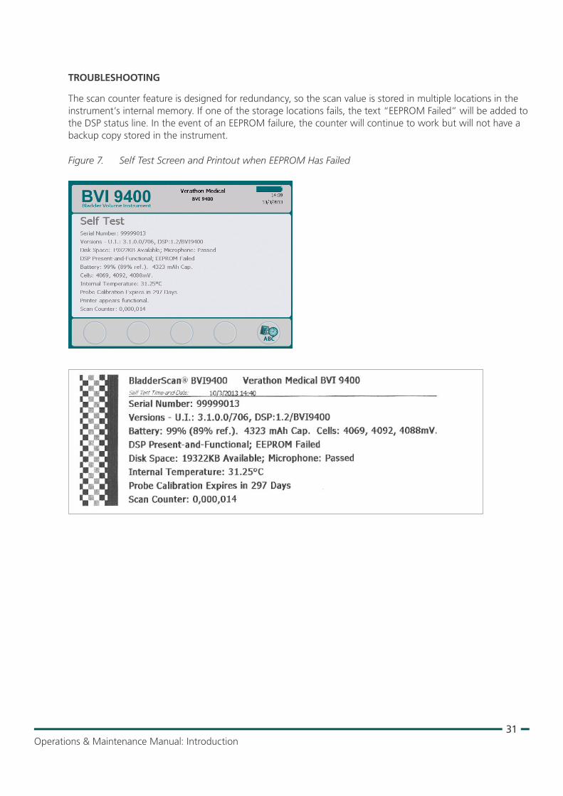
The scan counter feature is designed for redundancy, so the scan value is stored in multiple locations in the instrument’s internal memory. If one of the storage locations fails, the text “EEPROM Failed” will be added to the DSP status line. In the event of an EEPROM failure, the counter will continue to work but will not have a backup copy stored in the instrument.
Figure 7. Self Test Screen and Printout when EEPROM Has Failed
32
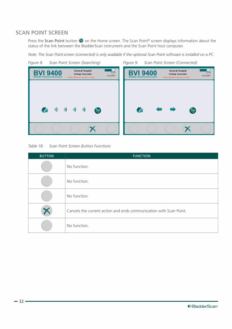
SCAN POINT SCREENPress the Scan Point button on the Home screen. The Scan Point® screen displays information about the status of the link between the BladderScan instrument and the Scan Point host computer.
Note: The Scan Point screen (connected) is only available if the optional Scan Point software is installed on a PC.
Figure 8. Scan Point Screen (Searching) Figure 9. Scan Point Screen (Connected)
Table 18. Scan Point Screen Button Functions
BUTTON FUNCTION
No function.
No function.
No function.
Cancels the current action and ends communication with Scan Point.
No function.
33Operations & Maintenance Manual: Introduction
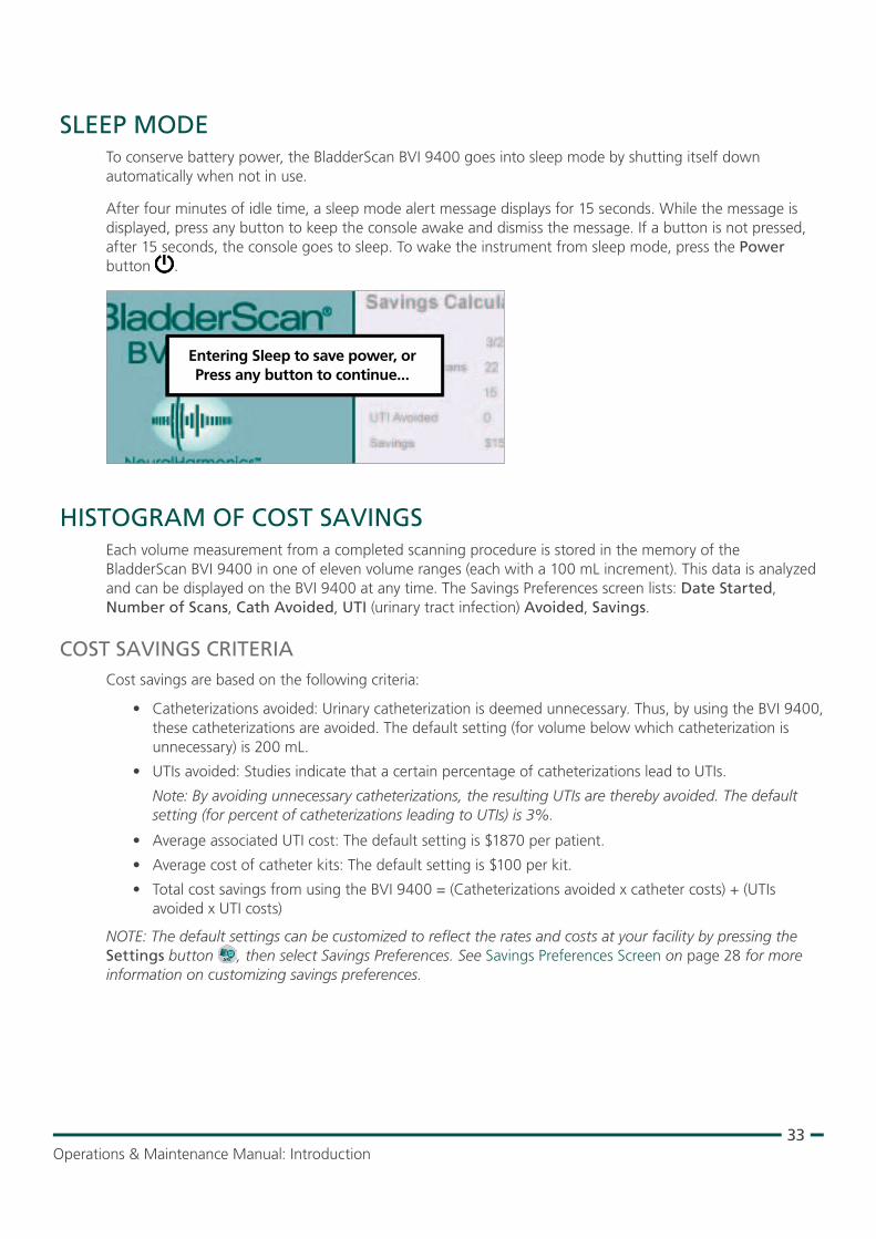
SLEEP MODETo conserve battery power, the BladderScan BVI 9400 goes into sleep mode by shutting itself down automatically when not in use.
After four minutes of idle time, a sleep mode alert message displays for 15 seconds. While the message is displayed, press any button to keep the console awake and dismiss the message. If a button is not pressed, after 15 seconds, the console goes to sleep. To wake the instrument from sleep mode, press the Power button .
Entering Sleep to save power, orPress any button to continue...
HISTOGRAM OF COST SAVINGSEach volume measurement from a completed scanning procedure is stored in the memory of the BladderScan BVI 9400 in one of eleven volume ranges (each with a 100 mL increment). This data is analyzed and can be displayed on the BVI 9400 at any time. The Savings Preferences screen lists: Date Started, Number of Scans, Cath Avoided, UTI (urinary tract infection) Avoided, Savings.
COST SAVINGS CRITERIACost savings are based on the following criteria:
• Catheterizations avoided: Urinary catheterization is deemed unnecessary. Thus, by using the BVI 9400, these catheterizations are avoided. The default setting (for volume below which catheterization is unnecessary) is 200 mL.
• UTIs avoided: Studies indicate that a certain percentage of catheterizations lead to UTIs.
Note: By avoiding unnecessary catheterizations, the resulting UTIs are thereby avoided. The default setting (for percent of catheterizations leading to UTIs) is 3%.
• Average associated UTI cost: The default setting is $1870 per patient.
• Average cost of catheter kits: The default setting is $100 per kit.
• Total cost savings from using the BVI 9400 = (Catheterizations avoided x catheter costs) + (UTIs avoided x UTI costs)
NOTE: The default settings can be customized to reflect the rates and costs at your facility by pressing the Settings button , then select Savings Preferences. See Savings Preferences Screen on page 28 for more information on customizing savings preferences.
34
SETTING UP
To help you get up and running as quickly as possible, the next few pages explain how to:
1. Perform the Initial Inspection
2. Set Up the Battery
3. Attach the Probe to the Console
4. Program the Facility Name
5. Set the Date and Time
6. Load the Thermal Paper
7. Attach the Instrument to a Medical Cart (Optional)
8. Install Scan Point with QuickPrint (Optional)
9. Watch the Onboard Tutorial
PROCEdURE 1. PERFORM THE INITIAL INSPECTION
When you receive the system, Verathon® recommends that an operator familiar with the instrument perform a full visual inspection of the system for any obvious physical damage that may have occurred during shipment.
1. Carefully open the top of the shipping box. Do not insert anything sharp through the box.
2. Remove the contents and verify that you have received the appropriate components for your system.
3. Inspect the components for damage.
4. If any of the components are missing or damaged, notify the carrier and Verathon Customer Care or your local representative.
35Operations & Maintenance Manual: Setting Up
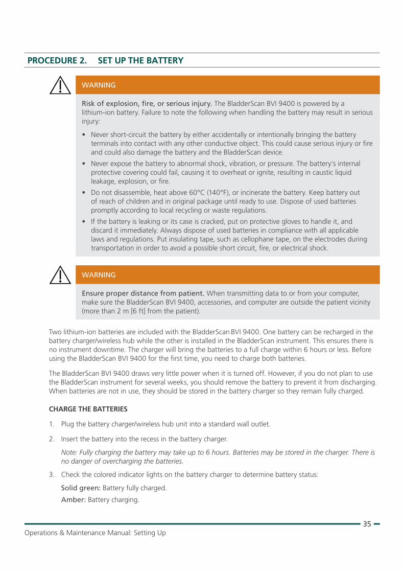
PROCEdURE 2. SET UP THE BATTERY
Risk of explosion, fire, or serious injury. The BladderScan BVI 9400 is powered by a lithium‑ion battery. Failure to note the following when handling the battery may result in serious injury:
• Never short‑circuit the battery by either accidentally or intentionally bringing the battery terminals into contact with any other conductive object. This could cause serious injury or fire and could also damage the battery and the BladderScan device.
• Never expose the battery to abnormal shock, vibration, or pressure. The battery’s internal protective covering could fail, causing it to overheat or ignite, resulting in caustic liquid leakage, explosion, or fire.
• Do not disassemble, heat above 60°C (140°F), or incinerate the battery. Keep battery out of reach of children and in original package until ready to use. Dispose of used batteries promptly according to local recycling or waste regulations.
• If the battery is leaking or its case is cracked, put on protective gloves to handle it, and discard it immediately. Always dispose of used batteries in compliance with all applicable laws and regulations. Put insulating tape, such as cellophane tape, on the electrodes during transportation in order to avoid a possible short circuit, fire, or electrical shock.
WARNING
Ensure proper distance from patient. When transmitting data to or from your computer, make sure the BladderScan BVI 9400, accessories, and computer are outside the patient vicinity (more than 2 m [6 ft] from the patient).
WARNING
Two lithium‑ion batteries are included with the BladderScan BVI 9400. One battery can be recharged in the battery charger/wireless hub while the other is installed in the BladderScan instrument. This ensures there is no instrument downtime. The charger will bring the batteries to a full charge within 6 hours or less. Before using the BladderScan BVI 9400 for the first time, you need to charge both batteries.
The BladderScan BVI 9400 draws very little power when it is turned off. However, if you do not plan to use the BladderScan instrument for several weeks, you should remove the battery to prevent it from discharging. When batteries are not in use, they should be stored in the battery charger so they remain fully charged.
CHARGE THE BATTERIES
1. Plug the battery charger/wireless hub unit into a standard wall outlet.
2. Insert the battery into the recess in the battery charger.
Note: Fully charging the battery may take up to 6 hours. Batteries may be stored in the charger. There is no danger of overcharging the batteries.
3. Check the colored indicator lights on the battery charger to determine battery status:
Solid green: Battery fully charged.
Amber: Battery charging.
36
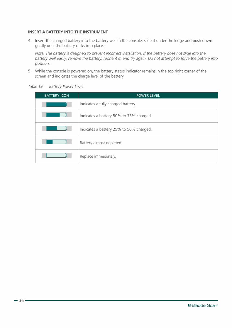
INSERT A BATTERY INTO THE INSTRUMENT
4. Insert the charged battery into the battery well in the console, slide it under the ledge and push down gently until the battery clicks into place.
Note: The battery is designed to prevent incorrect installation. If the battery does not slide into the battery well easily, remove the battery, reorient it, and try again. Do not attempt to force the battery into position.
5. While the console is powered on, the battery status indicator remains in the top right corner of the screen and indicates the charge level of the battery.
Table 19. Battery Power Level
BATTERY ICON POWER LEVEL
Indicates a fully charged battery.
Indicates a battery 50% to 75% charged.
Indicates a battery 25% to 50% charged.
Battery almost depleted.
Replace immediately.
37Operations & Maintenance Manual: Setting Up
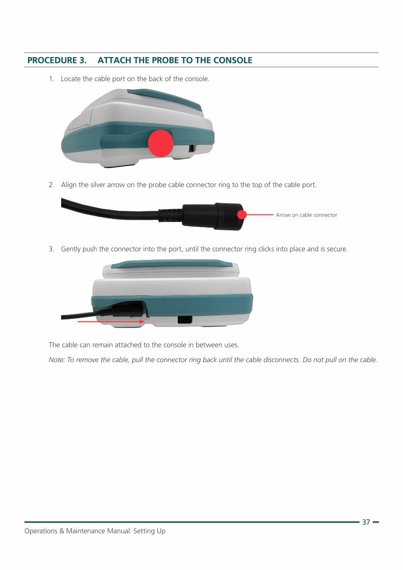
PROCEdURE 3. ATTACH THE PROBE TO THE CONSOLE
1. Locate the cable port on the back of the console.
2. Align the silver arrow on the probe cable connector ring to the top of the cable port.
Arrow on cable connector
3. Gently push the connector into the port, until the connector ring clicks into place and is secure.
The cable can remain attached to the console in between uses.
Note: To remove the cable, pull the connector ring back until the cable disconnects. Do not pull on the cable.
38
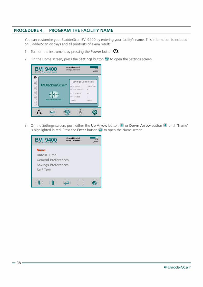
PROCEdURE 4. PROGRAM THE FACILITY NAME
You can customize your BladderScan BVI 9400 by entering your facility’s name. This information is included on BladderScan displays and all printouts of exam results.
1. Turn on the instrument by pressing the Power button .
2. On the Home screen, press the Settings button to open the Settings screen.
3. On the Settings screen, push either the Up Arrow button or Down Arrow button until “Name” is highlighted in red. Press the Enter button to open the Name screen.
39Operations & Maintenance Manual: Setting Up
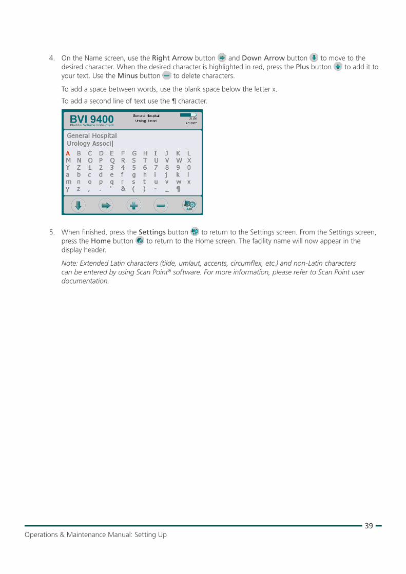
4. On the Name screen, use the Right Arrow button and Down Arrow button to move to the desired character. When the desired character is highlighted in red, press the Plus button to add it to your text. Use the Minus button to delete characters.
To add a space between words, use the blank space below the letter x.
To add a second line of text use the ¶ character.
5. When finished, press the Settings button to return to the Settings screen. From the Settings screen, press the Home button to return to the Home screen. The facility name will now appear in the display header.
Note: Extended Latin characters (tilde, umlaut, accents, circumflex, etc.) and non‑Latin characters can be entered by using Scan Point® software. For more information, please refer to Scan Point user documentation.
40
PROCEdURE 5. SET THE dATE ANd TIME
1. Turn on the instrument by pressing the Power button .
2. From the Home screen, press the Settings button to open the Settings screen.
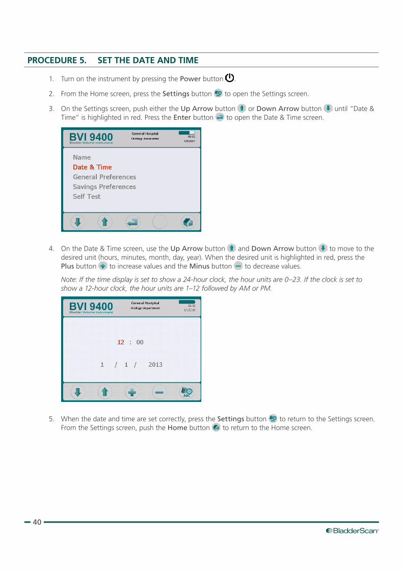
3. On the Settings screen, push either the Up Arrow button or Down Arrow button until “Date & Time“ is highlighted in red. Press the Enter button to open the Date & Time screen.
4. On the Date & Time screen, use the Up Arrow button and Down Arrow button to move to the desired unit (hours, minutes, month, day, year). When the desired unit is highlighted in red, press the Plus button to increase values and the Minus button to decrease values.
Note: If the time display is set to show a 24‑hour clock, the hour units are 0–23. If the clock is set to show a 12‑hour clock, the hour units are 1–12 followed by AM or PM.
5. When the date and time are set correctly, press the Settings button to return to the Settings screen. From the Settings screen, push the Home button to return to the Home screen.
41Operations & Maintenance Manual: Setting Up
PROCEdURE 6. LOAd THE THERMAL PAPER
If paper appears to be stuck in the printer, see the procedure Clear a Paper Jam on page 64.
1. Locate the paper compartment door on the base of the console, behind the display.
2. Slide the door out, then lift up.
3. If there is an empty paper roll, remove it.
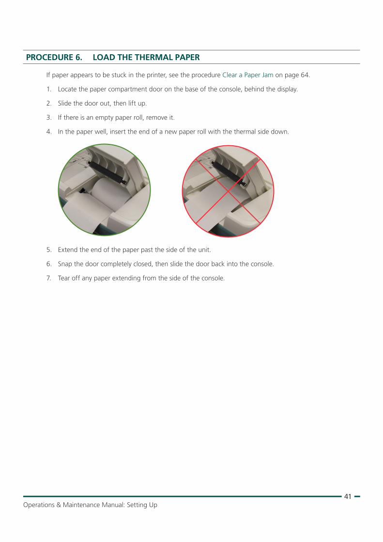
4. In the paper well, insert the end of a new paper roll with the thermal side down.
5. Extend the end of the paper past the side of the unit.
6. Snap the door completely closed, then slide the door back into the console.
7. Tear off any paper extending from the side of the console.
42
PROCEdURE 7. ATTACH THE INSTRUMENT TO A MEdICAL CART (OPTIONAL)
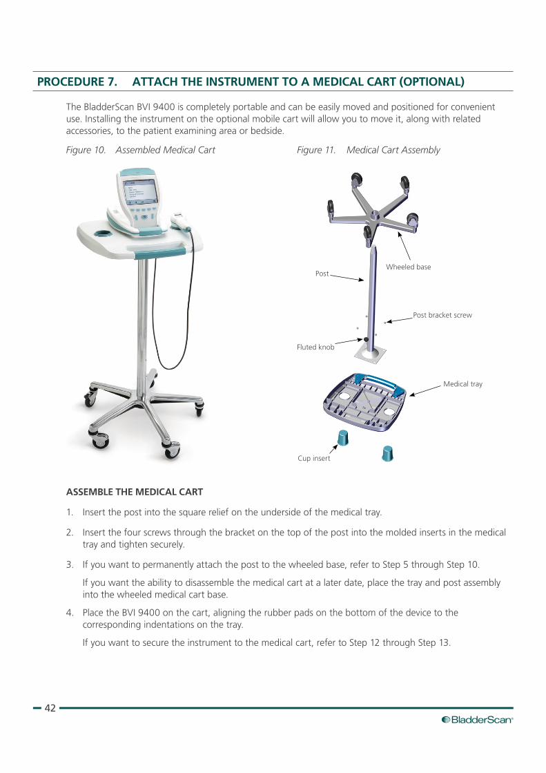
The BladderScan BVI 9400 is completely portable and can be easily moved and positioned for convenient use. Installing the instrument on the optional mobile cart will allow you to move it, along with related accessories, to the patient examining area or bedside.
Figure 10. Assembled Medical Cart Figure 11. Medical Cart Assembly
Medical tray
Fluted knob
Post bracket screw
Cup insert
PostWheeled base
ASSEMBLE THE MEdICAL CART
1. Insert the post into the square relief on the underside of the medical tray.
2. Insert the four screws through the bracket on the top of the post into the molded inserts in the medical tray and tighten securely.
3. If you want to permanently attach the post to the wheeled base, refer to Step 5 through Step 10.
If you want the ability to disassemble the medical cart at a later date, place the tray and post assembly into the wheeled medical cart base.
4. Place the BVI 9400 on the cart, aligning the rubber pads on the bottom of the device to the corresponding indentations on the tray.
If you want to secure the instrument to the medical cart, refer to Step 12 through Step 13.
43Operations & Maintenance Manual: Setting Up
PERMANENTLY ATTACH THE POST TO THE WHEELEd BASE (OPTIONAL)
5. Place the wheeled cart base on a level floor.
6. Open the two tubes of Loctite® 680 supplied with the cart by snapping off the tips of the tubes.
7. Apply the Loctite 680 all around the tapered portion of the post. Use all of the contents of both tubes. Complete coverage around the tapered portion is not necessary as the Loctite will spread upon insertion into the base.
8. Slide the post into the hole in the base with a twisting motion and press down firmly.
9. Wipe off any excess Loctite with a paper towel, and then discard the towel.
10. Allow the post and base to sit undisturbed for 3 hours.
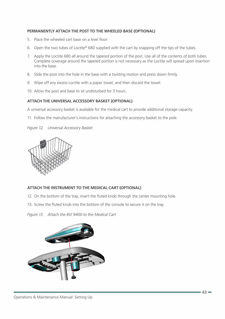
ATTACH THE UNIVERSAL ACCESSORY BASKET (OPTIONAL)
A universal accessory basket is available for the medical cart to provide additional storage capacity.
11. Follow the manufacturer’s instructions for attaching the accessory basket to the pole.
Figure 12. Universal Accessory Basket
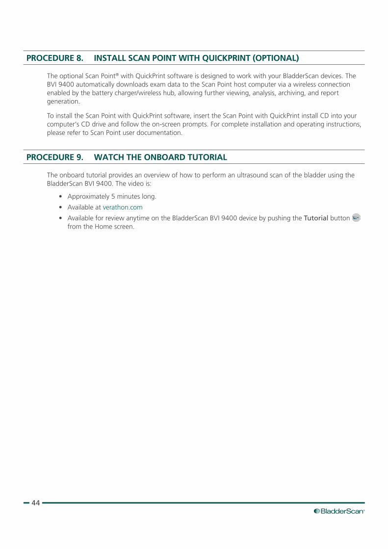
ATTACH THE INSTRUMENT TO THE MEdICAL CART (OPTIONAL)
12. On the bottom of the tray, insert the fluted knob through the center mounting hole.
13. Screw the fluted knob into the bottom of the console to secure it on the tray.
Figure 13. Attach the BVI 9400 to the Medical Cart
44
PROCEdURE 8. INSTALL SCAN POINT WITH QUICKPRINT (OPTIONAL)
The optional Scan Point® with QuickPrint software is designed to work with your BladderScan devices. The BVI 9400 automatically downloads exam data to the Scan Point host computer via a wireless connection enabled by the battery charger/wireless hub, allowing further viewing, analysis, archiving, and report generation.
To install the Scan Point with QuickPrint software, insert the Scan Point with QuickPrint install CD into your computer’s CD drive and follow the on‑screen prompts. For complete installation and operating instructions, please refer to Scan Point user documentation.
PROCEdURE 9. WATCH THE ONBOARd TUTORIAL
The onboard tutorial provides an overview of how to perform an ultrasound scan of the bladder using the BladderScan BVI 9400. The video is:
• Approximately 5 minutes long.
• Available at verathon.com
• Available for review anytime on the BladderScan BVI 9400 device by pushing the Tutorial button from the Home screen.
45Operations & Maintenance Manual: Using the Device
USING THE DEVICE
Risk of explosion. If you use the BladderScan BVI 9400 in the presence of flammable anesthetics, the hazard of potential explosion exists.
WARNING
Potential patient hazard. To date, exposure to low‑power, pulsed diagnostic ultrasound has not been shown to produce adverse effects. However, medical professionals should use ultrasound only when clinically indicated, using the lowest exposure times possible to obtain accurate measurements. The ultrasonic output of the BladderScan BVI 9400 is not user adjustable and is limited to the minimum level necessary for effective performance. For more information about the acoustic output levels of this device, see the chapter Product Specifications on page 65.
WARNING
Risk of patient injury and inaccurate measurements/results. When using the instrument, be aware of the following conditions that can affect ultrasound transmission and decrease the accuracy of exam results.
• Use care when scanning patients who have had suprapubic or pelvic surgery. Scar tissue, surgical incisions, sutures, and staples can affect ultrasound transmission and accuracy.
• A catheter in the patient’s bladder may affect the accuracy of the bladder volume measurement in two ways: 1) by introducing air into the bladder that may block the ultrasound signal, and 2) by having the catheter‑retaining balloon interfere with the volume measurement. However, the volume measurement may still be clinically useful if it is large (detecting a blocked catheter, for example).
• Obesity may affect bladder volume measurements. Lift as much abdominal adipose tissue out of the way of the instrument as possible. Apply more pressure to the probe to reduce the amount of adipose tissue through which the ultrasound must pass.
Accuracy is compromised if the user does not obtain an optimal, repeatable image.
WARNING
Do not use the BladderScan BVI 9400 on:
• A patient who has open skin or wounds in the suprapubic area.
• A patient with ascites.
• A pregnant patient.
WARNING
46
PROCEdURE 1. PREPARE FOR THE EXAM
1. Ensure you are familiar with the parts and functions of the BladderScan instrument. For more information, see the Introduction chapter on page 7.
2. If you are a new BladderScan instrument user, Verathon® recommends you perform your first exam on a patient with a moderately full bladder rather than initially attempting to locate and scan a nearly empty bladder.
3. Check the instrument’s battery icon to ensure the battery has sufficient power.
If the battery icon shows ¼ or less full, replace the battery with a fully charged battery before proceeding. Place the discharged battery in the battery charger.
4. Ensure that the instrument has been properly cleaned according to the instructions in the chapter Cleaning & Maintenance on page 52.
5. Be aware of the following conditions that may affect ultrasound transmission and the accuracy of the exam:
• A catheter in the patient’s bladder. The presence of a catheter may affect the accuracy of the bladder volume measurement, but the measurement may still be clinically useful (detecting a blocked catheter, for example).
• Previous suprapubic or pelvic surgery. Scar tissue, surgical incisions, sutures, and staples can affect ultrasound transmission and reflection.
Do not use the BVI 9400 on:
• Patients with ascites.
• Patients with open skin or wounds in the suprapubic region.
• Pregnant patients.
47Operations & Maintenance Manual: Using the Device
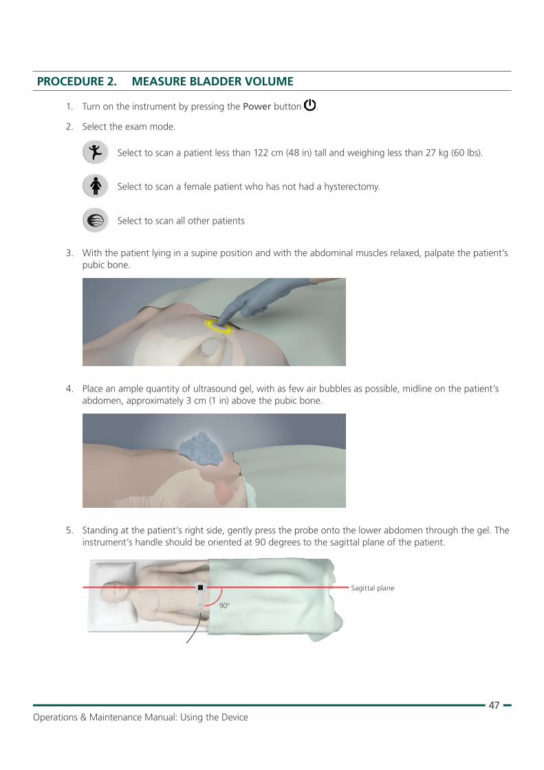
PROCEdURE 2. MEASURE BLAddER VOLUME
1. Turn on the instrument by pressing the Power button .
2. Select the exam mode.
Select to scan a patient less than 122 cm (48 in) tall and weighing less than 27 kg (60 lbs).
Select to scan a female patient who has not had a hysterectomy.
Select to scan all other patients
3. With the patient lying in a supine position and with the abdominal muscles relaxed, palpate the patient’s pubic bone.
4. Place an ample quantity of ultrasound gel, with as few air bubbles as possible, midline on the patient’s abdomen, approximately 3 cm (1 in) above the pubic bone.
5. Standing at the patient’s right side, gently press the probe onto the lower abdomen through the gel. The instrument’s handle should be oriented at 90 degrees to the sagittal plane of the patient.
Sagittal plane
90o
48
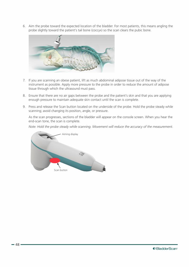
6. Aim the probe toward the expected location of the bladder. For most patients, this means angling the probe slightly toward the patient’s tail bone (coccyx) so the scan clears the pubic bone.
7. If you are scanning an obese patient, lift as much abdominal adipose tissue out of the way of the instrument as possible. Apply more pressure to the probe in order to reduce the amount of adipose tissue through which the ultrasound must pass.
8. Ensure that there are no air gaps between the probe and the patient’s skin and that you are applying enough pressure to maintain adequate skin contact until the scan is complete.
9. Press and release the Scan button located on the underside of the probe. Hold the probe steady while scanning; avoid changing its position, angle, or pressure.
As the scan progresses, sections of the bladder will appear on the console screen. When you hear the end‑scan tone, the scan is complete.
Note: Hold the probe steady while scanning. Movement will reduce the accuracy of the measurement.
Scan button
Aiming display
49Operations & Maintenance Manual: Using the Device
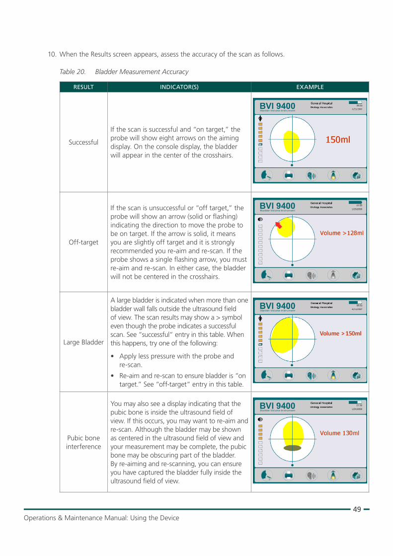
10. When the Results screen appears, assess the accuracy of the scan as follows.
Table 20. Bladder Measurement Accuracy
RESULT INDICATOR(S) EXAMPLE
Successful
If the scan is successful and “on target,” the probe will show eight arrows on the aiming display. On the console display, the bladder will appear in the center of the crosshairs.
Off‑target
If the scan is unsuccessful or “off target,” the probe will show an arrow (solid or flashing) indicating the direction to move the probe to be on target. If the arrow is solid, it means you are slightly off target and it is strongly recommended you re‑aim and re‑scan. If the probe shows a single flashing arrow, you must re‑aim and re‑scan. In either case, the bladder will not be centered in the crosshairs.
Large Bladder
A large bladder is indicated when more than one bladder wall falls outside the ultrasound field of view. The scan results may show a > symbol even though the probe indicates a successful scan. See “successful“ entry in this table. When this happens, try one of the following:
• Apply less pressure with the probe and re‑scan.
• Re‑aim and re‑scan to ensure bladder is “on target.” See “off‑target“ entry in this table.
Pubic bone interference
You may also see a display indicating that the pubic bone is inside the ultrasound field of view. If this occurs, you may want to re‑aim and re‑scan. Although the bladder may be shown as centered in the ultrasound field of view and your measurement may be complete, the pubic bone may be obscuring part of the bladder. By re‑aiming and re‑scanning, you can ensure you have captured the bladder fully inside the ultrasound field of view.
50
11. If necessary, use the following orientation in order to re‑aim the probe, and then re‑scan the patient:
• The small dot at the base of the crosshairs represents the feet of the patient.
• The top of the crosshairs represents the patient’s head.
• The upper left quadrant represents the patient’s right shoulder.
12. If you would like to save the exam data, continue to the next procedure.
PROCEdURE 3. SAVE, REVIEW, & PRINT EXAM RESULTS
In order to save the scan, you must record an annotation. If you do not record an annotation, the scan result will be lost, and the next scan you perform will overwrite the non‑annotated scan.
IMPORTANT
After performing a scan, you can save the results by recording a voice annotation. Be sure to include all relevant scan information, the patient’s name, and the name of the person performing the scan. The annotation cannot exceed 10 seconds in length.
The instrument can store ten scans with voice annotations. If you are using the optional Scan Point® with QuickPrint software, the exams will be automatically transferred and saved in Scan Point once you have connected the instrument to the software. For more information about using Scan Point with QuickPrint, please refer to Scan Point user documentation, contact your local Verathon representative, or contact Verathon Customer Care.
Note: If the instrument battery runs low or the instrument goes into sleep mode, any non‑annotated exam data is lost. However, the instrument does not erase any annotated exam results when it goes into sleep mode. To make sure you do not lose any patient data, add a voice annotation to every patient exam.
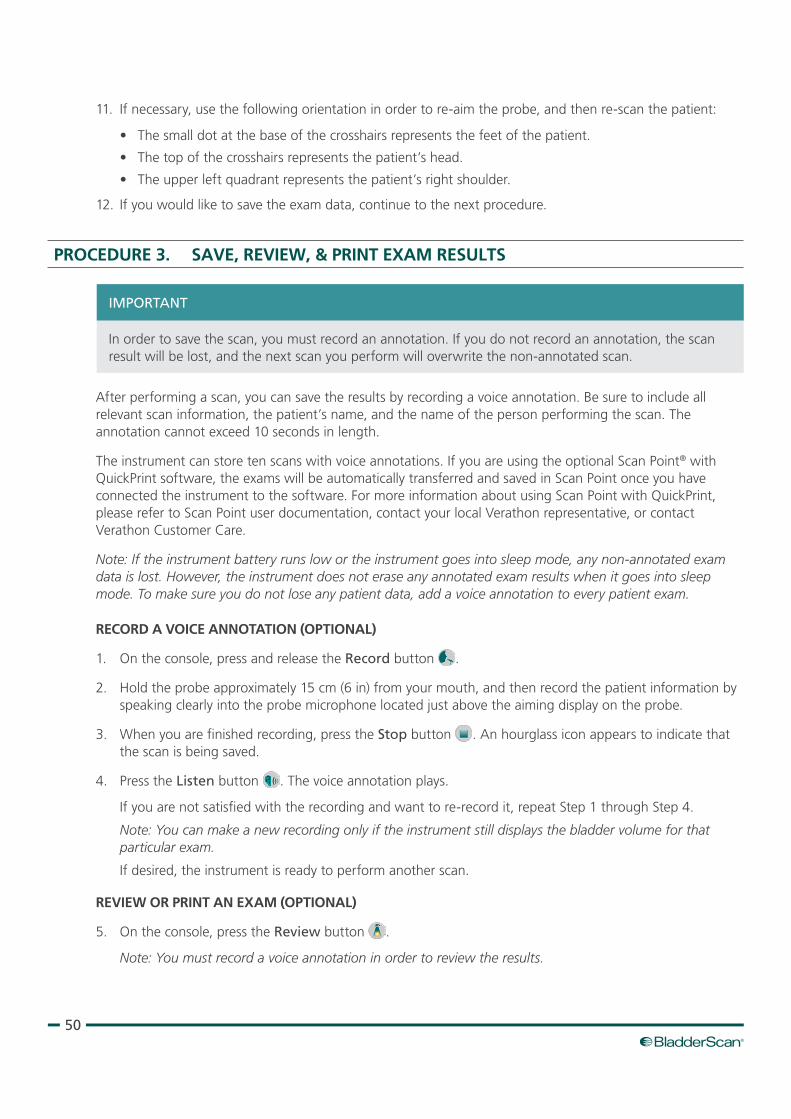
RECORd A VOICE ANNOTATION (OPTIONAL)
1. On the console, press and release the Record button .
2. Hold the probe approximately 15 cm (6 in) from your mouth, and then record the patient information by speaking clearly into the probe microphone located just above the aiming display on the probe.
3. When you are finished recording, press the Stop button . An hourglass icon appears to indicate that the scan is being saved.
4. Press the Listen button . The voice annotation plays.
If you are not satisfied with the recording and want to re‑record it, repeat Step 1 through Step 4.
Note: You can make a new recording only if the instrument still displays the bladder volume for that particular exam.
If desired, the instrument is ready to perform another scan.
REVIEW OR PRINT AN EXAM (OPTIONAL)
5. On the console, press the Review button .
Note: You must record a voice annotation in order to review the results.
51Operations & Maintenance Manual: Using the Device
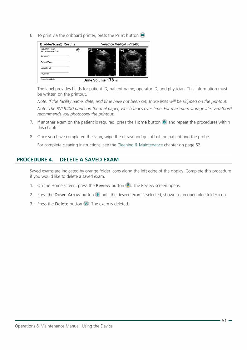
6. To print via the onboard printer, press the Print button .
The label provides fields for patient ID, patient name, operator ID, and physician. This information must be written on the printout.
Note: If the facility name, date, and time have not been set, those lines will be skipped on the printout.
Note: The BVI 9400 prints on thermal paper, which fades over time. For maximum storage life, Verathon® recommends you photocopy the printout.
7. If another exam on the patient is required, press the Home button and repeat the procedures within this chapter.
8. Once you have completed the scan, wipe the ultrasound gel off of the patient and the probe.
For complete cleaning instructions, see the Cleaning & Maintenance chapter on page 52.
PROCEdURE 4. dELETE A SAVEd EXAM
Saved exams are indicated by orange folder icons along the left edge of the display. Complete this procedure if you would like to delete a saved exam.
1. On the Home screen, press the Review button . The Review screen opens.
2. Press the Down Arrow button until the desired exam is selected, shown as an open blue folder icon.
3. Press the Delete button . The exam is deleted.

52
CLEANING & MAINTENANCE
This product may only be cleaned and disinfected by using the approved processes provided in this manual. Cleaning and disinfection methods listed are recommended by Verathon based on compatibility with component materials.
WARNING
Availability of cleaning and disinfection products varies by country, and Verathon is unable to test products in every market. For more information, please contact Verathon Customer Care or your local representative. For additional contact information, visit verathon.com/support.
WARNING
Ensure that you follow the manufacturer’s instructions for handling and disposing of the cleaning and disinfection solutions provided in this manual.
WARNING
Cleaning is critical to ensuring the component is ready for disinfection. Failure to properly clean the device could result in a contaminated instrument after completing the disinfection procedure.
WARNING
Cleaning and disinfecting the instrument is an important part of using and maintaining the device. Prior to each use, ensure the instrument has been cleaned and disinfected according to the following procedures.
BEST PRACTICES
Cleaning is the removal of all visible soil or contaminants from the exterior surfaces of the device, and disinfection is the process of destroying pathogenic organisms or rendering them inert. When cleaning, ensure all foreign matter is removed. This allows the active ingredients of the chosen disinfection method to reach all the surfaces of the device.
To significantly reduce the amount of effort needed to clean the system, do not let contaminants dry on any system component. Contaminants tend to become securely attached to solid surfaces when dried, making removal more difficult.
Change gloves as directed in the procedure or if gloves become soiled.
53Operations & Maintenance Manual: Cleaning & Maintenance
When using a wipe cleaning or disinfection method, please adhere to the following best practices:
• Always wipe in the direction from a clean surface towards a dirty surface.
• Minimize overlap on the wiping pattern.
• If a wipe becomes dry or soiled, replace it with a fresh one.
• Do not reuse dry or soiled wipes.
• Use a new wipe as instructed in the cleaning and disinfection procedures.
COMPATIBILITY & AVAILABILITY
The availability of the cleaning and disinfection products provided in this manual varies by region; ensure that you select products in accordance with your local laws and regulations.
The following solutions have demonstrated material compatibility with the system components, but they have not been tested for efficacy. Results with compatible solutions may vary based on exposure periods and device handling. For guidance on biological effectiveness of the disinfectant, refer to the instructions from the manufacturer:
• A‑456® II Disinfectant
• Accel® TB Wipes
• Cavicide®
• CaviWipes®
• Chloro‑Sol Spray®
• Clorox® Germicidal Wipes
• Sani‑Cloth® Bleach Wipes
• Sani‑Cloth® Germicidal Wipes
• Sani‑Cloth® Plus Germicical Wipes
• Sporicidin® Disinfecting Towelettes
• T‑Spray II®
PROCEdURE 1. CLEAN & dISINFECT THE INSTRUMENT
Failure to heed the following may cause device damage not covered by the warranty:
• Do not immerse the instrument in the disinfectant solution.
• Do not subject any part of the instrument to steam, ethylene oxide, radiation, or similar methods of sterilization or autoclaving.
• Do not use CidexPlus® to disinfect the instrument. CidexPlus will damage the plastic enclosure.
IMPORTANT
Use this procedure in order to clean the BladderScan BVI 6100 instrument. Review the information in the Best Practices and Compatibility & Availability sections before completing this procedure.
CLEAN THE INSTRUMENT
1. Put on new gloves.
2. After every exam, Using a dry paper towel or soft cloth, wipe any ultrasound gel completely off the scanhead.
3. Use a soft, moistened cloth to remove particulate matter or body fluids that remain on the instrument.
4. Allow the instrument to air dry or towel dry with a clean dry cloth before disinfecting.
5. Continue to the following section, Disinfect the Instrument. Low‑level disinfection of the scanhead is required between uses.
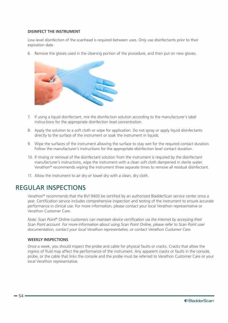
54
dISINFECT THE INSTRUMENT
Low‑level disinfection of the scanhead is required between uses. Only use disinfectants prior to their expiration date.
6. Remove the gloves used in the cleaning portion of the procedure, and then put on new gloves.
7. If using a liquid disinfectant, mix the disinfection solution according to the manufacturer’s label instructions for the appropriate disinfection level concentration.
8. Apply the solution to a soft cloth or wipe for application. Do not spray or apply liquid disinfectants directly to the surface of the instrument or soak the instrument in liquids.
9. Wipe the surfaces of the instrument allowing the surface to stay wet for the required contact duration. Follow the manufacturer’s instructions for the appropriate disinfection level contact duration.
10. If rinsing or removal of the disinfectant solution from the instrument is required by the disinfectant manufacturer’s instructions, wipe the instrument with a clean soft cloth dampened in sterile water. Verathon® recommends wiping the instrument three separate times to remove all residual disinfectant.
11. Allow the instrument to air dry or towel dry with a clean, dry cloth.
REGULAR INSPECTIONSVerathon® recommends that the BVI 9400 be certified by an authorized BladderScan service center once a year. Certification service includes comprehensive inspection and testing of the instrument to ensure accurate performance in clinical use. For more information, please contact your local Verathon representative or Verathon Customer Care.
Note: Scan Point® Online customers can maintain device certification via the Internet by accessing their Scan Point account. For more information about using Scan Point Online, please refer to Scan Point user documentation, contact your local Verathon representative, or contact Verathon Customer Care.
WEEKLY INSPECTIONS
Once a week, you should inspect the probe and cable for physical faults or cracks. Cracks that allow the ingress of fluid may affect the performance of the instrument. Any apparent cracks or faults in the console, probe, or the cable that links the console and the probe must be referred to Verathon Customer Care or your local Verathon representative.
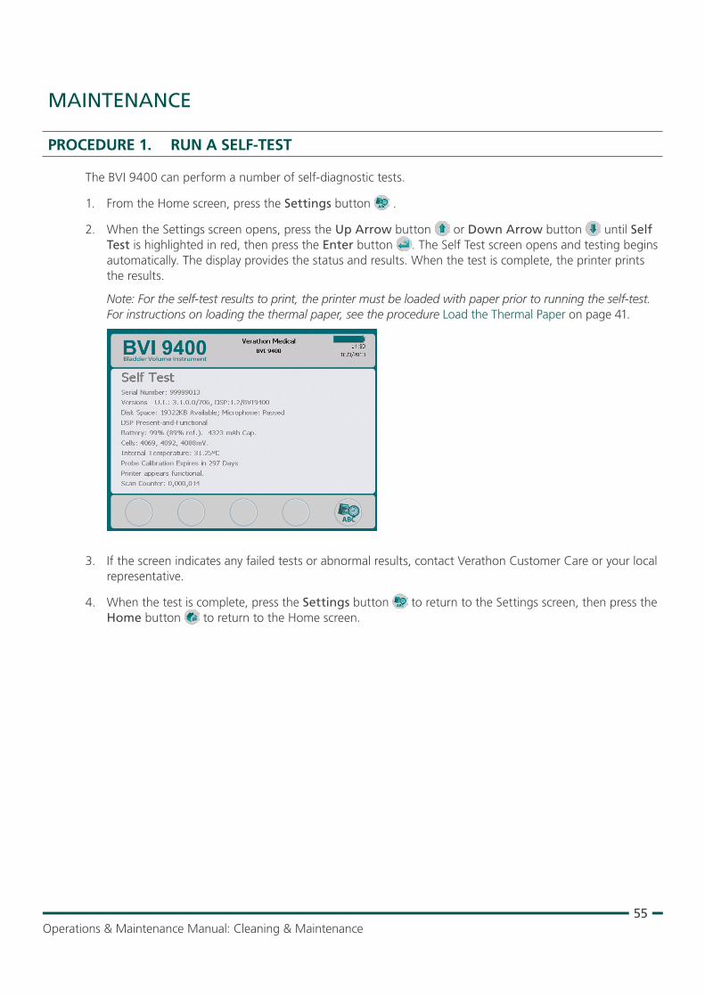
55Operations & Maintenance Manual: Cleaning & Maintenance
MAINTENANCE
PROCEdURE 1. RUN A SELF‑TEST
The BVI 9400 can perform a number of self‑diagnostic tests.
1. From the Home screen, press the Settings button .
2. When the Settings screen opens, press the Up Arrow button or Down Arrow button until Self Test is highlighted in red, then press the Enter button . The Self Test screen opens and testing begins automatically. The display provides the status and results. When the test is complete, the printer prints the results.
Note: For the self‑test results to print, the printer must be loaded with paper prior to running the self‑test. For instructions on loading the thermal paper, see the procedure Load the Thermal Paper on page 41.
3. If the screen indicates any failed tests or abnormal results, contact Verathon Customer Care or your local representative.
4. When the test is complete, press the Settings button to return to the Settings screen, then press the Home button to return to the Home screen.
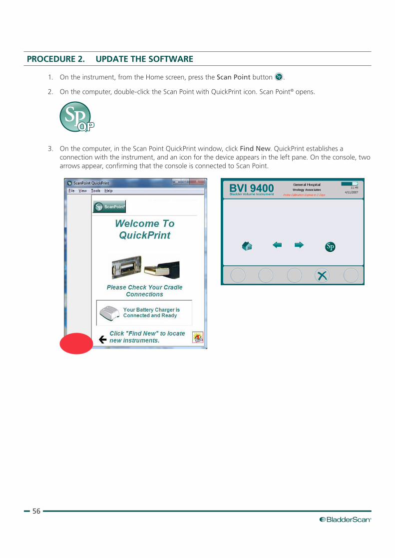
56
PROCEdURE 2. UPdATE THE SOFTWARE
1. On the instrument, from the Home screen, press the Scan Point button .
2. On the computer, double‑click the Scan Point with QuickPrint icon. Scan Point® opens.
3. On the computer, in the Scan Point QuickPrint window, click Find New. QuickPrint establishes a connection with the instrument, and an icon for the device appears in the left pane. On the console, two arrows appear, confirming that the console is connected to Scan Point.
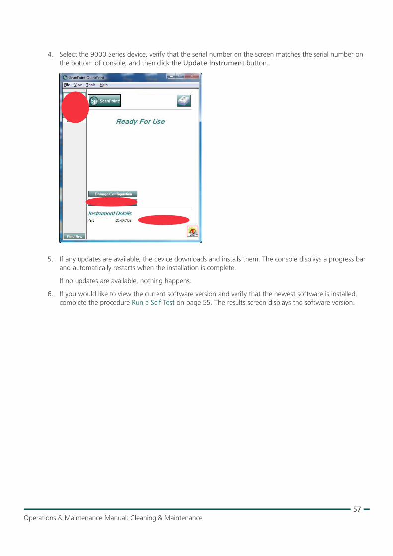
57Operations & Maintenance Manual: Cleaning & Maintenance
4. Select the 9000 Series device, verify that the serial number on the screen matches the serial number on the bottom of console, and then click the Update Instrument button.
5. If any updates are available, the device downloads and installs them. The console displays a progress bar and automatically restarts when the installation is complete.
If no updates are available, nothing happens.
6. If you would like to view the current software version and verify that the newest software is installed, complete the procedure Run a Self‑Test on page 55. The results screen displays the software version.
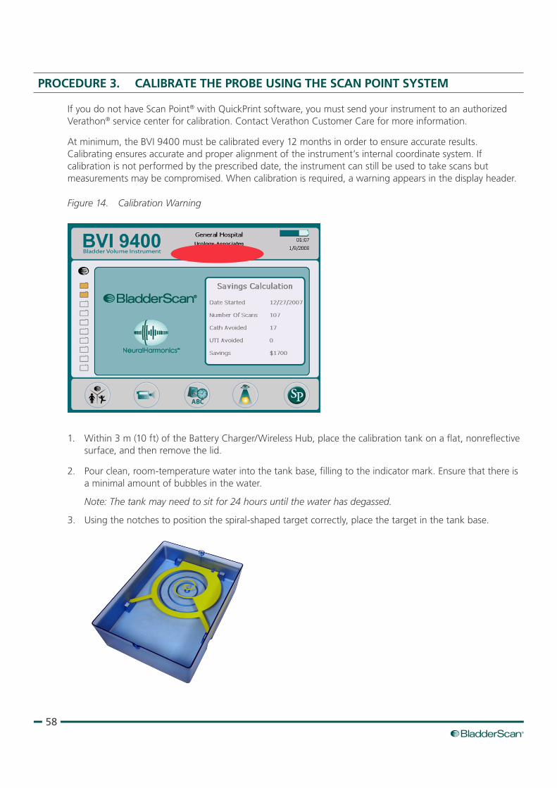
58
PROCEdURE 3. CALIBRATE THE PROBE USING THE SCAN POINT SYSTEM
If you do not have Scan Point® with QuickPrint software, you must send your instrument to an authorized Verathon® service center for calibration. Contact Verathon Customer Care for more information.
At minimum, the BVI 9400 must be calibrated every 12 months in order to ensure accurate results. Calibrating ensures accurate and proper alignment of the instrument’s internal coordinate system. If calibration is not performed by the prescribed date, the instrument can still be used to take scans but measurements may be compromised. When calibration is required, a warning appears in the display header.
Figure 14. Calibration Warning
1. Within 3 m (10 ft) of the Battery Charger/Wireless Hub, place the calibration tank on a flat, nonreflective surface, and then remove the lid.
2. Pour clean, room‑temperature water into the tank base, filling to the indicator mark. Ensure that there is a minimal amount of bubbles in the water.
Note: The tank may need to sit for 24 hours until the water has degassed.
3. Using the notches to position the spiral‑shaped target correctly, place the target in the tank base.
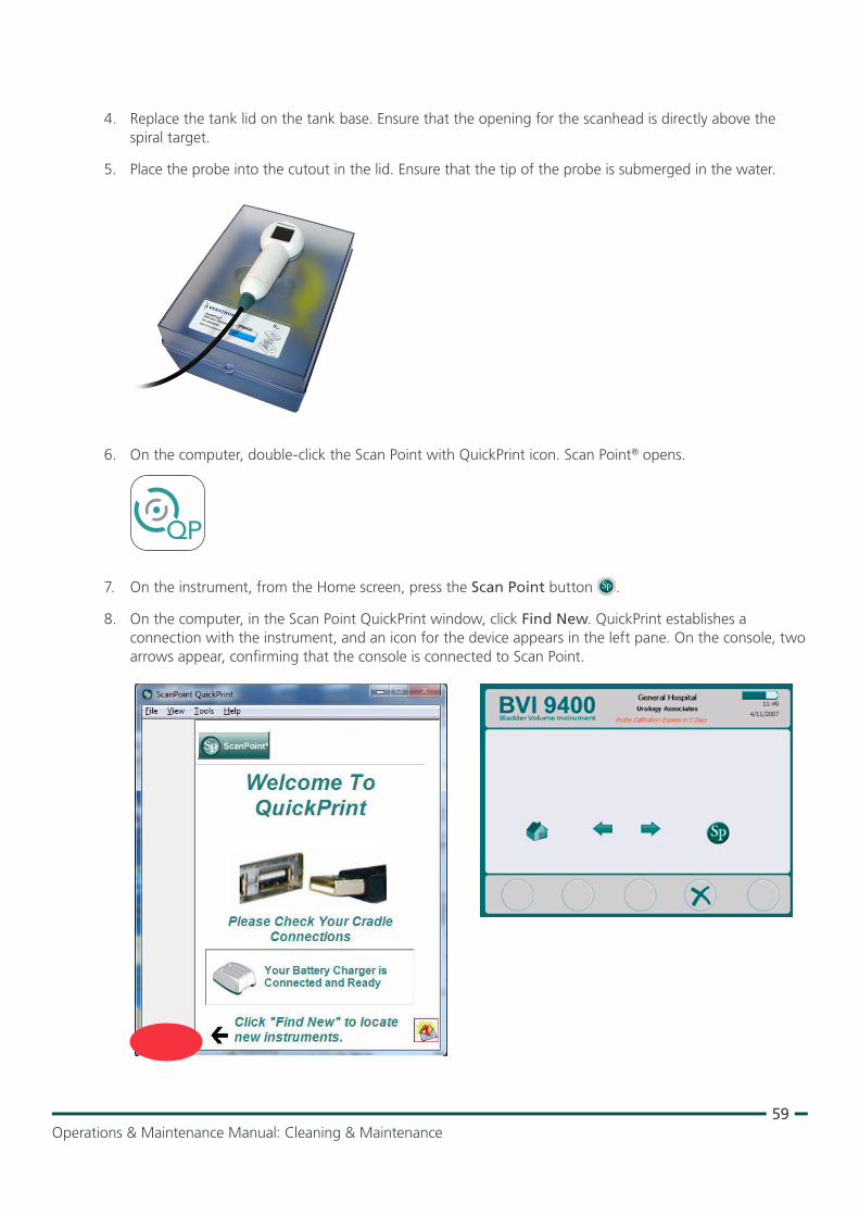
59Operations & Maintenance Manual: Cleaning & Maintenance
4. Replace the tank lid on the tank base. Ensure that the opening for the scanhead is directly above the spiral target.
5. Place the probe into the cutout in the lid. Ensure that the tip of the probe is submerged in the water.
6. On the computer, double‑click the Scan Point with QuickPrint icon. Scan Point® opens.
7. On the instrument, from the Home screen, press the Scan Point button .
8. On the computer, in the Scan Point QuickPrint window, click Find New. QuickPrint establishes a connection with the instrument, and an icon for the device appears in the left pane. On the console, two arrows appear, confirming that the console is connected to Scan Point.
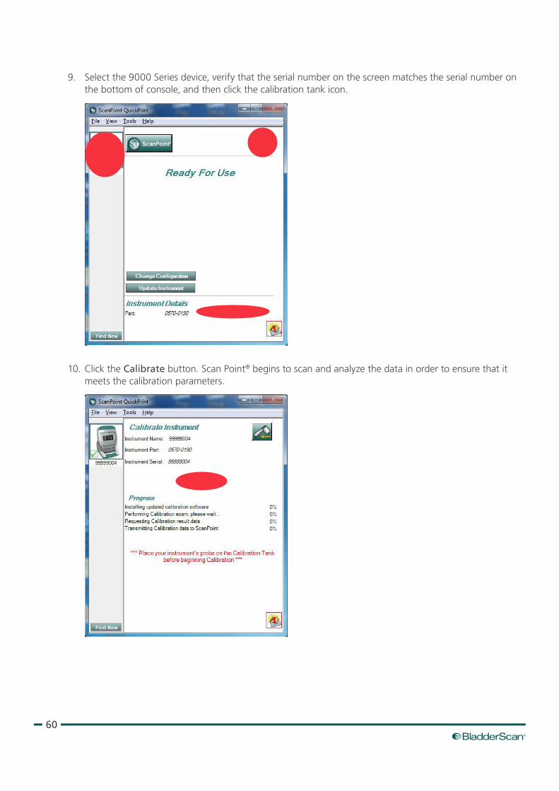
60
9. Select the 9000 Series device, verify that the serial number on the screen matches the serial number on the bottom of console, and then click the calibration tank icon.
10. Click the Calibrate button. Scan Point® begins to scan and analyze the data in order to ensure that it meets the calibration parameters.
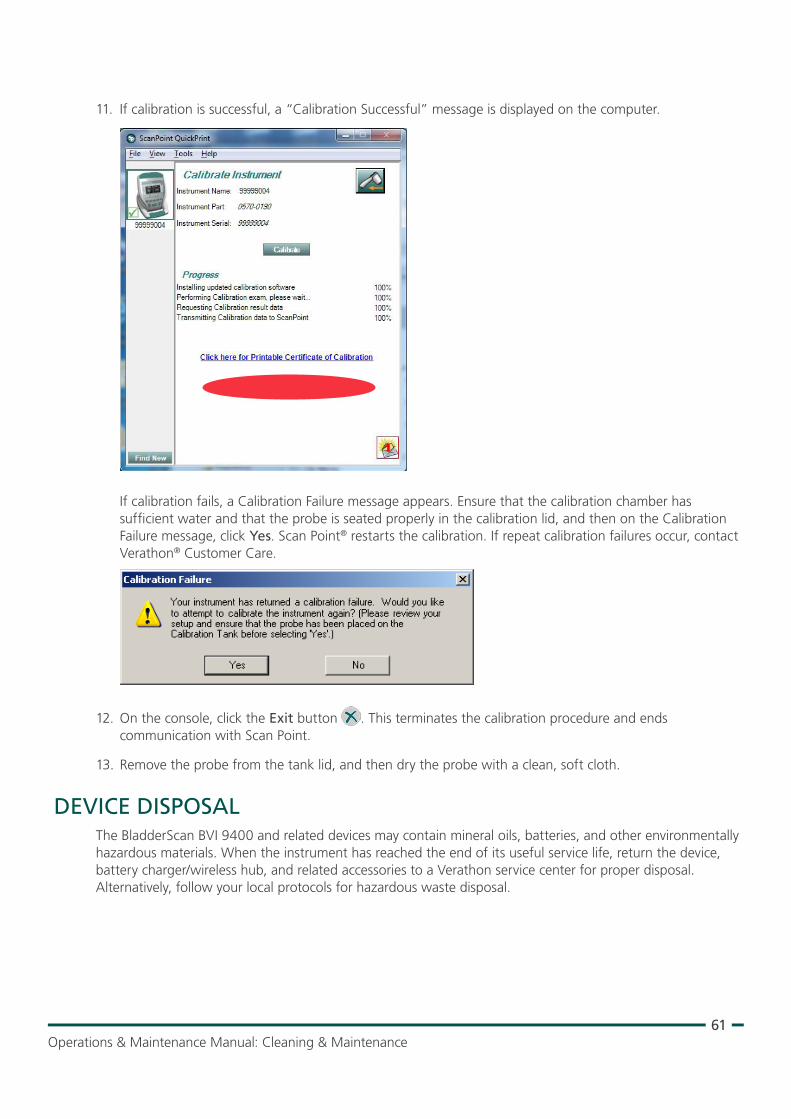
61Operations & Maintenance Manual: Cleaning & Maintenance
11. If calibration is successful, a “Calibration Successful” message is displayed on the computer.
If calibration fails, a Calibration Failure message appears. Ensure that the calibration chamber has sufficient water and that the probe is seated properly in the calibration lid, and then on the Calibration Failure message, click Yes. Scan Point® restarts the calibration. If repeat calibration failures occur, contact Verathon® Customer Care.
12. On the console, click the Exit button . This terminates the calibration procedure and ends communication with Scan Point.
13. Remove the probe from the tank lid, and then dry the probe with a clean, soft cloth.
DEVICE DISPOSALThe BladderScan BVI 9400 and related devices may contain mineral oils, batteries, and other environmentally hazardous materials. When the instrument has reached the end of its useful service life, return the device, battery charger/wireless hub, and related accessories to a Verathon service center for proper disposal. Alternatively, follow your local protocols for hazardous waste disposal.
62
TROUBLESHOOTING
HELP RESOURCESVerathon® provides an extensive array of customer service resources, described in the table below.
RESOURCE DESCRIPTION
In‑service CD or USBThe CD or USB flash drive included with your system provides instructions for using the instrument.
Onboard training modulesTraining modules installed on your BladderScan are available by pressing the Tutorial button from the Home screen.
Phone and Email SupportPlease refer to verathon.com/support for a list of phone numbers and locations. To request information on our products, or to schedule an on‑site demo, please fill out the form found at verathon.com/contact‑us
DEVICE REPAIRThe BladderScan BVI 9400, probe, and battery charger/wireless hub are completely sealed. There are no user‑serviceable components. Verathon does not make available any type of circuit diagrams, component parts lists, descriptions, or other information that would be required for repairing the device and related accessories.
Premium warranty customers have access to a loaner unit and free shipping options that vary according to the service plan.
If you have any questions, please contact your local Verathon representative or Verathon Customer Care.
WARRANTYVerathon® products and software are warranted against defects in material and workmanship according to the Terms and Conditions of Sale. This limited warranty applies for one (1) year from the date of shipment from Verathon and applies only to the original purchaser of the system. Warranty coverage applies to the following system components:
• BladderScan console
• BladderScan probe
• Battery Charger/Wireless Hub
Additional reusable components purchased either singularly or as a part of a system are warranted separately. Consumable items are not covered under this warranty.
For more information about your warranty or to purchase a Premium Total Customer CareSM warranty that extends the limited warranty on your system, please contact Verathon Customer Care or your local representative.
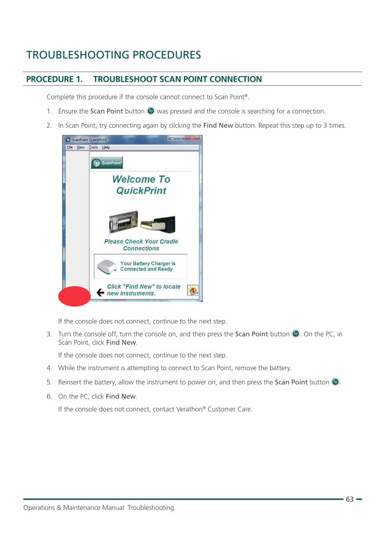
63Operations & Maintenance Manual: Troubleshooting
TROUBLESHOOTING PROCEDURES
PROCEdURE 1. TROUBLESHOOT SCAN POINT CONNECTION
Complete this procedure if the console cannot connect to Scan Point®.
1. Ensure the Scan Point button was pressed and the console is searching for a connection.
2. In Scan Point, try connecting again by clicking the Find New button. Repeat this step up to 3 times.
If the console does not connect, continue to the next step.
3. Turn the console off, turn the console on, and then press the Scan Point button . On the PC, in Scan Point, click Find New.
If the console does not connect, continue to the next step.
4. While the instrument is attempting to connect to Scan Point, remove the battery.
5. Reinsert the battery, allow the instrument to power on, and then press the Scan Point button .
6. On the PC, click Find New.
If the console does not connect, contact Verathon® Customer Care.
64
PROCEdURE 2. TROUBLESHOOT POWER ISSUES
If the instrument does not turn on, this is usually due to a dead or discharged battery and can be remedied by replacing the dead battery with a charged battery.
When the battery charge is too low to allow normal operation (but not too low to permit operation of the internal circuitry) the device displays the following message:
Battery charge level is too low for instrument operation. Recharge before next use.
In this case, the battery must be recharged or replaced with a charged one.
If the instrument has stopped responding even with a new battery, perform a full reset by removing and reinserting the battery. If the instrument still does not respond, contact Verathon® Customer Care.
PROCEdURE 3. INSTRUMENT TOO HOT
The BVI 9400 displays the message “Too hot” if the print head overheats. In this case, turn off the BVI 9400 immediately. This condition may be the result of a paper jam.
PROCEdURE 4. CLEAR A PAPER JAM
Complete this procedure if the paper will not advance through the printer.
1. Open the printer door on the back of the console and clear the paper jam.
2. Ensure that the thermal paper is loaded correctly according to the instructions in the procedure Load the Thermal Paper on page 41.
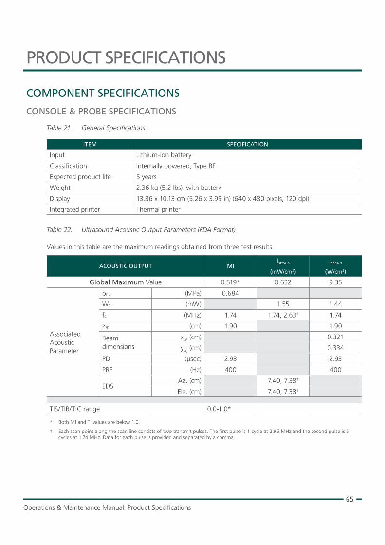
65Operations & Maintenance Manual: Product Specifications
PRODUCT SPECIFICATIONS
COMPONENT SPECIFICATIONS
CONSOLE & PROBE SPECIFICATIONS
Table 21. General Specifications
ITEM SPECIFICATION
Input Lithium‑ion battery
Classification Internally powered, Type BF
Expected product life 5 years
Weight 2.36 kg (5.2 lbs), with battery
Display 13.36 x 10.13 cm (5.26 x 3.99 in) (640 x 480 pixels, 120 dpi)
Integrated printer Thermal printer
Table 22. Ultrasound Acoustic Output Parameters (FDA Format)
Values in this table are the maximum readings obtained from three test results.
ACOUSTIC OUTPUT MIISPTA.3
(mW/cm2)
ISPPA.3
(W/cm2)
Global Maximum Value 0.519* 0.632 9.35
Associated Acoustic Parameter
pr.3 (MPa) 0.684
Wo (mW) 1.55 1.44
fc (MHz) 1.74 1.74, 2.63† 1.74
zsp (cm) 1.90 1.90
Beam dimensions
x‑6 (cm) 0.321
y‑6 (cm) 0.334
PD (µsec) 2.93 2.93
PRF (Hz) 400 400
EDSAz. (cm) 7.40, 7.38†
Ele. (cm) 7.40, 7.38†
TIS/TIB/TIC range 0.0‑1.0*
* Both MI and TI values are below 1.0.
† Each scan point along the scan line consists of two transmit pulses. The first pulse is 1 cycle at 2.95 MHz and the second pulse is 5 cycles at 1.74 MHz. Data for each pulse is provided and separated by a comma.
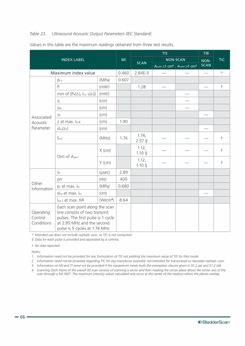
66
Table 23. Ultrasound Acoustic Output Parameters (IEC Standard)
Values in this table are the maximum readings obtained from three test results.
INDEX LABEL MI
TIS TIB
TICSCAN
NON‑SCAN NON‑SCANAAPRT ≤1 cm² AAPRT >1 cm²
Maximum index value 0.460 2.84E‑3 — — — *
Associated Acoustic Parameter
pr.a (MPa) 0.607
P (mW) 1.28 — — †
min of [Pα(zs), Ita, α(zs)] (mW) —
zs (cm) —
zbp (cm) —
zb (cm) —
z at max. Ipi,α (cm) 1.90
deq(zb) (cm) —
fawf (MHz) 1.741.74,
2.57 §— — — †
Dim of Aaprt
X (cm)1.12,
1.10 §— — — †
Y (cm)1.12,
1.10 §— — — †
Other Information
td (μsec) 2.89
prr (Hz) 400
pr at max. Ipi (MPa) 0.680
deq at max. Ipi (cm) —
Ipa.3 at max. MI (W/cm²) 8.64
Operating Control Conditions
Each scan point along the scan line consists of two transmit pulses. The first pulse is 1 cycle at 2.95 MHz and the second pulse is 5 cycles at 1.74 MHz
* Intended use does not include cephalic uses, so TIC is not computed.§ Data for each pulse is provided and seporated by a comma.
† No data reported.
Notes:1. Information need not be provided for any formulation of TIS not yielding the maximum value of TIS for that mode.2. Information need not be provided regarding TIC for any transducer assembly not intended for transcranial or neonatal cephalic uses.3. Information on MI and TI need not be provided if the equipment meets both the exemption clauses given in 51.2 aa) and 51.2 dd).4. Scanning: Each frame of the overall 3D scan consists of scanning a sector and then rotating the sector plane about the center axis of the
scan through a full 360°. The maximum intensity values calculated only occur at the center of the rotation where the planes overlap.
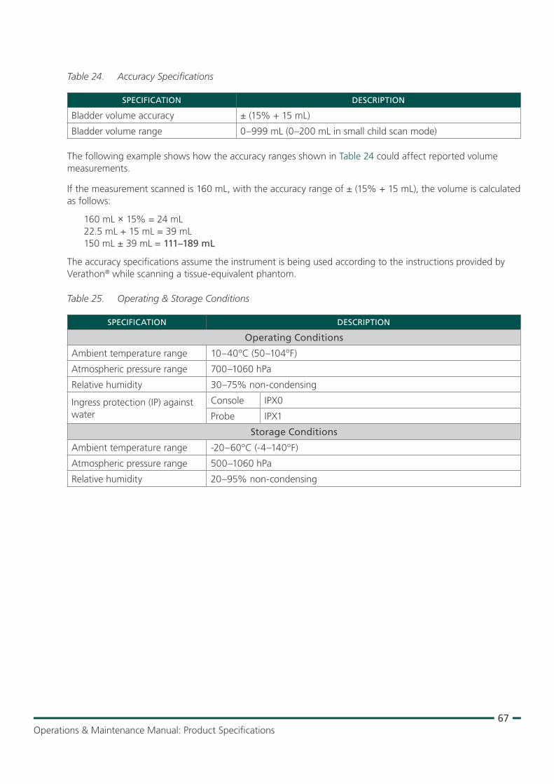
67Operations & Maintenance Manual: Product Specifications
Table 24. Accuracy Specifications
SPECIFICATION DESCRIPTION
Bladder volume accuracy ± (15% + 15 mL)
Bladder volume range 0–999 mL (0–200 mL in small child scan mode)
The following example shows how the accuracy ranges shown in Table 24 could affect reported volume measurements.
If the measurement scanned is 160 mL, with the accuracy range of ± (15% + 15 mL), the volume is calculated as follows:
160 mL × 15% = 24 mL 22.5 mL + 15 mL = 39 mL 150 mL ± 39 mL = 111–189 mL
The accuracy specifications assume the instrument is being used according to the instructions provided by Verathon® while scanning a tissue‑equivalent phantom.
Table 25. Operating & Storage Conditions
SPECIFICATION DESCRIPTION
Operating Conditions
Ambient temperature range 10–40ºC (50–104ºF)
Atmospheric pressure range 700–1060 hPa
Relative humidity 30–75% non‑condensing
Ingress protection (IP) against water
Console IPX0
Probe IPX1
Storage Conditions
Ambient temperature range ‑20–60ºC (‑4–140ºF)
Atmospheric pressure range 500–1060 hPa
Relative humidity 20–95% non‑condensing
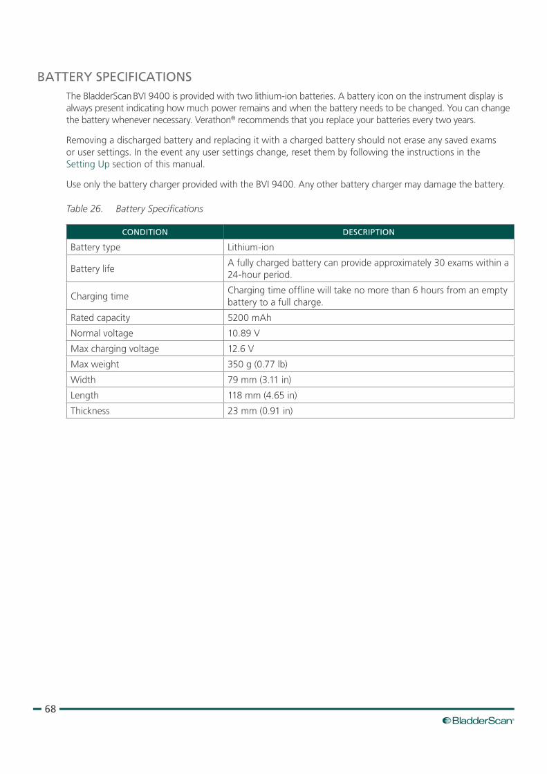
68
BATTERY SPECIFICATIONSThe BladderScan BVI 9400 is provided with two lithium‑ion batteries. A battery icon on the instrument display is always present indicating how much power remains and when the battery needs to be changed. You can change the battery whenever necessary. Verathon® recommends that you replace your batteries every two years.
Removing a discharged battery and replacing it with a charged battery should not erase any saved exams or user settings. In the event any user settings change, reset them by following the instructions in the Setting Up section of this manual.
Use only the battery charger provided with the BVI 9400. Any other battery charger may damage the battery.
Table 26. Battery Specifications
CONDITION DESCRIPTION
Battery type Lithium‑ion
Battery lifeA fully charged battery can provide approximately 30 exams within a 24‑hour period.
Charging timeCharging time offline will take no more than 6 hours from an empty battery to a full charge.
Rated capacity 5200 mAh
Normal voltage 10.89 V
Max charging voltage 12.6 V
Max weight 350 g (0.77 lb)
Width 79 mm (3.11 in)
Length 118 mm (4.65 in)
Thickness 23 mm (0.91 in)
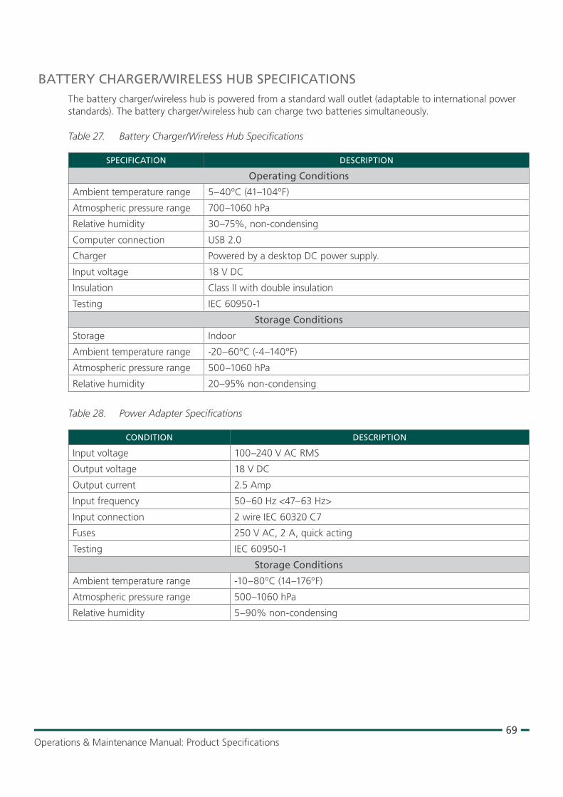
69Operations & Maintenance Manual: Product Specifications
BATTERY CHARGER/WIRELESS HUB SPECIFICATIONSThe battery charger/wireless hub is powered from a standard wall outlet (adaptable to international power standards). The battery charger/wireless hub can charge two batteries simultaneously.
Table 27. Battery Charger/Wireless Hub Specifications
SPECIFICATION DESCRIPTION
Operating Conditions
Ambient temperature range 5–40ºC (41–104ºF)
Atmospheric pressure range 700–1060 hPa
Relative humidity 30–75%, non‑condensing
Computer connection USB 2.0
Charger Powered by a desktop DC power supply.
Input voltage 18 V DC
Insulation Class II with double insulation
Testing IEC 60950‑1
Storage Conditions
Storage Indoor
Ambient temperature range ‑20–60ºC (‑4–140ºF)
Atmospheric pressure range 500–1060 hPa
Relative humidity 20–95% non‑condensing
Table 28. Power Adapter Specifications
CONDITION DESCRIPTION
Input voltage 100–240 V AC RMS
Output voltage 18 V DC
Output current 2.5 Amp
Input frequency 50–60 Hz <47–63 Hz>
Input connection 2 wire IEC 60320 C7
Fuses 250 V AC, 2 A, quick acting
Testing IEC 60950‑1
Storage Conditions
Ambient temperature range ‑10–80ºC (14–176ºF)
Atmospheric pressure range 500–1060 hPa
Relative humidity 5–90% non‑condensing

70
BLUETOOTH WIRELESS TECHNOLOGYThe Bluetooth® technology used in the BladderScan BVI 9400 is compliant with:
• Bluetooth Specification as defined and approved by The Bluetooth Special Interests Group.
• Logo certification with Bluetooth wireless technology as defined by The Bluetooth Special Interest Group.
ELECTROMAGNETIC COMPATIBILITYThe BladderScan BVI 9400 system is designed to be in compliance with IEC 60601‑1‑2:2007, which contains electromagnetic compatibility (EMC) requirements for medical electrical equipment. The limits for emissions and immunity specified in this standard are designed to provide reasonable protection against harmful interference in a typical medical installation.
The BladderScan BVI 9400 system complies with the applicable essential performance requirements specified in IEC 60601‑1 and IEC 60601‑2‑37. Results of immunity testing show that the essential performance of the system is not affected under the test conditions described in the following tables. For more information about the essential performance of the BladderScan BVI 9400 system, see Essential Performance on page 2.
ELECTROMAGNETIC EMISSIONS
Table 29. Guidance and Manufacturer’s Declaration—Electromagnetic Emissions
The system is intended for use in the electromagnetic environment specified below. The customer or the user of the system should ensure that it is used in such an environment.
EMISSIONS TEST COMPLIANCE ELECTROMAGNETIC ENVIRONMENT – GUIDANCE
RF emissions CISPR 11
Group 1The BladderScan BVI 9400 system uses RF energy only for its internal function. Therefore, its RF emissions are very low and are not likely to cause any interference in nearby electronic equipment.
RF emissions CISPR 11
Class A
The BladderScan BVI 9400 system is suitable for use in all establishments other than domestic and those directly connected to the public low‑voltage power supply network that supplies buildings used for domestic purposes.
Harmonic emissions IEC 61000‑3‑2
Class A
Voltage fluctuations/flicker emissions IEC 61000‑3‑3
Complies

71Operations & Maintenance Manual: Product Specifications
ELECTROMAGNETIC IMMUNITY
Table 30. Guidance and Manufacturer’s Declaration —Electromagnetic Immunity
The system is intended for use in the electromagnetic environment specified below. The customer or the user of the system should ensure that it is used in such an environment.
IMMUNITY TESTS IEC 60601 TEST LEVEL COMPLIANCE LEVEL
ELECTROMAGNETIC ENVIRONMENT – GUIDANCE
Electrostatic discharge (ESD)
IEC 61000‑4‑2
± 6 kV contact
± 8 kV airIn compliance
Floors should be wood, concrete, or ceramic tile. If floors are covered with synthetic material, the relative humidity should be at least 30%.
Electrical fast transient/burst
IEC 61000‑4‑4
± 2 kV for power supply lines
± 1 kV for input/output lines
In complianceMains power quality should be that of a typical commercial or hospital environment.
Surge
IEC 61000‑4‑5
± 1 kV line(s) to line(s)
± 2 kV line(s) to earthIn compliance
Mains power quality should be that of a typical commercial or hospital environment.
Voltage dips, short interruptions and voltage variations on power supply input lines
IEC 61000‑4‑11
<5% Ut (>95% dip in Ut) for 0.5 cycle
40% Ut (60% dip in Ut) for 5 cycles
70% Ut (30% dip in Ut) for 25 cycles
<5% Ut (>95% dip in Ut) for 5 s
In compliance
Mains power quality should be that of a typical commercial or hospital environment. If the user of the BladderScan BVI 9400 system requires continued operation during power mains interruptions, it is recommended that the BladderScan BVI 9400 system be powered from an uninterruptible power supply or a battery.
Power frequency (50/60 Hz) magnetic field
IEC 61000‑4‑8
3 A/m In compliance
Power frequency magnetic fields should be at levels characteristic of a typical location in a typical commercial or hospital environment.
Conducted RF IEC 61000‑4‑6
3 Vrms 150 kHz to 80 MHz
3 V
Portable and mobile RF communications equipment should be used no closer to any part of the BladderScan BVI 9400 system, including cables, than the recommended separation distance calculated from the equation applicable to the frequency of the transmitter.
Recommended separation distance d (m)
d=1.2 √P
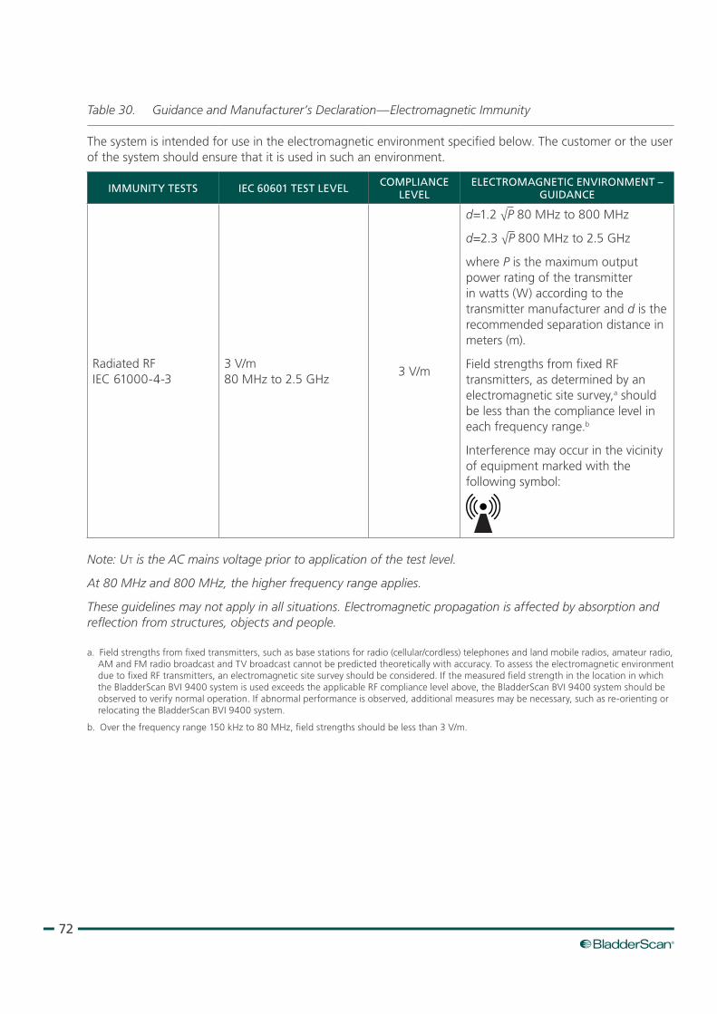
72
Table 30. Guidance and Manufacturer’s Declaration —Electromagnetic Immunity
The system is intended for use in the electromagnetic environment specified below. The customer or the user of the system should ensure that it is used in such an environment.
IMMUNITY TESTS IEC 60601 TEST LEVEL COMPLIANCE LEVEL
ELECTROMAGNETIC ENVIRONMENT – GUIDANCE
Radiated RF IEC 61000‑4‑3
3 V/m 80 MHz to 2.5 GHz
3 V/m
d=1.2 √P 80 MHz to 800 MHz
d=2.3 √P 800 MHz to 2.5 GHz
where P is the maximum output power rating of the transmitter in watts (W) according to the transmitter manufacturer and d is the recommended separation distance in meters (m).
Field strengths from fixed RF transmitters, as determined by an electromagnetic site survey,a should be less than the compliance level in each frequency range.b
Interference may occur in the vicinity of equipment marked with the following symbol:
Note: Ut is the AC mains voltage prior to application of the test level.
At 80 MHz and 800 MHz, the higher frequency range applies.
These guidelines may not apply in all situations. Electromagnetic propagation is affected by absorption and reflection from structures, objects and people.
a. Field strengths from fixed transmitters, such as base stations for radio (cellular/cordless) telephones and land mobile radios, amateur radio, AM and FM radio broadcast and TV broadcast cannot be predicted theoretically with accuracy. To assess the electromagnetic environment due to fixed RF transmitters, an electromagnetic site survey should be considered. If the measured field strength in the location in which the BladderScan BVI 9400 system is used exceeds the applicable RF compliance level above, the BladderScan BVI 9400 system should be observed to verify normal operation. If abnormal performance is observed, additional measures may be necessary, such as re‑orienting or relocating the BladderScan BVI 9400 system.
b. Over the frequency range 150 kHz to 80 MHz, field strengths should be less than 3 V/m.
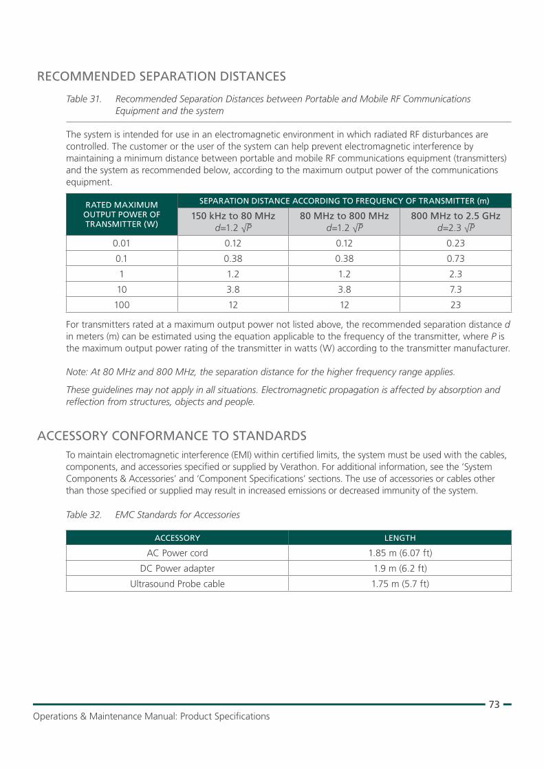
73Operations & Maintenance Manual: Product Specifications
RECOMMENDED SEPARATION DISTANCES
Table 31. Recommended Separation Distances between Portable and Mobile RF Communications Equipment and the system
The system is intended for use in an electromagnetic environment in which radiated RF disturbances are controlled. The customer or the user of the system can help prevent electromagnetic interference by maintaining a minimum distance between portable and mobile RF communications equipment (transmitters) and the system as recommended below, according to the maximum output power of the communications equipment.
RATED MAXIMUM OUTPUT POWER OF TRANSMITTER (W)
SEPARATION DISTANCE ACCORDING TO FREQUENCY OF TRANSMITTER (m)
150 kHz to 80 MHz d=1.2 √P
80 MHz to 800 MHz d=1.2 √P
800 MHz to 2.5 GHz d=2.3 √P
0.01 0.12 0.12 0.23
0.1 0.38 0.38 0.73
1 1.2 1.2 2.3
10 3.8 3.8 7.3
100 12 12 23
For transmitters rated at a maximum output power not listed above, the recommended separation distance d in meters (m) can be estimated using the equation applicable to the frequency of the transmitter, where P is the maximum output power rating of the transmitter in watts (W) according to the transmitter manufacturer.
Note: At 80 MHz and 800 MHz, the separation distance for the higher frequency range applies.
These guidelines may not apply in all situations. Electromagnetic propagation is affected by absorption and reflection from structures, objects and people.
ACCESSORY CONFORMANCE TO STANDARDSTo maintain electromagnetic interference (EMI) within certified limits, the system must be used with the cables, components, and accessories specified or supplied by Verathon. For additional information, see the ‘System Components & Accessories’ and ‘Component Specifications’ sections. The use of accessories or cables other than those specified or supplied may result in increased emissions or decreased immunity of the system.
Table 32. EMC Standards for Accessories
ACCESSORY LENGTH
AC Power cord 1.85 m (6.07 ft)
DC Power adapter 1.9 m (6.2 ft)
Ultrasound Probe cable 1.75 m (5.7 ft)

74
GLOSSARYThe following table provides definitions for specialized terms used in this manual or on the product itself. For a full list of caution, warning, and informational symbols used on this and other Verathon® products, please refer to the Verathon Symbol Glossary at verathon.com/symbols.
TERM DEFINITION
A Ampere
AC Alternating current
C Celsius
cm Centimeter
CSA Canadian Standards Association
DC Direct current
EMC Electromagnetic compatibility
EMI Electromagnetic interference
Essential performance The system performance necessary to achieve freedom from unacceptable risk
ESD Electrostatic discharge
F Fahrenheit
g Gram
GHz Gigahertz
HIPAA Health Insurance Portability and Accountability Act
hPa Hectopascal
Hz Hertz
IEC International Electrotechnical Commission
in Inch
ISM Industrial, scientific, and medical
ISPPA Spatial‑peak, pulse‑average intensity
ISPTA Spatial‑peak, temporal‑average intensity
kV Kilovolt
LAN Local area network
LCD Liquid crystal display
m Meter
mAh Milliampere‑hour
MDD Medical Device Directive
MHz Megahertz
MI Mechanical index
mm Millimeter
RF Radio frequency
RMS Root mean square
UL Underwriters Laboratories
Ultrasound field of view Cone‑shaped area in which the probe transmits ultrasound waves
V Volt
W Watt
WEEE Waste electrical and electronic equipment