Embed Size (px)
Citation preview
LBOMBAS DE ENGRANAJES
GEAR PUMPS
2
Índice / Index
Empresa ............................................................................. 3
Información general .......................................................... 4
Bomba de engranajes L / LN
Datos técnicos .............................................................. 5
Sistema de codificación ................................................ 8
Tipos de ejes motriz ............................................. 10
Tipos de tapas frontales ....................................... 11
Tipos de conexión tomas ..................................... 13
Configuraciones bombas estándar ............................. 14
Tapa tipo 10 .......................................................... 14
Tapa tipo 31 .......................................................... 15
Tapa tipo 09 .......................................................... 16
Tapa tipo 22-55 ..................................................... 17
Tapa tipo 23 .......................................................... 18
Tapa tipo 29-19-61 ............................................... 19
Configuraciones bombas especiales .......................... 20
Bomba de engranajes LG ..................................... 20
Bomba especial bajo nivel sonoro LZ ......................... 21
Otras opciones
Conexión con tomas T ................................................ 22
Tapa trasera para bombas reversibles ........................ 22
Bombas con polea - Tipos de polea ........................... 22
Bomba con eje flotante - Tapa tipo 10 ........................ 24
Bomba con eje flotante - Tapa tipo 23 ........................ 25
Bomba con válvula de aspiración-retención .............. 26
Bomba con válvula limitadora ..................................... 27
Bomba con repartidor de caudal ................................ 28
Bomba con regulador de caudal ................................ 29
Bombas múltiples
Bomba de engranajes LM / LNM (L+L / LN+LN) ........ 30
Bomba de engranajes LS / LNS (L+L0 / LN+L0) ........ 31
Recambios
Bomba L / LN .............................................................. 32
Bomba LM / LNM (L+L / LN+LN) ................................ 33
Bomba LS / LNS (L+L0 / LN+L0) ................................ 34
Company ............................................................................ 3
Information ......................................................................... 4
Gear pump L / LN
Technical data ............................................................... 5
Coding system .............................................................. 8
Drive shaft forms ................................................... 10
Front flange types ................................................. 11
Port connection forms .......................................... 13
Standard pump configurations ................................... 14
Front flange type 10 .............................................. 14
Front flange type 31 .............................................. 15
Front flange type 09 .............................................. 16
Front flange type 22-55 ........................................ 17
Front flange type 23 .............................................. 18
Front flange type 29-19-61 ................................... 19
Special pump configurations ...................................... 20
Gear pump LG ...................................................... 20
Special pump low noise level LZ................................. 21
Other options
Port connection form T ............................................... 22
Back cover for reversible pumps................................. 22
Pumps with pulley - Types of pulley ............................ 22
Pump with floating shaft - Front flange type 10 .......... 24
Pump with floating shaft - Front flange type 23 .......... 25
Pump with check valve ............................................... 26
Pump with relief valve ................................................. 27
Pump with priority flow valve ...................................... 28
Pump with flow control valve ...................................... 29
Multiple stages pumps
Gear pump LM / LNM (L+L / LN+LN) ......................... 30
Gear pump LS / LNS (L+L0 / LN+L0) .......................... 31
Spare parts
Pump L / LN ................................................................ 32
Pump LM / LNM (L+L / LN+LN) .................................. 33
Pump LS / LNS (L+L0 / LN+L0) .................................. 34
15,7
5
10,5
A
B
C
D
9,5
17
17
38,5
25,5
6,5
M12x
1.5
80 f7
34,5
100
72
= =
118,
5
90,5
9
Eje forma T / Shaft form TEje forma C / Shaft form C
25
17
M6x1
16
17,6
31
DIN-5482 (e9)B-17x14
Nº dientesNumber of teeth 9
16,5
h11
23,5
14
ConicidadTaper 1:5
Chaveta Key Ø16x3
14,5
E.C.A.F. 84
E.C.A.F. 62
Eje forma J / Shaft form JTapa tipo 23 / Front flange type 23
L
L0
3
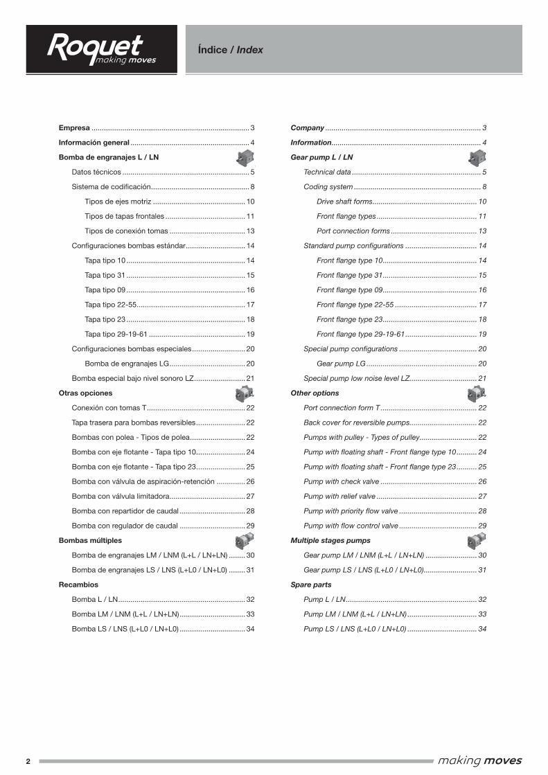
HISTORIA Más de medio siglo de trayectoria especializada en óleo-dinámica. Roquet es proveedor internacional en los sectores agrícola, naval, manutención, máquina-herramienta, automoción pesada, maquinaria de obras públicas, minería, eólica, alimentación, etc. Marca líder en España y una referencia importante en el ámbito internacional.
TECNOLOGÍA Roquet dispone de un importante departamento de diseño y desarrollo, con bancos de prueba de fatiga, nivel sonoro, resistencia a la corrosión, etc, apoyados por un avanzado laboratorio metalográfico. Se realizan grandes inversiones en centros de mecanizado de última generación para mantener una óptima calidad-productividad. La mayoría de piezas críticas (correderas, piezas de fundición, ejes de bomba, etc) se fabrican íntegramente en la propia empresa.
FIABILIDAD Una extensa gama de productos robustos y resistentes. Diseñados para rendir, construidos para durar. Todas las gamas de productos se someten a pruebas de vida en condiciones de trabajo realistas durante el diseño y desarrollo del producto. De esta forma se asegura su perfecta adaptación a las diversas aplicaciones finales tales como tractores, carretillas elevadoras, palas cargadoras, excavadoras, grúas, volquetes, muelles de carga... Se prueba el 100% de las unidades producidas, según procedimientos internos de prueba, antes de la expedición.
CAPACIDAD 400 profesionales en plantilla. Cinco plantas de producción con una superficie cubierta de 40.000 m². Producción actual: 180.000 bombas, 300.000 cuerpos de distribuidor y 500.000 cilindros. Una red comercial de distribución extendida por más de 35 países de los 5 continentes.
HISTORY Over fifty years experience in fluid power. Supplier to international manufactures of agricultural, construction, mining, mechanical handling, machine-tool and food machinery. Main supplier to the Spanish market with rapidly increasing presence in European and world markets.
TECHNOLOGY Roquet has a large design and development department with substantial fatigue, noise, corrosion-resistance, cleanliness and testing facilites, backed by a well-equipped metallurgical laboratory.
RELIABILITY A broad range of robust products: designed to perform, built to last. All products ranges life-tested under realistic conditions during development to ensure their suitability for use in applications such as tractors, fork-lift trucks, loaders, excavators, cranes, dumpers, dock-levellers... Each and every product tested to a stringent test specification prior to shipment.
CAPABILITY 400 well trained empoyees. Five factories with a total floor area of 40.000m² Current production 180.000 pumps, 300.000 control valve bodies and 500.000 cylinders. Distribution network in over 35 countries.
Empresa / Company
4
Información general / Information
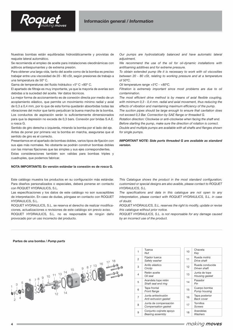
Nuestras bombas están equilibradas hidrostáticamente y provistas de reajuste lateral automático.Se recomienda el empleo de aceite para instalaciones oleodinámicas con aditivos antiespumantes y de extrema presión.Para obtener una larga vida, tanto del aceite como de la bomba es preciso trabajar entre una viscosidad de 20 - 80 cSt, según presiones de trabajo a una temperatura de 50º C.Gama de temperaturas del fluido hidráulico +5º C +80º C.El apartado de filtraje es muy importante, ya que la mayoría de averías son debidas a la suciedad del aceite. Ver datos técnicos.La mejor forma de accionamiento es de conexión directa por medio de un acoplamiento elástico, que permite un movimiento mínimo radial y axial de 0,3 a 0,4 mm, por lo que de esta forma quedarán absorbidas todas las vibraciones del motor que tanto perjudican la buena marcha de la bomba.Los conductos de aspiración serán lo suficientemente dimensionados para que la depresión no exceda de 0,3 bars. Conexión por bridas S.A.E. o rosca G.Sentido de giro derecha o izquierda, mirando la bomba por el lado del eje.Antes de poner por primera vez la bomba en marcha, asegurarse que el sentido de giro es el correcto.Presentamos en el apartado de bombas dobles, varios tipos de fijación con sus ejes más normales. No obstante se podrán construir bombas dobles con las mismas fijaciones que las simples y sus ejes correspondientes.Estas consideraciones también son validas para bombas triples y cuadruples, que podemos fabricar.
NOTA IMPORTANTE: En versión estándar la conexión es de rosca G.
Este catálogo muestra los productos en su configuración más estándar. Para diseños personalizados o especiales, deberá ponerse en contacto con ROQUET HYDRAULICS, S.L.Las especificaciones y los datos de este catálogo no son susceptibles de interpretación. En caso de dudas, póngase en contacto con ROQUET HYDRAULICS, S.L.ROQUET HYDRAULICS, S.L. se reserva el derecho de realizar modifica-ciones, actualizaciones o revisiones de este catálogo sin previo aviso.ROQUET HYDRAULICS, S.L. no es responsable de ningún daño provocado por un uso incorrecto del producto.
Our pumps are hydrostatically balanced and have automatic lateral adjustment.We recommend the use of the oil for oil-dynamic installations with antifoaming additives and for extreme pressure.To obtain extended pump life it is necessary to work with oil viscosities between 20 - 80 cSt, relating to working pressure and at a temperature of 50ºC.Oil temperature range +5ºC - +80ºC.Filtration is extremely important since most problems are due to oil contamination.The most efficient drive method is by means of axial flexible coupling, with minimum 0,3 - 0,4 mm. radial and axial movement, thus reducing the effects of vibration and maintaining maximum efficiency of the pump.The suction pipes should be large enough to ensure that cavitation does not exceed 0,3 Bar. Connection by SAE flange or threaded G.Rotation direction: Clockwise or anti-clockwise when facing the shaft end.Before starting the pump, make sure the direction of rotation is correct.Double and multiple pumps are available with all shafts and flanges shown for single pumps.
IMPORTANT NOTE: Side ports threaded G are available as standard version.
This Catalogue shows the product in the most standard configuration; customized or special designs are also avaible, please contact to ROQUET HYDRAULICS, S.L.The specifications and data in this catalogue are not open to any interpretation, please contact with ROQUET HYDRAULICS, S.L. in case of doubt.ROQUET HYDRAULICS, S.L. reserves the right to modify, update or revise this catalogue without prior notice.ROQUET HYDRAULICS, S.L. is not responsable for any damage caused by an incorrect use of the product.
13
56
24
7 8 9 10 11 1314
15 9 8 7 1316
17 18
12 14
Partes de una bomba / Pump parts
1
2
3
4
5
6
7
8
9
10
11
12
13
14
15
16
17
18
Tuerca Nut
Fijador tuerca Safety washer
Anillo elástico Circlip
Retén aceite Oil seal
Arandela tope retén Shaft seal end ring
Tapa frontal Front flange
Junta antiextrusión Anti-extrusion gasket
Junta de compensación Compensation gasket
Conjunto cojinete apoyo Bearing assembly
Chaveta Key
Rueda motriz Drive shaft
Rueda conducida Driven shaft
Junta de tope Housing gasket
Pasador Pin
Cuerpo bomba Pump housing
Tapa posterior Back cover
Tornillos Screws
Arandelas Washers
13 5
6 7 8 9 10 1114
15 9 8 7 13 16 17 18
13
2 412 14
5
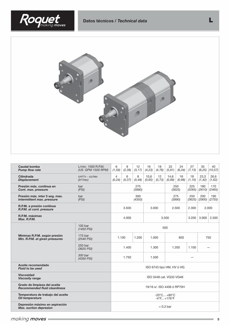
Datos técnicos / Technical data L
Caudal bombaPump flow rate
CilindradaDisplacement
Presión máx. continua enCont. max. pressure
Presión máx. inter 5 seg. max.Intermittent max. pressure
R.P.M. a presión continuaR.P.M. at cont. pressure
R.P.M. máximasMax. R.P.M.
Mínimas R.P.M. según presiónMin. R.P.M. at given pressures
Aceite recomendadoFluid to be used
ViscosidadViscosity range
Grado de limpieza del aceiteRecommended fluid cleanliness
Temperatura de trabajo del aceiteOil temperature
Depresión máximo en aspiraciónMax. suction depresion
L/min. 1500 R.P.M.(US. GPM 1500 RPM)
cm3/v - cc/rev(in3/rev)
bar(PSI)
bar(PSI)
100 bar(1450 PSI)
175 bar(2540 PSI)
250 bar(3625 PSI)
300 bar(4350 PSI)
6(1,59)
4(0,24)
18(4,76)
12(0,73)
9(2,38)
6(0,37)
ISO 6743 tipo HM, HV ó HG
ISO 3448 cat. VG32-VG46
19/16 s/. ISO 4406 ó RP70H
-20°C... +80°C-4°F... +176°F
< 0,3 bar
12(3,17)
8(0,49)
275(3990)
300(4350)
250(3625)
275(3990)
16(4,23)
10,6(0,65)
22(5,81)
14,6(0,89)
24(6,34)
16(0,98)
40(10,57)
26,6(1,62)
170(2465)
190(2755)
35(9,25)
23,3(1,42)
180(2610)
200(2900)
27(7,13)
18(1,10)
225(3265)
250(3625)
2.300
3.200
1.100
3.000 2.500
3.500
4.000
1.400
1.750
1.300
1.500
1.200
1.100 1.200
3.500
500
3.000
1.000 850 750
—
—
2.500 2.000
6
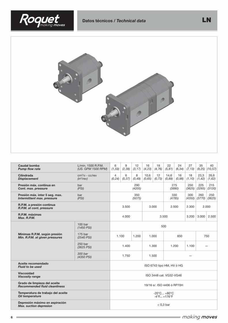
Datos técnicos / Technical data LN
Caudal bombaPump flow rate
CilindradaDisplacement
Presión máx. continua enCont. max. pressure
Presión máx. inter 5 seg. max.Intermittent max. pressure
R.P.M. a presión continuaR.P.M. at cont. pressure
R.P.M. máximasMax. R.P.M.
Mínimas R.P.M. según presiónMin. R.P.M. at given pressures
Aceite recomendadoFluid to be used
ViscosidadViscosity range
Grado de limpieza del aceiteRecommended fluid cleanliness
Temperatura de trabajo del aceiteOil temperature
Depresión máximo en aspiraciónMax. suction depresion
L/min. 1500 R.P.M.(US. GPM 1500 RPM)
cm3/v - cc/rev(in3/rev)
bar(PSI)
bar(PSI)
100 bar(1450 PSI)
175 bar(2540 PSI)
250 bar(3625 PSI)
300 bar(4350 PSI)
6(1,59)
4(0,24)
18(4,76)
12(0,73)
9(2,38)
6(0,37)
ISO 6743 tipo HM, HV ó HG
ISO 3448 cat. VG32-VG46
19/16 s/. ISO 4406 ó RP70H
-20°C... +80°C-4°F... +176°F
< 0,3 bar
12(3,17)
8(0,49)
290(4205)
350(5075)
275(3990)
330(4785)
16(4,23)
10,6(0,65)
22(5,81)
14,6(0,89)
24(6,34)
16(0,98)
40(10,57)
26,6(1,62)
215(3120)
250(3625)
35(9,25)
23,3(1,42)
225(3265)
260(3770)
27(7,13)
18(1,10)
250(3625)
300(4350)
2.300
3.200
1.100
3.000 2.500
3.500
4.000
1.400
1.750
1.300
1.500
1.200
1.100 1.200
3.500
500
3.000
1.000 850 750
—
—
2.500 2.000
7
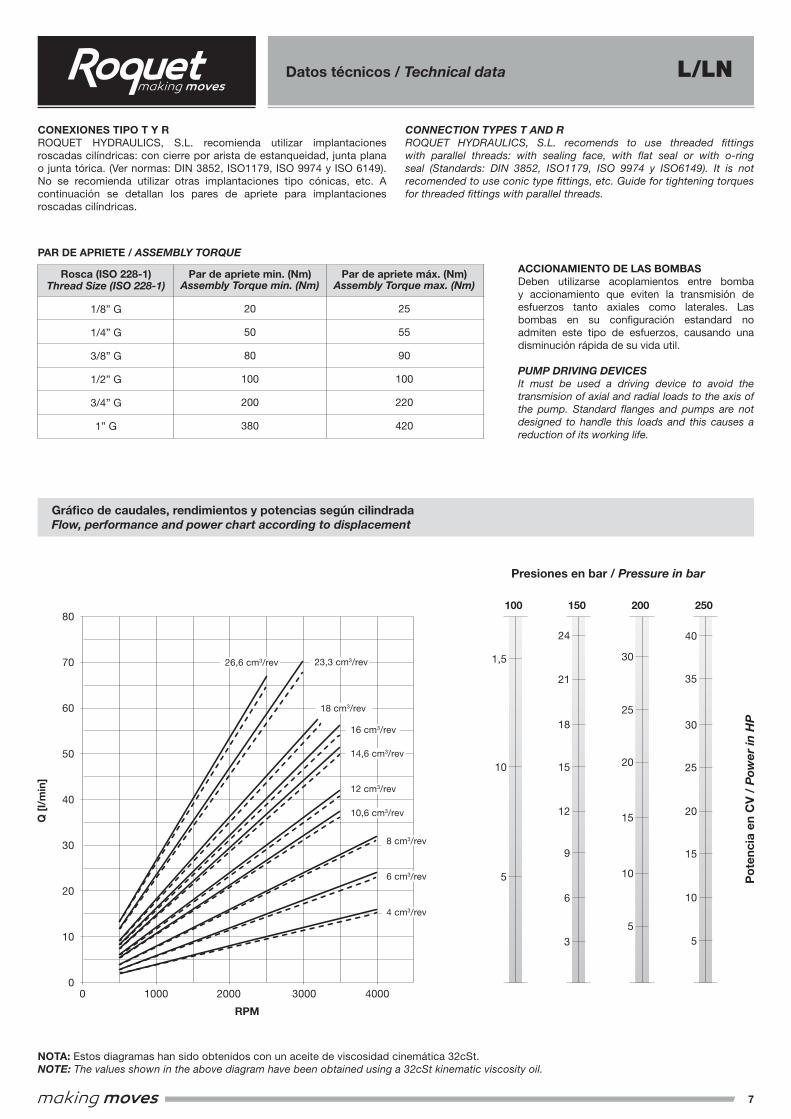
Datos técnicos / Technical data
NOTA: Estos diagramas han sido obtenidos con un aceite de viscosidad cinemática 32cSt.NOTE: The values shown in the above diagram have been obtained using a 32cSt kinematic viscosity oil.
Gráfico de caudales, rendimientos y potencias según cilindradaFlow, performance and power chart according to displacement
Presiones en bar / Pressure in bar
Po
tenc
ia e
n C
V /
Pow
er in
HP
Q [
l/m
in]
RPM
80
70
60
50
40
30
20
10
00 1000 2000 3000 4000
10,6 cm3/rev
14,6 cm3/rev
12 cm3/rev
16 cm3/rev
18 cm3/rev
23,3 cm3/rev26,6 cm3/rev
4 cm3/rev
6 cm3/rev
8 cm3/rev
100
5
10
1,5
150
6
3
15
21
18
24
12
9
200
5
15
10
20
30
25
250
10
5
15
20
25
40
35
30
CONEXIONES TIPO T Y RROQUET HYDRAULICS, S.L. recomienda utilizar implantaciones roscadas cilíndricas: con cierre por arista de estanqueidad, junta plana o junta tórica. (Ver normas: DIN 3852, ISO1179, ISO 9974 y ISO 6149). No se recomienda utilizar otras implantaciones tipo cónicas, etc. A continuación se detallan los pares de apriete para implantaciones roscadas cilíndricas.
CONNECTION TYPES T AND RROQUET HYDRAULICS, S.L. recomends to use threaded fittings with parallel threads: with sealing face, with flat seal or with o-ring seal (Standards: DIN 3852, ISO1179, ISO 9974 y ISO6149). It is not recomended to use conic type fittings, etc. Guide for tightening torques for threaded fittings with parallel threads.
ACCIONAMIENTO DE LAS BOMBASDeben utilizarse acoplamientos entre bomba y accionamiento que eviten la transmisión de esfuerzos tanto axiales como laterales. Las bombas en su configuración estandard no admiten este tipo de esfuerzos, causando una disminución rápida de su vida util.
PUMP DRIVING DEVICESIt must be used a driving device to avoid the transmision of axial and radial loads to the axis of the pump. Standard flanges and pumps are not designed to handle this loads and this causes a reduction of its working life.
PAR DE APRIETE / ASSEMBLY TORQUE
Rosca (ISO 228-1)Thread Size (ISO 228-1)
1/8” G
1/4” G
3/8” G
1/2” G
3/4” G
1” G
Par de apriete min. (Nm)Assembly Torque min. (Nm)
20
50
80
100
200
380
Par de apriete máx. (Nm)Assembly Torque max. (Nm)
25
55
90
100
220
420
L/LN
8
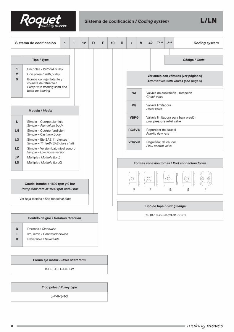
Sistema de codificación / Coding system
VA
V@
VBP@
RC@V@
VC@V@
Sistema de codificación Coding system1 L 12 D E 10 R / V 42 T*** -***
Derecha / Clockwise
Izquierda / Counterclockwise
Reversible / Reversible
Sentido de giro / Rotation direction
D
I
R
Ver hoja técnica / See technical data
Caudal bomba a 1500 rpm y 0 bar
Pump flow rate at 1500 rpm and 0 bar
Formas conexión tomas / Port connection forms
09-10-19-22-23-29-31-55-61
B-C-E-G-H-J-R-T-W
Forma eje motriz / Drive shaft form
Tipo de tapa / Fixing flange
L-P-R-S-T-X
Tipo polea / Pulley type
Sin polea / Without pulley
Con polea / With pulley
Bomba con eje flotante y cojinete de refuerzo / Pump with floating shaft and back-up bearing
Tipo / Type Código / Code
1
2
5
Válvula de aspiración - retenciónCheck valve
Válvula limitadoraRelief valve
Válvula limitadora para baja presiónLow pressure relief valve
Repartidor de caudalPriority flow rate
Regulador de caudalFlow control valve
Variantes con válvulas (ver página 9)
Alternatives with valves (see page 9)
Simple – Cuerpo aluminioSimple – Aluminium body
Simple – Cuerpo fundiciónSimple – Cast iron body
Simple – Eje SAE 11 dientesSimple – 11 teeth SAE drive shaft
Simple – Versión bajo nivel sonoroSimple – Low noise version
Múltiple / Multiple (L+L)
Múltiple / Multiple (L+L0)
Modelo / Model
L
LN
LG
LZ
LM
LS
TFR B S
L/LN
9
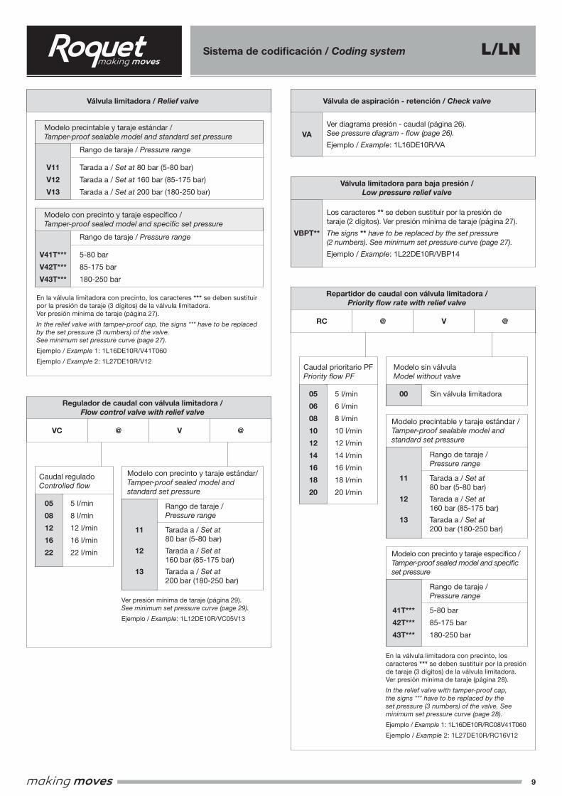
Sistema de codificación / Coding system
VBPT**
VA
Los caracteres ** se deben sustituir por la presión de taraje (2 dígitos). Ver presión mínima de taraje (página 27).
The signs ** have to be replaced by the set pressure(2 numbers). See minimum set pressure curve (page 27).
Ejemplo / Example: 1L22DE10R/VBP14
Ver diagrama presión - caudal (página 26).See pressure diagram - flow (page 26).
Ejemplo / Example: 1L16DE10R/VA
RC
VC
@
@
V
V
@
@
En la válvula limitadora con precinto, los caracteres *** se deben sustituir por la presión de taraje (3 dígitos) de la válvula limitadora.Ver presión mínima de taraje (página 27).
In the relief valve with tamper-proof cap, the signs *** have to be replaced by the set pressure (3 numbers) of the valve.See minimum set pressure curve (page 27).
Ejemplo / Example 1: 1L16DE10R/V41T060
Ejemplo / Example 2: 1L27DE10R/V12
En la válvula limitadora con precinto, los caracteres *** se deben sustituir por la presión de taraje (3 dígitos) de la válvula limitadora.Ver presión mínima de taraje (página 28).
In the relief valve with tamper-proof cap, the signs *** have to be replaced by the set pressure (3 numbers) of the valve. See minimum set pressure curve (page 28).
Ejemplo / Example 1: 1L16DE10R/RC08V41T060
Ejemplo / Example 2: 1L27DE10R/RC16V12
Ver presión mínima de taraje (página 29).See minimum set pressure curve (page 29).
Ejemplo / Example: 1L12DE10R/VC05V13
V11
V12
V13
05
06
08
10
12
14
16
18
2005
08
12
16
22
00
11
12
13
41T***
42T***
43T***
V41T***
V42T***
V43T***
Rango de taraje / Pressure range
Tarada a / Set at 80 bar (5-80 bar)
Tarada a / Set at 160 bar (85-175 bar)
Tarada a / Set at 200 bar (180-250 bar)
5 l/min
6 l/min
8 l/min
10 l/min
12 l/min
14 l/min
16 l/min
18 l/min
20 l/min5 l/min
8 l/min
12 l/min
16 l/min
22 l/min
Sin válvula limitadora
Tarada a / Set at80 bar (5-80 bar)
Tarada a / Set at160 bar (85-175 bar)
Tarada a / Set at200 bar (180-250 bar)
5-80 bar
85-175 bar
180-250 bar
Rango de taraje / Pressure range
Rango de taraje / Pressure range
Caudal prioritario PFPriority flow PF
Caudal reguladoControlled flow
Modelo sin válvulaModel without valve
Modelo precintable y taraje estándar /Tamper-proof sealable model and standard set pressure
Modelo con precinto y taraje específico /Tamper-proof sealed model and specific set pressure
Rango de taraje / Pressure range
5-80 bar
85-175 bar
180-250 bar
Variantes con válvulas / Alternatives with valves
Variantes con válvulas / Alternatives with valvesVariantes con válvulas / Alternatives with valves
Válvula limitadora para baja presión /Low pressure relief valve
Válvula de aspiración - retención / Check valve
Repartidor de caudal con válvula limitadora /Priority flow rate with relief valve
Regulador de caudal con válvula limitadora /Flow control valve with relief valve
Válvula limitadora / Relief valve
Modelo precintable y taraje estándar /Tamper-proof sealable model and standard set pressure
Modelo con precinto y taraje específico /Tamper-proof sealed model and specific set pressure
11
12
13
Tarada a / Set at80 bar (5-80 bar)
Tarada a / Set at160 bar (85-175 bar)
Tarada a / Set at200 bar (180-250 bar)
Rango de taraje / Pressure range
Modelo con precinto y taraje estándar/Tamper-proof sealed model and standard set pressure
L/LN
10
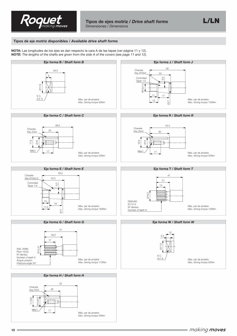
Tipos de ejes motriz / Drive shaft formsDimensiones / Dimensions
Tipos de eje motriz disponibles / Available drive shaft forms
Eje forma B / Shaft form B
NOTA: Las longitudes de los ejes se dan respecto la cara A de las tapas (ver página 11 y 12).NOTE: The lengths of the shafts are given from the side A of the covers (see page 11 and 12).
Eje forma J / Shaft form J
Eje forma C / Shaft form C Eje forma R / Shaft form R
Eje forma E / Shaft form E Eje forma T / Shaft form T
Eje forma G / Shaft form G Eje forma W / Shaft form W
Eje forma H / Shaft form H
Eje tipo C / Shaft form C
Eje tipo E / Shaft form E
Eje tipo G / Shaft form G
Eje tipo H / Shaft form H
Eje tipo J / Shaft form J
Eje tipo R / Shaft form R
Eje tipo T / Shaft form T
Eje tipo W / Shaft form W
Eje tipo B / Shaft form B
29,5
56
48,5
55,5
58,5
51
41
12
52
25
28,5
17
34,5
1911,5
10
25
8
33
17
13
11
30
21
14
6,5
17,8
16,5
15
17
15
,875
17,5
05
15,3
1
17
16
17,8
17,6
E.C. A.F. 8
E.C. A.F. 8
9,5
9,5
16,6
Max Par de arrastreMax. driving torque 65Nm
Max Par de arrastreMax. driving torque 55Nm
Max Par de arrastreMax. driving torque 160Nm
Max Par de arrastreMax. driving torque 110Nm
Max Par de arrastreMax. driving torque 55Nm
Max Par de arrastreMax. driving torque 155Nm
Max Par de arrastreMax. driving torque 55Nm
Max Par de arrastreMax. driving torque 130Nm
Max Par de arrastreMax. driving torque 65Nm
Conicidad Taper 1:8
Conicidad Taper 1:5
17
17
17
M12x
1.5
M6x1
M6x1
M6x1
DIN5482Ø17x14
Nº dientesNumber of teeth 9
SAE J498bPitch 16/32Nº dientes
Number of teeth 9Ángulo presión
Pressure angle 30°
Chaveta Key 22x4
Chaveta Key 22x4
Chaveta Key 25x4
Chaveta Key Ø16x3
Chaveta Key Ø16x3.2
Eje tipo C / Shaft form C
Eje tipo E / Shaft form E
Eje tipo G / Shaft form G
Eje tipo H / Shaft form H
Eje tipo J / Shaft form J
Eje tipo R / Shaft form R
Eje tipo T / Shaft form T
Eje tipo W / Shaft form W
Eje tipo B / Shaft form B
29,5
56
48,5
55,5
58,5
51
41
12
52
25
28,5
17
34,5
1911,5
10
25
8
33
17
13
11
30
21
14
6,5
17,8
16,5
15
17
15
,875
17,5
05
15,3
1
17
16
17,8
17,6
E.C. A.F. 8
E.C. A.F. 8
9,5
9,5
16,6
Max Par de arrastreMax. driving torque 65Nm
Max Par de arrastreMax. driving torque 55Nm
Max Par de arrastreMax. driving torque 160Nm
Max Par de arrastreMax. driving torque 110Nm
Max Par de arrastreMax. driving torque 55Nm
Max Par de arrastreMax. driving torque 155Nm
Max Par de arrastreMax. driving torque 55Nm
Max Par de arrastreMax. driving torque 130Nm
Max Par de arrastreMax. driving torque 65Nm
Conicidad Taper 1:8
Conicidad Taper 1:5
17
17
17M1
2x1.5
M6x1
M6x1
M6x1
DIN5482Ø17x14
Nº dientesNumber of teeth 9
SAE J498bPitch 16/32Nº dientes
Number of teeth 9Ángulo presión
Pressure angle 30°
Chaveta Key 22x4
Chaveta Key 22x4
Chaveta Key 25x4
Chaveta Key Ø16x3
Chaveta Key Ø16x3.2
Eje tipo C / Shaft form C
Eje tipo E / Shaft form E
Eje tipo G / Shaft form G
Eje tipo H / Shaft form H
Eje tipo J / Shaft form J
Eje tipo R / Shaft form R
Eje tipo T / Shaft form T
Eje tipo W / Shaft form W
Eje tipo B / Shaft form B
29,5
56
48,5
55,5
58,5
51
41
12
52
25
28,5
17
34,5
1911,5
10
25
8
33
17
13
11
30
21
14
6,5
17,8
16,5
15
17
15
,875
17,5
05
15,3
1
17
16
17,8
17,6
E.C. A.F. 8
E.C. A.F. 8
9,5
9,5
16,6
Max Par de arrastreMax. driving torque 65Nm
Max Par de arrastreMax. driving torque 55Nm
Max Par de arrastreMax. driving torque 160Nm
Max Par de arrastreMax. driving torque 110Nm
Max Par de arrastreMax. driving torque 55Nm
Max Par de arrastreMax. driving torque 155Nm
Max Par de arrastreMax. driving torque 55Nm
Max Par de arrastreMax. driving torque 130Nm
Max Par de arrastreMax. driving torque 65Nm
Conicidad Taper 1:8
Conicidad Taper 1:5
17
17
17
M12x
1.5
M6x1
M6x1
M6x1
DIN5482Ø17x14
Nº dientesNumber of teeth 9
SAE J498bPitch 16/32Nº dientes
Number of teeth 9Ángulo presión
Pressure angle 30°
Chaveta Key 22x4
Chaveta Key 22x4
Chaveta Key 25x4
Chaveta Key Ø16x3
Chaveta Key Ø16x3.2
Eje tipo C / Shaft form C
Eje tipo E / Shaft form E
Eje tipo G / Shaft form G
Eje tipo H / Shaft form H
Eje tipo J / Shaft form J
Eje tipo R / Shaft form R
Eje tipo T / Shaft form T
Eje tipo W / Shaft form W
Eje tipo B / Shaft form B
29,5
56
48,5
55,5
58,5
51
41
12
52
25
28,5
17
34,5
1911,5
10
25
8
33
17
13
11
30
21
14
6,5
17,8
16,5
15
17
15
,875
17,5
05
15,3
1
17
16
17,8
17,6
E.C. A.F. 8
E.C. A.F. 8
9,5
9,5
16,6
Max Par de arrastreMax. driving torque 65Nm
Max Par de arrastreMax. driving torque 55Nm
Max Par de arrastreMax. driving torque 160Nm
Max Par de arrastreMax. driving torque 110Nm
Max Par de arrastreMax. driving torque 55Nm
Max Par de arrastreMax. driving torque 155Nm
Max Par de arrastreMax. driving torque 55Nm
Max Par de arrastreMax. driving torque 130Nm
Max Par de arrastreMax. driving torque 65Nm
Conicidad Taper 1:8
Conicidad Taper 1:5
17
17
17
M12x
1.5
M6x1
M6x1
M6x1
DIN5482Ø17x14
Nº dientesNumber of teeth 9
SAE J498bPitch 16/32Nº dientes
Number of teeth 9Ángulo presión
Pressure angle 30°
Chaveta Key 22x4
Chaveta Key 22x4
Chaveta Key 25x4
Chaveta Key Ø16x3
Chaveta Key Ø16x3.2
L/LN
29,5
48,5
58,5
55,5
M6x1 M6x1
56
33
25
34,5
30
41
51
25
17
52
126,5
21
28,5
14
17
11
10
17
1911,5
17 17
13
Ø17
,8
Ø17
Ø17
17,6
16,6
Ø16
,5
Ø15
,31
Ø17
,8
Ø15
,875
Ø16
Ø15
9,5
9,5
8
E.C.A.F. 8
ChavetaKey Ø16x3
ChavetaKey 22x4
ChavetaKey Ø16x3,2
ChavetaKey 22x4
ChavetaKey 25x4
Máx. par de arrastreMax. driving torque 65Nm
Máx. par de arrastreMax. driving torque 55Nm
Máx. par de arrastreMax. driving torque 160Nm
Máx. par de arrastreMax. driving torque 110Nm
Máx. par de arrastreMax. driving torque 55Nm
Máx. par de arrastreMax. driving torque 55Nm
Máx. par de arrastreMax. driving torque 130Nm
Máx. par de arrastreMax. driving torque 65Nm
DIN5482Ø17x14Nº dientesNumber of teeth 9
SAE J498bPitch 16/32Nº dientesNumber of teeth 9Ángulo presiónPressure angle 30º
Máx. par de arrastreMax. driving torque 155Nm
ConicidadTaper 1:5
ConicidadTaper 1:8
M12
x1,5
E.C.A.F. 8
M6x1
17,5
05
11
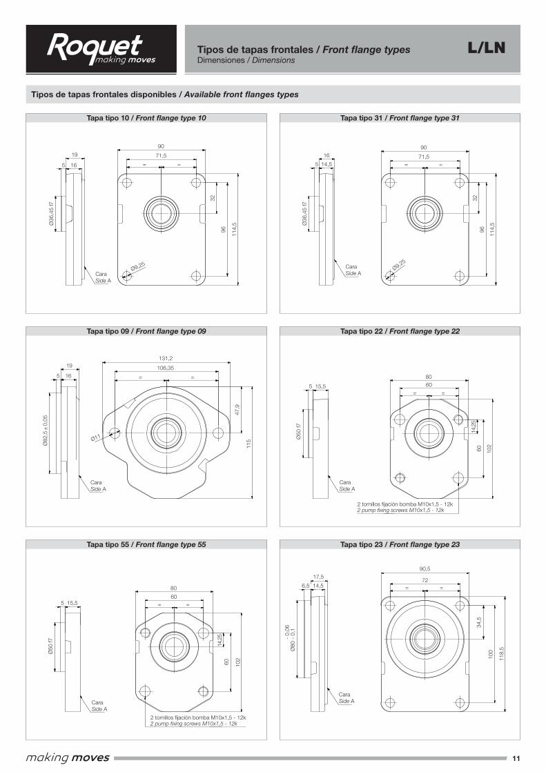
Tipos de tapas frontales disponibles / Available front flanges types
Tapa tipo 10 / Front flange type 10 Tapa tipo 31 / Front flange type 31
Tapa tipo 09 / Front flange type 09
Tapa tipo 55 / Front flange type 55
Tapa tipo 22 / Front flange type 22
Tapa tipo 23 / Front flange type 23
Tipos de tapas frontales / Front flange typesDimensiones / Dimensions
115
106,35
= =
11
47,9
82,5
0,05
19
165
36
,45
f7
5 16
19 71,5
= =
32
96 114,
5
90
9,25
131,2
60= =
60
14,2
5
102
80
52
-0,
060,
03-
7,2 14,8
60= =
6014
,25
102
7 15
52
-0,
060,
03-
7 15
52
-0,
060,
03-
34,5
100
72
= =
90,5
118,5
80
-0,
10,
06-
6,5 14,5
17,5
50
f7
5 15,560
= =
14,2
5
60 102
80
60
= =
102
14,2
560
80
15,55
50
f7
36
,45
f7
5 14,5
16 71,5
= =
9,25
32
96 114,5
90
60
= =
6014
,25
102
80
Cara Side A
Cara Side A
Cara Side A Cara
Side A
Cara Side A
Cara Side A Cara
Side A
Cara Side A
Cara Side A
Tapa frontal tipo 09/Front flange type 09
Tapa frontal tipo 10/Front flange type 10
Tapa frontal tipo 19/Front flange type 19
Tapa frontal tipo 22/Front flange type 22
Tapa frontal tipo 23/Front flange type 23
Tapa frontal tipo 29/Front flange type 29
Tapa frontal tipo 31/Front flange type 31
Tapa frontal tipo 55/Front flange type 55
Tapa frontal tipo 61/Front flange type 61
47,8
0,05
3,2
2
47,8
0,05
47,8
0,05
3,2
23,2
2
EJEMPLO: combinación de un eje tipo E con una tapa tipo 10.EXAMPLE: combination of a E type shaft with a 10 type front flange.
39,5
28
16,5
19
9,5
17
36
,45
f7
M12x
1.25
Chaveta Key 16x3,2
ConicidadTaper 1:8
5
2 tornillos fijación bomba M10x1,5 - 12k2 pump fixing screws M10x1,5 - 12k
2 tornillos fijación bomba M10x1,5 - 12k2 pump fixing screws M10x1,5 - 12k
2 tornillos fijación bomba M10x1,5 - 12k2 pump fixing screws M10x1,5 - 12k
2 tornillos fijación bomba M10x1,5 - 12k2 pump fixing screws M10x1,5 - 12k4 tornillos fijación bomba M10x1,5 - 12k
4 pump fixing screws M10x1,5 - 12k
115
106,35
= =
11
47,9
82,5
0,05
19
165
36
,45
f7
5 16
19 71,5
= =
32
96 114,
5
90
9,25
131,2
60= =
60
14,2
5
102
80
52
-0,
060,
03-
7,2 14,8
60= =
6014
,25
102
7 15
52
-0,
060,
03-
7 15
52
-0,
060,
03-
34,5
100
72
= =
90,5118
,5
80
-0,
10,
06-
6,5 14,5
17,5
50
f7
5 15,560
= =
14,2
5
60 102
80
60
= =
102
14,2
560
80
15,55
50
f7
36
,45
f7
5 14,5
16 71,5
= =
9,25
32
96 114,5
90
60
= =
6014
,25
102
80
Cara Side A
Cara Side A
Cara Side A Cara
Side A
Cara Side A
Cara Side A Cara
Side A
Cara Side A
Cara Side A
Tapa frontal tipo 09/Front flange type 09
Tapa frontal tipo 10/Front flange type 10
Tapa frontal tipo 19/Front flange type 19
Tapa frontal tipo 22/Front flange type 22
Tapa frontal tipo 23/Front flange type 23
Tapa frontal tipo 29/Front flange type 29
Tapa frontal tipo 31/Front flange type 31
Tapa frontal tipo 55/Front flange type 55
Tapa frontal tipo 61/Front flange type 61
47,8
0,05
3,2
2
47,8
0,05
47,8
0,05
3,2
23,2
2
EJEMPLO: combinación de un eje tipo E con una tapa tipo 10.EXAMPLE: combination of a E type shaft with a 10 type front flange.
39,5
28
16,5
19
9,5
17
36
,45
f7
M12x
1.25
Chaveta Key 16x3,2
ConicidadTaper 1:8
5
2 tornillos fijación bomba M10x1,5 - 12k2 pump fixing screws M10x1,5 - 12k
2 tornillos fijación bomba M10x1,5 - 12k2 pump fixing screws M10x1,5 - 12k
2 tornillos fijación bomba M10x1,5 - 12k2 pump fixing screws M10x1,5 - 12k
2 tornillos fijación bomba M10x1,5 - 12k2 pump fixing screws M10x1,5 - 12k4 tornillos fijación bomba M10x1,5 - 12k
4 pump fixing screws M10x1,5 - 12k
115
106,35
= =
11
47,9
82,5
0,05
19
165
36
,45
f7
5 16
19 71,5
= =
32
96 114,
5
90
9,25
131,2
60= =
60
14,2
5
102
80
52
-0,
060,
03-
7,2 14,8
60= =
6014
,25
102
7 15
52
-0,
060,
03-
7 15
52
-0,
060,
03-
34,5
100
72
= =
90,5
118,5
80
-0,
10,
06-
6,5 14,5
17,5
50
f7
5 15,560
= =
14,2
5
60 102
80
60
= =
102
14,2
560
80
15,55
50
f7
36
,45
f7
5 14,5
16 71,5
= =
9,25
32
96 114,5
90
60
= =
6014
,25
102
80
Cara Side A
Cara Side A
Cara Side A Cara
Side A
Cara Side A
Cara Side A Cara
Side A
Cara Side A
Cara Side A
Tapa frontal tipo 09/Front flange type 09
Tapa frontal tipo 10/Front flange type 10
Tapa frontal tipo 19/Front flange type 19
Tapa frontal tipo 22/Front flange type 22
Tapa frontal tipo 23/Front flange type 23
Tapa frontal tipo 29/Front flange type 29
Tapa frontal tipo 31/Front flange type 31
Tapa frontal tipo 55/Front flange type 55
Tapa frontal tipo 61/Front flange type 61
47,8
0,05
3,2
2
47,8
0,05
47,8
0,05
3,2
23,2
2
EJEMPLO: combinación de un eje tipo E con una tapa tipo 10.EXAMPLE: combination of a E type shaft with a 10 type front flange.
39,5
28
16,5
19
9,5
17
36
,45
f7
M12x
1.25
Chaveta Key 16x3,2
ConicidadTaper 1:8
5
2 tornillos fijación bomba M10x1,5 - 12k2 pump fixing screws M10x1,5 - 12k
2 tornillos fijación bomba M10x1,5 - 12k2 pump fixing screws M10x1,5 - 12k
2 tornillos fijación bomba M10x1,5 - 12k2 pump fixing screws M10x1,5 - 12k
2 tornillos fijación bomba M10x1,5 - 12k2 pump fixing screws M10x1,5 - 12k4 tornillos fijación bomba M10x1,5 - 12k
4 pump fixing screws M10x1,5 - 12k
115
106,35
= =
11
47,9
82,5
0,05
19
165
36
,45
f7
5 16
19 71,5
= =
32
96 114,
5
90
9,25
131,2
60= =
60
14,2
5
102
80
52
-0,
060,
03-
7,2 14,8
60= =
6014
,25
102
7 15
52
-0,
060,
03-
7 15
52
-0,
060,
03-
34,5
100
72
= =
90,5
118,5
80
-0,
10,
06-
6,5 14,5
17,5
50
f75 15,5
60
= =
14,2
5
60 102
80
60
= =
102
14,2
560
80
15,55
50
f7
36
,45
f7
5 14,5
16 71,5
= =
9,25
32
96 114,5
90
60
= =
6014
,25
102
80
Cara Side A
Cara Side A
Cara Side A Cara
Side A
Cara Side A
Cara Side A Cara
Side A
Cara Side A
Cara Side A
Tapa frontal tipo 09/Front flange type 09
Tapa frontal tipo 10/Front flange type 10
Tapa frontal tipo 19/Front flange type 19
Tapa frontal tipo 22/Front flange type 22
Tapa frontal tipo 23/Front flange type 23
Tapa frontal tipo 29/Front flange type 29
Tapa frontal tipo 31/Front flange type 31
Tapa frontal tipo 55/Front flange type 55
Tapa frontal tipo 61/Front flange type 61
47,8
0,05
3,2
2
47,8
0,05
47,8
0,05
3,2
23,2
2
EJEMPLO: combinación de un eje tipo E con una tapa tipo 10.EXAMPLE: combination of a E type shaft with a 10 type front flange.
39,5
28
16,5
19
9,5
17
36
,45
f7
M12x
1.25
Chaveta Key 16x3,2
ConicidadTaper 1:8
5
2 tornillos fijación bomba M10x1,5 - 12k2 pump fixing screws M10x1,5 - 12k
2 tornillos fijación bomba M10x1,5 - 12k2 pump fixing screws M10x1,5 - 12k
2 tornillos fijación bomba M10x1,5 - 12k2 pump fixing screws M10x1,5 - 12k
2 tornillos fijación bomba M10x1,5 - 12k2 pump fixing screws M10x1,5 - 12k4 tornillos fijación bomba M10x1,5 - 12k
4 pump fixing screws M10x1,5 - 12k
115
106,35
= =
11
47,9
82,5
0,05
19
165
36
,45
f7
5 16
19 71,5
= =
32
96 114,
5
90
9,25
131,2
60= =
60
14,2
5
102
80
52
-0,
060,
03-
7,2 14,8
60= =
6014
,25
102
7 15
52
-0,
060,
03-
7 15
52
-0,
060,
03-
34,5
100
72
= =
90,5
118,5
80
-0,
10,
06-
6,5 14,5
17,5
50
f7
5 15,560
= =
14,2
5
60 102
80
60
= =
102
14,2
560
80
15,55
50
f7
36
,45
f7
5 14,5
16 71,5
= =
9,25
32
96 114,5
90
60
= =
6014
,25
102
80
Cara Side A
Cara Side A
Cara Side A Cara
Side A
Cara Side A
Cara Side A Cara
Side A
Cara Side A
Cara Side A
Tapa frontal tipo 09/Front flange type 09
Tapa frontal tipo 10/Front flange type 10
Tapa frontal tipo 19/Front flange type 19
Tapa frontal tipo 22/Front flange type 22
Tapa frontal tipo 23/Front flange type 23
Tapa frontal tipo 29/Front flange type 29
Tapa frontal tipo 31/Front flange type 31
Tapa frontal tipo 55/Front flange type 55
Tapa frontal tipo 61/Front flange type 61
47,8
0,05
3,2
2
47,8
0,05
47,8
0,05
3,2
23,2
2
EJEMPLO: combinación de un eje tipo E con una tapa tipo 10.EXAMPLE: combination of a E type shaft with a 10 type front flange.
39,5
28
16,5
19
9,5
17
36
,45
f7
M12x
1.25
Chaveta Key 16x3,2
ConicidadTaper 1:8
5
2 tornillos fijación bomba M10x1,5 - 12k2 pump fixing screws M10x1,5 - 12k
2 tornillos fijación bomba M10x1,5 - 12k2 pump fixing screws M10x1,5 - 12k
2 tornillos fijación bomba M10x1,5 - 12k2 pump fixing screws M10x1,5 - 12k
2 tornillos fijación bomba M10x1,5 - 12k2 pump fixing screws M10x1,5 - 12k4 tornillos fijación bomba M10x1,5 - 12k
4 pump fixing screws M10x1,5 - 12k
L/LN
CaraSide A
CaraSide A
CaraSide A
CaraSide A
CaraSide A
2 tornillos fijación bomba M10x1,5 - 12k2 pump fixing screws M10x1,5 - 12k
2 tornillos fijación bomba M10x1,5 - 12k2 pump fixing screws M10x1,5 - 12k
Ø36
,45
f7Ø
82,5
± 0
,05
Ø36
,45
f7Ø
50 f7
Ø50
f7
32
47,9
3234
,514
,25
14,2
596 96
100
60
6011
4,5
115
114,
5
118,
5
102
102
16
16
14,5
15,5
15,5
Ø9,25
Ø11
Ø9,25
90
131,2
106,35
90
90,5
80
80
71,5 71,5
72
60
60
=
=
=
=
=
=
=
=
=
=
=
=
19
19
16
5
5
5
5
5
CaraSide A
14,5
17,5
6,5
-
0,06
Ø80
- 0
,1
12
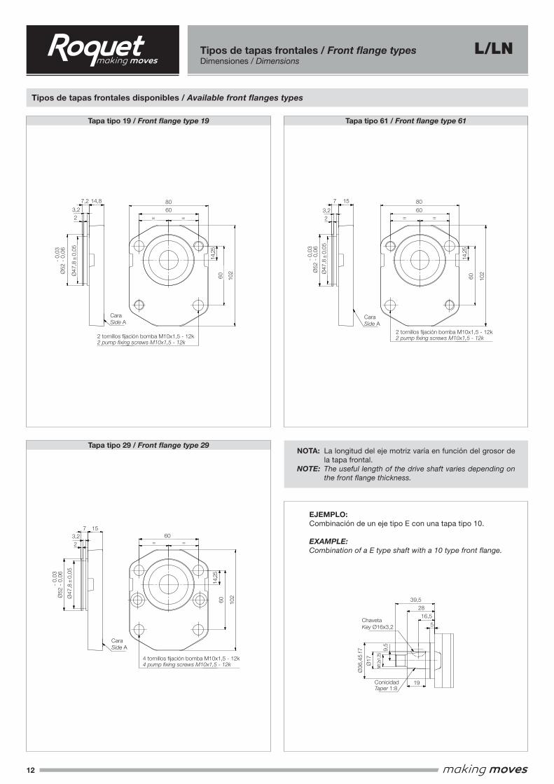
Tipos de tapas frontales disponibles / Available front flanges types
Tapa tipo 19 / Front flange type 19
Tapa tipo 29 / Front flange type 29
Tapa tipo 61 / Front flange type 61
Tipos de tapas frontales / Front flange typesDimensiones / Dimensions
L/LN
NOTA: La longitud del eje motriz varía en función del grosor de la tapa frontal.
NOTE: The useful length of the drive shaft varies depending on the front flange thickness.
EJEMPLO:Combinación de un eje tipo E con una tapa tipo 10.
EXAMPLE:Combination of a E type shaft with a 10 type front flange.
115
106,35
= =
11
47,9
82,5
0,05
19
165
36
,45
f7
5 16
19 71,5
= =
32
96 114,
5
90
9,25
131,2
60= =
60
14,2
5
102
80
52
-0,
060,
03-
7,2 14,8
60= =
6014
,25
102
7 15
52
-0,
060,
03-
7 15
52
-0,
060,
03-
34,5
100
72
= =
90,5
118,5
80
-0,
10,
06-
6,5 14,5
17,5
50
f7
5 15,560
= =
14,2
5
60 102
80
60
= =
102
14,2
560
80
15,55
50
f7
36
,45
f7
5 14,5
16 71,5
= =
9,25
32
96 114,5
90
60
= =
6014
,25
102
80
Cara Side A
Cara Side A
Cara Side A Cara
Side A
Cara Side A
Cara Side A Cara
Side A
Cara Side A
Cara Side A
Tapa frontal tipo 09/Front flange type 09
Tapa frontal tipo 10/Front flange type 10
Tapa frontal tipo 19/Front flange type 19
Tapa frontal tipo 22/Front flange type 22
Tapa frontal tipo 23/Front flange type 23
Tapa frontal tipo 29/Front flange type 29
Tapa frontal tipo 31/Front flange type 31
Tapa frontal tipo 55/Front flange type 55
Tapa frontal tipo 61/Front flange type 61
47,8
0,05
3,2
2
47,8
0,05
47,8
0,05
3,2
23,2
2
EJEMPLO: combinación de un eje tipo E con una tapa tipo 10.EXAMPLE: combination of a E type shaft with a 10 type front flange.
39,5
28
16,5
19
9,5
17
36
,45
f7
M12x
1.25
Chaveta Key 16x3,2
ConicidadTaper 1:8
5
2 tornillos fijación bomba M10x1,5 - 12k2 pump fixing screws M10x1,5 - 12k
2 tornillos fijación bomba M10x1,5 - 12k2 pump fixing screws M10x1,5 - 12k
2 tornillos fijación bomba M10x1,5 - 12k2 pump fixing screws M10x1,5 - 12k
2 tornillos fijación bomba M10x1,5 - 12k2 pump fixing screws M10x1,5 - 12k4 tornillos fijación bomba M10x1,5 - 12k
4 pump fixing screws M10x1,5 - 12k
Ø36
,45
f7
ChavetaKey Ø16x3,2
ConicidadTaper 1:8
39,5
16,5
28
19
5
M12
x1,2
5
Ø17
9,5
60 60
60
102
102
102
80 8060 60
60
= =
=
= =
=
CaraSide A
CaraSide A
CaraSide A
14,8 15
15
7,2 7
7
3,2 3,2
3,2
2 2
2
-
0,03
Ø52
- 0
,06
-
0,03
Ø52
- 0
,06
-
0,03
Ø52
- 0
,06
2 tornillos fijación bomba M10x1,5 - 12k2 pump fixing screws M10x1,5 - 12k
4 tornillos fijación bomba M10x1,5 - 12k4 pump fixing screws M10x1,5 - 12k
2 tornillos fijación bomba M10x1,5 - 12k2 pump fixing screws M10x1,5 - 12k
Ø47
,8 ±
0,0
5
Ø47
,8 ±
0,0
5
Ø47
,8 ±
0,0
5
14,2
5
14,2
5
14,2
5
13
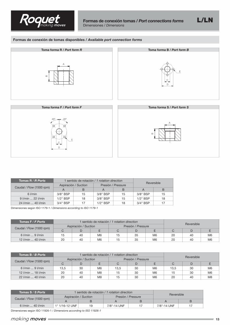
Formas de conexión tomas / Port connections formsDimensiones / Dimensions
Toma forma R / Port form R
Toma forma F / Port form F
Toma forma S / Port form S
A
B
45° 45°
�
�
E
B
A
Toma forma R / Port form R
Toma forma F / Port form F
Toma forma S / Port form S
A
B
45° 45°
�
�
E
B
A
1 sentido de rotación / 1 rotation directionAspiración / Suction Presión / Pressure
Caudal / Flow (1500 rpm)
6 l/min
9 l/min ... 22 l/min
24 l/min ... 40 l/min
A3/8" BSP1/2" BSP3/4" BSP
B151817
A3/8" BSP3/8" BSP1/2" BSP
B151518
A3/8" BSP1/2" BSP3/4" BSP
B151817
Reversible
Dimensiones según ISO 1179-1 / Dimensions according to ISO 1179-1
Tomas R / R Ports
Formas de conexión de tomas disponibles / Available port connection forms
Toma forma F / Port form F Toma forma S / Port form S
Toma forma R / Port form R Toma forma B / Port form B
A-A
A
A
B B
A
B
C
D
NormaStandard E 22141
MóduloModule 1,667
N° de dientesTeeth number 13
I
E
J
W
SAE base planaDiametral pitch 16/32Ángulo de presión 30°Número de dientes 13Ajuste lateralClase 1
SAE flat baseDiametral pitch 16/32Pressure angle 30°Teeth number 13Side fitType 1
G
H
01
10
23
19
09
R F B
Máx. par de arrastreMax. driving torque 250Nm
Máx. par de arrastreMax. driving torque 120Nm
Máx. par de arrastreMax. driving torque 300Nm
Máx. par de arrastreMax. driving torque xxxxxxxxxxxxxxxxxxNm
Máx. par de arrastreMax. driving torque 250Nm
Máx. par de arrastreMax. driving torque 300Nm
Máx. par de arrastreMax. driving torque 200Nm
Máx. par de arrastreMax. driving torque 320Nm
Máx. par de arrastreMax. driving torque 285Nm
Máx. par de arrastreMax. driving torque 120Nm
14,416Mx1
,5
25
24ConicidadTaper 3°
Chaveta Key Ø25x7
27Ø
11
E.C.A.F. 10f9
2426,5
17
40Chaveta
Key 36x6x6
M6
40 1,3
47
Diámetro ranura Groove diameter 24
6
25
21
43 1,3
Ø24,
6
M6x17
Diámetro ranura Groove diameter 23,6
14Mx1
,5
22
24,5
Chaveta Key Ø19x4
ConicidadTaper 1:8
16Mx1
,5
13,7
25
25
ChavetaKey Ø19x5
ConicidadTaper 1:5
27Ø
11
E.C.A.F. 10f7
21,7
921
,66
Ø
25
33,3
17
25 22
,22
22
,19
M6
ChavetaKey 25,4x6,35x6,35
7
60
f7
= =86106
3511
413
4
5
50
,75
f7
= =
98,5
120,5
42
128
150
9
11
8
105
f7
11
= =102122
48
145
165
7,2
3,22
52
f7
47,8
0,05
Ø
= =
82
18,3
82
106
144
13
2 tornillos fijación bomba M12x1,5 - 12k2 pump fixing screws M12x1,5 - 12k
9,5
10
1,6 f
7
= =
1460,1
14,3
A
B
C
D
45° 45°
CD
EE
21,5
20
21
2069
41
53
39
69
78
12,2
23,5
52,5
67
63,5 20
63
82
31
56
71
18
M6
49
40
17
26,5
24
ChavetaKey 36x6x6
L/LN
1 sentido de rotación / 1 rotation directionAspiración / Suction Presión / Pressure
Caudal / Flow (1500 rpm)
6 l/min ... 9 l/min
12 l/min ... 40 l/min
C1520
C2020
D4040
D4040
EM6M6
EM6M6
C1515
D3535
EM6M6
Tomas F / F PortsReversible
1 sentido de rotación / 1 rotation directionAspiración / Suction Presión / Pressure
Caudal / Flow (1500 rpm)
6 l/min ... 9 l/min
12 l/min ... 18 l/min
22 l/min ... 40 l/min
C13,52020
C13,51520
D304040
D303040
EM6M8M8
EM6M6M8
C13,51515
D303030
EM6M6M6
Tomas B / B PortsReversible
1 sentido de rotación / 1 rotation directionAspiración / Suction Presión / Pressure
Caudal / Flow (1500 rpm)
6 l/min ... 40 l/minA
1" 1/16-12 UNF
A
7/8"-14 UNF
A
7/8"-14 UNF
B
19
B
17
B
17
Dimensiones según ISO 11926-1 / Dimensions according to ISO 11926-1
Tomas S / S PortsReversible
E
45º 45º
C
D
E
C
D
A
B
A
B

14
Dimensiones / Dimensions L/LN
Eje forma E / Shaft form ESentido de giro derecha
Clockwise rotationSentido de giro izquierda
Counterclockwise rotation
Sentido de giro reversibleReversible rotation
IMATGE 1
IMATGE 2
Sentido de giro derechaClockwise rotation
Sentido de giro izquierdaCounterclockwise rotation
Sentido de giro reversibleReversible rotation
IMATGE 1
IMATGE 2
Sentido degiro derecha
Clockwiserotation
Sentido degiro izquierda
Counterclockwise rotation
Tapa tipo 10 / Front flange type 10
Eje forma R / Shaft form R
ReferenciaReference
1*6D▲10R
1*9D▲10R
1*12D▲10R
1*16D▲10R
1*18D▲10R
1*22D▲10R
1*24D▲10R
1*27D▲10R
1*35D▲10R
1*40D▲10R
LN - Peso kgLN - Weight kg
4
4,2
4,4
4,7
5
5,3
5,4
5,8
6,5
7,1
L - Peso kgL - Weight kg
3
3,2
3,3
3,5
3,7
3,9
4
4,3
4,8
5,3
B
89,6
93,1
96,4
100,8
103,3
107,6
109,8
113,4
122,4
126,4
A
42,5
42,5
44,6
49
49
49
49
49
56,5
64
Cilindrada cm³/revDisplacement cm³/rev
4
6
8
10,6
12
14,6
16
18
23,3
26,6
NOTA: Para dimensiones y tipos de tomas disponibles de bombas de giro derecha (D), izquierda (I) o reversible (R), consultar página 13.NOTE: For dimensions and available port types of clockwise (D), counterclockwise (I) or reversible (R) rotation pumps, see page 13.
* L Cuerpo de aluminio / Aluminium body. LN Cuerpo de fundición / Cast iron body. ▲ Forma de eje / Shaft form.
15,7
5
A
B
5
39,5
28
19Conicidad
Taper 1:8
ChavetaKey 16x3,2
96
32
71,5
= =
90
9,25
114,
5
9,5
17
E.CA.F 84
Tapa tipo 10 / Front Flange type 10
Eje forma E / Shaft form E
Eje forma E / Shaft form E
15
17
30
M6x1
16,6
36,5
16
M12x
1.25
36
,45
f7
15,7
5
A
B
5
39,5
28
19Conicidad
Taper 1:8
ChavetaKey 16x3,2
96
32
71,5
= =
90
9,25
114,
5
9,5
17
E.CA.F 84
Tapa tipo 10 / Front Flange type 10
Eje forma E / Shaft form E
Eje forma E / Shaft form E
15
17
30
M6x1
16,6
36,5
16
M12x
1.25
36
,45
f7
15,7
5
A
B
5
39,5
28
19Conicidad
Taper 1:8
ChavetaKey 16x3,2
96
32
71,5
= =
90
9,25
114,
5
9,5
17
E.CA.F 84
Tapa tipo 10 / Front Flange type 10
Eje forma E / Shaft form E
Eje forma E / Shaft form E
15
17
30
M6x1
16,6
36,5
16
M12x
1.25
36
,45
f7
15,7
5
A
B
5
39,5
28
19Conicidad
Taper 1:8
ChavetaKey 16x3,2
96
32
71,5
= =
90
9,25
114,
5
9,5
17
E.CA.F 84
Tapa tipo 10 / Front Flange type 10
Eje forma E / Shaft form E
Eje forma E / Shaft form E
15
17
30
M6x1
16,6
36,5
16
M12x
1.25
36
,45
f7 Ø36
,45
f7
114,
5
16,6
96
32
ChavetaKey Ø16x3,2
ConicidadTaper 1:8
39,5
36,5
90
71,5
5
28
16
19
17
30
A
B
9,5
15,7
5Ø17
Ø15
M6x
1
Ø9,25
= =
E.C.A.F. 84
M12
x1,2
5

15
Dimensiones / Dimensions L/LN
Eje forma E / Shaft form ESentido de giro derecha
Clockwise rotationSentido de giro izquierda
Counterclockwise rotation
Sentido de giro reversibleReversible rotation
IMATGE 1
IMATGE 2
Sentido de giro derechaClockwise rotation
Sentido de giro izquierdaCounterclockwise rotation
Sentido de giro reversibleReversible rotation
IMATGE 1
IMATGE 2
Sentido degiro derecha
Clockwiserotation
Sentido degiro izquierda
Counterclockwise rotation
Tapa tipo 31 / Front flange type 31
Eje forma C / Shaft form C
ReferenciaReference
1*6D▲31R
1*9D▲31R
1*12D▲31R
1*16D▲31R
1*18D▲31R
1*22D▲31R
1*24D▲31R
1*27D▲31R
1*35D▲31R
1*40D▲31R
LN - Peso kgLN - Weight kg
3,7
3,9
4,1
4,4
4,7
5
5,1
5,5
6,2
6,8
L - Peso kgL - Weight kg
2,7
2,9
3
3,2
3,4
3,6
3,7
4
4,5
5
B
86,6
90,1
93,4
97,8
100,3
104,6
106,8
110,4
119,4
123,4
A
39,5
39,5
41,6
46
46
46
46
46
53,5
61
Cilindrada cm³/revDisplacement cm³/rev
4
6
8
10,6
12
14,6
16
18
23,3
26,6
NOTA: Para dimensiones y tipos de tomas disponibles de bombas de giro derecha (D), izquierda (I) o reversible (R), consultar página 13.NOTE: For dimensions and available port types of clockwise (D), counterclockwise (I) or reversible (R) rotation pumps, see page 13.
* L Cuerpo de aluminio / Aluminium body. LN Cuerpo de fundición / Cast iron body. ▲ Forma de eje / Shaft form.
15,7
5
A
14,55
31
42,5 B
71,5
=
90
96
32
114,5
9,25
Tapa tipo 31 / Front Flange type 31
Eje forma E / Shaft form E
9,5
ChavetaKey Ø16x3.2
ConicidadTaper 1:8
E.CA.F 84
17
M12x
1.25
19
M6x1
17,6
16
25
32,5
Eje forma C / Shaft form C
36
,45
f7
15,7
5A
14,55
31
42,5 B
71,5
=
90
96
32
114,5
9,25
Tapa tipo 31 / Front Flange type 31
Eje forma E / Shaft form E
9,5
ChavetaKey Ø16x3.2
ConicidadTaper 1:8
E.CA.F 84
17
M12x
1.25
19
M6x1
17,6
16
25
32,5
Eje forma C / Shaft form C
36
,45
f7
15,7
5
A
14,55
31
42,5 B
71,5
=
90
96
32
114,5
9,25
Tapa tipo 31 / Front Flange type 31
Eje forma E / Shaft form E
9,5
ChavetaKey Ø16x3.2
ConicidadTaper 1:8
E.CA.F 84
17
M12x
1.25
19
M6x1
17,6
16
25
32,5
Eje forma C / Shaft form C
36
,45
f7
15,7
5
A
14,55
31
42,5 B
71,5
=
90
96
32
114,5
9,25
Tapa tipo 31 / Front Flange type 31
Eje forma E / Shaft form E
9,5
ChavetaKey Ø16x3.2
ConicidadTaper 1:8
E.CA.F 84
17
M12x
1.25
19
M6x1
17,6
16
25
32,5
Eje forma C / Shaft form C
36
,45
f7Ø
36,4
5 f7
ChavetaKey Ø16x3,2
ConicidadTaper 1:8
42,5
5
31
14,5
19
A
B
9,5
15,7
5Ø17
E.C.A.F. 84
M12
x1,2
5
114,
5
96
32
90
71,5
Ø9,25
= =
17,6
25
32,5
Ø16
M6x
1
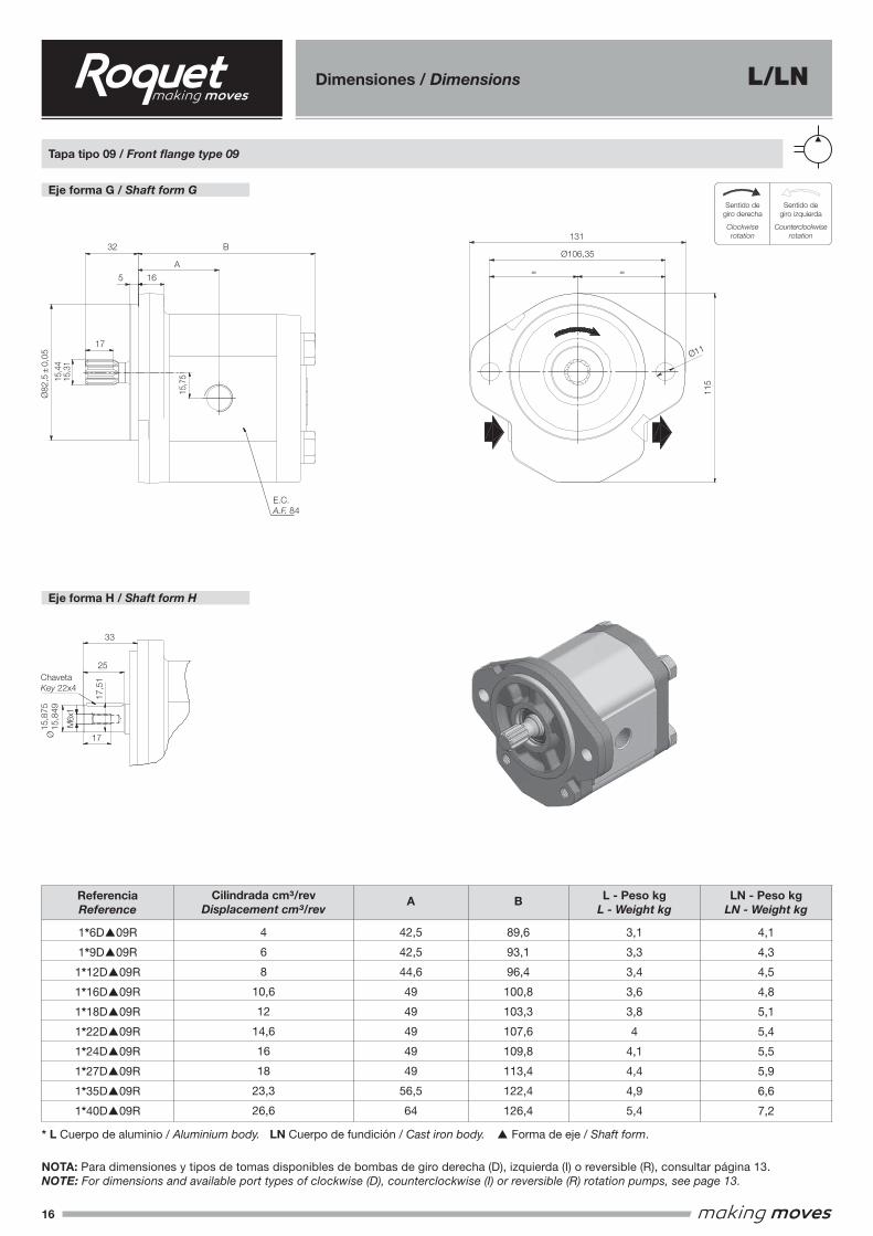
16
Dimensiones / Dimensions L/LN
Eje forma G / Shaft form GSentido de giro derecha
Clockwise rotationSentido de giro izquierda
Counterclockwise rotation
Sentido de giro reversibleReversible rotation
IMATGE 1
IMATGE 2
Sentido de giro derechaClockwise rotation
Sentido de giro izquierdaCounterclockwise rotation
Sentido de giro reversibleReversible rotation
IMATGE 1
IMATGE 2
Sentido degiro derecha
Clockwiserotation
Sentido degiro izquierda
Counterclockwise rotation
Tapa tipo 09 / Front flange type 09
Eje forma H / Shaft form H
ReferenciaReference
1*6D▲09R
1*9D▲09R
1*12D▲09R
1*16D▲09R
1*18D▲09R
1*22D▲09R
1*24D▲09R
1*27D▲09R
1*35D▲09R
1*40D▲09R
LN - Peso kgLN - Weight kg
4,1
4,3
4,5
4,8
5,1
5,4
5,5
5,9
6,6
7,2
L - Peso kgL - Weight kg
3,1
3,3
3,4
3,6
3,8
4
4,1
4,4
4,9
5,4
B
89,6
93,1
96,4
100,8
103,3
107,6
109,8
113,4
122,4
126,4
A
42,5
42,5
44,6
49
49
49
49
49
56,5
64
Cilindrada cm³/revDisplacement cm³/rev
4
6
8
10,6
12
14,6
16
18
23,3
26,6
NOTA: Para dimensiones y tipos de tomas disponibles de bombas de giro derecha (D), izquierda (I) o reversible (R), consultar página 13.NOTE: For dimensions and available port types of clockwise (D), counterclockwise (I) or reversible (R) rotation pumps, see page 13.
* L Cuerpo de aluminio / Aluminium body. LN Cuerpo de fundición / Cast iron body. ▲ Forma de eje / Shaft form.
15,7
5
165
32
17
A
B106,35
11
115
= =
15,4
415
,31
Eje forma G / Shaft form G
Tapa tipo 09 / Front Flange type 09
Eje forma H / Shaft form H
E.CA.F 84
M6x1
15,8
4915
,875
17,5
1
17
25
33
SAE Base planaDiametral pitch 16/32"Ángulo de presión 30°Número de dientes 9Ajuste lateralClase 1
SAE flat baseDiametral pitch 16/32"Pressure angle 30°Teeth number 9Side fitType 1
131
Chaveta Key 22x4
82,5
0,05
15,7
5165
32
17
A
B106,35
11
115
= =
15,4
415
,31
Eje forma G / Shaft form G
Tapa tipo 09 / Front Flange type 09
Eje forma H / Shaft form H
E.CA.F 84
M6x1
15,8
4915
,875
17,5
1
17
25
33
SAE Base planaDiametral pitch 16/32"Ángulo de presión 30°Número de dientes 9Ajuste lateralClase 1
SAE flat baseDiametral pitch 16/32"Pressure angle 30°Teeth number 9Side fitType 1
131
Chaveta Key 22x4
82,5
0,05
15,7
5
165
32
17
A
B106,35
11115
= =
15,4
415
,31
Eje forma G / Shaft form G
Tapa tipo 09 / Front Flange type 09
Eje forma H / Shaft form H
E.CA.F 84
M6x1
15,8
4915
,875
17,5
1
17
25
33
SAE Base planaDiametral pitch 16/32"Ángulo de presión 30°Número de dientes 9Ajuste lateralClase 1
SAE flat baseDiametral pitch 16/32"Pressure angle 30°Teeth number 9Side fitType 1
131
Chaveta Key 22x4
82,5
0,05
15,7
5
165
32
17
A
B106,35
11
115
= =
15,4
415
,31
Eje forma G / Shaft form G
Tapa tipo 09 / Front Flange type 09
Eje forma H / Shaft form H
E.CA.F 84
M6x1
15,8
4915
,875
17,5
1
17
25
33
SAE Base planaDiametral pitch 16/32"Ángulo de presión 30°Número de dientes 9Ajuste lateralClase 1
SAE flat baseDiametral pitch 16/32"Pressure angle 30°Teeth number 9Side fitType 1
131
Chaveta Key 22x4
82,5
0,05
115
17,5
1
32
25
33
131
Ø106,35
5 16
17
17
A
B
15,7
515,4
415
,31
M6x
1
Ø11
= =
E.C.A.F. 84
Ø82
,5 ±
0,0
5
ChavetaKey 22x4
Ø 1
5,87
5
15,8
49
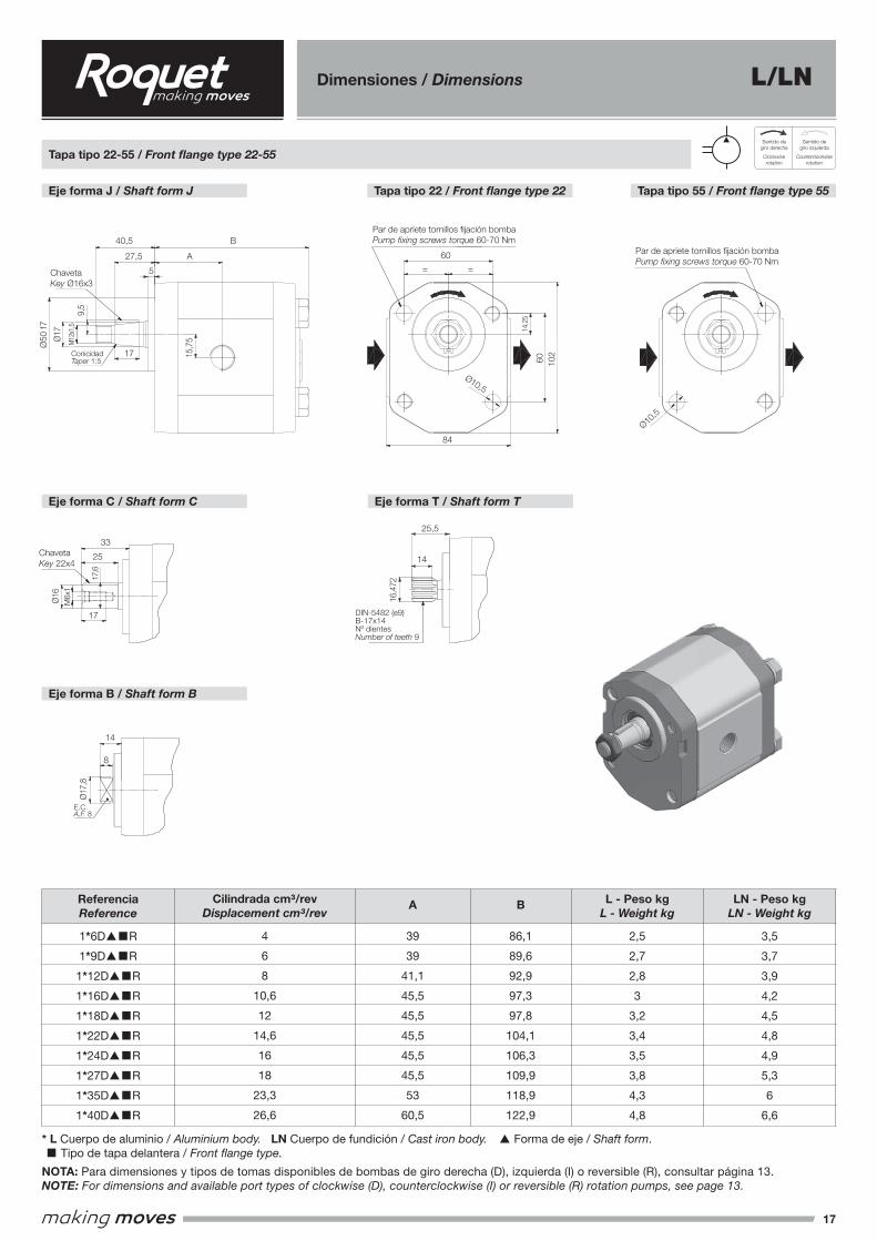
17
Dimensiones / Dimensions L/LN
Eje forma J / Shaft form J Tapa tipo 22 / Front flange type 22 Tapa tipo 55 / Front flange type 55
Sentido de giro derechaClockwise rotation
Sentido de giro izquierdaCounterclockwise rotation
Sentido de giro reversibleReversible rotation
IMATGE 1
IMATGE 2
Sentido de giro derechaClockwise rotation
Sentido de giro izquierdaCounterclockwise rotation
Sentido de giro reversibleReversible rotation
IMATGE 1
IMATGE 2
Sentido degiro derecha
Clockwiserotation
Sentido degiro izquierda
Counterclockwise rotation
Tapa tipo 22-55 / Front flange type 22-55
Eje forma C / Shaft form C
Eje forma B / Shaft form B
Eje forma T / Shaft form T
ReferenciaReference
1*6D▲■R
1*9D▲■R
1*12D▲■R
1*16D▲■R
1*18D▲■R
1*22D▲■R
1*24D▲■R
1*27D▲■R
1*35D▲■R
1*40D▲■R
LN - Peso kgLN - Weight kg
3,5
3,7
3,9
4,2
4,5
4,8
4,9
5,3
6
6,6
L - Peso kgL - Weight kg
2,5
2,7
2,8
3
3,2
3,4
3,5
3,8
4,3
4,8
B
86,1
89,6
92,9
97,3
97,8
104,1
106,3
109,9
118,9
122,9
A
39
39
41,1
45,5
45,5
45,5
45,5
45,5
53
60,5
Cilindrada cm³/revDisplacement cm³/rev
4
6
8
10,6
12
14,6
16
18
23,3
26,6
NOTA: Para dimensiones y tipos de tomas disponibles de bombas de giro derecha (D), izquierda (I) o reversible (R), consultar página 13.NOTE: For dimensions and available port types of clockwise (D), counterclockwise (I) or reversible (R) rotation pumps, see page 13.
* L Cuerpo de aluminio / Aluminium body. LN Cuerpo de fundición / Cast iron body. ▲ Forma de eje / Shaft form. ■ Tipo de tapa delantera / Front flange type.
15,7
5
17
40,5
5
A
B
17
9,5
M12x
1.5
27,5
60
60
= =
14,2
5
84
102Conicidad
Taper 1:5
Chaveta Key Ø16x3
Eje forma J / Shaft form J
Tapa tipo 22-55 / Front Flange type 22-55
Tipo 22 / Type 22
Eje forma C / Shaft form CEje forma T / Shaft form T
Eje forma B / Shaft form B
25,5
14
16,4
72
33
25
17,6
16
M6x1
17
14
8
17,8
E.C. A.F. 8
Chaveta Key 22x4
DIN-5482 (e9)B-17x14
Nº dientesNumber of teeth 9
Tipo 55 / Type 55
50
f7
Par de apriete tornillos fijación bombaPump fixing screws torque 60-70 Nm
Par de apriete tornillos fijación bombaPump fixing screws torque 60-70 Nm
10,5
10,5
15,7
5
17
40,5
5
A
B
17
9,5
M12x
1.5
27,5
60
60
= =
14,2
584
102Conicidad
Taper 1:5
Chaveta Key Ø16x3
Eje forma J / Shaft form J
Tapa tipo 22-55 / Front Flange type 22-55
Tipo 22 / Type 22
Eje forma C / Shaft form CEje forma T / Shaft form T
Eje forma B / Shaft form B
25,5
14
16,4
72
33
25
17,6
16
M6x1
17
14
8
17,8
E.C. A.F. 8
Chaveta Key 22x4
DIN-5482 (e9)B-17x14
Nº dientesNumber of teeth 9
Tipo 55 / Type 55
50
f7
Par de apriete tornillos fijación bombaPump fixing screws torque 60-70 Nm
Par de apriete tornillos fijación bombaPump fixing screws torque 60-70 Nm
10,5
10,5
15,7
5
17
40,5
5
A
B
17
9,5
M12x
1.5
27,5
60
60
= =
14,2
5
84
102Conicidad
Taper 1:5
Chaveta Key Ø16x3
Eje forma J / Shaft form J
Tapa tipo 22-55 / Front Flange type 22-55
Tipo 22 / Type 22
Eje forma C / Shaft form CEje forma T / Shaft form T
Eje forma B / Shaft form B
25,5
14
16,4
72
33
25
17,6
16
M6x1
17
14
8
17,8
E.C. A.F. 8
Chaveta Key 22x4
DIN-5482 (e9)B-17x14
Nº dientesNumber of teeth 9
Tipo 55 / Type 55
50
f7
Par de apriete tornillos fijación bombaPump fixing screws torque 60-70 Nm
Par de apriete tornillos fijación bombaPump fixing screws torque 60-70 Nm
10,5
10,5
15,7
5
17
40,5
5
A
B
17
9,5
M12x
1.5
27,5
60
60
= =
14,2
5
8410
2ConicidadTaper 1:5
Chaveta Key Ø16x3
Eje forma J / Shaft form J
Tapa tipo 22-55 / Front Flange type 22-55
Tipo 22 / Type 22
Eje forma C / Shaft form CEje forma T / Shaft form T
Eje forma B / Shaft form B
25,5
14
16,4
72
33
25
17,6
16
M6x1
17
14
8
17,8
E.C. A.F. 8
Chaveta Key 22x4
DIN-5482 (e9)B-17x14
Nº dientesNumber of teeth 9
Tipo 55 / Type 55
50
f7
Par de apriete tornillos fijación bombaPump fixing screws torque 60-70 Nm
Par de apriete tornillos fijación bombaPump fixing screws torque 60-70 Nm
10,5
10,5
E.C.A.F. 8
Ø50
f7
ChavetaKey Ø16x3
ChavetaKey 22x4
ConicidadTaper 1:5
Par de apriete tornillos fijación bombaPump fixing screws torque 60-70 Nm
DIN-5482 (e9)B-17x14Nº dientesNumber of teeth 9
Par de apriete tornillos fijación bombaPump fixing screws torque 60-70 Nm
40,5
5
27,5
17
A
B
9,5
15,7
5Ø17
M12
x1,5
102
60
60
84
Ø10,5
Ø10,5
= =
17,6
25
33
25,5
14
17
Ø16
Ø17
,8
16,4
72
M6x
1
14,2
5
14
8
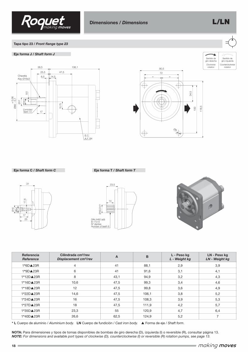
18
Dimensiones / Dimensions L/LN
Eje forma J / Shaft form JSentido de giro derecha
Clockwise rotationSentido de giro izquierda
Counterclockwise rotation
Sentido de giro reversibleReversible rotation
IMATGE 1
IMATGE 2
Sentido de giro derechaClockwise rotation
Sentido de giro izquierdaCounterclockwise rotation
Sentido de giro reversibleReversible rotation
IMATGE 1
IMATGE 2
Sentido degiro derecha
Clockwiserotation
Sentido degiro izquierda
Counterclockwise rotation
Tapa tipo 23 / Front flange type 23
Eje forma C / Shaft form C Eje forma T / Shaft form T
ReferenciaReference
1*6D▲23R
1*9D▲23R
1*12D▲23R
1*16D▲23R
1*18D▲23R
1*22D▲23R
1*24D▲23R
1*27D▲23R
1*35D▲23R
1*40D▲23R
LN - Peso kgLN - Weight kg
3,9
4,1
4,3
4,6
4,9
5,2
5,3
5,7
6,4
7
L - Peso kgL - Weight kg
2,9
3,1
3,2
3,4
3,6
3,8
3,9
4,2
4,7
5,2
B
88,1
91,6
94,9
99,3
99,8
106,1
108,3
111,9
120,9
124,9
A
41
41
43,1
47,5
47,5
47,5
47,5
47,5
55
62,5
Cilindrada cm³/revDisplacement cm³/rev
4
6
8
10,6
12
14,6
16
18
23,3
26,6
NOTA: Para dimensiones y tipos de tomas disponibles de bombas de giro derecha (D), izquierda (I) o reversible (R), consultar página 13.NOTE: For dimensions and available port types of clockwise (D), counterclockwise (I) or reversible (R) rotation pumps, see page 13.
* L Cuerpo de aluminio / Aluminium body. LN Cuerpo de fundición / Cast iron body. ▲ Forma de eje / Shaft form.
47,5
106,1
14,56,5
25,5
38,5
17
17
15,7
5
9,5
34,5
100
72= =
9
118,5
90,5
M12x
1.5
Eje forma J / Shaft form J
Tapa tipo 23 / Front Flange type 23
14
23,531
17,6
16
M6x1
17
25
16,5
h11
DIN-5482 (e9)B-17x14
Nº dientesNumber of teeth 9
Eje forma C / Shaft form C Eje forma T / Shaft form T
ConicidadTaper 1:5
Chaveta Key Ø16x3
E.C.A.F. 84
80
-0,
10,
06+
100
118,
5
34,5
17,6
31
90,5
72
17
25
M6x
1Ø
16
Ø9
= =
E.C.A.F. 84
ChavetaKey Ø16x3
ConicidadTaper 1:5
38,5
6,5 14,5
25,5
17
47,5
106,1
9,5
15,7
5Ø17
M12
x1,5
14
23,5
Ø16
,5 h
11
DIN-5482 (e9)B-17x14Nº dientesNumber of teeth 9
+
0,0
6Ø
80 -
0,1
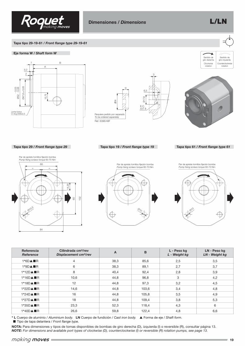
19
Eje forma W / Shaft form WSentido de giro derecha
Clockwise rotationSentido de giro izquierda
Counterclockwise rotation
Sentido de giro reversibleReversible rotation
IMATGE 1
IMATGE 2
Sentido de giro derechaClockwise rotation
Sentido de giro izquierdaCounterclockwise rotation
Sentido de giro reversibleReversible rotation
IMATGE 1
IMATGE 2
Sentido degiro derecha
Clockwiserotation
Sentido degiro izquierda
Counterclockwise rotation
Tapa tipo 29-19-61 / Front flange type 29-19-61
Tapa tipo 29 / Front flange type 29 Tapa tipo 19 / Front flange type 19 Tapa tipo 61 / Front flange type 61
Dimensiones / Dimensions L/LN
ReferenciaReference
1*6D▲■R
1*9D▲■R
1*12D▲■R
1*16D▲■R
1*18D▲■R
1*22D▲■R
1*24D▲■R
1*27D▲■R
1*35D▲■R
1*40D▲■R
LN - Peso kgLN - Weight kg
3,5
3,7
3,9
4,2
4,5
4,8
4,9
5,3
6
6,6
L - Peso kgL - Weight kg
2,5
2,7
2,8
3
3,2
3,4
3,5
3,8
4,3
4,8
B
85,6
89,1
92,4
96,8
97,3
103,6
105,8
109,4
118,4
122,4
A
38,3
38,3
40,4
44,8
44,8
44,8
44,8
44,8
52,3
59,8
Cilindrada cm³/revDisplacement cm³/rev
4
6
8
10,6
12
14,6
16
18
23,3
26,6
NOTA: Para dimensiones y tipos de tomas disponibles de bombas de giro derecha (D), izquierda (I) o reversible (R), consultar página 13.NOTE: For dimensions and available port types of clockwise (D), counterclockwise (I) or reversible (R) rotation pumps, see page 13.
* L Cuerpo de aluminio / Aluminium body. LN Cuerpo de fundición / Cast iron body. ▲ Forma de eje / Shaft form. ■ Tipo de tapa delantera / Front flange type.
A-A ( 1 )
A
A
B
3
7A
15,7
5
17,8
E.C A.F. 8
6,5
60
14,2
5
60= =
102
84
52-
0,06
0,03
-
Junta tórica O-ring Ø46x2.5
Tapa tipo 29-19-61/ Front Flange type 29-19-61Eje forma W / Shaft form W
Tapa tipo 29/ Front Flange type 29
Tapa tipo 19/ Front Flange type 19
Tapa tipo 61/ Front Flange type 61
12
30
47,8
0,05
2
3,2
10,5
10
10
Par de apriete tornillos fijación bombaPump fixing screws torque 60-70 Nm
Par de apriete tornillos fijación bombaPump fixing screws torque 60-70 Nm
Par de apriete tornillos fijación bombaPump fixing screws torque 60-70 Nm
Requiere pedido por separadoTo be ordered separately
Ref. 6396/48F
A-A ( 1 )
A
A
B
3
7A
15,7
5
17,8
E.C A.F. 8
6,5
60
14,2
5
60= =
102
8452
-0,
060,
03-
Junta tórica O-ring Ø46x2.5
Tapa tipo 29-19-61/ Front Flange type 29-19-61Eje forma W / Shaft form W
Tapa tipo 29/ Front Flange type 29
Tapa tipo 19/ Front Flange type 19
Tapa tipo 61/ Front Flange type 61
12
30
47,8
0,05
2
3,2
10,5
10
10
Par de apriete tornillos fijación bombaPump fixing screws torque 60-70 Nm
Par de apriete tornillos fijación bombaPump fixing screws torque 60-70 Nm
Par de apriete tornillos fijación bombaPump fixing screws torque 60-70 Nm
Requiere pedido por separadoTo be ordered separately
Ref. 6396/48F
E.C.A.F. 8
Junta tóricaO-ring Ø46x2,5
6,5
15,7
5
Ø17
,8
3
Ø47
,8 ±
0,0
5
-
0,03
Ø52
- 0
,06
Requiere pedido por separadoTo be ordered separately
Par de apriete tornillos fijación bombaPump fixing screws torque 60-70 Nm
Par de apriete tornillos fijación bombaPump fixing screws torque 60-70 Nm
Par de apriete tornillos fijación bombaPump fixing screws torque 60-70 Nm
Ref. 6396/48F
B7
3,2
2
A
60
84
Ø10,5 Ø10
= =
60 102
14,2
5
Ø10
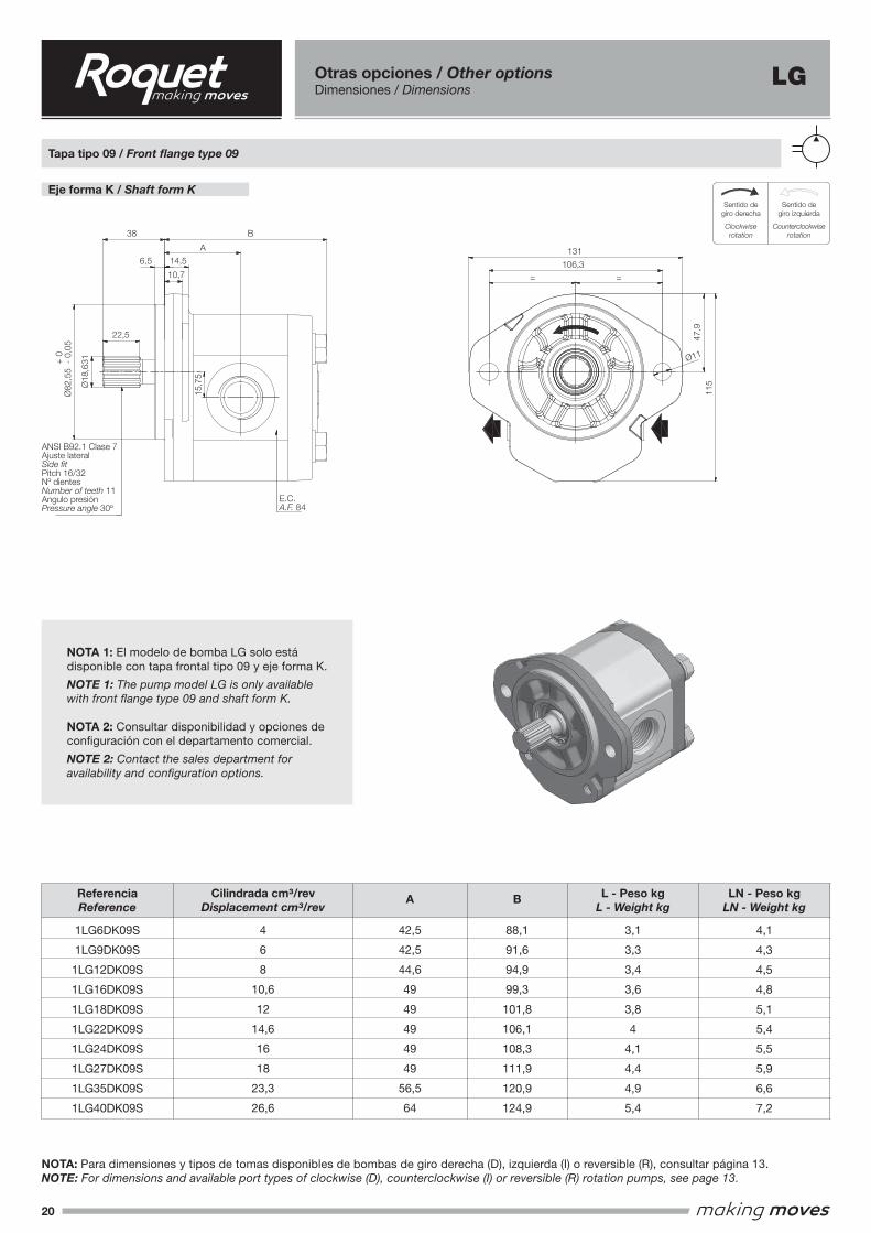
20
15,7
5
6,5
38
22,5
14,5
A
B
10,7
18,6
31
ANSI B92.1 Clase 7Ajuste lateral
Side fitPitch 16/32Nº dientes
Number of teeth 11Angulo presión
Pressure angle 30°
106,3
= =
11
131
115
47,9
Tapa tipo 09 / Front flange type 09
Eje forma K / Shaft form K
E.C.A.F. 84
82,5
5
-0,
050
+
15,7
5
6,5
38
22,5
14,5
A
B
10,7
18,6
31
ANSI B92.1 Clase 7Ajuste lateral
Side fitPitch 16/32Nº dientes
Number of teeth 11Angulo presión
Pressure angle 30°
106,3
= =
11
131
115
47,9
Tapa tipo 09 / Front flange type 09
Eje forma K / Shaft form K
E.C.A.F. 84
82,5
5
-0,
050
+
15,7
5
6,5
38
22,5
14,5
A
B
10,7
18,6
31
ANSI B92.1 Clase 7Ajuste lateral
Side fitPitch 16/32Nº dientes
Number of teeth 11Angulo presión
Pressure angle 30°
106,3
= =
11
131
115
47,9
Tapa tipo 09 / Front flange type 09
Eje forma K / Shaft form K
E.C.A.F. 84
82,5
5
-0,
050
+
LGOtras opciones / Other optionsDimensiones / Dimensions
NOTA 1: El modelo de bomba LG solo está disponible con tapa frontal tipo 09 y eje forma K.
NOTE 1: The pump model LG is only available with front flange type 09 and shaft form K.
NOTA 2: Consultar disponibilidad y opciones de configuración con el departamento comercial.
NOTE 2: Contact the sales department for availability and configuration options.
Eje forma K / Shaft form KSentido de giro derecha
Clockwise rotationSentido de giro izquierda
Counterclockwise rotation
Sentido de giro reversibleReversible rotation
IMATGE 1
IMATGE 2
Sentido de giro derechaClockwise rotation
Sentido de giro izquierdaCounterclockwise rotation
Sentido de giro reversibleReversible rotation
IMATGE 1
IMATGE 2
Sentido degiro derecha
Clockwiserotation
Sentido degiro izquierda
Counterclockwise rotation
Tapa tipo 09 / Front flange type 09
ReferenciaReference
1LG6DK09S
1LG9DK09S
1LG12DK09S
1LG16DK09S
1LG18DK09S
1LG22DK09S
1LG24DK09S
1LG27DK09S
1LG35DK09S
1LG40DK09S
B
88,1
91,6
94,9
99,3
101,8
106,1
108,3
111,9
120,9
124,9
Cilindrada cm³/revDisplacement cm³/rev
4
6
8
10,6
12
14,6
16
18
23,3
26,6
NOTA: Para dimensiones y tipos de tomas disponibles de bombas de giro derecha (D), izquierda (I) o reversible (R), consultar página 13.NOTE: For dimensions and available port types of clockwise (D), counterclockwise (I) or reversible (R) rotation pumps, see page 13.
LN - Peso kgLN - Weight kg
4,1
4,3
4,5
4,8
5,1
5,4
5,5
5,9
6,6
7,2
L - Peso kgL - Weight kg
3,1
3,3
3,4
3,6
3,8
4
4,1
4,4
4,9
5,4
A
42,5
42,5
44,6
49
49
49
49
49
56,5
64
47,9
115
38
131
106,314,5
10,7
22,5
6,5
B
A
Ø11
= =
ANSI B92.1 Clase 7Ajuste lateralSide fitPitch 16/32Nº dientesNumber of teeth 11Angulo presiónPressure angle 30º
E.C.A.F. 84
+
0Ø
82,5
5 -
0,05
Ø18
,631
15,7
5
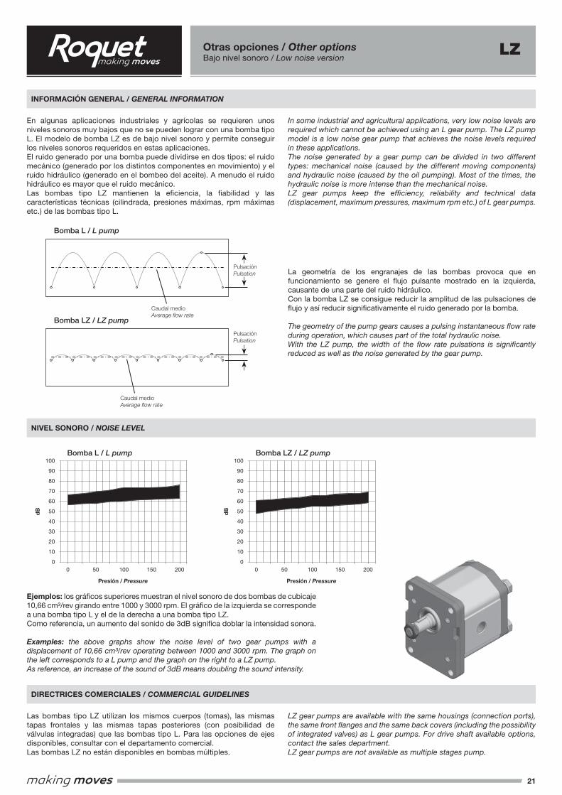
21
15,7
5
A
B
5
39,5
28
19Conicidad
Taper 1:8
ChavetaKey 16x3,2
96
32
71,5
= =
90
9,25
114,
5
9,5
17
E.CA.F 84
Tapa tipo 10 / Front Flange type 10
Eje forma E / Shaft form E
Eje forma E / Shaft form E
15
17
30
M6x1
16,6
36,5
16
M12x
1.25
36
,45
f7
INFORMACIÓN GENERAL / GENERAL INFORMATION
NIVEL SONORO / NOISE LEVEL
DIRECTRICES COMERCIALES / COMMERCIAL GUIDELINES
Otras opciones / Other optionsBajo nivel sonoro / Low noise version
LZ
En algunas aplicaciones industriales y agrícolas se requieren unos niveles sonoros muy bajos que no se pueden lograr con una bomba tipo L. El modelo de bomba LZ es de bajo nivel sonoro y permite conseguir los niveles sonoros requeridos en estas aplicaciones.El ruido generado por una bomba puede dividirse en dos tipos: el ruido mecánico (generado por los distintos componentes en movimiento) y el ruido hidráulico (generado en el bombeo del aceite). A menudo el ruido hidráulico es mayor que el ruido mecánico.Las bombas tipo LZ mantienen la eficiencia, la fiabilidad y las características técnicas (cilindrada, presiones máximas, rpm máximas etc.) de las bombas tipo L.
In some industrial and agricultural applications, very low noise levels are required which cannot be achieved using an L gear pump. The LZ pump model is a low noise gear pump that achieves the noise levels required in these applications.The noise generated by a gear pump can be divided in two different types: mechanical noise (caused by the different moving components) and hydraulic noise (caused by the oil pumping). Most of the times, the hydraulic noise is more intense than the mechanical noise.LZ gear pumps keep the efficiency, reliability and technical data (displacement, maximum pressures, maximum rpm etc.) of L gear pumps.
Las bombas tipo LZ utilizan los mismos cuerpos (tomas), las mismas tapas frontales y las mismas tapas posteriores (con posibilidad de válvulas integradas) que las bombas tipo L. Para las opciones de ejes disponibles, consultar con el departamento comercial.Las bombas LZ no están disponibles en bombas múltiples.
LZ gear pumps are available with the same housings (connection ports), the same front flanges and the same back covers (including the possibility of integrated valves) as L gear pumps. For drive shaft available options, contact the sales department.LZ gear pumps are not available as multiple stages pump.
La geometría de los engranajes de las bombas provoca que en funcionamiento se genere el flujo pulsante mostrado en la izquierda, causante de una parte del ruido hidráulico.Con la bomba LZ se consigue reducir la amplitud de las pulsaciones de flujo y así reducir significativamente el ruido generado por la bomba.
The geometry of the pump gears causes a pulsing instantaneous flow rate during operation, which causes part of the total hydraulic noise.With the LZ pump, the width of the flow rate pulsations is significantly reduced as well as the noise generated by the gear pump.
Ejemplos: los gráficos superiores muestran el nivel sonoro de dos bombas de cubicaje 10,66 cm³/rev girando entre 1000 y 3000 rpm. El gráfico de la izquierda se corresponde a una bomba tipo L y el de la derecha a una bomba tipo LZ.Como referencia, un aumento del sonido de 3dB significa doblar la intensidad sonora.
Examples: the above graphs show the noise level of two gear pumps with a displacement of 10,66 cm³/rev operating between 1000 and 3000 rpm. The graph on the left corresponds to a L pump and the graph on the right to a LZ pump.As reference, an increase of the sound of 3dB means doubling the sound intensity.
Caudal medioAverage flow rate
Caudal medioAverage flow rate
PulsaciónPulsation
PulsaciónPulsation
100
90
80
70
60
50
40
30
20
10
00 50 100 150 200
100
90
80
70
60
50
40
30
20
10
00 50 100 150 200
Bomba L / L pump
Bomba L / L pump Bomba LZ / LZ pump
Bomba LZ / LZ pump
dB
Presión / Pressure Presión / Pressure
dB
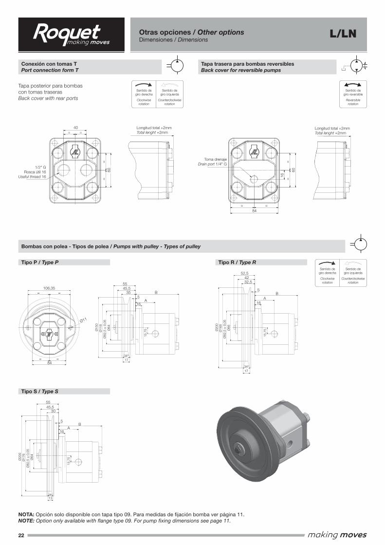
22
Otras opciones / Other optionsDimensiones / Dimensions
Conexión con tomas TPort connection form T
Tapa trasera para bombas reversiblesBack cover for reversible pumps
Tapa posterior para bombas con tomas traserasBack cover with rear ports
Sentido de giro derechaClockwise rotation
Sentido de giro izquierdaCounterclockwise rotation
Sentido de giro reversibleReversible rotation
IMATGE 1
IMATGE 2
Sentido de giro derechaClockwise rotation
Sentido de giro izquierdaCounterclockwise rotation
Sentido de giro reversibleReversible rotation
IMATGE 1
IMATGE 2
Sentido degiro derecha
Clockwiserotation
Sentido degiro izquierda
Counterclockwise rotation
Sentido de giro derechaClockwise rotation
Sentido de giro izquierdaCounterclockwise rotation
Sentido de giro reversibleReversible rotation
IMATGE 1
IMATGE 2
Sentido de giro derechaClockwise rotation
Sentido de giro izquierdaCounterclockwise rotation
Sentido de giro reversibleReversible rotation
IMATGE 1
IMATGE 2
Sentido degiro derecha
Clockwiserotation
Sentido degiro izquierda
Counterclockwise rotation
Sentido de giro derechaClockwise rotation
Sentido de giro izquierdaCounterclockwise rotation
Sentido de giro reversibleReversible rotation
IMATGE 1
IMATGE 2
Sentido degiro reversible
Reversible rotation
L/LN
NOTA: Opción solo disponible con tapa tipo 09. Para medidas de fijación bomba ver página 11.NOTE: Option only available with flange type 09. For pump fixing dimensions see page 11.
Tipo P / Type P Tipo R / Type R
Tipo S / Type S
Bombas con polea - Tipos de polea / Pumps with pulley - Types of pulley
==
40
1/2" GRosca útil 16
Useful thread 16
Longitud total +2mmTotal lenght +2mm
Longitud total +2mmTotal lenght +2mm
Toma drenajeDrain port 1/4" G
Tapa trasera para bombas reversiblesBack cover for reversible pumps
Tapa trasera para bombas con tomas traserasBack cover for pumps with rear ports
==
60
16
= =
84
= =
60
==
40
1/2" GRosca útil 16
Useful thread 16
Longitud total +2mmTotal lenght +2mm
Longitud total +2mmTotal lenght +2mm
Toma drenajeDrain port 1/4" G
Tapa trasera para bombas reversiblesBack cover for reversible pumps
Tapa trasera para bombas con tomas traserasBack cover for pumps with rear ports
==
60
16
= =
84
= =
60
106,35
84
11
16
15,7
5
A
B35
45,5
15
0
118 64
55
82,5
0,05
17
34°
20
0
16
8
52,5
42
32,5
17
34°
13
38°
64
55
45,5
30
16
A
B
82,5
0,05
82,5
0,05
16
A
B
66
5
5
5
20
0
17
6
Polea tipo R / R type pulley
Polea tipo P / P type pulleyTapa de polea / Pulley type
Polea tipo S / S type pulley
15,7
515
,75
106,35
84
11
16
15,7
5
A
B35
45,5
15
0
118 64
55
82,5
0,05
17
34°
20
0
16
8
52,5
42
32,5
17
34°
13
38°
64
55
45,5
30
16
A
B
82,5
0,05
82,5
0,05
16
A
B
66
5
5
5
20
0
17
6
Polea tipo R / R type pulley
Polea tipo P / P type pulleyTapa de polea / Pulley type
Polea tipo S / S type pulley
15,7
515
,75
106,35
84
11
16
15,7
5
A
B35
45,5
15
0
118 64
55
82,5
0,05
17
34°
20
0
16
8
52,5
42
32,5
17
34°
13
38°
64
55
45,5
30
16
A
B
82,5
0,05
82,5
0,05
16
A
B
66
5
5
5
20
0
17
6
Polea tipo R / R type pulley
Polea tipo P / P type pulleyTapa de polea / Pulley type
Polea tipo S / S type pulley
15,7
515
,75
106,35
84
11
16
15,7
5
A
B35
45,5
15
0
118 64
55
82,5
0,05
17
34°
20
0
16
8
52,5
42
32,5
17
34°
13
38°
64
55
45,5
30
16
A
B
82,5
0,05
82,5
0,05
16
A
B
66
5
5
5
20
0
17
6
Polea tipo R / R type pulley
Polea tipo P / P type pulleyTapa de polea / Pulley type
Polea tipo S / S type pulley
15,7
515
,75
106,35
84
11
16
15,7
5
A
B35
45,5
15
0
118 64
55
82,5
0,05
17
34°
20
0
16
8
52,5
42
32,5
17
34°
13
38°
64
55
45,5
30
16
A
B
82,5
0,05
82,5
0,05
16
A
B
66
5
5
5
20
0
17
6
Polea tipo R / R type pulley
Polea tipo P / P type pulleyTapa de polea / Pulley type
Polea tipo S / S type pulley
15,7
515
,75
Ø82
,5 ±
0,0
5
Ø82
,5 ±
0,0
5
Ø82
,5 ±
0,0
5
17
13
17
34º
38º
34º
Ø11
8
Ø17
6
Ø16
8
Ø64
Ø64
Ø66
15,7
5
15,7
5
15,7
5Ø15
0
Ø20
0
Ø20
0
55
55
42
16
16
16
35
30
B
B
B
A
A
A5
5
545,5
45,5
52,5
32,5
40
84
60 60
16
1/2" GRosca útil 16
Useful thread 16
Toma drenajeDrain port 1/4" G
Longitud total +2mmTotal lenght +2mm
Longitud total +2mmTotal lenght +2mm=
=
= =
=
=
= =
Ø11
106,35
84
=
=
=
=
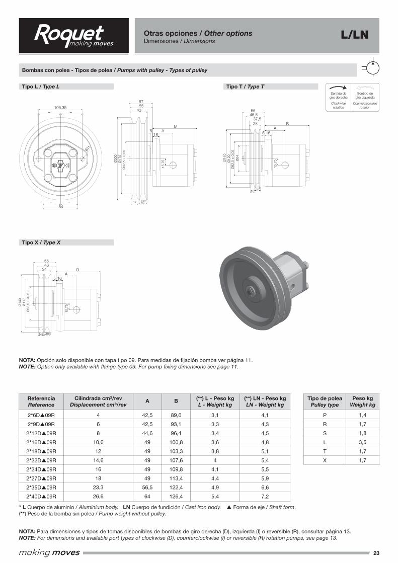
23
Sentido de giro derechaClockwise rotation
Sentido de giro izquierdaCounterclockwise rotation
Sentido de giro reversibleReversible rotation
IMATGE 1
IMATGE 2
Sentido de giro derechaClockwise rotation
Sentido de giro izquierdaCounterclockwise rotation
Sentido de giro reversibleReversible rotation
IMATGE 1
IMATGE 2
Sentido degiro derecha
Clockwiserotation
Sentido degiro izquierda
Counterclockwise rotation
NOTA: Opción solo disponible con tapa tipo 09. Para medidas de fijación bomba ver página 11.NOTE: Option only available with flange type 09. For pump fixing dimensions see page 11.
Tipo L / Type L
Tipo X / Type X
Tipo T / Type T
Bombas con polea - Tipos de polea / Pumps with pulley - Types of pulley
106,35
= =
11
84
==
A
55
43
37,5
28
55
57
45,5
64
14
0
12
0
15,7
5
16
A
B
5
82,5
0,05
1038°
17 34°
5
16
B
15,7
517
0
20
0
82,5
0,05
12,7 38°
34
55
46
82,5
0,05
15,7
5
16
A
B
14
0
11
7
Tapa de polea / Pulley type
Polea tipo L / L type pulley
Polea tipo T / T type pulley
Polea tipo X / X type pulley
5
106,35
= =
11
84
==
A
55
43
37,5
28
55
57
45,5
64
14
0
12
0
15,7
5
16
A
B
5
82,5
0,05
1038°
17 34°
5
16
B15
,75
170
20
0
82,5
0,05
12,7 38°
34
55
46
82,5
0,05
15,7
5
16
A
B
14
0
11
7
Tapa de polea / Pulley type
Polea tipo L / L type pulley
Polea tipo T / T type pulley
Polea tipo X / X type pulley
5
106,35
= =
11
84
==
A
55
43
37,5
28
55
57
45,5
64
14
0
12
0
15,7
5
16
A
B
5
82,5
0,05
1038°
17 34°
5
16
B
15,7
517
0
20
0
82,5
0,05
12,7 38°
34
55
46
82,5
0,05
15,7
5
16
A
B
14
0
11
7
Tapa de polea / Pulley type
Polea tipo L / L type pulley
Polea tipo T / T type pulley
Polea tipo X / X type pulley
5
106,35
= =
11
84
==
A
55
43
37,5
28
55
57
45,5
64
14
0
12
0
15,7
5
16
A
B
5
82,5
0,05
1038°
17 34°
5
16
B
15,7
517
0
20
0
82,5
0,05
12,7 38°
34
55
46
82,5
0,05
15,7
5
16
A
B
14
0
11
7
Tapa de polea / Pulley type
Polea tipo L / L type pulley
Polea tipo T / T type pulley
Polea tipo X / X type pulley
5
Otras opciones / Other optionsDimensiones / Dimensions
L/LN
NOTA: Para dimensiones y tipos de tomas disponibles de bombas de giro derecha (D), izquierda (I) o reversible (R), consultar página 13.NOTE: For dimensions and available port types of clockwise (D), counterclockwise (I) or reversible (R) rotation pumps, see page 13.
ReferenciaReference
2*6D▲09R
2*9D▲09R
2*12D▲09R
2*16D▲09R
2*18D▲09R
2*22D▲09R
2*24D▲09R
2*27D▲09R
2*35D▲09R
2*40D▲09R
Tipo de poleaPulley type
P
R
S
L
T
X
(**) LN - Peso kgLN - Weight kg
4,1
4,3
4,5
4,8
5,1
5,4
5,5
5,9
6,6
7,2
(**) L - Peso kgL - Weight kg
3,1
3,3
3,4
3,6
3,8
4
4,1
4,4
4,9
5,4
B
89,6
93,1
96,4
100,8
103,3
107,6
109,8
113,4
122,4
126,4
A
42,5
42,5
44,6
49
49
49
49
49
56,5
64
Cilindrada cm³/revDisplacement cm³/rev
4
6
8
10,6
12
14,6
16
18
23,3
26,6
Peso kgWeight kg
1,4
1,7
1,8
3,5
1,7
1,7
* L Cuerpo de aluminio / Aluminium body. LN Cuerpo de fundición / Cast iron body. ▲ Forma de eje / Shaft form.(**) Peso de la bomba sin polea / Pump weight without pulley.
Ø82
,5 ±
0,0
5
Ø82
,5 ±
0,0
5
17
12,7
34º
38º
Ø17
0
Ø11
7
15,7
5
15,7
5
Ø20
0
Ø14
0
57
55
16
16
43
34
B
B
A
A
5
5
5 16
55
46
Ø82
,5 ±
0,0
5
1038º
Ø12
0
Ø64
15,7
5Ø14
0
55
2837,5
BA
45,5
Ø11
106,35
84
=
=
=
=
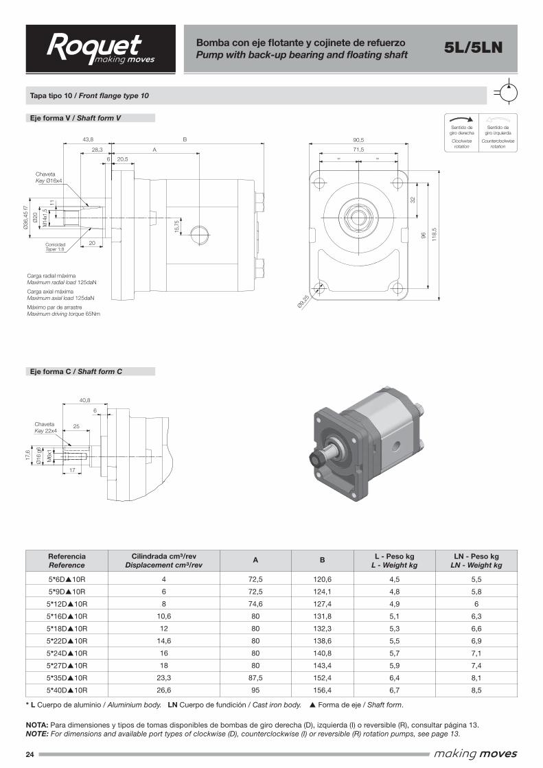
24
Eje forma V / Shaft form VSentido de giro derecha
Clockwise rotationSentido de giro izquierda
Counterclockwise rotation
Sentido de giro reversibleReversible rotation
IMATGE 1
IMATGE 2
Sentido de giro derechaClockwise rotation
Sentido de giro izquierdaCounterclockwise rotation
Sentido de giro reversibleReversible rotation
IMATGE 1
IMATGE 2
Sentido degiro derecha
Clockwiserotation
Sentido degiro izquierda
Counterclockwise rotation
Tapa tipo 10 / Front flange type 10
Eje forma C / Shaft form C
ReferenciaReference
5*6D▲10R
5*9D▲10R
5*12D▲10R
5*16D▲10R
5*18D▲10R
5*22D▲10R
5*24D▲10R
5*27D▲10R
5*35D▲10R
5*40D▲10R
LN - Peso kgLN - Weight kg
5,5
5,8
6
6,3
6,6
6,9
7,1
7,4
8,1
8,5
L - Peso kgL - Weight kg
4,5
4,8
4,9
5,1
5,3
5,5
5,7
5,9
6,4
6,7
B
120,6
124,1
127,4
131,8
132,3
138,6
140,8
143,4
152,4
156,4
A
72,5
72,5
74,6
80
80
80
80
80
87,5
95
Cilindrada cm³/revDisplacement cm³/rev
4
6
8
10,6
12
14,6
16
18
23,3
26,6
NOTA: Para dimensiones y tipos de tomas disponibles de bombas de giro derecha (D), izquierda (I) o reversible (R), consultar página 13.NOTE: For dimensions and available port types of clockwise (D), counterclockwise (I) or reversible (R) rotation pumps, see page 13.
* L Cuerpo de aluminio / Aluminium body. LN Cuerpo de fundición / Cast iron body. ▲ Forma de eje / Shaft form.
Bomba con eje flotante y cojinete de refuerzoPump with back-up bearing and floating shaft 5L/5LN
15,7
5
A
20,5
B
6
28,3
43,8
32
96 118,
5
90,5
71,5
= =
20
20
11
17,6
16
g6
25
40,8
6
Chaveta Key Ø16x4
ConicidadTaper 1:8
Eje forma C / Shaft form C
Eje forma V / Shaft form V
Tapa tipo 10 / Front flange type 10
Carga radial máximaMaximum radial load 125daN Carga axial máximaMaximum axial load 125 daN Máximo par de arrastreMaximum driving torque 65 Nm
36
,45
f7
M14x
1.5
9,25
17
M6x1
Chaveta Key 22x4
15,7
5A
20,5
B
6
28,3
43,8
32
96 118,
5
90,5
71,5
= =
20
20
11
17,6
16
g6
25
40,8
6
Chaveta Key Ø16x4
ConicidadTaper 1:8
Eje forma C / Shaft form C
Eje forma V / Shaft form V
Tapa tipo 10 / Front flange type 10
Carga radial máximaMaximum radial load 125daN Carga axial máximaMaximum axial load 125 daN Máximo par de arrastreMaximum driving torque 65 Nm
36
,45
f7
M14x
1.5
9,25
17
M6x1
Chaveta Key 22x4
15,7
5
A
20,5
B
6
28,3
43,8
32
96 118,
5
90,5
71,5
= =
20
20
11
17,6
16
g6
25
40,8
6
Chaveta Key Ø16x4
ConicidadTaper 1:8
Eje forma C / Shaft form C
Eje forma V / Shaft form V
Tapa tipo 10 / Front flange type 10
Carga radial máximaMaximum radial load 125daN Carga axial máximaMaximum axial load 125 daN Máximo par de arrastreMaximum driving torque 65 Nm
36
,45
f7
M14x
1.5
9,25
17
M6x1
Chaveta Key 22x4
118,
5
96
32
71,5
90,543,8
40,8
25
17
B
A28,3
20,5
20
6
15,7
5
Ø9,25
= =
Ø36
,45
f7
Ø16
g6
M6x
1
17,6
Ø20
11
ChavetaKey Ø16x4
ChavetaKey 22x4
Carga radial máximaMaximum radial load 125daN
Carga axial máximaMaximum axial load 125daN
Máximo par de arrastreMaximum driving torque 65Nm
ConicidadTaper 1:8
M14
x1,5
6
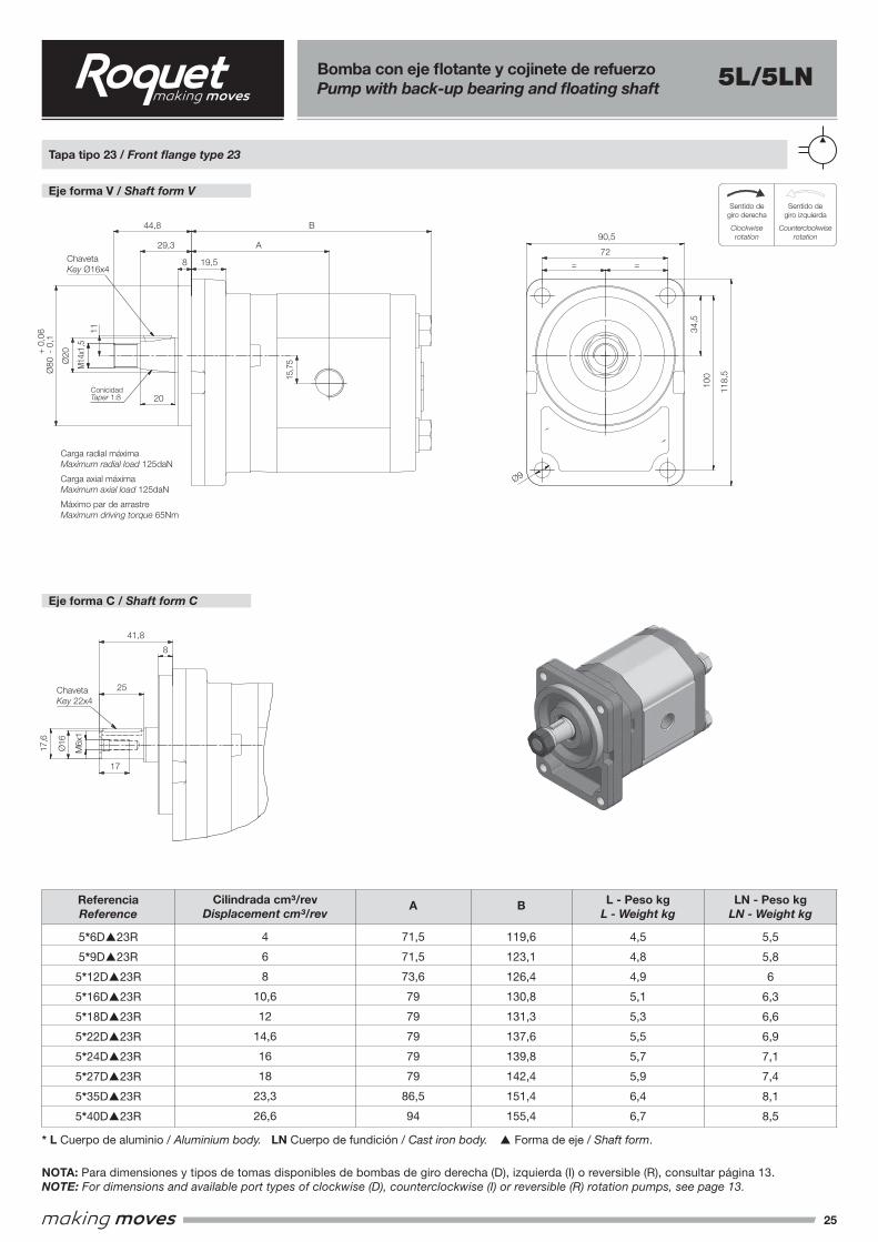
25
Eje forma V / Shaft form VSentido de giro derecha
Clockwise rotationSentido de giro izquierda
Counterclockwise rotation
Sentido de giro reversibleReversible rotation
IMATGE 1
IMATGE 2
Sentido de giro derechaClockwise rotation
Sentido de giro izquierdaCounterclockwise rotation
Sentido de giro reversibleReversible rotation
IMATGE 1
IMATGE 2
Sentido degiro derecha
Clockwiserotation
Sentido degiro izquierda
Counterclockwise rotation
Tapa tipo 23 / Front flange type 23
Eje forma C / Shaft form C
ReferenciaReference
5*6D▲23R
5*9D▲23R
5*12D▲23R
5*16D▲23R
5*18D▲23R
5*22D▲23R
5*24D▲23R
5*27D▲23R
5*35D▲23R
5*40D▲23R
LN - Peso kgLN - Weight kg
5,5
5,8
6
6,3
6,6
6,9
7,1
7,4
8,1
8,5
L - Peso kgL - Weight kg
4,5
4,8
4,9
5,1
5,3
5,5
5,7
5,9
6,4
6,7
B
119,6
123,1
126,4
130,8
131,3
137,6
139,8
142,4
151,4
155,4
A
71,5
71,5
73,6
79
79
79
79
79
86,5
94
Cilindrada cm³/revDisplacement cm³/rev
4
6
8
10,6
12
14,6
16
18
23,3
26,6
NOTA: Para dimensiones y tipos de tomas disponibles de bombas de giro derecha (D), izquierda (I) o reversible (R), consultar página 13.NOTE: For dimensions and available port types of clockwise (D), counterclockwise (I) or reversible (R) rotation pumps, see page 13.
* L Cuerpo de aluminio / Aluminium body. LN Cuerpo de fundición / Cast iron body. ▲ Forma de eje / Shaft form.
Bomba con eje flotante y cojinete de refuerzoPump with back-up bearing and floating shaft 5L/5LN
15,7
5
A
B
19,58
29,3
44,8
20
20
100
72
= =
118,5
34,5
90,5
9
11
17,6
16
25
41,8
8
Tapa tipo 23 / Front flange type 23
Eje forma V / Shaft form V
Eje forma C / Shaft form C
ConicidadTaper 1:8
Chaveta Key Ø16x4
80
-0,
10,
06+
M14x
1.5
Carga radial máximaMaximum radial load 125daN Carga axial máximaMaximum axial load 125 daN Máximo par de arrastreMaximum driving torque 65 Nm
17
M6x1
Chaveta Key 22x4
118,
5
100
34,5
72
90,544,8
41,8
25
17
B
A29,3
19,5
20
8
15,7
5
Ø9
= =
M6x
1
17,6
Ø16
Ø20
11
ChavetaKey Ø16x4
ChavetaKey 22x4
Carga radial máximaMaximum radial load 125daN
Carga axial máximaMaximum axial load 125daN
Máximo par de arrastreMaximum driving torque 65Nm
ConicidadTaper 1:8
M14
x1,5
8
+
0,0
6Ø
80 -
0,1
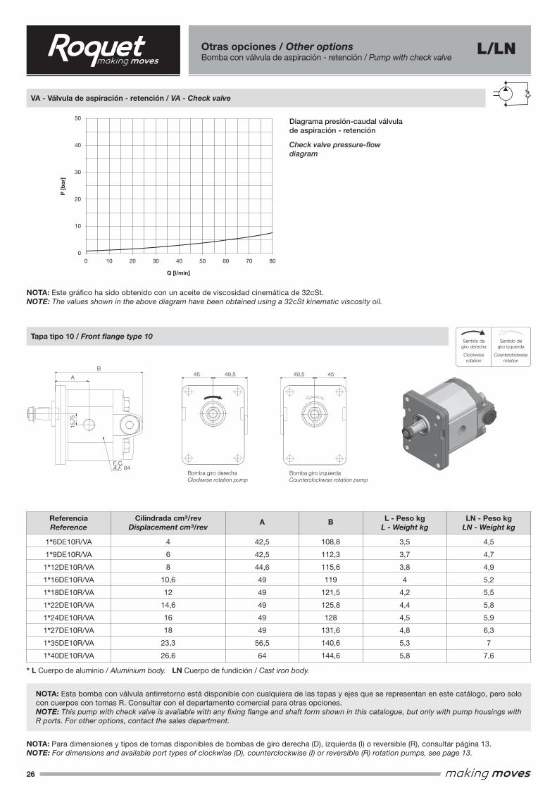
26
Sentido de giro derechaClockwise rotation
Sentido de giro izquierdaCounterclockwise rotation
Sentido de giro reversibleReversible rotation
IMATGE 1
IMATGE 2
Sentido de giro derechaClockwise rotation
Sentido de giro izquierdaCounterclockwise rotation
Sentido de giro reversibleReversible rotation
IMATGE 1
IMATGE 2
Sentido degiro derecha
Clockwiserotation
Sentido degiro izquierda
Counterclockwise rotation
VA - Válvula de aspiración - retención / VA - Check valve
Tapa tipo 10 / Front flange type 10
ReferenciaReference
1*6DE10R/VA
1*9DE10R/VA
1*12DE10R/VA
1*16DE10R/VA
1*18DE10R/VA
1*22DE10R/VA
1*24DE10R/VA
1*27DE10R/VA
1*35DE10R/VA
1*40DE10R/VA
LN - Peso kgLN - Weight kg
4,5
4,7
4,9
5,2
5,5
5,8
5,9
6,3
7
7,6
L - Peso kgL - Weight kg
3,5
3,7
3,8
4
4,2
4,4
4,5
4,8
5,3
5,8
B
108,8
112,3
115,6
119
121,5
125,8
128
131,6
140,6
144,6
Cilindrada cm³/revDisplacement cm³/rev
4
6
8
10,6
12
14,6
16
18
23,3
26,6
NOTA: Para dimensiones y tipos de tomas disponibles de bombas de giro derecha (D), izquierda (I) o reversible (R), consultar página 13.NOTE: For dimensions and available port types of clockwise (D), counterclockwise (I) or reversible (R) rotation pumps, see page 13.
NOTA: Este gráfico ha sido obtenido con un aceite de viscosidad cinemática de 32cSt.NOTE: The values shown in the above diagram have been obtained using a 32cSt kinematic viscosity oil.
NOTA: Esta bomba con válvula antirretorno está disponible con cualquiera de las tapas y ejes que se representan en este catálogo, pero solo con cuerpos con tomas R. Consultar con el departamento comercial para otras opciones.NOTE: This pump with check valve is available with any fixing flange and shaft form shown in this catalogue, but only with pump housings with R ports. For other options, contact the sales department.
* L Cuerpo de aluminio / Aluminium body. LN Cuerpo de fundición / Cast iron body.
Otras opciones / Other optionsBomba con válvula de aspiración - retención / Pump with check valve
L/LN15
,75
A
B
E.C.A.F. 84 Bomba giro derecha
Clockwise rotation pumpBomba giro izquierdaCounterclockwise rotation pump
Tapa tipo 10 / Front flange type 10
49,545 49,5 45
15,7
5
A
B
E.C.A.F. 84 Bomba giro derecha
Clockwise rotation pumpBomba giro izquierdaCounterclockwise rotation pump
Tapa tipo 10 / Front flange type 10
49,545 49,5 45
50
40
30
20
10
00 10 20 30 40 50 60 70 80
P [
bar
]
Q [l/min]
Diagrama presión-caudal válvula de aspiración - retención
Check valve pressure-flow diagram
A
42,5
42,5
44,6
49
49
49
49
49
56,5
64
49,5 49,545 45B
A
15,7
5
Bomba giro derechaClockwise rotation pump
Bomba giro izquierdaCounterclockwise rotation pump
E.C.A.F. 84
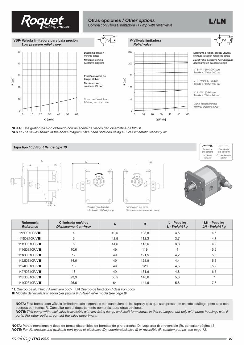
27
Sentido de giro derechaClockwise rotation
Sentido de giro izquierdaCounterclockwise rotation
Sentido de giro reversibleReversible rotation
IMATGE 1
IMATGE 2
Sentido de giro derechaClockwise rotation
Sentido de giro izquierdaCounterclockwise rotation
Sentido de giro reversibleReversible rotation
IMATGE 1
IMATGE 2
Sentido degiro derecha
Clockwiserotation
Sentido degiro izquierda
Counterclockwise rotation
Tapa tipo 10 / Front flange type 10
ReferenciaReference
1*6DE10R/V■
1*9DE10R/V■
1*12DE10R/V■
1*16DE10R/V■
1*18DE10R/V■
1*22DE10R/V■
1*24DE10R/V■
1*27DE10R/V■
1*35DE10R/V■
1*40DE10R/V■
LN - Peso kgLN - Weight kg
4,5
4,7
4,9
5,2
5,5
5,8
5,9
6,3
7
7,6
L - Peso kgL - Weight kg
3,5
3,7
3,8
4
4,2
4,4
4,5
4,8
5,3
5,8
B
108,8
112,3
115,6
119
121,5
125,8
128
131,6
140,6
144,6
Cilindrada cm³/revDisplacement cm³/rev
4
6
8
10,6
12
14,6
16
18
23,3
26,6
NOTA: Para dimensiones y tipos de tomas disponibles de bombas de giro derecha (D), izquierda (I) o reversible (R), consultar página 13.NOTE: For dimensions and available port types of clockwise (D), counterclockwise (I) or reversible (R) rotation pumps, see page 13.
NOTA: Este gráfico ha sido obtenido con un aceite de viscosidad cinemática de 32cSt.NOTE: The values shown in the above diagram have been obtained using a 32cSt kinematic viscosity oil.
NOTA: Esta bomba con válvula limitadora está disponible con cualquiera de las tapas y ejes que se representan en este catálogo, pero solo con cuerpos con tomas R. Consultar con el departamento comercial para otras opciones.NOTE: This pump with relief valve is available with any fixing flange and shaft form shown in this catalogue, but only with pump housings with R ports. For other options, contact the sales department.
* L Cuerpo de aluminio / Aluminium body. LN Cuerpo de fundición / Cast iron body.■ Modelo de válvula limitadora (ver página 9) / Relief valve model (see page 9).
Otras opciones / Other optionsBomba con válvula limitadora / Pump with relief valve
L/LN
V13 - V43 (180-250 bar)Tarada a / Set at 200 bar
V12 - V42 (85-175 bar)Tarada a / Set at 160 bar
V11 - V41 (5-80 bar)Tarada a / Set at 80 bar
Curva presión mínimaMinimal pressure curve
Curva presión mínimaMinimal pressure curve
50
40
30
20
10
0
250
200
150
100
50
00 010 1020 2030 3040 4050 5060 60
P [
bar
]
P [
bar
]
Q [l/min] Q [l/min]
Diagrama presión mínima taraje
Minimum setting pressure diagram
Presión máxima de taraje: 20 bar
Maximum set pressure: 20 bar
Diagrama presión-caudal válvula limitadora según rango de taraje
Relief valve pressure-flow diagram depending on pressure range
A
42,5
42,5
44,6
49
49
49
49
49
56,5
64
VBP- Válvula limitadora para baja presión Low pressure relief valve
V- Válvula limitadora Relief valve
15,7
5
87 87
A
B
E.C.A.F. 84
43
15,7
5
15,7
5
Bomba giro derechaClockwise rotation pump
Bomba giro izquierdaCounterclockwise rotation pump
Tapa tipo 10 / Front flange type 10
15,7
587 87
A
B
E.C.A.F. 84
43
15,7
5
15,7
5
Bomba giro derechaClockwise rotation pump
Bomba giro izquierdaCounterclockwise rotation pump
Tapa tipo 10 / Front flange type 10
87 87B
A 43
15,7
5
15,7
5
15,7
5
Bomba giro derechaClockwise rotation pump
Bomba giro izquierdaCounterclockwise rotation pump
E.C.A.F. 84
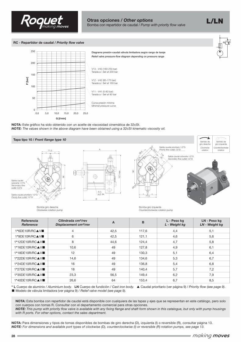
28
Sentido de giro derechaClockwise rotation
Sentido de giro izquierdaCounterclockwise rotation
Sentido de giro reversibleReversible rotation
IMATGE 1
IMATGE 2
Sentido de giro derechaClockwise rotation
Sentido de giro izquierdaCounterclockwise rotation
Sentido de giro reversibleReversible rotation
IMATGE 1
IMATGE 2
Sentido degiro derecha
Clockwiserotation
Sentido degiro izquierda
Counterclockwise rotation
RC - Repartidor de caudal / Priority flow valve
Tapa tipo 10 / Front flange type 10
NOTA: Para dimensiones y tipos de tomas disponibles de bombas de giro derecha (D), izquierda (I) o reversible (R), consultar página 13.NOTE: For dimensions and available port types of clockwise (D), counterclockwise (I) or reversible (R) rotation pumps, see page 13.
NOTA: Este gráfico ha sido obtenido con un aceite de viscosidad cinemática de 32cSt.NOTE: The values shown in the above diagram have been obtained using a 32cSt kinematic viscosity oil.
NOTA: Esta bomba con repartidor de caudal está disponible con cualquiera de las tapas y ejes que se representan en este catálogo, pero solo con cuerpos con tomas R. Consultar con el departamento comercial para otras opciones.NOTE: This pump with priority flow valve is available with any fixing flange and shaft form shown in this catalogue, but only with pump housings with R ports. For other options, contact the sales department.
* L Cuerpo de aluminio / Aluminium body. LN Cuerpo de fundición / Cast iron body. ▲ Caudal prioritario (ver página 9) / Priority flow (see page 9).■ Modelo de válvula limitadora (ver página 9) / Relief valve model (see page 9).
Otras opciones / Other optionsBomba con repartidor de caudal / Pump with priority flow valve
L/LN
V13 - V43 (180-250 bar)Tarada a / Set at 200 bar
V12 - V42 (85-175 bar)Tarada a / Set at 160 bar
V11 - V41 (5-80 bar)Tarada a / Set at 80 bar
Curva presión mínimaMinimal pressure curve
250
200
150
100
50
025,00,0 5,0 10,0 15,0 20,0
P [
bar
]
Q [l/min]
Diagrama presión-caudal válvula limitadora según rango de taraje
Relief valve pressure-flow diagram depending on pressure range
ReferenciaReference
1*6DE10R/RC▲V■
1*9DE10R/RC▲V■
1*12DE10R/RC▲V■
1*16DE10R/RC▲V■
1*18DE10R/RC▲V■
1*22DE10R/RC▲V■
1*24DE10R/RC▲V■
1*27DE10R/RC▲V■
1*35DE10R/RC▲V■
1*40DE10R/RC▲V■
LN - Peso kgLN - Weight kg
5,1
5,6
5,8
6,1
6,4
6,7
6,8
7,2
7,9
8,5
L - Peso kgL - Weight kg
4,4
4,6
4,7
4,9
5,1
5,3
5,4
5,7
6,2
6,7
B
117,6
121,1
124,4
127,8
130,3
134,6
136,8
140,4
149,4
153,4
Cilindrada cm³/revDisplacement cm³/rev
4
6
8
10,6
12
14,6
16
18
23,3
26,6
A
42,5
42,5
44,6
49
49
49
49
49
56,5
64
E.C.A.F. 84
A
157
max.
B
38,5
= =
40
32,5
118
96
9
9,25
71,5
Tapa tipo 10 / Front flange type 10Eje forma E / Shaft form E
Salida caudal sobrante 1/2"GSecondary flow outlet 1/2"G
Salida caudal prioritario 1/2"GPriority flow outlet 1/2"G
E.C.A.F. 84
A
157
max.
B
38,5
= =
40
32,5
118
96
99,25
71,5
Tapa tipo 10 / Front flange type 10Eje forma E / Shaft form E
Salida caudal sobrante 1/2"GSecondary flow outlet 1/2"G
Salida caudal prioritario 1/2"GPriority flow outlet 1/2"G
E.C.A.F. 84
A
157
max.
B
38,5
= =
40
32,5
118
96
9
9,25
71,5
Tapa tipo 10 / Front flange type 10Eje forma E / Shaft form E
Salida caudal sobrante 1/2"GSecondary flow outlet 1/2"G
Salida caudal prioritario 1/2"GPriority flow outlet 1/2"G
E.C.A.F. 84
A
157
max.
B
38,5
= =
118
71,5
Salida caudal sobrante 1/2"GSecondary flow outlet 1/2"G
Salida caudal prioritario 1/2"GPriority flow outlet 1/2"G
96
9,25
40
32,5
9
71,5
71,5
A
B
=
=
=
=
40
32,5
Ø9,25
38,5
38,5
118
9
96
96
157
max
.
Salida caudal sobrante 1/2"GSecondary flow outlet 1/2"G
Salida caudal prioritario 1/2"GPriority flow outlet 1/2"G
Salida caudal sobrante 1/2"GSecondary flow outlet 1/2"G
Salida caudal prioritario 1/2"GPriority flow outlet 1/2"G
E.C.A.F. 84
Bomba giro derechaClockwise rotation pump
Bomba giro izquierdaCounterclockwise rotation pump
Ø9,25
40
32,5118
9
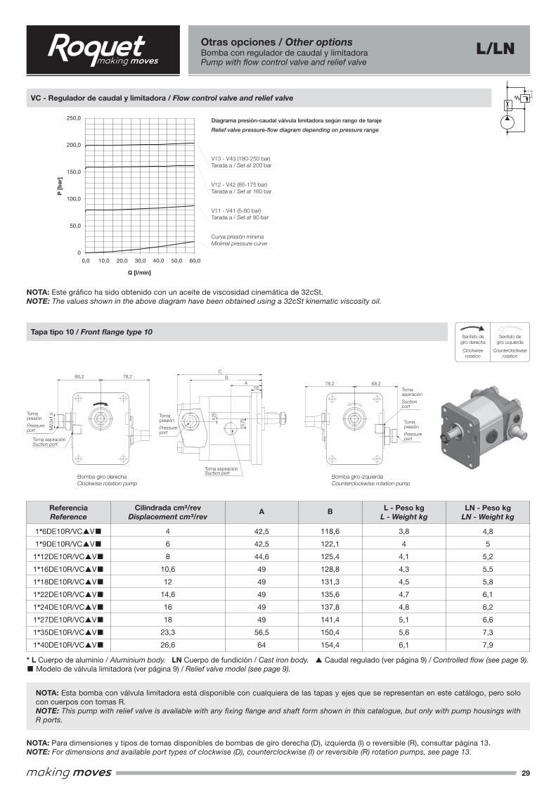
29
Sentido de giro derechaClockwise rotation
Sentido de giro izquierdaCounterclockwise rotation
Sentido de giro reversibleReversible rotation
IMATGE 1
IMATGE 2
Sentido de giro derechaClockwise rotation
Sentido de giro izquierdaCounterclockwise rotation
Sentido de giro reversibleReversible rotation
IMATGE 1
IMATGE 2
Sentido degiro derecha
Clockwiserotation
Sentido degiro izquierda
Counterclockwise rotation
VC - Regulador de caudal y limitadora / Flow control valve and relief valve
Tapa tipo 10 / Front flange type 10
NOTA: Para dimensiones y tipos de tomas disponibles de bombas de giro derecha (D), izquierda (I) o reversible (R), consultar página 13.NOTE: For dimensions and available port types of clockwise (D), counterclockwise (I) or reversible (R) rotation pumps, see page 13.
NOTA: Este gráfico ha sido obtenido con un aceite de viscosidad cinemática de 32cSt.NOTE: The values shown in the above diagram have been obtained using a 32cSt kinematic viscosity oil.
NOTA: Esta bomba con válvula limitadora está disponible con cualquiera de las tapas y ejes que se representan en este catálogo, pero solo con cuerpos con tomas R.NOTE: This pump with relief valve is available with any fixing flange and shaft form shown in this catalogue, but only with pump housings with R ports.
* L Cuerpo de aluminio / Aluminium body. LN Cuerpo de fundición / Cast iron body. ▲ Caudal regulado (ver página 9) / Controlled flow (see page 9).■ Modelo de válvula limitadora (ver página 9) / Relief valve model (see page 9).
Otras opciones / Other optionsBomba con regulador de caudal y limitadoraPump with flow control valve and relief valve
L/LN
V13 - V43 (180-250 bar)Tarada a / Set at 200 bar
V12 - V42 (85-175 bar)Tarada a / Set at 160 bar
V11 - V41 (5-80 bar)Tarada a / Set at 80 bar
Curva presión mínimaMinimal pressure curve
250,0
200,0
150,0
100,0
50,0
050,0 60,00,0 10,0 20,0 30,0 40,0
P [
bar
]
Q [l/min]
Diagrama presión-caudal válvula limitadora según rango de taraje
Relief valve pressure-flow diagram depending on pressure range
ReferenciaReference
1*6DE10R/VC▲V■
1*9DE10R/VC▲V■
1*12DE10R/VC▲V■
1*16DE10R/VC▲V■
1*18DE10R/VC▲V■
1*22DE10R/VC▲V■
1*24DE10R/VC▲V■
1*27DE10R/VC▲V■
1*35DE10R/VC▲V■
1*40DE10R/VC▲V■
LN - Peso kgLN - Weight kg
4,8
5
5,2
5,5
5,8
6,1
6,2
6,6
7,3
7,9
L - Peso kgL - Weight kg
3,8
4
4,1
4,3
4,5
4,7
4,8
5,1
5,6
6,1
B
118,6
122,1
125,4
128,8
131,3
135,6
137,8
141,4
150,4
154,4
Cilindrada cm³/revDisplacement cm³/rev
4
6
8
10,6
12
14,6
16
18
23,3
26,6
A
42,5
42,5
44,6
49
49
49
49
49
56,5
64
15,7
5
4,25
A
B
C
16
78,268,2
Toma aspiraciónSuction port
Toma presiónPressure port
BOMBA GIRO DERECHACLOCKWISE ROTATION
BOMBA GIRO IZQUIERDACOUNTERCLOCKWISE ROTATION
78,2 68,2
Toma aspiraciónSuction port
Toma presiónPressure port
Toma presiónPressure port
Toma aspiraciónSuction port
M22x
1.5
15,7
5
4,25
A
B
C
16
78,268,2
Toma aspiraciónSuction port
Toma presiónPressure port
BOMBA GIRO DERECHACLOCKWISE ROTATION
BOMBA GIRO IZQUIERDACOUNTERCLOCKWISE ROTATION
78,2 68,2
Toma aspiraciónSuction port
Toma presiónPressure port
Toma presiónPressure port
Toma aspiraciónSuction port
M22x
1.5
15,7
5
4,25
A
B
C
16
78,268,2
Toma aspiraciónSuction port
Toma presiónPressure port
BOMBA GIRO DERECHACLOCKWISE ROTATION
BOMBA GIRO IZQUIERDACOUNTERCLOCKWISE ROTATION
78,2 68,2
Toma aspiraciónSuction port
Toma presiónPressure port
Toma presiónPressure port
Toma aspiraciónSuction port
M22x
1.5
15,7
5
A
B
E.C.A.F. 84 Bomba giro derecha
Clockwise rotation pumpBomba giro izquierdaCounterclockwise rotation pump
Tapa tipo 10 / Front flange type 10
49,545 49,5 45
15,7
5
A
B
E.C.A.F. 84 Bomba giro derecha
Clockwise rotation pumpBomba giro izquierdaCounterclockwise rotation pump
Tapa tipo 10 / Front flange type 10
49,545 49,5 45
Toma presión
Pressure port
Toma presión
Pressure port
Toma presión
Pressure portToma aspiración
Suction port
Toma aspiraciónSuction port
Toma aspiración
Suction port
68,2
68,2
78,2
78,2
CB
A16
M22
x1,5
Bomba giro derechaClockwise rotation pump
Bomba giro izquierdaCounterclockwise rotation pump
15,7
54,25
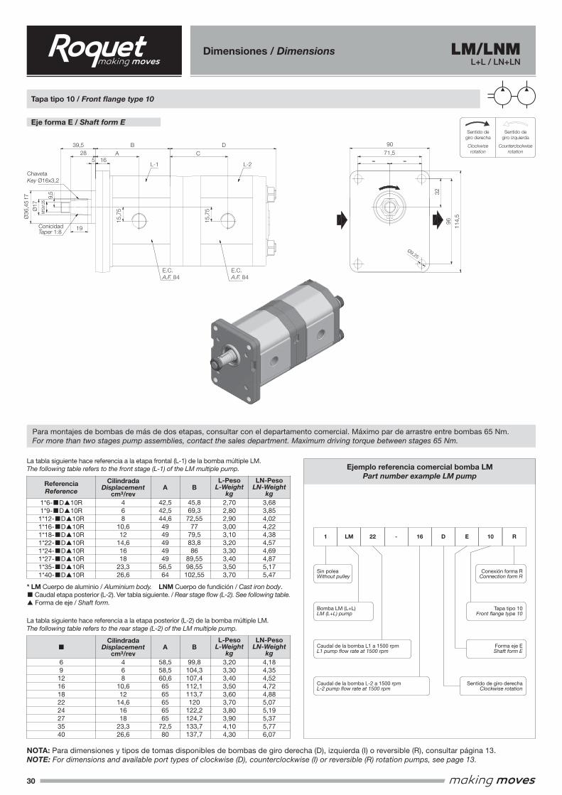
30
Eje forma E / Shaft form ESentido de giro derecha
Clockwise rotationSentido de giro izquierda
Counterclockwise rotation
Sentido de giro reversibleReversible rotation
IMATGE 1
IMATGE 2
Sentido de giro derechaClockwise rotation
Sentido de giro izquierdaCounterclockwise rotation
Sentido de giro reversibleReversible rotation
IMATGE 1
IMATGE 2
Sentido degiro derecha
Clockwiserotation
Sentido degiro izquierda
Counterclockwise rotation
LM/LNML+L / LN+LN
Tapa tipo 10 / Front flange type 10
Para montajes de bombas de más de dos etapas, consultar con el departamento comercial. Máximo par de arrastre entre bombas 65 Nm.For more than two stages pump assemblies, contact the sales department. Maximum driving torque between stages 65 Nm.
La tabla siguiente hace referencia a la etapa posterior (L-2) de la bomba múltiple LM.The following table refers to the rear stage (L-2) of the LM multiple pump.
La tabla siguiente hace referencia a la etapa frontal (L-1) de la bomba múltiple LM.The following table refers to the front stage (L-1) of the LM multiple pump.
* LM Cuerpo de aluminio / Aluminium body. LNM Cuerpo de fundición / Cast iron body.■ Caudal etapa posterior (L-2). Ver tabla siguiente. / Rear stage flow (L-2). See following table.▲ Forma de eje / Shaft form.
Ejemplo referencia comercial bomba LMPart number example LM pump
Sin poleaWithout pulley
Bomba LM (L+L)LM (L+L) pump
Caudal de la bomba L1 a 1500 rpmL1 pump flow rate at 1500 rpm
Caudal de la bomba L-2 a 1500 rpmL-2 pump flow rate at 1500 rpm
Sentido de giro derechaClockwise rotation
Conexión forma RConnection form R
1 LM 22 - 16 D E 10 R
Tapa tipo 10Front flange type 10
Forma eje EShaft form E
691216182224273540
Dimensiones / Dimensions
NOTA: Para dimensiones y tipos de tomas disponibles de bombas de giro derecha (D), izquierda (I) o reversible (R), consultar página 13.NOTE: For dimensions and available port types of clockwise (D), counterclockwise (I) or reversible (R) rotation pumps, see page 13.
15,7
5
15,7
5
B
A
16
D
C
32
96 114,
5
90
71,5
= =
9,25
Eje forma E / Shaft form E
Tapa tipo 10 / Front Flange type 10
5
28
39,5
19
17
9,5
M12x
1.25
ChavetaKey Ø16x3.2
ConicidadTaper 1:8
E.C.A.F. 84
E.C.A.F. 84
L-1 L-2
36
,45
f7
15,7
5
15,7
5
B
A
16
D
C
32
96 114,
5
90
71,5
= =
9,25
Eje forma E / Shaft form E
Tapa tipo 10 / Front Flange type 10
5
28
39,5
19
17
9,5
M12x
1.25
ChavetaKey Ø16x3.2
ConicidadTaper 1:8
E.C.A.F. 84
E.C.A.F. 84
L-1 L-2
36
,45
f7
15,7
5
15,7
5
B
A
16
D
C
32
96 114,
5
90
71,5
= =
9,25
Eje forma E / Shaft form E
Tapa tipo 10 / Front Flange type 10
5
28
39,5
19
17
9,5
M12x
1.25
ChavetaKey Ø16x3.2
ConicidadTaper 1:8
E.C.A.F. 84
E.C.A.F. 84
L-1 L-2
36
,45
f7
1*6-■D▲10R1*9-■D▲10R1*12-■D▲10R1*16-■D▲10R1*18-■D▲10R1*22-■D▲10R1*24-■D▲10R1*27-■D▲10R1*35-■D▲10R1*40-■D▲10R
468
10,612
14,61618
23,326,6
L-PesoL-Weight
kg
LN-PesoLN-Weight
kg2,702,802,903,003,103,203,303,403,503,70
3,683,854,024,224,384,574,694,875,175,47
A
42,542,544,64949494949
56,564
B
45,869,372,55
7779,583,886
89,5598,55102,55
CilindradaDisplacement
cm³/rev
ReferenciaReference
468
10,612
14,61618
23,326,6
L-PesoL-Weight
kg
LN-PesoLN-Weight
kg3,203,303,403,503,603,703,803,904,104,30
4,184,354,524,724,885,075,195,375,776,07
A
58,558,560,66565656565
72,580
B
99,8104,3107,4112,1113,7120
122,2124,7133,7137,7
CilindradaDisplacement
cm³/rev■
Ø36
,45
f7
96
32
ChavetaKey Ø16x3,2
15,7
5
9,5
15,7
5M12
x1,2
5
114,
5
28
Ø17
5 16
39,5
L-1 L-2
B DCA
19
71,5
90
= =
ConicidadTaper 1:8
E.C.A.F. 84
E.C.A.F. 84
Ø9,25
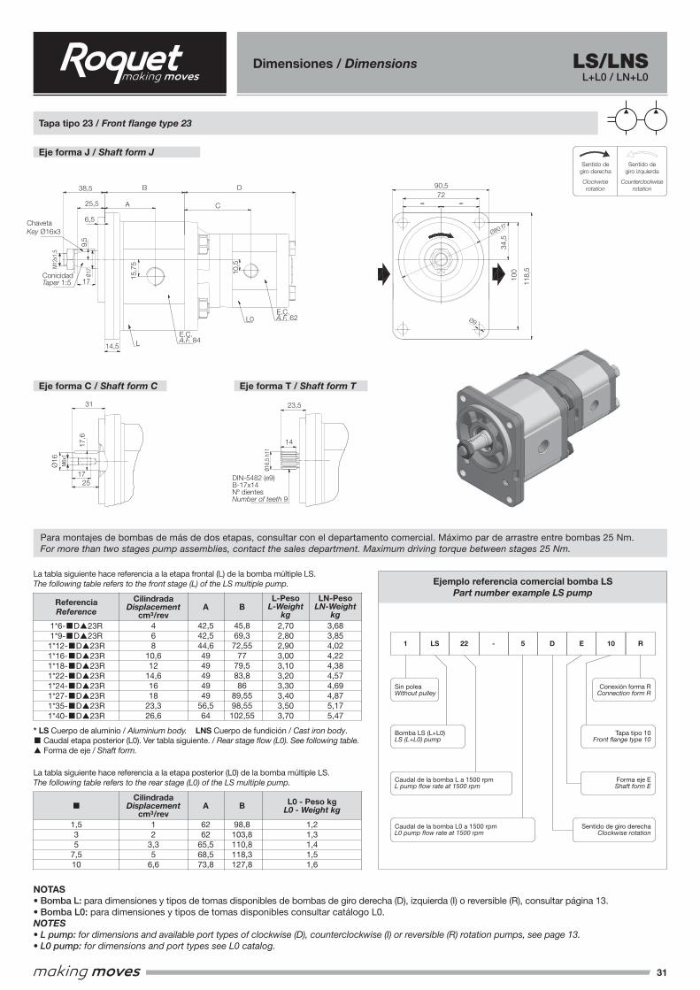
31
15,7
5
10,5
A
B
C
D9,
5
17
17
38,5
25,5
6,5
M12x
1.5
80 f7
34,5
100
72
= =
118,
5
90,5
9
Eje forma T / Shaft form TEje forma C / Shaft form C
25
17
M6x1
16
17,6
31
DIN-5482 (e9)B-17x14
Nº dientesNumber of teeth 9
16,5
h11
23,5
14
ConicidadTaper 1:5
Chaveta Key Ø16x3
14,5
E.C.A.F. 84
E.C.A.F. 62
Eje forma J / Shaft form JTapa tipo 23 / Front flange type 23
L
L0
Eje forma J / Shaft form J
Eje forma C / Shaft form C Eje forma T / Shaft form T
Sentido de giro derechaClockwise rotation
Sentido de giro izquierdaCounterclockwise rotation
Sentido de giro reversibleReversible rotation
IMATGE 1
IMATGE 2
Sentido de giro derechaClockwise rotation
Sentido de giro izquierdaCounterclockwise rotation
Sentido de giro reversibleReversible rotation
IMATGE 1
IMATGE 2
Sentido degiro derecha
Clockwiserotation
Sentido degiro izquierda
Counterclockwise rotation
LS/LNSL+L0 / LN+L0
Tapa tipo 23 / Front flange type 23
Para montajes de bombas de más de dos etapas, consultar con el departamento comercial. Máximo par de arrastre entre bombas 25 Nm.For more than two stages pump assemblies, contact the sales department. Maximum driving torque between stages 25 Nm.
La tabla siguiente hace referencia a la etapa posterior (L0) de la bomba múltiple LS.The following table refers to the rear stage (L0) of the LS multiple pump.
La tabla siguiente hace referencia a la etapa frontal (L) de la bomba múltiple LS.The following table refers to the front stage (L) of the LS multiple pump.
* LS Cuerpo de aluminio / Aluminium body. LNS Cuerpo de fundición / Cast iron body.■ Caudal etapa posterior (L0). Ver tabla siguiente. / Rear stage flow (L0). See following table.▲ Forma de eje / Shaft form.
Ejemplo referencia comercial bomba LSPart number example LS pump
Sin poleaWithout pulley
Bomba LS (L+L0)LS (L+L0) pump
Caudal de la bomba L a 1500 rpmL pump flow rate at 1500 rpm
Caudal de la bomba L0 a 1500 rpmL0 pump flow rate at 1500 rpm
Sentido de giro derechaClockwise rotation
Conexión forma RConnection form R
1 LS 22 - 5 D E 10 R
Tapa tipo 10Front flange type 10
Forma eje EShaft form E
1,535
7,510
Dimensiones / Dimensions
1*6-■D▲23R1*9-■D▲23R1*12-■D▲23R1*16-■D▲23R1*18-■D▲23R1*22-■D▲23R1*24-■D▲23R1*27-■D▲23R1*35-■D▲23R1*40-■D▲23R
468
10,612
14,61618
23,326,6
L-PesoL-Weight
kg
LN-PesoLN-Weight
kg2,702,802,903,003,103,203,303,403,503,70
3,683,854,024,224,384,574,694,875,175,47
A
42,542,544,64949494949
56,564
B
45,869,372,55
7779,583,886
89,5598,55102,55
CilindradaDisplacement
cm³/rev
ReferenciaReference
12
3,35
6,6
L0 - Peso kgL0 - Weight kg
1,21,31,41,51,6
A
6262
65,568,573,8
B
98,8103,8110,8118,3127,8
CilindradaDisplacement
cm³/rev■
NOTAS • Bomba L: para dimensiones y tipos de tomas disponibles de bombas de giro derecha (D), izquierda (I) o reversible (R), consultar página 13. • Bomba L0: para dimensiones y tipos de tomas disponibles consultar catálogo L0.NOTES • L pump: for dimensions and available port types of clockwise (D), counterclockwise (I) or reversible (R) rotation pumps, see page 13. • L0 pump: for dimensions and port types see L0 catalog.
15,7
5
10,5
A
B
C
D
9,5
17
17
38,5
25,5
6,5
M12x
1.5
80 f7
34,5
100
72
= =
118,
5
90,5
9
Eje forma T / Shaft form TEje forma C / Shaft form C
25
17
M6x1
16
17,6
31
DIN-5482 (e9)B-17x14
Nº dientesNumber of teeth 9
16,5
h11
23,5
14
ConicidadTaper 1:5
Chaveta Key Ø16x3
14,5
E.C.A.F. 84
E.C.A.F. 62
Eje forma J / Shaft form JTapa tipo 23 / Front flange type 23
L
L0
100
34,5
ChavetaKey Ø16x3
15,7
5
Ø16
17,6
9,5
10,5M12
x1,5
M6x
1
Ø16,
5 h1
1
Ø17
118,
5
25,5
14,5
6,5
38,5
31 23,5
17
14
25
L
L0
B D
CA
17
7290,5
= =
ConicidadTaper 1:5
DIN-5482 (e9)B-17x14Nº dientesNumber of teeth 9
E.C.A.F. 84
E.C.A.F. 62 Ø9
Ø80 f7
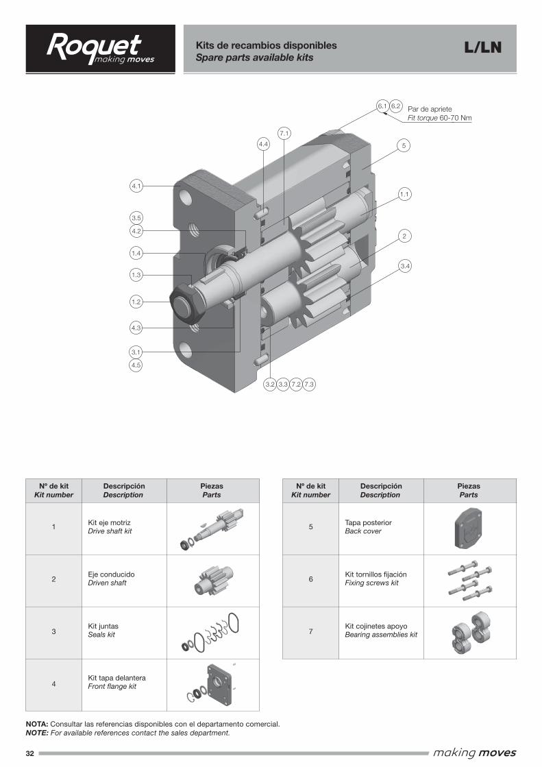
32
Descripción Description
Descripción Description
Kit eje motriz Drive shaft kit
Eje conducido Driven shaft
Kit juntas Seals kit
Kit tapa delantera Front flange kit
Tapa posterior Back cover
Kit tornillos fijación Fixing screws kit
Kit cojinetes apoyo Bearing assemblies kit
1
2
3
4
5
6
7
Piezas Parts
Piezas Parts
Nº de kit Kit number
Nº de kit Kit number
NOTA: Consultar las referencias disponibles con el departamento comercial.NOTE: For available references contact the sales department.
Kits de recambios disponiblesSpare parts available kits
L/LN
1.2
1.4
1.3
4.1
6.1 6.2
5
1.1
2
3.2 3.3 7.2 7.3
7.1
3.4
4.4
4.3
3.1
4.5
4.2
3.5
Par de aprieteFit torque 60-70NmPar de aprieteFit torque 60-70 Nm
6.2
5
1.1
2
3.4
6.1
7.1
4.4
4.1
3.5
4.2
1.4
1.3
1.2
4.3
3.1
4.5
3.2 3.3 7.2 7.3
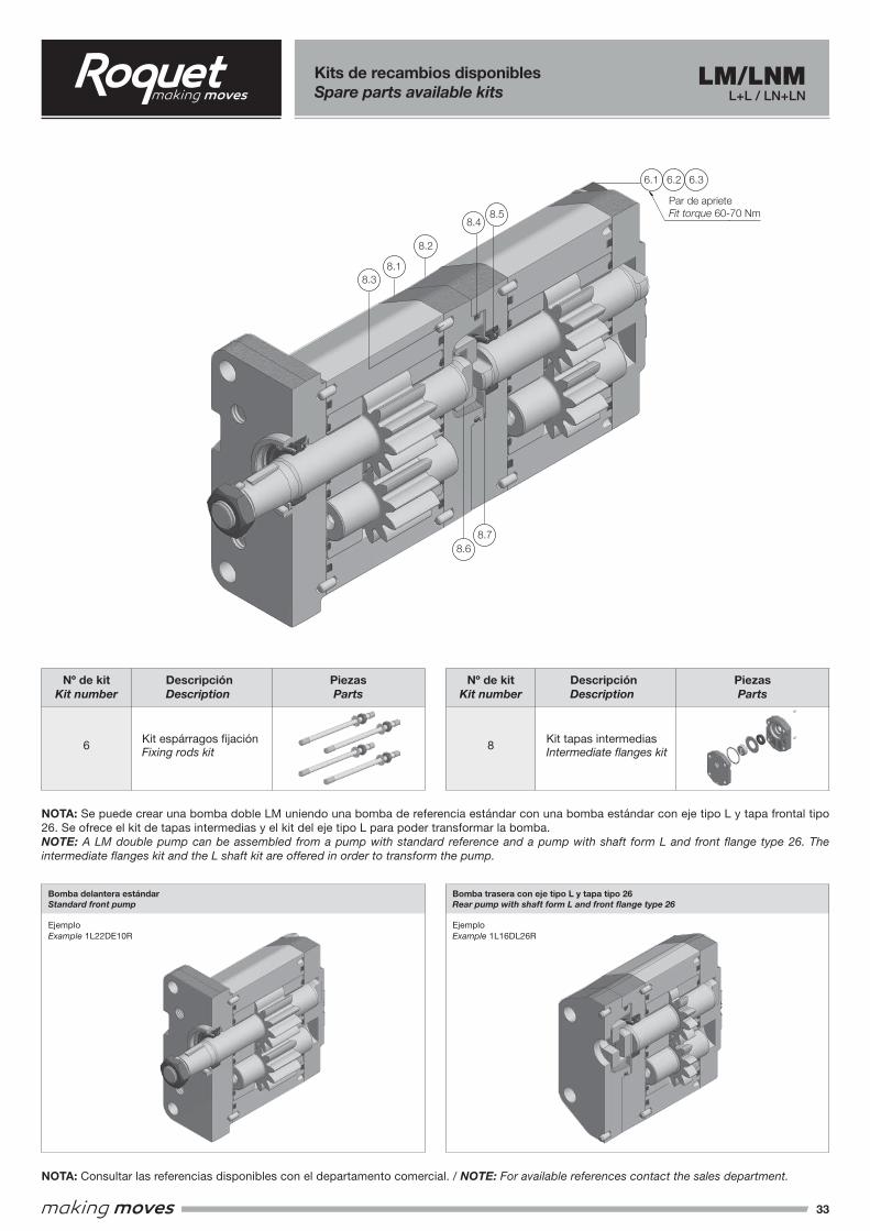
33
Kits de recambios disponiblesSpare parts available kits
Descripción Description
Descripción Description
Kit espárragos fijación Fixing rods kit
Kit tapas intermedias Intermediate flanges kit6 8
Piezas Parts
Piezas Parts
Nº de kit Kit number
Nº de kit Kit number
NOTA: Consultar las referencias disponibles con el departamento comercial. / NOTE: For available references contact the sales department.
NOTA: Se puede crear una bomba doble LM uniendo una bomba de referencia estándar con una bomba estándar con eje tipo L y tapa frontal tipo 26. Se ofrece el kit de tapas intermedias y el kit del eje tipo L para poder transformar la bomba.NOTE: A LM double pump can be assembled from a pump with standard reference and a pump with shaft form L and front flange type 26. The intermediate flanges kit and the L shaft kit are offered in order to transform the pump.
Bomba delantera estándarStandard front pump
Bomba trasera con eje tipo L y tapa tipo 26Rear pump with shaft form L and front flange type 26
EjemploExample 1L22DE10R
EjemploExample 1L16DL26R
LM/LNML+L / LN+LN
6.1 6.2 6.3
8.58.4
8.2
8.18.3
Par de aprieteFit torque 60-70 Nm
8.68.7
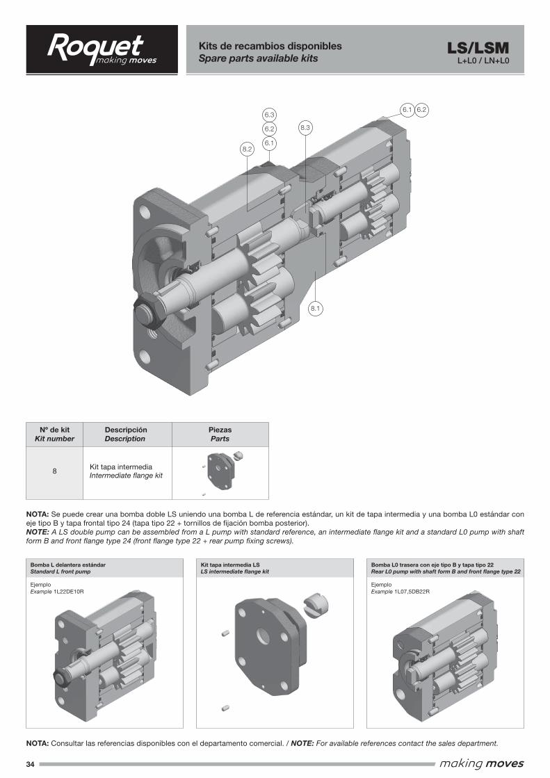
34
Kits de recambios disponiblesSpare parts available kits
Descripción Description
Kit tapa intermedia Intermediate flange kit8
Piezas Parts
Nº de kit Kit number
NOTA: Consultar las referencias disponibles con el departamento comercial. / NOTE: For available references contact the sales department.
LS/LSML+L0 / LN+L0
NOTA: Se puede crear una bomba doble LS uniendo una bomba L de referencia estándar, un kit de tapa intermedia y una bomba L0 estándar con eje tipo B y tapa frontal tipo 24 (tapa tipo 22 + tornillos de fijación bomba posterior).NOTE: A LS double pump can be assembled from a L pump with standard reference, an intermediate flange kit and a standard L0 pump with shaft form B and front flange type 24 (front flange type 22 + rear pump fixing screws).
Bomba L delantera estándarStandard L front pump
Kit tapa intermedia LSLS intermediate flange kit
Bomba L0 trasera con eje tipo B y tapa tipo 22Rear L0 pump with shaft form B and front flange type 22
EjemploExample 1L22DE10R
EjemploExample 1L07,5DB22R
6.1
6.1
6.2
6.3
8.3
8.2
6.2
8.1


www.roquetgroup.com
BI.02.03.03/07.17