Embed Size (px)
Citation preview
Engineering Electronics Power Drives and Generator (AE / EEG1)
Internship PresentationGeeth Prajwal Reddy Putchakayala
M.Sc. Electrical Power Engineering
Rheinisch- Westfälische Technische Hochschule Aachen
Matrikel No. 340998
Supervisors
Mr. Zoltan Ersek Dr. Paul Mehringer
Engineering Electronics Power Drives and Generator (AE / EEG1)
Company Profile
Development, production and sale of microelectronic products for
automotive and non-automotive applications. Core competencies are system
integration and application engineering for automobiles
Robert Bosch GmbH – Automotive Electronics Division
Areas of operation
• Electronic Control Units (ECUs)
• Contract manufacture of ECUs
• Body electronics and ECU components
• Power electronics and modules
• Mechatronic modules for electric power steering
• Semiconductors
• Sensors
• eBike systems
Headquarters : Reutlingen, Stuttgart
Engineering Electronics Power Drives and Generator (AE / EEG1)
Objective of Internship
The objective of the internship is to develop a control
strategy for the torque control of an electrically excited five
phase synchronous machine without using PWM. The
control strategy should also be able to operate the machine
from 0 RPM to high speeds and must also be able to limit
the high starting currents in the phase windings of the
machine.
The object for the investigation into the use of block
commutation is to reduce the size of the DC link capacitance
required by avoiding the use of Field Oriented Control (FOC)
at low speed.
Internship Presentation
Engineering Electronics Power Drives and Generator (AE / EEG1)
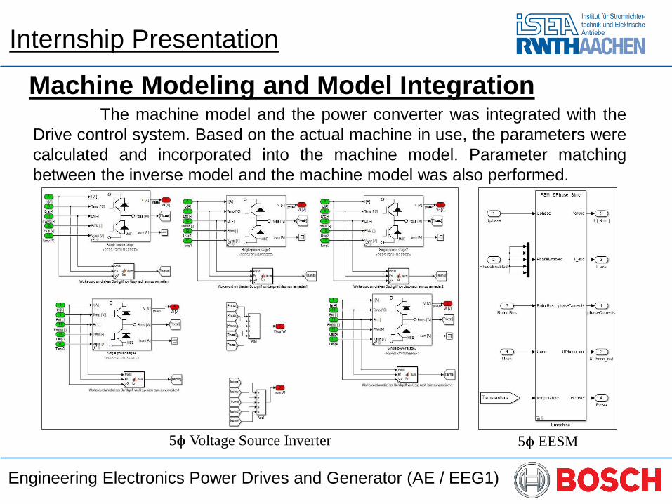
Machine Modeling and Model IntegrationThe machine model and the power converter was integrated with the
Drive control system. Based on the actual machine in use, the parameters were
calculated and incorporated into the machine model. Parameter matching
between the inverse model and the machine model was also performed.
5ϕ Voltage Source Inverter 5ϕ EESM
Internship Presentation
Engineering Electronics Power Drives and Generator (AE / EEG1)
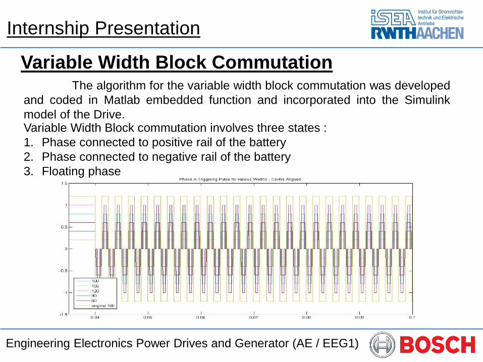
Variable Width Block CommutationThe algorithm for the variable width block commutation was developed
and coded in Matlab embedded function and incorporated into the Simulink
model of the Drive.Variable Width Block commutation involves three states :
1. Phase connected to positive rail of the battery
2. Phase connected to negative rail of the battery
3. Floating phase
Internship Presentation
Engineering Electronics Power Drives and Generator (AE / EEG1)
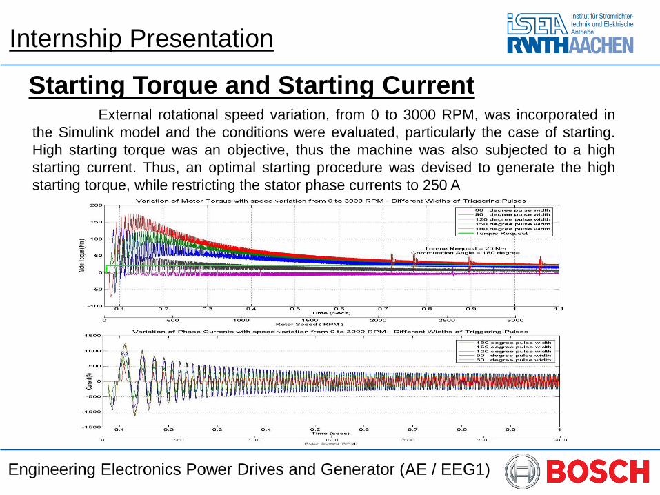
Starting Torque and Starting CurrentExternal rotational speed variation, from 0 to 3000 RPM, was incorporated in
the Simulink model and the conditions were evaluated, particularly the case of starting.
High starting torque was an objective, thus the machine was also subjected to a high
starting current. Thus, an optimal starting procedure was devised to generate the high
starting torque, while restricting the stator phase currents to 250 A
Internship Presentation
Engineering Electronics Power Drives and Generator (AE / EEG1)
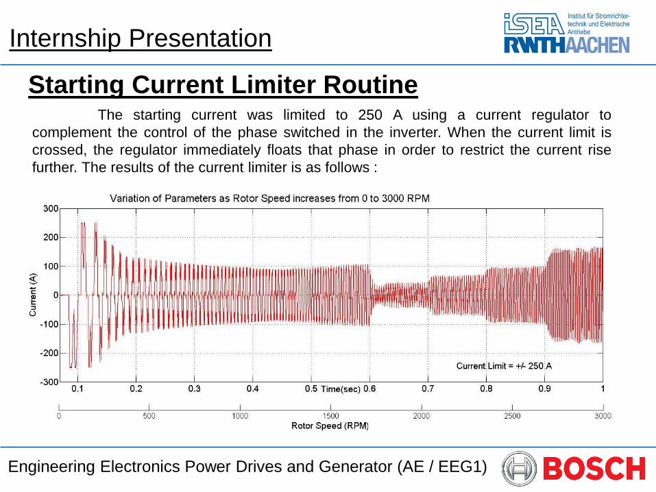
Starting Current Limiter RoutineThe starting current was limited to 250 A using a current regulator to
complement the control of the phase switched in the inverter. When the current limit is
crossed, the regulator immediately floats that phase in order to restrict the current rise
further. The results of the current limiter is as follows :
Internship Presentation
Engineering Electronics Power Drives and Generator (AE / EEG1)
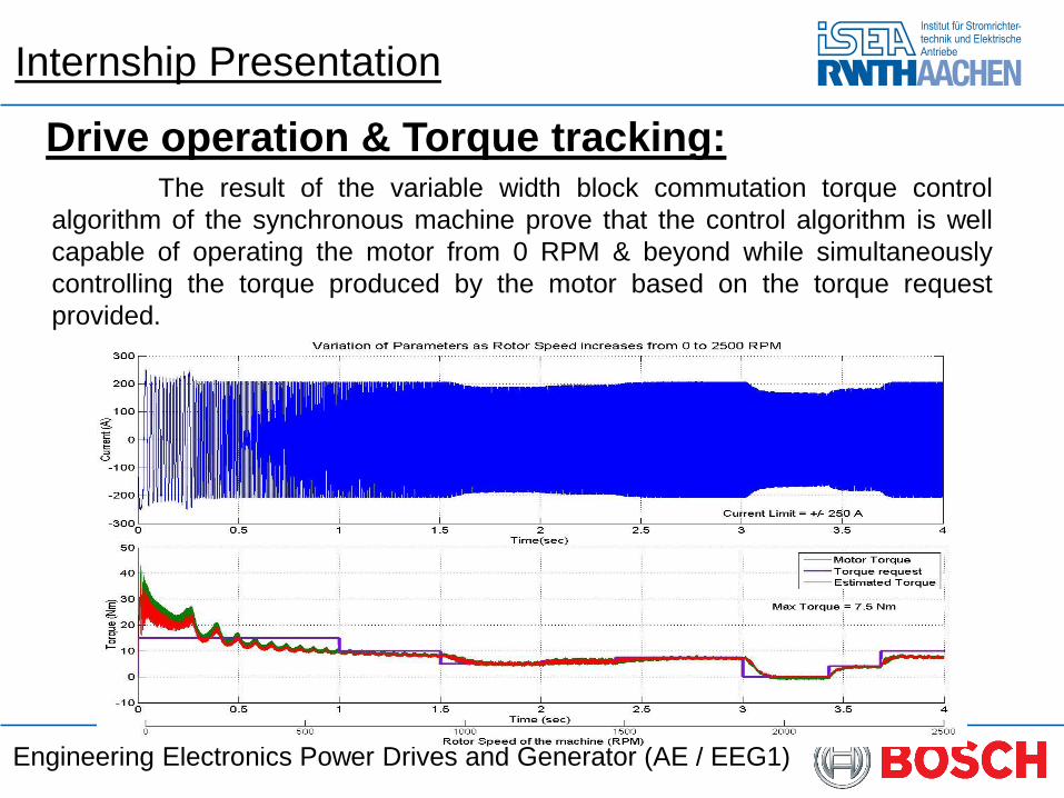
Drive operation & Torque tracking:The result of the variable width block commutation torque control
algorithm of the synchronous machine prove that the control algorithm is well
capable of operating the motor from 0 RPM & beyond while simultaneously
controlling the torque produced by the motor based on the torque request
provided.
Internship Presentation
Engineering Electronics Power Drives and Generator (AE / EEG1)
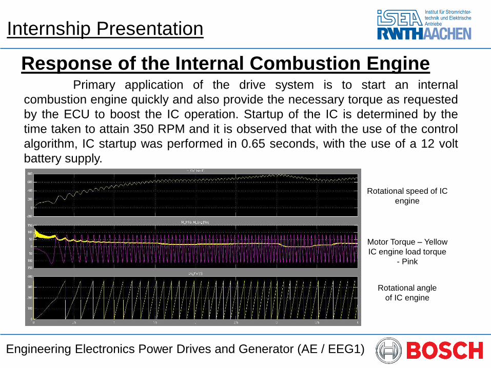
Response of the Internal Combustion EnginePrimary application of the drive system is to start an internal
combustion engine quickly and also provide the necessary torque as requested
by the ECU to boost the IC operation. Startup of the IC is determined by the
time taken to attain 350 RPM and it is observed that with the use of the control
algorithm, IC startup was performed in 0.65 seconds, with the use of a 12 volt
battery supply.
Rotational speed of IC
engine
Motor Torque – Yellow
IC engine load torque
- Pink
Rotational angle
of IC engine
Internship Presentation
Engineering Electronics Power Drives and Generator (AE / EEG1)
Hardware Implementation of the Drive system
Hardware implementation and testing involved five major steps :
1. Porting of Matlab Simulink model control algorithm to dSPACE Rapid
prototyping.
2. Design of dSPACE ControlDesk GUI for drive control.
3. Design of a driver circuit to trigger the switches of the five phase VSI
4. Assembly and interfacing of the driver, inverter and machine with the
dSPACE system.
5. Preparation of the test bench and interfacing the connections of the
measurement and the supply systems with the drive system and their
calibration.
Internship Presentation
Engineering Electronics Power Drives and Generator (AE / EEG1)
Porting to dSPACEThe control algorithm is ported into the dSPACE system using the Matlab
Simulink blocks, Xilinx Toolbox and the RTI programming blocks. The control algorithm
is split up to operate between the DS1005 FPGA and microcontroller in the dSPACE
system.
The FPGA, operating at 10 ns, includes the following functionalities :
• Input interface: Reads data from the measurement sensors and translates them to
appropriate current ad voltage values using the ADCs onboard the FPGA.
• Monitoring system: Monitors the voltage and current parameters of the drive and
shuts down the system incase of error.
• Current Limiter: Implements the phase current regulation function
• IdleState: Idle state is one of the states of the machine during which the all low side
switches of the VSI are turned ON to charge the Bootstrap capacitances of the drive
• Dead Time: Software code to implement variable deadtime among the switches in
each phase leg of the VSI.
• Output Interface: Generates the gating pattern signals to the driver circuit, through
the Digital_I/O ports of the FPGA, from the timing data calculated by the control
algorithm in the microcontroller.
Internship Presentation
Engineering Electronics Power Drives and Generator (AE / EEG1)
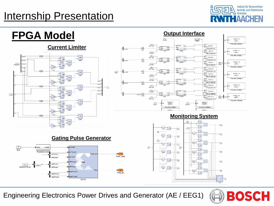
FPGA Model
Monitoring System
Current Limiter
Gating Pulse Generator
Output Interface
Internship Presentation
Engineering Electronics Power Drives and Generator (AE / EEG1)
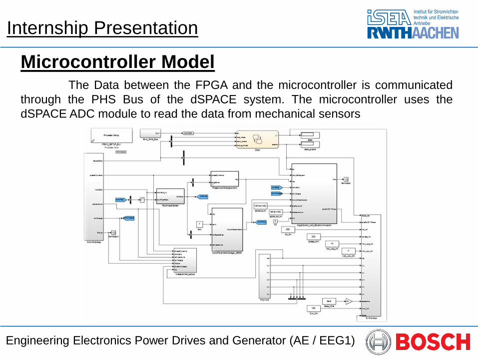
Microcontroller ModelThe Data between the FPGA and the microcontroller is communicated
through the PHS Bus of the dSPACE system. The microcontroller uses the
dSPACE ADC module to read the data from mechanical sensors
Internship Presentation
Engineering Electronics Power Drives and Generator (AE / EEG1)
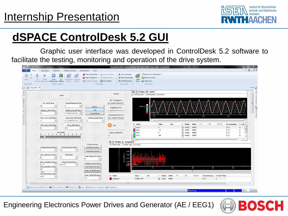
dSPACE ControlDesk 5.2 GUIGraphic user interface was developed in ControlDesk 5.2 software to
facilitate the testing, monitoring and operation of the drive system.
Internship Presentation
Engineering Electronics Power Drives and Generator (AE / EEG1)
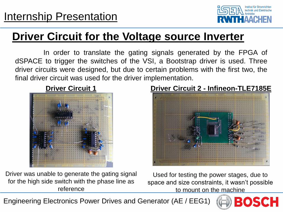
Driver Circuit for the Voltage source Inverter
In order to translate the gating signals generated by the FPGA of
dSPACE to trigger the switches of the VSI, a Bootstrap driver is used. Three
driver circuits were designed, but due to certain problems with the first two, the
final driver circuit was used for the driver implementation.
Internship Presentation
Driver Circuit 1
Driver was unable to generate the gating signal
for the high side switch with the phase line as
reference
Driver Circuit 2 - Infineon-TLE7185E
Used for testing the power stages, due to
space and size constraints, it wasn’t possible
to mount on the machine
Engineering Electronics Power Drives and Generator (AE / EEG1)
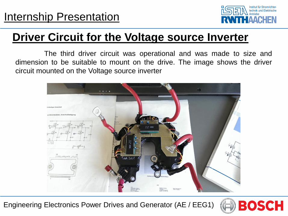
Driver Circuit for the Voltage source Inverter
The third driver circuit was operational and was made to size and
dimension to be suitable to mount on the drive. The image shows the driver
circuit mounted on the Voltage source inverter
Internship Presentation
Engineering Electronics Power Drives and Generator (AE / EEG1)
Integration to Test Bench
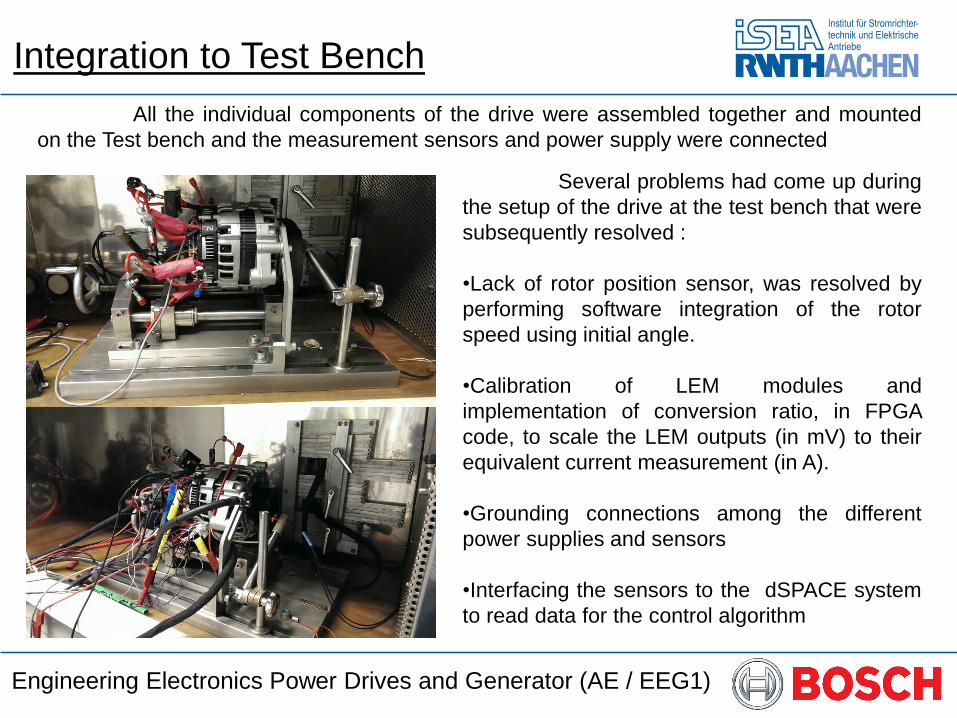
All the individual components of the drive were assembled together and mounted
on the Test bench and the measurement sensors and power supply were connected
Several problems had come up during
the setup of the drive at the test bench that were
subsequently resolved :
•Lack of rotor position sensor, was resolved by
performing software integration of the rotor
speed using initial angle.
•Calibration of LEM modules and
implementation of conversion ratio, in FPGA
code, to scale the LEM outputs (in mV) to their
equivalent current measurement (in A).
•Grounding connections among the different
power supplies and sensors
•Interfacing the sensors to the dSPACE system
to read data for the control algorithm
Engineering Electronics Power Drives and Generator (AE / EEG1)
Drive Operation
With all the problems resolved, all the monitoring and safety systems
were verified and measures were taken to prevent overvoltage spikes due to the
connecting cables, with the use of Zener Diode.
Finally the Drive was turned ON and it was observed that despite small
glitches in the starting operation and mild toggling of the rotor, the synchronous
motor was in fact operational with the use of variable width block commutation
algorithm even for low speed operations .
The toggling of the rotor was caused due to the improper connection of
the phase windings to the appropriate phase legs of the VSI due to improper
marking of the phase windings on the machine. This problem was resolved by
operating the machine as an alternator and from the observation of the current
waveforms induced in the stator phase winding, the correct phases were identified
and the reconnected correctly.
Engineering Electronics Power Drives and Generator (AE / EEG1)