Embed Size (px)
Citation preview

Engineering Fracture Mechanics 102 (2013) 51–64
Contents lists available at SciVerse ScienceDirect
Engineering Fracture Mechanics
journal homepage: www.elsevier .com/locate /engfracmech
An XFEM crack-tip enrichment for a crack terminating at abi-material interface
0013-7944/$ - see front matter � 2013 Elsevier Ltd. All rights reserved.http://dx.doi.org/10.1016/j.engfracmech.2013.02.023
⇑ Corresponding author. Tel.: +352 425 991 4574; fax: +352 425 991 555.E-mail address: [email protected] (L. Bouhala).
L. Bouhala a,⇑, Q. Shao a,b, Y. Koutsawa a, A. Younes b, P. Núñez c, A. Makradi a, S. Belouettar a
a Centre de Recherche Public Henri Tudor, 29, Avenue John F. Kennedy, L-1855 Luxembourg-Kirchberg, Luxembourgb Laboratoire d’Hydrologie et de Géochimie de Strasbourg, Université de Strasbourg/EOST, CNRS, 1 rue Blessig, 67084 Strasbourg, Francec Departamento de Quı́mica Inorgánica, Universidad de La Laguna, 38200-La Laguna, Tenerife, Spain
a r t i c l e i n f o a b s t r a c t
Article history:Received 25 July 2012Received in revised form 12 February 2013Accepted 18 February 2013
Keywords:Crack tip singularityXFEMSIFCharacteristic exponentsEnrichment functions
Crack-tip enrichment functions are determined for a crack terminating at a bi-materialinterface. The stress and displacement components at the crack-tip are expressed consid-ering plane elasticity solution based on Airy functions. The crack-tip characteristic expo-nents and the enrichment functions are determined using the problem boundaryconditions. Single real, double real or complex characteristic exponents are found depend-ing on the crack-angle and the relative mechanical properties of the considered bi-material.Crack-tip enrichment functions are determined for cases where the characteristic exponentis real and complex. To validate the efficiency of the enrichment functions at the crack-tipsingularity, the eXtended Finite Element Method (XFEM) is used to solve a mode-I crackterminating at the bi-material interface. Thanks to two Level-set functions, the crack andthe bi-material interface are located and the nodes belonging to elements cut by these dis-continuities are enriched. The Stress Intensity Factors (SIF) are calculated for a crack per-pendicular and terminating at the bi-material interface using the body force method(BFM). The implemented method was tested and good agreement is found when comparedto other investigations in the literature.
� 2013 Elsevier Ltd. All rights reserved.
1. Introduction
The development of the extended finite element method (XFEM) and the Meshless numerical methods gave new insighton dealing with discontinuities in solid materials, without any needs of re-meshing at the discontinuity but by only usingappropriate enrichment functions. This concept was first introduced by Fix and co-authors [1,2] to deal with finite elementconvergence in presence of singularities. Since then different type of enrichment functions were developed to enforce thediscontinuity of fields and/or discontinuity of field derivatives [3–8]. In application, for instance these enrichment functionsare used to describe the discontinuity of the displacement and the discontinuity of its displacement derivatives through a bi-material interface. In case of cracked materials, the discontinuity of the displacement through the crack is represented byusing either the sign function or the Heaviside function. However, additional enrichment functions are needed to describethe stress singularity at the crack tip. These kinds of enrichment functions can be determined from the asymptotic solutionsof the displacement in the vicinity of the crack tip. In case of crack within a pure homogenous elastic material, the near cracktip displacement and stress are of the form ðrij � r�k;ui � r1�kÞ. The characteristic exponent (k) is a real value equal to 0.5,and the near tip enrichment functions are given by rksin (h/2), rkcos (h/2), rksin (h/2) sin (h) and rkcos (h/2) sin (h). XFEM con-vergence analysis of an enriched crack tip in a homogeneous elastic material can be found in the work of Laborde et al. [9]

Nomenclature
Ai XFEM nodal displacement unknowns at the crick-tipE1, E2 Young’s modulusNI shape functionsu crack-tip asymptotic displacementU XFEM displacementuI XFEM nodal displacement unknownsuc
I XFEM nodal displacement unknowns at the crack surfaceW, Wb, Wc, Wtip integration domainsx point coordinatesa, b Dundurs parametersf crack angler, h polar coordinatesk crack-tip characteristic exponentskR, kI real and imaginary parts of the crack-tip characteristic exponentl shear modulusm Poisson’s ratiorij stresses/, w Airy functions/c, /i level set functionsuk crack-tip enrichment functions
52 L. Bouhala et al. / Engineering Fracture Mechanics 102 (2013) 51–64
and Béchet et al. [10]. Chahine et al. [11] and Nicaise et al. [12] proposed other variant of enrichment methods for crack tipsingularities in homogeneous elastic materials, where a cutoff function was used to enrich the crack tip area. In case of acrack terminating at a bi-material interface (see Fig. 1), the characteristic exponent (k) can be real single, real double or com-plex depending on the mismatch between the two materials and the angle (f) between the crack and the interface [13–15].Further, the corresponding analytical asymptotic displacement solution in the vicinity of the crack tip, that is needed to deter-mine the enrichment functions, is also dependent on the material properties and the crack angle (f). Not that, the crack-tipenrichment functions can also determined numerically based on the asymptotic displacement solution at the crack-tip[16]. Based on the work of Li et al. [16], numerical enrichment functions are used recently in conjunction with the XFEMby Menk and Bordas [17,18] to enrich bi-material crack tip and polycrystal grains junction.
Crack terminating at a bi-material interface with an oblique angle can be found in engineering application such as het-erogeneous composites, where the distribution and orientation of the fillers is complex. In such composites, the multipleinteraction of the crack-tip with the fillers can lead to the case of a crack terminating at filler/matrix interface with an ob-lique angle [19]. Study of this kind of cracks is reported by several authors, see for instance [20–22]. However, their exploi-tation to feed the well-established XFEM and mesh free numerical methods with appropriate crack tip enrichment functionsis still not clear.
The present paper focuses on the determination of enrichment functions for crack terminating at a bi-material interface.The crack-tip singularity formulation and crack-tip enrichment functions are recalled in Section 2. In Section 3, the XFEM is
Fig. 1. Crack terminating on bi-material interface.

L. Bouhala et al. / Engineering Fracture Mechanics 102 (2013) 51–64 53
implemented and effects of the crack-tip enrichment functions on rate of convergence are investigated. For validation, theStress Intensity Factors are calculated for a crack perpendicular to the bi-material interface and compared with ones from theliterature in Section 4.
2. Crack tip singularity formulation
In the absence of body forces the stress and displacement solution of plane elasticity governing equations can be ex-pressed in terms of the Airy functions uj(r,h) as follow:
rjr ¼ r�2/jðr; hÞ;hh þ r�1/jðr; hÞ;r ; ð1Þ
rjh ¼ /jðr; hÞ;rr ; ð2Þ
rjrh ¼ �ðr�1/jðr; hÞ;hÞ;r ; ð3Þ
2ljujr ¼ �/jðr; hÞ;r þ ð1� mjÞrwjðr; hÞ;h; ð4Þ
2ljujh ¼ �r�1/jðr; hÞ;h þ ð1� mjÞr2wjðr; hÞ;r; ð5Þ
where j, (j = 1, 2, 3) indicates the regions as reported in Fig. 1, and the functions /j and wj are related by: r2/ = (rw,h),r.The solution of the Airy functions in Eqs. (1)–(5) depends on the crack angle f as well as the material properties at the
vicinity of the crack tip. These functions are determined following the Williams’s approach [23,24] considering a parametricsolution (Eq. (8)) whose parameters are determined using the problem boundary conditions. In case of crack terminating at abi-material interface, the boundary conditions describing the continuity at the bi-material interface and the traction freecrack faces are given by:
Continuity boundary conditions at the bi-material interface:
r1h ðr; h ¼ 0Þ ¼ r3
hðr; h ¼ 0Þ; ð6:aÞ
r2h ðr; h ¼ pÞ ¼ r3
h ðr; h ¼ pÞ; ð6:bÞ
r1rhðr; h ¼ 0Þ ¼ r3
rhðr; h ¼ 0Þ; ð6:cÞ
r2rhðr; h ¼ pÞ ¼ r3
hðr; h ¼ pÞ; ð6:dÞ
u1r ðr; h ¼ 0Þ ¼ u3
r ðr; h ¼ 0Þ; ð6:eÞ
u2r ðr; h ¼ pÞ ¼ u3
r ðr; h ¼ pÞ; ð6:fÞ
u1hðr; h ¼ 0Þ ¼ u3
hðr; h ¼ 0Þ; ð6:gÞ
u2hðr; h ¼ pÞ ¼ u3
h ðr; h ¼ pÞ; ð6:hÞ
Traction free boundaries at the crack surfaces:
r1h ðr; h ¼ �fÞ ¼ 0; ð6:iÞ
r2h ðr; h ¼ 2p� fÞ ¼ 0; ð6:jÞ
r1rhðr; h ¼ �fÞ ¼ 0; ð6:kÞ
r2rhðr; h ¼ 2p� fÞ ¼ 0; ð6:lÞ
Here (r,h) are the polar coordinates at the crack tip (see Fig. 1). Depending on the crack angle (f) and the mismatch of the bi-material mechanical properties, the resulted characteristic exponents (kk) could be real single (kk,k = 1), real double(kk,k = 1,2) or complex (k1 = kR + ikI,k2 = kR � ikI), where kR and kI are the real and imaginary components of the complex val-ues and i ¼
ffiffiffiffiffiffiffi�1p
. The Airy functions, /j (r,h), can be defined as a superposition of different terms, where each term verifiesthe Eqs. (1)–(6).
/jðr; hÞ ¼X
k
rðkkþ1ÞFkj ðhÞ ð7Þ
where
Fkj ðhÞ ¼ ak
j sinðkþ 1Þhþ bkj cosðkþ 1Þhþ ck
j sinðk� 1Þhþ dkj cosðk� 1Þh ð8Þ
On what follows, only one term of the Airy functions /j (r,h) will be considered for solving the system of Eqs. (1)–(8), thenthe final solution can be found by superposition of the individual solutions. Therefore considering only one term and ignor-ing the superscript (k = 1), Eqs. (7) and (8) become:
/jðr; hÞ ¼ rkþ1FjðhÞ ð9ÞFjðhÞ ¼ aj sinðkþ 1Þhþ bj cosðkþ 1Þhþ cj sinðk� 1Þhþ dj cosðk� 1Þh ð10Þ

54 L. Bouhala et al. / Engineering Fracture Mechanics 102 (2013) 51–64
Substituting Eq. (9) into Eqs. (1)–(5), the stresses and displacement components are given by:
rjr ¼ rðk�1ÞðF 00j ðhÞ þ ðkþ 1ÞFjðhÞÞ ð11Þ
rjh ¼ ðkþ 1Þkrðk�1ÞFjðhÞ ð12Þ
rjrh ¼ �krðk�1ÞF 0jðhÞ ð13Þ
2ljujr ¼ k�1rk½ð�kðkþ 1Þ þ ð1� mjÞð1þ kÞ2ÞFjðhÞ þ ð1� mÞF 00j ðhÞ� ð14Þ
2ljujh ¼ rk �F 0jðhÞ þ k�1ð1� mjÞðk� 1Þ F 0jðhÞ þ ðkþ 1Þ2ð�ajðkþ 1Þ�1 cosðkþ 1Þhþ bjðkþ 1Þ�1 sinðkþ 1Þh
�h�cjðk� 1Þ�1 cosðk� 1Þhþ cjðk� 1Þ�1 sinðk� 1ÞhÞ
�ið15Þ
Here F 0j and F 00j are, respectively, the first and the second derivatives of the function Fj relative to h. The details on the deri-vation of the displacement components (Eqs. (14) and (15)) are given in Appendix A.
To determine the characteristic exponent (k), Eqs. (9) and (10) are substituted into Eqs. (11)–(15), then the boundary con-ditions (6) are written as function of (k,aj,bj,cj,dj,j = 1,2,3). The resulted system of twelve algebraic linear equations ðRx ¼ 0Þ isgiven in Appendix B, where the vector (x) contains the unknowns (aj,bj,cj,dj, j = 1, 2, 3). For nontrivial solution, the determi-nant of the matrix ðRÞ must be equal to zero. Therefore the characteristic exponent solution (k) is calculated numericallyusing a MATLAB iterative solver: fsolve, by solving the following equation,
ðdetðRÞ ¼ 0Þ ð16Þ
2.1. Characteristic exponent k
For the investigation of the characteristic exponent’s dependence on the crack angle (f) and on the bi-material mechanicalproperties mismatch, the crack is considered lying in the material-1 and terminating at the interface between the two mate-rials (see Fig. 1).
Fig. 2 shows the dependence of the characteristic exponent on crack angle (f) and the mechanical mismatch through thebi-material interface. The characteristic exponent is real single in case of a crack perpendicular to the interface then becomesreal double once the crack is oblique. Once the crack goes to zero or to p the characteristic exponent becomes complex. Thepassage from real double to complex values depends on both the crack angle (f) and the mechanical mismatch (E2/E1). Ar-rows on Fig. 3 show the value of (E2/E1) at which the real double value of k becomes complex for each crack angle.
2.2. Enrichment functions
Substituting Eq. (10) and its derivatives into Eqs. (14) and (15), the displacement components in polar coordinates writes:
Fig. 2. Characteristic exponents’ (k1,k2) vs E2/E1 for different crack angles.

Fig. 3. Re{k1}, Re{k2} vs E2/E1; arrows indicate the passage from real to complex values of the characteristic exponents.
L. Bouhala et al. / Engineering Fracture Mechanics 102 (2013) 51–64 55
ujr ¼
rk
2lj½�ajðkþ 1Þ sinðkþ 1Þh� bjðkþ 1Þ cosðkþ 1Þhþ cjð3� k� 4mÞ sinðk� 1Þhþ djð3� k� 4mÞ cosðk� 1Þh� ð17Þ
ujh ¼
rk
2lj½�ajðkþ 1Þcosðkþ 1Þhþ bjðkþ 1Þ sinðkþ 1Þhþ cjð�3� kþ 4mÞ cosðk� 1Þhþ djð3þ k� 4mÞ sinðk� 1Þh� ð18Þ
On what follows, the enrichment functions will be deduced from Eqs. (17) and (18) by considering separately the casewhere the characteristic exponent (k) is real and the case where it is complex.
2.2.1. Real characteristic exponentCombining the terms of Eqs. (17) and (18), the displacement components (ur,uh) can be rearranged as follow:
ur ¼X
k
Ak1
� �rrkk cosðkk þ 1Þhþ Ak
2
� �rrkk sinðkk þ 1Þhþ Ak
3
� �rrkk cosðkk � 1Þhþ Ak
4
� �rrkk sinðkk � 1Þh
uh ¼X
k
Ak1
� �hrkk cosðkk þ 1Þhþ Ak
2
� �hrkk sinðkk þ 1Þhþ Ak
3
� �hrkk cosðkk � 1Þhþ Ak
4
� �hrkk sinðkk � 1Þh;
ð19Þ
where ðAki¼1...:4Þr;h are constants for a given characteristic exponent (k) and bi-material mechanical properties. These constants
do not need to be determined analytically since in XFEM and meshless methods analysis they are considered as unknownsand calculated numerically. In Eq. (19), k is the number of the characteristic exponents: k = 1 in case where k = k1 is real sin-gle, and k = 2 in case where k = (k1,k2) is real double.
Considering Eq. (19), the crack tip enrichment functions for a crack terminating at a bi-material interface in case of realsingle or double characteristic exponents are given by:
uj¼1;...4�k ¼ ðrkk cosðkk þ 1Þh; rkk sinðkk þ 1Þh; rkk cosðkk � 1Þh; rkk sinðkk � 1ÞhÞ ð20Þ
Therefore, the displacement components approximation within XFEM and meshless methods analysis [24–28] of a cracklying in one material and terminating at the bi-material interface is given by:
UðxÞ ¼XI2W
NIðxÞuI þXI2Wc
NIðxÞHðxÞucI þ
XI2Wtip
NIðxÞX4�k
J¼1
ðAJÞIuJðr; h; kÞ ð21Þ
Here uI is the continuous nodal displacement vector in the integration zone (W), and ucI is the discontinuous nodal dis-
placement vector in the zone (Wc) enriched by the Heaviside function H(x). Then in the last term of Eq. (21), the unknowns AJ
are introduced to enrich the crack tip singularity in the crack tip zone Wtip. NI are the standard shape functions.
2.2.2. Imaginary characteristic exponentIn case of imaginary characteristic exponents, both k = kR + ikI and its conjugate �k ¼ kR � ikI are solutions of the Eq. (16). To
determine the enrichment functions in case where the characteristic exponent is complex, the displacement components arecombined as follows:

56 L. Bouhala et al. / Engineering Fracture Mechanics 102 (2013) 51–64
ujr � iuj
h ¼rk
2lj½�ajðkþ 1Þðsinðkþ 1Þh� i cosðkþ 1ÞhÞ � bjðkþ 1Þðcosðkþ 1Þhþ i sinðkþ 1ÞhÞ
þ cjð3� k� 4mÞ sinðk� 1Þhþ djð3� k� 4mÞ cosðk� 1Þh� ð22Þ
The Eq. (22) can be rearranged to Eqs. (23) and (24), respectively for k and �k:
ujr � iuj
h ¼rkR rikI
2lj½ð�ajðkþ 1Þi�1 � bjðkþ 1ÞÞeiðkRþ1Þhe�kIh � ðcji
�1 þ djÞkeiðkR�1Þhe�kIh
þ ðcjð�5þ 4mÞi�1 þ djð3� 4mÞÞe�iðkR�1ÞhekIh� ð23Þ
ujr � iuj
h ¼rkR r�ikI
2lj½ð�ajð�kþ 1Þi�1 � bjð�kþ 1ÞÞeiðkRþ1ÞhekIh � ðcji
�1 þ djÞkeiðkR�1ÞhekIh þ ðcjð�5þ 4mÞi�1
þ djð3� 4mÞÞe�iðkR�1Þhe�kIh� ð24Þ
Substituting the following expressions in Eqs. (23) and (24):
rikI ¼ eikI logðrÞ ¼ cosðkI logðrÞÞ þ i sinðkI logðrÞÞeiðkRþ1Þhe�kIh ¼ ðcosðkR þ 1Þhþ i sinðkR þ 1ÞhÞe�kIh
eiðkR�1Þhe�kIh ¼ ðcosðkR � 1Þhþ i sinðkR � 1ÞhÞe�kIh
e�iðkR�1Þhe�kIh ¼ ðcosðkR � 1Þh� i sinðkR � 1ÞhÞe�kIh
The displacement vector u = (ur,uh) can be expressed as follows:
u ¼ rkR ekIh½A1 cosðkI logðrÞÞ cosðkR þ 1Þ þ A2 cosðkI logðrÞÞ sinðkR þ 1Þ þ A3 sinðkI logðrÞÞ cosðkR þ 1Þþ A4 sinðkI logðrÞÞ sinðkR þ 1Þ þ A5 cosðkI logðrÞÞ cosðkR � 1Þ þ A6 cosðkI logðrÞÞ sinðkR � 1Þþ A7 sinðkI logðrÞÞ cosðkR � 1Þ þ A8 sinðkI logðrÞÞ sinðkR � 1Þ� þ rkR e�kIh½A9 cosðkI logðrÞÞ cosðkR þ 1Þþ A10 cosðkI logðrÞÞ sinðkR þ 1Þ þ A11 sinðkI logðrÞÞ cosðkR þ 1Þ þ A12 sinðkI logðrÞÞ sinðkR þ 1Þþ A13 cosðkI logðrÞÞ cosðkR � 1Þ þ A14 cosðkI logðrÞÞ sinðkR � 1Þ þ A15 sinðkI logðrÞÞ cosðkR � 1Þþ A16 sinðkI logðrÞÞ sinðkR � 1Þ� ð25Þ
Here each vector Ai=1,. . .,16 have two components: (Ai)r and (Ai)h. In XFEM or meshless methods analysis, the coefficientsA1, . . . A16 are considered as displacements unknowns. Therefore the enrichment functions in case of a complex characteristicexponent for a crack tip terminating at a bi-material interface are given by:
uk¼1;...;16 ¼ rkR ekIh½cosðkI logðrÞÞ cosðkR þ 1Þ; cosðkI logðrÞÞ sinðkR þ 1Þ; sinðkI logðrÞÞ cosðkR þ 1Þ; sinðkI logðrÞÞsinðkR þ 1Þ; cosðkI logðrÞÞ cosðkR � 1Þ; cosðkI logðrÞÞ sinðkR � 1Þ; sinðkI logðrÞÞ cosðkR � 1Þ;sinðkI logðrÞÞ sinðkR � 1Þ�; rkR e�kIh½cosðkI logðrÞÞ cosðkR þ 1Þ; cosðkI logðrÞÞ sinðkR þ 1Þ; sinðkI logðrÞÞcosðkR þ 1Þ; sinðkI logðrÞÞ sinðkR þ 1Þ; cosðkI logðrÞÞ cosðkR � 1Þ; cosðkI logðrÞÞ sinðkR � 1Þ; sinðkI logðrÞÞcosðkR � 1Þ; sinðkI logðrÞÞ sinðkR � 1Þ� ð26Þ
Then, the displacement at a gauss point (x) is written as follows:
UðxÞ ¼XI2W
NIðxÞuI þXI2Wc
NIðxÞHðxÞucI þ
XI2Wtip
NIðxÞX16
J¼1
ðAJÞIuJðr; h; kR; kIÞ ð27Þ
All terms in Eq. (27) are already defined in Eq. (21).
3. Implementation of the method
3.1. Displacement approximation
In order to take into account the strong discontinuity at the crack surface, the weak discontinuity at the bi-material inter-face and the crack-tip singularity the displacement field is approximated as follows:
UðxÞ ¼XI2W
NIðxÞuI þXI2Wc
NIðxÞHIðxÞucI þ
XI2Wb
NIGðxÞubI þ
XI2Wtip
NIðxÞX
J
ðAJÞIuJ ð28Þ
Here, terms in Eq. (28) are same as the ones of Eqs. (27) and (21) except for the third term, which is introduced to enforcethe weak discontinuity at the bi-material interface in order to allow for the no-alignment of the mesh to the interface. Thefunction G(x) is the gradient jump enrichment function (at the interface).
L. Bouhala et al. / Engineering Fracture Mechanics 102 (2013) 51–64 57
The enrichment functions corresponding to the jumps in displacement and in the gradient are given respectively in Eqs.(29) and (30) by:
Table 1Normal
l2/l
0.000.0423.0138.
HIðxÞ ¼ signð/ðxÞÞ � signð/ðxIÞÞ ð29ÞGðxÞ ¼
XNIj/IðxÞj � j
XNI/IðxÞj ð30Þ
where /(x) is the level-set function, in this study we use two level-set functions, the first (/c) is the signed distance to thecrack surface and the second (/i) is the signed distance to the interface [29–31]. Note that the sign function at a given point isshifted by the sign function of the nodes within the element in order to avoid the blending element case (29). In what fol-lows, we consider a case of a crack perpendicular to the interface (f = p/2) and two cases of an oblique crack: (f = p/3) and(f = p/4). The characteristic exponent k is calculated from Eq. (16) using the bi-material mechanical properties given in Table1. The resulted characteristic exponent k is real single in the case of the crack perpendicular to the interface and real doublein both cases of the oblique crack. The enrichment functions (ui) are deducted from Eq. (20). In case of crack perpendicular tothe bi-material interface, the enrichment functions are given by:
uj¼1;4 ¼ ½rk cosðkþ 1Þh; rk sinðkþ 1Þh; rk cosðk� 1Þh; rk sinðk� 1Þh� ð31Þ
While in case of an oblique crack, the enrichment functions are given by:
uj¼1;8 ¼ ½rk1 cosðkþ 1Þh; rk1 sinðkþ 1Þh; rk1 cosðk� 1Þh; rk1 sinðk� 1Þh; rk2 cosðkþ 1Þh; rk2 sinðkþ 1Þh;rk2 cosðk� 1Þh; rk2 sinðk� 1Þh� ð32Þ
3.2. Enrichment strategy
As mentioned before we use in this numerical model two level-set functions: /c and /i. The crack surface is representedby the zero level-set /c = 0 and the elements cut by the crack are located by the change in the sign of the level-set function /c.The nodes of these elements are enriched by the shifted sign function given in Eq. (29). Similarly, the bi-material interface isrepresented by the zero level-set /i = 0 and the elements cut by the interface are located by the change in the sign of thelevel-set /i. The nodes of these elements are enriched by the modified absolute function given in Eq. (30). The singularcrack-tip region is located within a circular domain with diameter d centered at the crack tip. The nodes inside this zoneare enriched by the crack-tip enrichment functions given in the Eq. (31) or (32).
3.3. XFEM formulation
To solve the mechanical problem we consider the weak form of the equilibrium given by the following equation [30]:
ZXeðdUÞ : C : eðUÞdX ¼ZCt
dU:�tdC; ð33Þ
with the following boundary conditions:
U ¼ U on Cu;rn ¼ �t on Ct ð34Þ
Here, C is the material stiffness tensor, e, r are the deformation and the stress tensors, U;�t are the prescribed displace-ment and loading, and X, Cu, Ct are the studied domain, the prescribed displacement boundaries and the prescribed loadingboundaries.
Using the relation between the deformation and the displacement (e =rsU) by considering small deformations, andsubstituting the XFEM approximation of the displacement (28) we obtain:
ZXBT
i CBjdX � V ¼Z
Ct
NTI�tdC ð35Þ
Here, V is the generalized vector of unknowns, i. e. the nodal displacement and the added degrees of freedom; B is the strainmatrix which has the following forms:
When the node is not enriched:
ized stress intensity factor KI ¼ffiffiffi2p
KI=r:a1�k by different investigations.
1 m1 m2 Present study Ref. [15] Ref. [34] Ref. [39]
722 0.3 0.35 0.019 0.0192 0.079 0.019633 0.3 0.35 0.091 0.0955 0.074 0.0958 0.35 0.3 4.232 4.232 4.176 4.24146 0.35 0.3 4.988 5.002 4.922 4.978

58 L. Bouhala et al. / Engineering Fracture Mechanics 102 (2013) 51–64
Bi ¼Ni;x 00 Ni;y
Ni;y Ni;x
264
375 ð36Þ
When the node is enriched by the weak enrichment:
Bi ¼Ni;x 0 Ni;xGðxÞ þ NiGðxÞ;x 00 Ni;y 0 Ni;yGðxÞ þ NiGðxÞ;y
Ni;y Ni;x Ni;yGðxÞ þ NiGðxÞ;y Ni;xGðxÞ þ NiGðxÞ;x
264
375 ð37Þ
The same form of Bi is obtained by substituting G(x) by H(x) in the case of the strong enrichment.When the node is enriched by the crack-tip enrichment functions and the characteristic exponent is real single, B
becomes:
Bi ¼
Ni;x 0 ci1x 0 ci
2x 0 ci3x 0 ci
4x 0
0 Ni;y 0 ci1y 0 ci
2y 0 ci3y 0 ci
4y
Ni;y Ni;x ci1y ci
1x ci2y ci
2x ci3y ci
3x ci4y ci
4x
26664
37775 ð38Þ
where
cikx ¼ Ni;xukðxÞ þ Niuk;xðxÞ and ci
ky ¼ Ni;yukðxÞ þ Niuk;yðxÞ; k ¼ 1;4 ð39Þ
While, when the node is enriched by the crack-tip enrichment functions and the characteristic exponent is real double, Bi isgiven by:
Bi ¼
Ni;x 0 ci1x 0 ci
2x 0 ci3x 0 ci
4x 0 ci5x 0 ci
6x 0 ci7x 0 ci
8x 0
0 Ni;y 0 ci1y 0 ci
2y 0 ci3y 0 ci
4y 0 ci5y 0 ci
6y 0 ci7y 0 ci
8y
Ni;y Ni;x ci1y ci
1x ci2y ci
2x ci3y ci
3x ci4y ci
4x ci5y ci
5x ci6y ci
6x ci7y ci
7x ci8y ci
8x
26664
37775 ð40Þ
where cikx and ci
ky are given by Eq. (39) with k = 1, . . ., ,8.
3.4. Numerical integration
The standard Gaussian integration scheme is used to evaluate the weak form integrals of Eq. (35) on linear quadrilateralelements. For integration purpose, the quadrilaterals elements cut crack and the bi-material interface are partitioned into sixsubtriangles that conform to the crack geometry [30,31]. The accuracy of the integration of the crack tip element plays adrastic role in the quality of the global solution. This sensitivity increases in the case of high singularity ranks; thereforethe use of a high-order Gaussian integration is necessary. In our case, sub-elements at the crack-tip are integrated using athirteenth-order Gaussian integration scheme and sub-elements at the crack surfaces are integrated using a sixth-orderGaussian integration scheme. The blending elements are integrated using 16th-order Gaussian integration scheme.
3.5. Convergence study
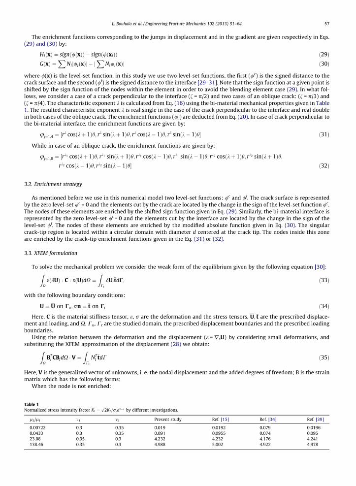
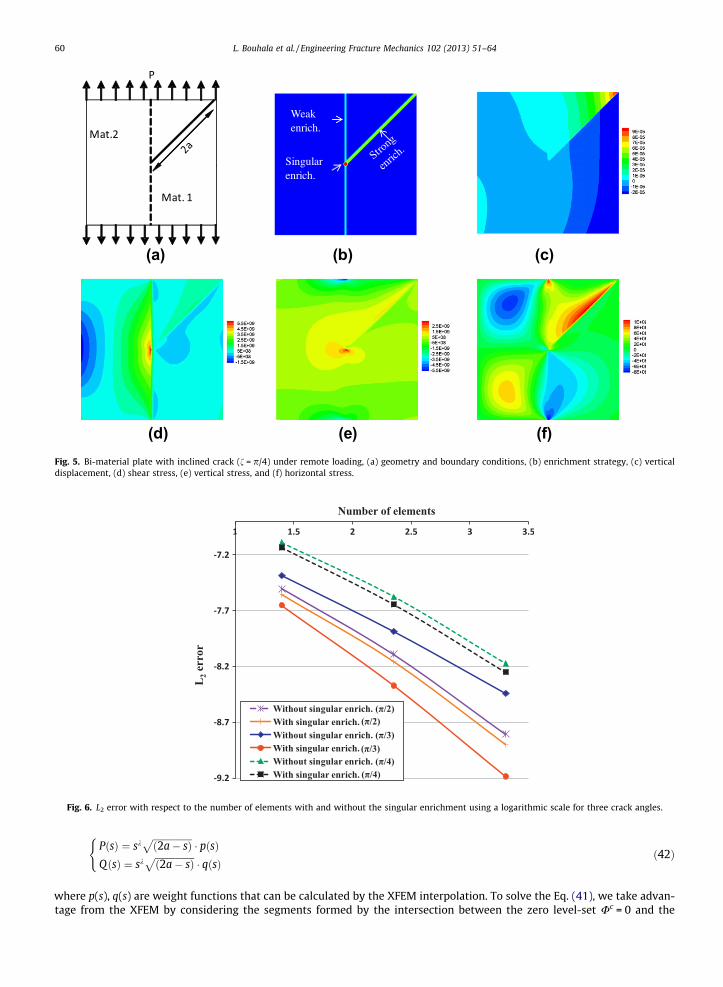
The convergence study is carried out for the case where the crack is perpendicular to the interface (f = p/2) and the twocases where the crack is oblique: (f = p/4) and (f = p/3). The case of interfacial crack corresponding to an imaginary charac-teristic exponent was already treated by means of the XFEM in [28]. To conduct the convergence study, a bi-material withthe following properties l1 = 206 GPa, m1 = 0.35, l2/l1 = 138.46, m2 = 0.3 (see Table 1) is subjected to a remote load P (seeFig. 4a). The dimensions of the studied domain are [8 mm] � [8 mm] and the crack-tip intersects the bi-material interfaceat its middle (4 mm from the external edge). The problem is first solved using a high mesh density (about 40,000 degreeof freedom) for both the perpendicular and the oblique cracks, where the solution serves as a reference for the convergencestudy. The displacement in the applied load direction and the stress components are given in Fig. 4 in case of a crack per-pendicular to the bi-material interface, and those corresponding to an oblique crack are given in Fig. 5. Figs. 6 and 7 showrespectively the plot of L2 and H1 error norms vs the total number of the elements used in the simulation for different crackangles, f = p/2, f = p/4 and f = p/3. For both the L2 error norm and H1 error norm, the singular enrichment improves the con-vergence. The error is smaller and the slope of the convergence is larger with the use of the singular enrichment compared tothe ones without the singular enrichment. Note that, the basis of the singular enrichment functions are of number of fourwhen the crack is perpendicular to the bi-material interface (f = p/2) and eight in the case of the oblique crack (f = p/4,f = p/3). Fig. 8 shows the variation of the condition number vs the number of degrees of freedom with and without the sin-gular enrichment. To keep the condition number low and to avoid large ill-conditioned Jacobian matrix, the crack-tip en-riched area is taken circular with a radius equal to two times the crack-tip element size. Indeed, in case of a crack alonga bi-material interface, Sukumar et al. [28] showed that the XFEM solution becomes independent of the crack-tip enrichment

(f)
(b) (c)
(e)(d)
(a)
Fig. 4. Bi-material plate under remote loading where the Material-1 (cracked material) is stiffer than the material-2, (a) geometry and boundary conditions,(b) enrichment strategy, (c) vertical displacement, (d) shear stress, (e) vertical stress, and (f) horizontal stress.
L. Bouhala et al. / Engineering Fracture Mechanics 102 (2013) 51–64 59
area once its radius is two-times the crack tip element size. Further, Laborde et al. [9] used XFEM with fixed enrichment areathat results in better convergence over the standard XFEM where only the nearest nodes to the crack-tip are enriched. Theprocedure of enrichment and the obtained fields are plotted in Figs. 4 and 5.
4. Validation by means of the stress intensity factor
The validation is done by considering a bi-material with a crack lying in one of the two materials (Material-1) and ter-minating on the interface (see Fig. 4a). The stress intensity factors (SIF) are calculated for different combinations of themechanical properties mismatch using the body force method (BFM). A crack perpendicular to the bi-material interface isconsidered here since methods for the calculation of KIand KII exist in the literature. The determination of the SIF KI andKII in the case of cracks terminating at the interface of a bi-material is one of the most difficult post-processing tasks. Notethat, in this case, not all the classical techniques are suitable to compute the SIF due to the complexity of the problem. Usu-ally, the interpolation, the isoparametric finite element method and the BFMs are the most used techniques to compute theSIF for this kind of problems, see [15,32–39].
In this work, the XFEM solution is combined with the BFM, where the stress around the crack is determined numericallyfrom the solution and not prescribed contrarily to Ref. [15] from where the following equations are derived. In the BFM thestresses are replaced by a tension and a shear type force doublets at the crack surface. The specified traction condition on thecrack surface must satisfy the following equation:
R 2a0 RQ
x ðX2; sÞ � RQx ðX1; sÞ
h iQðsÞds ¼
R X2X1
sðsÞdsR 2a0 RP
yðX2; sÞ � RPyðX1; sÞ
h iPðsÞds ¼
R X2X1
rnðsÞds
8><>: with : 0 6 X1 6 X2 6 2a ð41Þ
where 2a is the crack length, (X1,0) and (X2,0) are the bounds of the interval in which varies the point with local coordinates(s,0), i.e. small segments dividing the crack. Rm
i ðX2; sÞ � Rmi ðX1; sÞ
� �is the resultant forces acting at points (s,0), and s(s) and
rn(s) are the shear and the normal stress at points (s,0). The expression of the resultant forces is given as a function of theposition and the bi-material properties, the definition of Rm
i is expressed in [15,38]. While the density functions Q(s) and P(s)are given by:
Weak enrich.
Singular enrich.
(b) (c)
(d) (e) (f)
(a)
Fig. 5. Bi-material plate with inclined crack (f = p/4) under remote loading, (a) geometry and boundary conditions, (b) enrichment strategy, (c) verticaldisplacement, (d) shear stress, (e) vertical stress, and (f) horizontal stress.
Fig. 6. L2 error with respect to the number of elements with and without the singular enrichment using a logarithmic scale for three crack angles.
60 L. Bouhala et al. / Engineering Fracture Mechanics 102 (2013) 51–64
PðsÞ ¼ skffiffiffiffiffiffiffiffiffiffiffiffiffiffiffiffiffið2a� sÞ
p� pðsÞ
QðsÞ ¼ skffiffiffiffiffiffiffiffiffiffiffiffiffiffiffiffiffið2a� sÞ
p� qðsÞ
(ð42Þ
where p(s), q(s) are weight functions that can be calculated by the XFEM interpolation. To solve the Eq. (41), we take advan-tage from the XFEM by considering the segments formed by the intersection between the zero level-set Uc = 0 and the
Fig. 7. H1 error with respect to the number of elements with and without the singular enrichment using a logarithmic scale for three crack angles.
Fig. 8. The condition number evolution with respect to the degrees of freedom number for the perpendicular crack with and without singular enrichment.
L. Bouhala et al. / Engineering Fracture Mechanics 102 (2013) 51–64 61
element edges adding to that the segment formed between the crack tip element edge and the crack tip, see Fig. 9. Thevariable s takes the values of the Gauss points coordinates generated on these segments. The variables p1, p2, p3, . . . , pn
and q1, q2, q3, . . . , qn are the unknowns at the set of the intersection points d1, d2, d3, . . . , dn (Fig. 9). The integrands in theEq. (41) are calculated on each Gauss point so that, in the left side term appears the unknowns and in the right side term,the stresses are interpolated from the numerical solution. Thus, the following two linear equation systems are obtained:Kp
ij
h ifpjg ¼ Fp
i
� �, Kq
ij
h ifqjg ¼ Fq
i
� �. Once the system of equation is solved, the SIF can be directly obtained as:
KI ¼2ffiffiffiffiffiffi2ap
kð1� aÞð2kb� 1Þðj1 � 1Þðb2 � 1Þðj1 þ 1Þ2 sinðkpÞ
p1 ð43Þ
KII ¼�2
ffiffiffiffiffiffi2ap
kð1� aÞð2kbþ 1Þðb2 � 1Þðj1 þ 1Þ sinðkpÞ
q1 ð44Þ
Here a and b are the Dundurs bi-material parameters [35]. The simulations are carried out for different materials stiffnessratios in the case of plane strain assumptions, where li, mi are respectively the shear modulus and Poisson’s coefficient. Usingan average of 7000 degrees of freedom, the obtained stress intensity factors for different material pairs are summarized inTable 1. The results are in good agreement with the results found in [15,34,40].
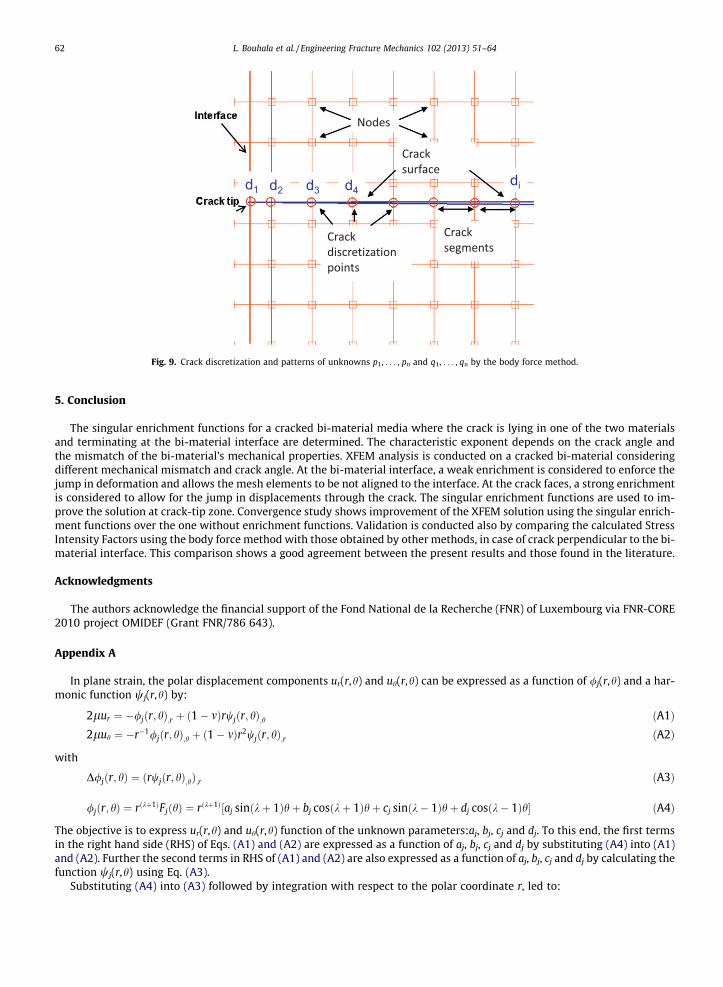
Fig. 9. Crack discretization and patterns of unknowns p1, . . . , pn and q1, . . . , qn by the body force method.
62 L. Bouhala et al. / Engineering Fracture Mechanics 102 (2013) 51–64
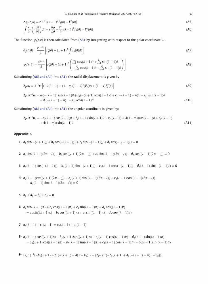
5. Conclusion
The singular enrichment functions for a cracked bi-material media where the crack is lying in one of the two materialsand terminating at the bi-material interface are determined. The characteristic exponent depends on the crack angle andthe mismatch of the bi-material’s mechanical properties. XFEM analysis is conducted on a cracked bi-material consideringdifferent mechanical mismatch and crack angle. At the bi-material interface, a weak enrichment is considered to enforce thejump in deformation and allows the mesh elements to be not aligned to the interface. At the crack faces, a strong enrichmentis considered to allow for the jump in displacements through the crack. The singular enrichment functions are used to im-prove the solution at crack-tip zone. Convergence study shows improvement of the XFEM solution using the singular enrich-ment functions over the one without enrichment functions. Validation is conducted also by comparing the calculated StressIntensity Factors using the body force method with those obtained by other methods, in case of crack perpendicular to the bi-material interface. This comparison shows a good agreement between the present results and those found in the literature.
Acknowledgments
The authors acknowledge the financial support of the Fond National de la Recherche (FNR) of Luxembourg via FNR-CORE2010 project OMIDEF (Grant FNR/786 643).
Appendix A
In plane strain, the polar displacement components ur(r,h) and uh(r,h) can be expressed as a function of /j(r,h) and a har-monic function wj(r,h) by:
2lur ¼ �/jðr; hÞ;r þ ð1� mÞrwjðr; hÞ;h ðA1Þ2luh ¼ �r�1/jðr; hÞ;h þ ð1� mÞr2wjðr; hÞ;r ðA2Þ
with
D/jðr; hÞ ¼ ðrwjðr; hÞ;hÞ;r ðA3Þ
/jðr; hÞ ¼ rðkþ1ÞFjðhÞ ¼ rðkþ1Þ½aj sinðkþ 1Þhþ bj cosðkþ 1Þhþ cj sinðk� 1Þhþ dj cosðk� 1Þh� ðA4Þ
The objective is to express ur(r,h) and uh(r,h) function of the unknown parameters:aj, bj, cj and dj. To this end, the first termsin the right hand side (RHS) of Eqs. (A1) and (A2) are expressed as a function of aj, bj, cj and dj by substituting (A4) into (A1)and (A2). Further the second terms in RHS of (A1) and (A2) are also expressed as a function of aj, bj, cj and dj by calculating thefunction wj(r,h) using Eq. (A3).
Substituting (A4) into (A3) followed by integration with respect to the polar coordinate r, led to:
L. Bouhala et al. / Engineering Fracture Mechanics 102 (2013) 51–64 63
D/jðr; hÞ ¼ rðk�1Þ½ðkþ 1Þ2FjðhÞ þ F 00j ðhÞ� ðA5ÞZ@
@rr@w@h
dr ¼ r
@w@h¼ rk
k½ðkþ 1Þ2FjðhÞ þ F 00j ðhÞ� ðA6Þ
The function wj(r,h) is then calculated from (A6), by integrating with respect to the polar coordinate h.
wjðr; hÞ ¼rðk�1Þ
kF 0jðhÞ þ ðkþ 1Þ2
ZFjðhÞdh
� �ðA7Þ
wjðr; hÞ ¼rðk�1Þ
kF 0jðhÞ þ ðkþ 1Þ2
�aj
kþ1 cosðkþ 1Þhþ bj
kþ1 sinðkþ 1Þh
� cj
k�1 cosðk� 1Þhþ dj
k�1 sinðk� 1Þh
0@
1A
24
35 ðA8Þ
Substituting (A6) and (A4) into (A1), the radial displacement is given by:
2lur ¼ k�1rk ð�kðkþ 1Þ þ ð1� mjÞð1þ kÞ2ÞFjðhÞ þ ð1� mÞF 00j ðhÞh i
ðA9Þ
2lkr�kur ¼ ajð�ðkþ 1ÞÞ sinðkþ 1Þhþ bjð�ðkþ 1ÞÞ cosðkþ 1Þhþ cjð�ðkþ 1Þ þ 4ð1� mjÞÞ sinðk� 1Þhþ djð�ðkþ 1Þ þ 4ð1� mjÞÞ cosðk� 1Þh ðA10Þ
Substituting (A8) and (A4) into (A1), the angular coordinate is given by:
2lkr�kuh ¼ �ajðkþ 1Þ cosðkþ 1Þhþ bjðkþ 1Þ sinðkþ 1Þh� cjððk� 1Þ þ 4ð1� mjÞÞcosðk� 1Þhþ djððk� 1Þþ 4ð1� mjÞÞ sinðk� 1Þh ðA11Þ
Appendix B
1- a1 sinð�ðkþ 1ÞfÞ þ b1 cosð�ðkþ 1ÞfÞ þ c1 sinð�ðk� 1ÞfÞ þ d1 cosð�ðk� 1ÞfÞ ¼ 0
2- a2 sinððkþ 1Þð2p� fÞÞ þ b2 cosððkþ 1Þð2p� fÞÞ þ c2 sinððk� 1Þð2p� fÞÞ þ d2 cosððk� 1Þð2p� fÞÞ ¼ 0
3- a1ðkþ 1Þ cosð�ðkþ 1ÞfÞ � b1ðkþ 1Þ sinð�ðkþ 1ÞfÞ þ c1ðk� 1Þ cosð�ðk� 1ÞfÞ � d1ðk� 1Þ sinð�ðk� 1ÞfÞ ¼ 0
4- a2ðkþ 1Þcosððkþ 1Þð2p� fÞÞ � b2ðkþ 1Þ sinððkþ 1Þð2p� fÞÞ þ c2ðk� 1Þcosððk� 1Þð2p� fÞÞ
� d2ðk� 1Þ sinððk� 1Þð2p� fÞÞ ¼ 05- b1 þ d1 ¼ b3 þ d3 ¼ 0
6- a2 sinððkþ 1ÞpÞ þ b2 cosððkþ 1ÞpÞ þ c2 sinððk� 1ÞpÞ þ d2 cosððk� 1ÞpÞ
¼ a3 sinððkþ 1ÞpÞ þ b3 cosððkþ 1ÞpÞ þ c3 sinððk� 1ÞpÞ þ d3 cosððk� 1ÞpÞ7- a1ðkþ 1Þ þ c1ðk� 1Þ ¼ a3ðkþ 1Þ þ c3ðk� 1Þ
8- a2ðkþ 1Þ cosððkþ 1ÞpÞ � b2ðkþ 1Þ sinððkþ 1ÞpÞ þ c2ðk� 1Þ cosððk� 1ÞpÞ � d2ðk� 1Þ sinððk� 1ÞpÞ
¼ a3ðkþ 1Þ cosððkþ 1ÞpÞ � b3ðkþ 1Þ sinððkþ 1ÞpÞ þ c3ðk� 1Þ cosððk� 1ÞpÞ � d3ðk� 1Þ sinððk� 1ÞpÞ9- ð2l1Þ�1ð�b1ðkþ 1Þ þ d1ð�ðkþ 1Þ þ 4ð1� t1ÞÞÞ ¼ ð2l3Þ
�1ð�b3ðkþ 1Þ þ d3ð�ðkþ 1Þ þ 4ð1� t3ÞÞÞ

64 L. Bouhala et al. / Engineering Fracture Mechanics 102 (2013) 51–64
10- ð2l2Þ�1 �a2ðkþ 1Þ sinððkþ 1ÞpÞ � b2ðkþ 1Þcosððkþ 1ÞpÞ þ c2ð�ðkþ 1Þ þ 4ð1� m2ÞÞ sinððk� 1ÞpÞ½
þ d2ð�ðkþ 1Þ þ 4ð1� m2ÞÞ cosððkþ 1ÞpÞ�¼ ð2l3Þ
�1 �a3ðkþ 1Þ sinððkþ 1ÞpÞ � b3ðkþ 1Þcosððkþ 1ÞpÞ þ c3ð�ðkþ 1Þ þ 4ð1� m3ÞÞ sinððk� 1ÞpÞ½þ d3ð�ðkþ 1Þ þ 4ð1� m3ÞÞ cosððk� 1ÞpÞ�
11- ð2l1Þ�1ða1ð�ðkþ 1ÞÞ þ c1ð�ðkþ 1Þ � 4ð1� m1ÞÞÞ ¼ ð2l3Þ
�1ða3ð�ðkþ 1ÞÞ þ c3ð�ðkþ 1Þ � 4ð1� m3ÞÞÞ
12- ð2l2Þ�1 �a2ðkþ 1Þ cosððkþ 1ÞpÞ þ b2ðkþ 1Þ sinððkþ 1ÞpÞ � c2ððk� 1Þ þ 4ð1� m2ÞÞ cosððk� 1ÞpÞ þ d2ððk� 1Þ½
þ4ð1� m2ÞÞ sinððk� 1ÞpÞ� ¼ ð2l3Þ�1 �a3ðkþ 1Þcosððkþ 1ÞpÞ þ b3ðkþ 1Þ sinððkþ 1ÞpÞ � c3ððk� 1Þ½
þ4ð1� m3ÞÞ cosððk� 1ÞpÞ þ d3ððk� 1Þ þ 4ð1� m3ÞÞ sinððk� 1ÞpÞ�
References
[1] Fix GJ, Gulati S, Wakoff GI. On the use of singular functions with finite element approximations. J Comput Phys 1973;13:209–28.[2] Strang G, Fix GJ. An analysis of finite element method. Cliffs, NJ: Prentice-Hall Englewood; 1973.[3] Melenk JM, Babuska I. The partition of unity finite element method: basic theory and applications. Comput Meth Appl Mech Engng 1996;39:289–314.[4] Bordas S, Moran B. Enriched finite elements and level sets for damage tolerance assessment of complex structures. Engng Fract Mech
2006;73:1176–201.[5] Sukumar N, Chopp DL, Moes N, Belytchko T. Modeling holes and inclusions by level sets in the extended finite element method. Comput Meth Appl
Mech Engng 2001;190:183–6200.[6] Belytchko T, Black N, Moes N, Sukumar N, Usui S. Structured extended finite element methods of solids defined by implicit surfaces. Int J Numer Meth
Engng 2003;56:609–35.[7] Belytschko T, Moes N, Usui S, Parimi C. Arbitrary discontinuities in finite elements. Int J Num Meth Engng 2001;51:943–60.[8] Moes N, Cloirec M, Cartraud P, Remacle JF. A computational approach to handle complex microstructure geometries. Comput Meth App Mech Engng
2003;192:3163–77.[9] Laborde P, Pommier J, Renard Y, Salaun M. High-order extended finite element method for cracked domains. Int J Numer Meth Engng 2005;64:354–81.
[10] Béchet E, Minnebo H, Moës N, Burgardt B. Improved implementation and robustness study of the XFEM method for stress analysis around cracks. Int JNumer Meth Engng 2005;64:1033–56.
[11] Chahine E, Laborde P, Renard Y. Crack tip enrichment in the XFEM using a cutoff function. Int J Numer Meth Engng 2008;75:629–46.[12] Nicaise S, Renard Y, Chahine E. Optimal convergence analysis for the extended finite element method. Int J Numer Meth Engng 2011;86:528–48.[13] Nahlik L, Zdenek K, Klusak J. Crack initiation criteria for singular stress concentrations, part III: an application to a crack touching a bi-material. Engng
Mech 2008;15:99–114.[14] Lin YY, Sung JC. Singularities of an inclined crack terminating at an anisotropic bi-material interface. Int J Solids Struct 1997;34:3727–54.[15] CHEN Dai-Heng. A crack normal to and terminating at a bi-material interface. Engng Fract Mech 1994;49:517–32.[16] Li J, Zhang XB, Recho N. Stress singularities near the tip of a 2D notch formed from several elastic anisotropic materials. Int J Fract 2001;107:379–95.[17] Menk A, Bordas SPA. Numericaly determined enrichment functions for the XFEM and application to bi-material anisotropic fracture and polycrystals. J
Numer Meth Engng 2010;83:805–28.[18] Menk A, Bordas SPA. Crack growth calculations in solder joints based on micro structural phenomena with XFEM. Comput Mat Sci 2011;50:1145–56.[19] Mandell JF, Huang DD, McGarry FJ. Crack propagation modes in injection molded fiber reinforced thermoplastics. Research report R80-3, Department
of Materials Science and Engineering. MIT, USA; 1980.[20] Nahlik L, Knesl Z, Klusak J. Crack initiation criteria for singular stress concentrations, part III: an application to a crack touching a bi-material interface.
Engng Mech 2008;15:99–114.[21] Lin YY, Sung JC. Singularities of an inclined crack terminating at an anisotropic biomaterial interface. Int J Solids Struct 1997;34:3727–54.[22] Comninou Maria. An overview of interface cracks. Engng Fract Mech 1990;37(1):197–208.[23] Williams ML. On the stress distribution at the base of a stationary crack. J Appl Mech 1957;24:109–14.[24] Williams ML. stress singularities resulting from various boundary conditions in angular corners of plates in extension. J Appl Mech 1952;19:526–8.[25] Bouhala L, Belouettar S, Makradi A, Remond Y. Study of interface influence on crack growth: application to solid oxide fuel cell like materials design.
Mater Des 2010;31:1041–133.[26] Bouhala L, Makradi A, Belouettar S. Thermal and thermo-mechanical influence on crack propagation using an extended mesh free method. Engng Fract
Mech 2012;88:35–48.[27] Moës N, Dolbow J, Belytschko T. A finite element method for crack growth without remeshing. Int J Numer Meth Engng 1999;46:131–50.[28] Sukumar N, Huang ZY, Pévost JH, Suo Z. Partition of unity enrichment for bi-material interface cracks. Int J Numer Meth Engng 2004;59:1075–102.[29] Fries TP. The extended/generalized finite element method: an overview of the method and its applications. Int J Numer 2010:253–304.[30] Makradi A, Bouhala L, Belouettar S. Crack growth in fibre-reinforced composites: experimental analysis, modelling and simulation. Revue technique
luxembourgeoise 2012;2:38–45.[31] Chessa J, Wang H, Belytschko T. On the construction of blending elements for local partition of unity enriched finite elements. Int J Numer Meth Engng
2003;57:1015–38.[32] Tzuchiang W. a crack perpendicular to and terminating at a bi-material interface. Acta Mech Sin 1998;14:27–36.[33] Wang TC. Stress state in front of a crack perpendicular to bi-material interface. Engng Fract Mech 1998;59(4):471–85.[34] Cook TS, Erdogan F. Stress in bounded material with a crack perpendicular to the interface. Int J Engng Sci 1972;10:677–97.[35] Dundurs J. Effect of elastic constants on stress in a composite under plane deformation. J Comp Mater 1967;1:301–22.[36] Nisitani H, Chen DH. Body force method and its applications to numerical and theoretical problems in fracture and damage. Comput Mech
1997;19(6):470–80.[37] Chen DH, Nisitani H. Body force method. Int J Fract 1997;86(1–2):161–89.[38] Frasier JT, Rongved L. Force in the plane of two joined semi-infinite plates. J Appl Mech 1957;24:582–4.[39] Lim Won-kyun, Lee Chang-so. Evaluation of stress intensity factors for a crack normal to bi-material interface using isoparametric finite elements.
Engng Fract Mech 1995;52(1):65–70.[40] Lin KY, Mar JW. Finite element analysis of stress intensity factors for cracks at a bi-material interface. Int J Fract 1976;12:521–31.