Embed Size (px)
Citation preview
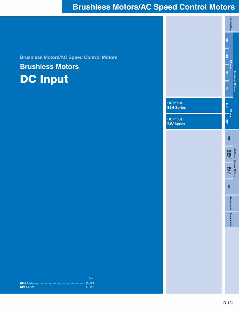
D-131
Brushless Motors/AC Speed Control MotorsIn
trod
uctio
n
Bru
shless M
oto
rsA
C S
peed
Co
ntro
l Mo
tors
Accesso
riesIn
stallation
AC
Inp
ut
DC
Inp
ut
BH
FFE1
00/
FE200
ES01/
ES02
US
BX
BLF
BLE
BLU
BLH
BLV
Page
BLH Series ····························································· D-132BLV Series ······························································ D-148
DC InputBLH Series
DC InputBLV Series
Brushless Motors/AC Speed Control Motors
Brushless Motors
DC Input
PageORIENTAL MOTOR GENERAL CATALOG 2012/2013
D-132 Features D-132 / System Configuration D-133 / Product Line D-134 / Specifications D-134 / Characteristics D-135 Dimensions D-138 / Connection and Operation D-144 / Motor and Driver Combinations D-147
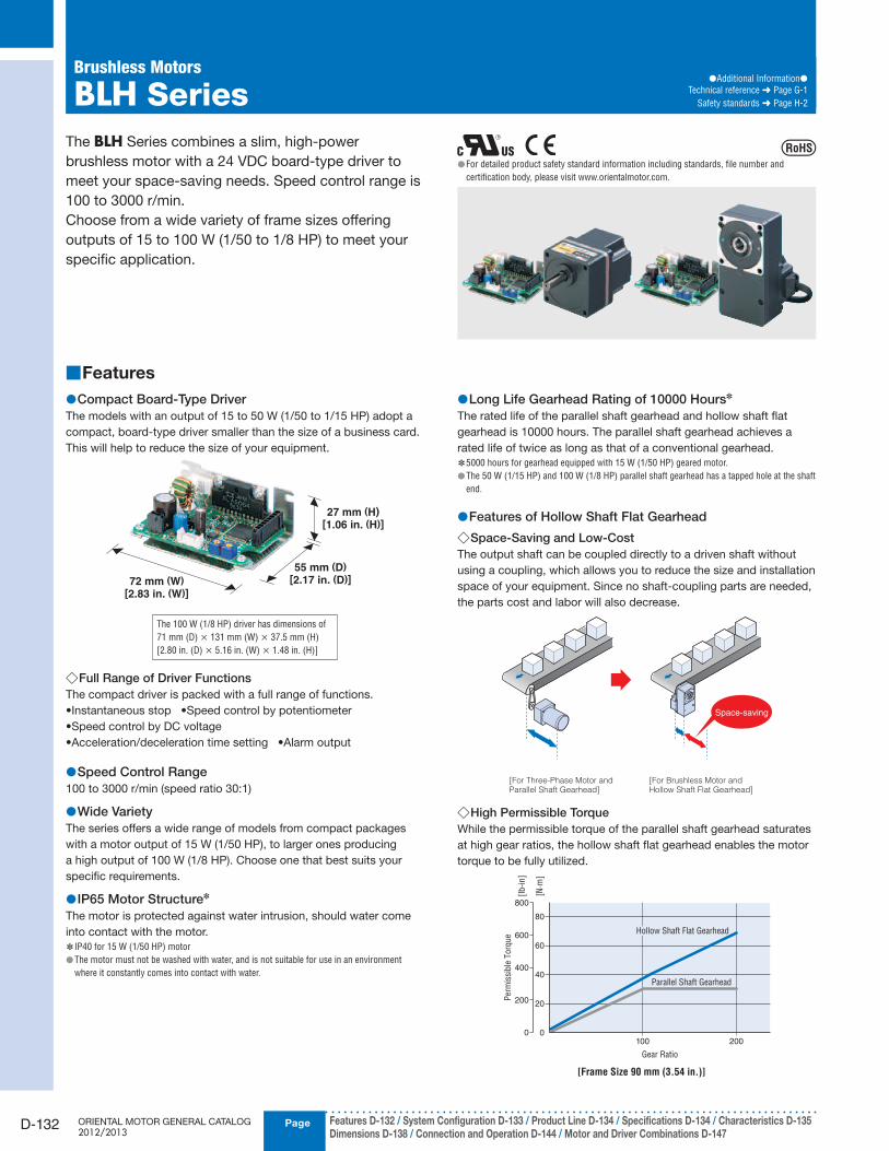
The BLH Series combines a slim, high-power
brushless motor with a 24 VDC board-type driver to
meet your space-saving needs. Speed control range is
100 to 3000 r/min.
Choose from a wide variety of frame sizes offering
outputs of 15 to 100 W (1/50 to 1/8 HP) to meet your
specific application.
Features ■
Compact Board-Type Driver ●The models with an output of 15 to 50 W (1/50 to 1/15 HP) adopt a
compact, board-type driver smaller than the size of a business card.
This will help to reduce the size of your equipment.
72 mm (W)[2.83 in. (W)]
55 mm (D)[2.17 in. (D)]
27 mm (H)[1.06 in. (H)]
The 100 W (1/8 HP) driver has dimensions of
71 mm (D) × 131 mm (W) × 37.5 mm (H)
[2.80 in. (D) × 5.16 in. (W) × 1.48 in. (H)]
Full Range of Driver Functions ◇The compact driver is packed with a full range of functions.
•Instantaneous stop •Speed control by potentiometer
•Speed control by DC voltage
•Acceleration/deceleration time setting •Alarm output
Speed Control Range ●100 to 3000 r/min (speed ratio 30:1)
Wide Variety ●The series offers a wide range of models from compact packages
with a motor output of 15 W (1/50 HP), to larger ones producing
a high output of 100 W (1/8 HP). Choose one that best suits your
specific requirements.
IP65 Motor Structure ● ✽
The motor is protected against water intrusion, should water come
into contact with the motor.
IP40 for 15 W (1/50 HP) motor ✽
The motor must not be washed with water, and is not suitable for use in an environment ●where it constantly comes into contact with water.
Long Life Gearhead Rating of 10000 Hours ● ✽
The rated life of the parallel shaft gearhead and hollow shaft flat
gearhead is 10000 hours. The parallel shaft gearhead achieves a
rated life of twice as long as that of a conventional gearhead.
5000 hours for gearhead equipped with 15 W (1/50 HP) geared motor. ✽
The 50 W (1/15 HP) and 100 W (1/8 HP) parallel shaft gearhead has a tapped hole at the shaft ●end.
Features of Hollow Shaft Flat Gearhead ●Space-Saving and Low-Cost ◇
The output shaft can be coupled directly to a driven shaft without
using a coupling, which allows you to reduce the size and installation
space of your equipment. Since no shaft-coupling parts are needed,
the parts cost and labor will also decrease.
Space-saving
[For Three-Phase Motor and Parallel Shaft Gearhead]
[For Brushless Motor and Hollow Shaft Flat Gearhead]
High Permissible Torque ◇While the permissible torque of the parallel shaft gearhead saturates
at high gear ratios, the hollow shaft flat gearhead enables the motor
torque to be fully utilized.
100 200
80
60
40
20
0
Gear Ratio
Per
mis
sible
Torq
ue
Parallel Shaft Gearhead
Hollow Shaft Flat Gearhead
800
600
400
200
0
[N·m
]
[lb-i
n]
[Frame Size 90 mm (3.54 in.)]
For detailed product safety standard information including standards, file number and ●certification body, please visit www.orientalmotor.com.
Brushless Motors
BLH Series●Additional Information●
Technical reference ➜ Page G-1
Safety standards ➜ Page H-2
CAD DataManuals
www.orientalmotor.com Technical Support
TEL: (800) 468-3982E-mail: [email protected]
D-133
Brushless Motors/AC Speed Control MotorsIn
trod
uctio
n
Bru
shless M
oto
rsA
C S
peed
Co
ntro
l Mo
tors
Accesso
riesIn
stallation
AC
Inp
ut
DC
Inp
ut
BH
FFE1
00/
FE200
ES01/
ES02
US
BX
BLF
BLE
BLU
BLH
BLV
System Configuration ■
Flexible Couplings(➜ Page C-269)
Connection Cables, Flexible Connection Cables(➜ Page D-229)
Accessories (Sold separately)
BLH Series
Combination Type(Motor/Gearhead)
Driver
Power Supply Cable(Included)
I/O Signal Cable (Included)
Accessories (Sold separately)
ProgrammableController✽
24 VDC Power Supply✽
Mounting Brackets(➜ Page C-264)
Motor Speed Indicator●Not a standard certified product
(➜ Page D-234)
External Speed Potentiometer(➜ Page D-230)
●Example of System Configuration
BLH Series
Combination Type - Parallel Shaft
BLH450KC-30
External Speed
PotentiometerFlexible Coupling
PAVR-20KZ SOL4M6 MCL5515F10
Mounting Bracket
CC02BLH
Connection Cable
[1.5 m (4.9 ft.)]
SDM496
Motor Speed
Indicator
Sold Separately
The system confi guration shown above is an example. Other combinations are available. ●Not supplied ✽
PageORIENTAL MOTOR GENERAL CATALOG 2012/2013
D-134 Features D-132 / System Configuration D-133 / Product Line D-134 / Specifications D-134 / Characteristics D-135 Dimensions D-138 / Connection and Operation D-144 / Motor and Driver Combinations D-147
Brushless Motors/BLH Series
Product Number Code ■
BLH 2 30 K C - 5 FR① ② ③ ④ ⑤ ⑥ ⑦
Product Line ■
Combination Type The combination type comes with the motor and its dedicated gearhead pre-assembled which simplifies installation in
equipment. Motors and gearheads are also available separately to facilitate changes or repairs.
Geared Type The geared type has an integrated motor and gearhead. The combination of motor and gearhead cannot be changed.
Geared Type/Combination Type – Parallel Shaft Gearhead ●Type Output Power Model Gear Ratio
Geared Type15 W
(1/50 HP)BLH015K-□ 5, 10, 15, 20, 30,
50, 100
Combination Type
30 W
(1/25 HP)BLH230KC-□ 5, 10, 15, 20, 30,
50, 100, 20050 W
(1/15 HP)BLH450KC-□ 5, 10, 15, 20, 30,
50, 100, 200100 W
(1/8 HP)BLH5100KC-□ 5, 10, 15, 20, 30,
50, 100, 200
Motor, Driver, Gearhead, I/O Signal Cable, Power Supply
Cable, Mounting Screws✽1, Parallel Key✽2, Operating Manual
1 Only for combination type ✽
2 Only for the products with a key slot on the output shaft ✽
The following items are included in each product.
Combination Type – Hollow Shaft Flat Gearhead ●Output Power Model Gear Ratio
30 W
(1/25 HP)BLH230KC-□FR 5, 10, 15, 20, 30,
50, 100, 20050 W
(1/15 HP)BLH450KC-□FR 5, 10, 15, 20, 30,
50, 100, 200100 W
(1/8 HP)BLH5100KC-□FR 5, 10, 15, 20, 30,
50, 100, 200
Motor, Driver, Gearhead, I/O Signal Cable, Power Supply Cable, Mounting
Screws, Parallel Key, Safety Cover (with screws), Operating Manual
The following items are included in each product.
Round Shaft Type ●Output Power Model
15 W (1/50 HP) BLH015K-A30 W (1/25 HP) BLH230KC-A50 W (1/15 HP) BLH450KC-A100 W (1/8 HP) BLH5100KC-A
① Series BLH: BLH Series
②Motor Frame Size 0: 42 mm (1.65 in.) 2: 60 mm (2.36 in.) 4: 80 mm (3.15 in.)
5: 90 mm (3.54 in.)
③ Output Power (W) (Example) 30: 30 W (1/25 HP)
④ Power Supply Voltage K: 24 VDC
⑤ C: Cable Type
⑥Gear Ratio/Shaft Type Number: Gear ratio for combination types: 8 types from 5 to 200
Gear ratio for geared types: 7 types from 5 to 100A: Round Shaft Type
⑦Blank: Combination Type – Parallel Shaft Gearhead
FR: Combination Type – Hollow Shaft Flat Gearhead
Motor, Driver, I/O Signal Cable, Power Supply Cable,
Operating Manual
The following items are included in each product.
Specifications ■
15 W (1/50 HP), 30 W (1/25 HP), 50 W (1/15 HP), 100 W (1/8 HP) ●
Model
Geared Type/Combination Type – Parallel Shaft Gearhead BLH015K-□ BLH230KC-□ BLH450KC-□ BLH5100KC-□Combination Type – Hollow Shaft Flat Gearhead − BLH230KC-□FR BLH450KC-□FR BLH5100KC-□FRRound Shaft Type BLH015K-A BLH230KC-A BLH450KC-A BLH5100KC-A
Rated Output Power (Continuous) W (HP) 15 (1/50) 30 (1/25) 50 (1/15) 100 (1/8)
Power
Source
Rated Voltage 24 VDC
Permissible Voltage Range ±10%
Rated Input Current A 1.0 2.1 3.1 6.0
Maximum Input Current A 2.4 3.7 5.4 9.8
Rated Torque N·m (oz-in) 0.05 (7.1) 0.12 (17) 0.2 (28) 0.4 (56)
Starting Torque✽ N·m (oz-in) 0.075 (10.6) 0.15 (21) 0.24 (34) 0.5 (71)
Rated Speed r/min 3000 2500
Speed Control Range r/min 100∼3000
Round Shaft Type
Permissible Load Inertia J×10-4kg·m2 (oz-in2) 0.5 (2.7) 1.8 (9.8) 3.3 (18.1) 5.6 (31)
Rotor Inertia J ×10-4kg·m2 (oz-in2) 0.032 (0.175) 0.087 (0.48) 0.23 (1.26) 0.61 (3.3)
Speed
Regulation
Load ±0.5% max. (0∼Rated torque, at rated speed, at rated voltage, at normal ambient temperature)
Voltage ±0.5% max. (Rated voltage ±10%, at rated speed, with no load, at normal ambient temperature)
Temperature ±0.5% max. [0∼+50˚C (+32∼+122˚F), at rated speed, with no load, at rated voltage]
The time during which the starting torque is effective is no more than 5 seconds and at 2000 r/min or below. ✽
The values for each specification apply to the motor only. ●
Enter the gear ratio in the box ( ● □) within the model name.
CAD DataManuals
www.orientalmotor.com Technical Support
TEL: (800) 468-3982E-mail: [email protected]
D-135
Brushless Motors/AC Speed Control MotorsIn
trod
uctio
n
Bru
shless M
oto
rsA
C S
peed
Co
ntro
l Mo
tors
Accesso
riesIn
stallation
AC
Inp
ut
DC
Inp
ut
BH
FFE1
00/
FE200
ES01/
ES02
US
BX
BLF
BLE
BLU
BLH
BLV
Common Specifications ■
Item Specifications
Speed Setting Method
Select one of the following methods:· Set using the internal speed potentiometer· Set using an accessory external speed potentiometer: PAVR-20KZ (20 kΩ, 1/4 W) (Sold separately)· Set using external DC voltage: 0∼5 VDC, 1 mA or more (Input impedance 47 kΩ)
Acceleration/Deceleration Time
0.5∼10 sec.
BLH015: at 3000 r/min with no load
BLH230, BLH450, BLH5100: at 2500 r/min with no load
(The actual speed may change by load condition.)
A common value is set using the acceleration/deceleration time potentiometer.
Multi-Speed Setting Method
Switching between 2 speeds
One speed is set by the internal speed potentiometer (1 pc), while another speed is set by an external speed potentiometer
(accessory PAVR-20KZ) or by external DC voltage (0∼5 VDC).
Input SignalsC-MOS negative logic input Operated by internal power supply
Common to Start/Stop input, Run/Brake input, Direction of rotation input, Speed control method input and Alarm reset input
Output SignalsOpen-collector output Operated by external power supply Use condition 26.4 VDC max., 10 mA max.
Common to Alarm output and Speed output
Protective Functions✽
When the following are activated, the motor will coast to a stop and the Alarm output will be OFF.
The alarm LED on the driver will blink for the corresponding number of times shown in ( ).· Overload protection (2): Activated when the motor load exceeds rated torque for a minimum of 5 seconds.· Motor sensor error (3): Activated when the sensor wire inside the motor cable is disconnected during motor operation.· Overvoltage protection (4): Activated when the voltage applied to the driver exceeds 24 VDC by a minimum of approximately 15%, a gravitational
operation is performed or a load exceeding the permissible load inertia is driven.· Undervoltage protection (5): Activated when the voltage applied to the driver falls below 24 VDC by a minimum of approximately 25%.· Overspeed protection (6): Activated when the motor speed exceeds 3500 r/min.
Maximum Cable Extension Distance Motor/Driver Distance: 2 m (6.6 ft.) (when an accessory connection cable is used)
Time Rating Continuous
With the ✽ BLH Series, the motor speed cannot be controlled in a gravitational operation or other application where the motor shaft is turned by the load. When a load exceeding the permissible
load inertia is driven or a gravitational operation is performed, the overvoltage protective function will be activated and the motor will coast to a stop.
BLH015K-□/BLH015K-A
1000100 2000 3000
Continuous Duty Region
Limited Duty Region
Speed [r /min]
0
0.05
0.075
Torq
ue
0.1
Rated Torque
Starting Torque
[N
·m]
14
12
10
8
6
4
2
0
[oz-
in]
BLH230KC-□/BLH230KC-□FR/BLH230KC-A
1000100 2000 3000
Continuous Duty Region
Limited Duty Region
Speed [r /min]
0
0.1
0.2
Rated Torque
✽50% of Rated Torque
0.15
0.12
Starting Torque
Torq
ue
[N
·m]
25
20
15
10
5
0
[oz-
in]
Value for 24 VDC with no connection cable ✽
BLH450KC-□/BLH450KC-□FR/BLH450KC-A
1000100 2000 3000
Continuous Duty Region
Limited Duty Region
Speed [r /min]
0.1
0.2
0.3 Rated Torque
0
✽50% of Rated Torque
0.24
Starting Torque
Torq
ue
[N
·m]
40
30
20
10
0
[oz-
in]
Value for 24 VDC with no connection cable ✽
●For geared types and combination types, the values are for the motor only.
Enter the gear ratio in the box ( ● □) within the model name.
BLH5100KC-□/BLH5100KC-□FR/BLH5100KC-A
1000100 2000 3000
Continuous Duty Region
Limited Duty Region
Speed [r /min]
0.2
0.4
0.5
0.6 Rated Torque
0
✽50% of Rated Torque
Starting Torque
Torq
ue
[N
·m]
80
60
40
20
0
[oz-
in]
Value for 24 VDC with no connection cable ✽
Speed – Torque Characteristics ■
Continuous Duty Region: Continuous operation is possible in this region.
Limited Duty Region: This region is used primarily when accelerating. When a load that exceeds the rated torque is applied continuously for
approximately five seconds, overload protection is activated and the motor coasts to a stop.
PageORIENTAL MOTOR GENERAL CATALOG 2012/2013
D-136 Features D-132 / System Configuration D-133 / Product Line D-134 / Specifications D-134 / Characteristics D-135 Dimensions D-138 / Connection and Operation D-144 / Motor and Driver Combinations D-147
Brushless Motors/BLH Series
General Specifications ■
Item Motor Driver
Insulation Resistance
100 MΩ or more when 500 VDC megger is applied between the
windings and the case after continuous operation under normal
ambient temperature and humidity.
100 MΩ or more when 500 VDC megger is applied between the
power supply terminal and heat sink after continuous operation
under normal ambient temperature and humidity.
Dielectric Strength
Sufficient to withstand 0.5 kVAC at 50 Hz applied between the
windings and the case for 1 minute after continuous operation under
normal ambient temperature and humidity.
Sufficient to withstand 0.5 kVAC at 50 Hz applied between the power
supply terminal and heat sink for 1 minute after continuous operation
under normal ambient temperature and humidity.
Temperature Rise
50˚C (90˚F) or less in the windings, and 40˚C (72˚F) or less in the
case✽1, as measured by the thermocouple method after continuous
operation under normal ambient temperature and humidity.
50˚C (90˚F) or less in the heat sink, as measured by the thermocouple
method after continuous operation under normal ambient
temperature and humidity.
Operating
Environment
Ambient Temperature 0∼+50˚C (+32∼+122˚F) (non-freezing)
Ambient Humidity 85% or less (non-condensing)
Altitude Up to 1000 m (3300 ft.) above sea level
Atmosphere No corrosive gases or dust. Cannot be used in a radioactive area, magnetic field, vacuum or other special environment
Vibration
Not subject to continuous vibration or excessive impact
In conformance with JIS C 60068-2-6, "Sine-wave vibration test method"
Frequency range: 10∼55 Hz Pulsating amplitude: 0.15 mm (0.006 in.)
Sweep direction: 3 directions (X, Y, Z) Number of sweeps: 20 times
Storage Condition✽2
Ambient Temperature −25∼+70˚C (−13∼+158˚F) (non-freezing)
Ambient Humidity 85% or less (non-condensing)
Altitude Up to 3000 m (10000 ft.) above sea level
Thermal Class UL/CSA standards: 105 (A), EN standards: 120 (E) −
Degree of Protection
15 W (1/50 HP) IP40
IP0030 W (1/25 HP),
50 W (1/15 HP),
100 W (1/8 HP)
IP65 (Excluding the mounting surface of the round shaft type and
connectors)
1 ✽ For round shaft types, please attach to the heat radiation plate (material: aluminum) of the following sizes to maintain a maximum motor case temperature of 90˚C (194˚F).
(Except for BLH015K-A)
BLH230KC-A: 115×115 mm (4.53×4.53 in.), 5 mm (0.20 in.) thick
BLH450KC-A: 135×135 mm (5.31×5.31 in.), 5 mm (0.20 in.) thick
BLH5100KC-A: 200×200 mm (7.87×7.87 in.), 5 mm (0.20 in.) thick
2 ✽ The storage condition applies to a short period such as a period during transportation.
Note ●Do not measure insulation resistance or perform the dielectric strength test while the motor and driver are connected.
Gearmotor – Torque Table of Geared Type/Combination Type ■
Geared Type/Combination Type – Parallel Shaft Gearhead ● Unit = N·m (lb-in)
Model
Gear Ratio 5 10 15 20 30 50 100 200
Motor Speed100∼2500 r/min 20∼500 10∼250 6.7∼167 5∼125 3.3∼83 2∼50 1∼25 0.5∼12.5
3000 r/min 600 300 200 150 100 60 30 15
BLH015K-□ 100∼3000 r/min 0.23 (2.0) 0.45 (3.9) 0.68 (6.0) 0.86 (7.6) 1.3 (11.5) 2 (17.7) 2 (17.7) −
BLH230KC-□100∼2500 r/min 0.54 (4.7) 1.1 (9.7) 1.6 (14.1) 2.2 (19.4) 3.1 (27) 5.2 (46) 6 (53) 6 (53)
3000 r/min 0.27 (2.3) 0.54 (4.7) 0.81 (7.1) 1.1 (9.7) 1.5 (13.2) 2.6 (23) 5.2 (46) 6 (53)
BLH450KC-□100∼2500 r/min 0.90 (7.9) 1.8 (15.9) 2.7 (23) 3.6 (31) 5.2 (46) 8.6 (76) 16 (141) 16 (141)
3000 r/min 0.45 (3.9) 0.90 (7.9) 1.4 (12.3) 1.8 (15.9) 2.6 (23) 4.3 (38) 8.6 (76) 16 (141)
BLH5100KC-□100∼2500 r/min 1.8 (15.9) 3.6 (31) 5.4 (47) 7.2 (63) 10.3 (91) 17.2 (152) 30 (260) 30 (260)
3000 r/min 0.90 (7.9) 1.8 (15.9) 2.7 (23) 3.6 (31) 5.2 (46) 8.6 (76) 17.2 (152) 30 (260)
A colored background ( ● ) indicates gear shaft rotation in the same direction as the motor shaft, while the others rotate in the opposite direction.
Combination Type – Hollow Shaft Flat Gearhead ● Unit = N·m (lb-in)
Model
Gear Ratio 5 10 15 20 30 50 100 200
Motor Speed100∼2500 r/min 20∼500 10∼250 6.7∼167 5∼125 3.3∼83 2∼50 1∼25 0.5∼12.5
3000 r/min 600 300 200 150 100 60 30 15
BLH230KC-□FR100∼2500 r/min 0.48 (4.2) 1.0 (8.8) 1.5 (13.2) 2.0 (17.7) 3.1 (27) 5.1 (45) 10.2 (90) 17 (150)
3000 r/min 0.24 (2.1) 0.51 (4.5) 0.77 (6.8) 1.0 (8.8) 1.5 (13.2) 2.6 (23) 5.1 (45) 10.2 (90)
BLH450KC-□FR100∼2500 r/min 0.85 (7.5) 1.7 (15) 2.6 (23) 3.4 (30) 5.1 (45) 8.5 (75) 17 (150) 34 (300)
3000 r/min 0.43 (3.8) 0.85 (7.5) 1.3 (11.5) 1.7 (15) 2.6 (23) 4.3 (38) 8.5 (75) 17 (150)
BLH5100KC-□FR100∼2500 r/min 1.7 (15) 3.4 (30) 5.1 (45) 6.8 (60) 10.2 (90) 17 (150) 34 (300) 68 (600)
3000 r/min 0.85 (7.5) 1.7 (15) 2.6 (23) 3.4 (30) 5.1 (45) 8.5 (75) 17 (150) 34 (300)
The flat gearhead rotates in the opposite direction to the motor when viewed from the front of the gearhead. It rotates in the same direction as the motor when viewed from the rear (motor mounting ●surface) of the gearhead. Rotation direction of the hollow shaft flat gearhead ➜ Page D-243
Enter the gear ratio in the box ( ● □) within the model name.
CAD DataManuals
www.orientalmotor.com Technical Support
TEL: (800) 468-3982E-mail: [email protected]
D-137
Brushless Motors/AC Speed Control MotorsIn
trod
uctio
n
Bru
shless M
oto
rsA
C S
peed
Co
ntro
l Mo
tors
Accesso
riesIn
stallation
AC
Inp
ut
DC
Inp
ut
BH
FFE1
00/
FE200
ES01/
ES02
US
BX
BLF
BLE
BLU
BLH
BLV
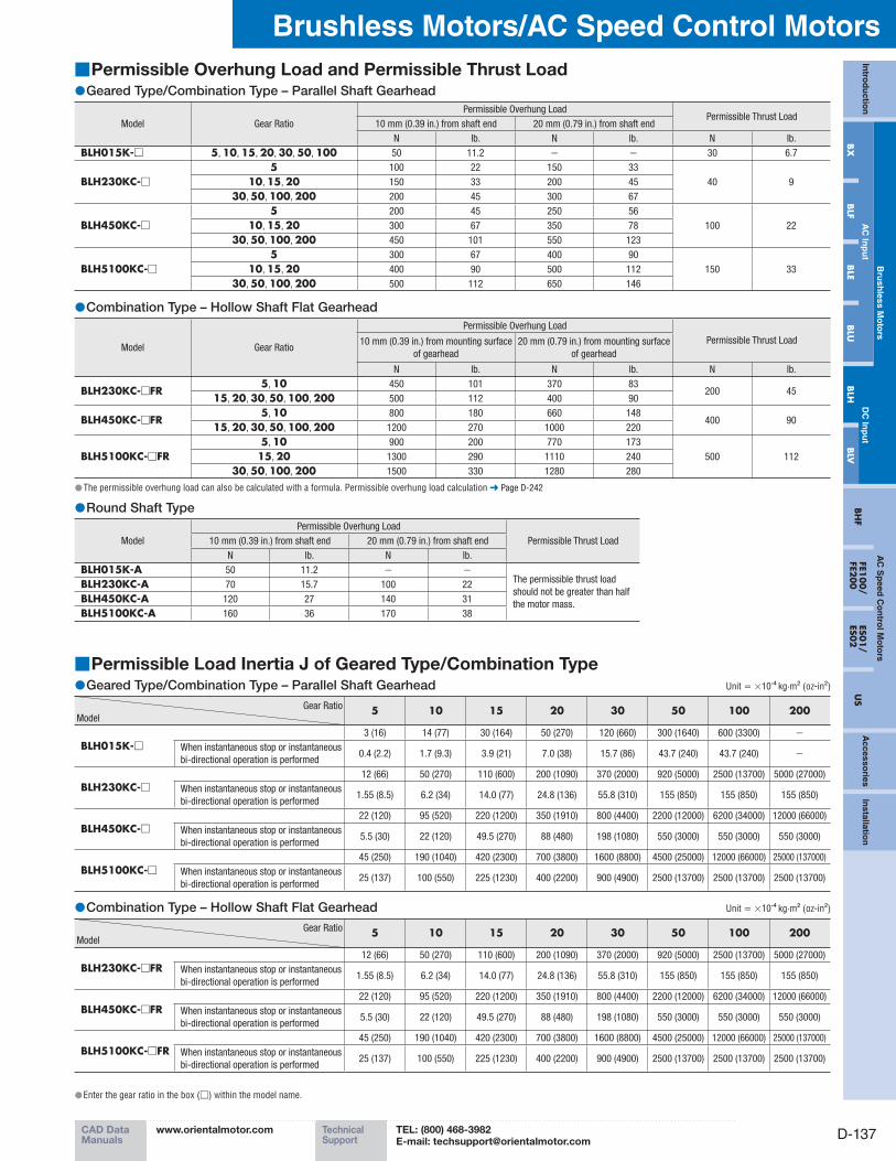
Permissible Overhung Load and Permissible Thrust Load ■Geared Type/Combination Type – Parallel Shaft Gearhead ●
Model Gear Ratio
Permissible Overhung LoadPermissible Thrust Load
10 mm (0.39 in.) from shaft end 20 mm (0.79 in.) from shaft end
N lb. N lb. N lb.
BLH015K-□ 5, 10, 15, 20, 30, 50, 100 50 11.2 − − 30 6.7
BLH230KC-□5 100 22 150 33
40 910, 15, 20 150 33 200 45
30, 50, 100, 200 200 45 300 67
BLH450KC-□5 200 45 250 56
100 2210, 15, 20 300 67 350 78
30, 50, 100, 200 450 101 550 123
BLH5100KC-□5 300 67 400 90
150 3310, 15, 20 400 90 500 112
30, 50, 100, 200 500 112 650 146
Combination Type – Hollow Shaft Flat Gearhead ●
Model Gear Ratio
Permissible Overhung Load
Permissible Thrust Load10 mm (0.39 in.) from mounting surface
of gearhead
20 mm (0.79 in.) from mounting surface
of gearhead
N lb. N lb. N lb.
BLH230KC-□FR5, 10 450 101 370 83
200 4515, 20, 30, 50, 100, 200 500 112 400 90
BLH450KC-□FR5, 10 800 180 660 148
400 9015, 20, 30, 50, 100, 200 1200 270 1000 220
BLH5100KC-□FR5, 10 900 200 770 173
500 11215, 20 1300 290 1110 240
30, 50, 100, 200 1500 330 1280 280
The permissible overhung load can also be calculated with a formula. Permissible overhung load calculation ● ➜ Page D-242
Round Shaft Type ●
Model
Permissible Overhung Load
Permissible Thrust Load10 mm (0.39 in.) from shaft end 20 mm (0.79 in.) from shaft end
N lb. N lb.
BLH015K-A 50 11.2 − −The permissible thrust load
should not be greater than half
the motor mass.
BLH230KC-A 70 15.7 100 22
BLH450KC-A 120 27 140 31
BLH5100KC-A 160 36 170 38
Permissible Load Inertia J of Geared Type/Combination Type ■Geared Type/Combination Type – Parallel Shaft Gearhead ● Unit = ×10-4 kg·m2 (oz-in2)
Gear Ratio
Model5 10 15 20 30 50 100 200
BLH015K-□3 (16) 14 (77) 30 (164) 50 (270) 120 (660) 300 (1640) 600 (3300) −
When instantaneous stop or instantaneous
bi-directional operation is performed0.4 (2.2) 1.7 (9.3) 3.9 (21) 7.0 (38) 15.7 (86) 43.7 (240) 43.7 (240) −
BLH230KC-□12 (66) 50 (270) 110 (600) 200 (1090) 370 (2000) 920 (5000) 2500 (13700) 5000 (27000)
When instantaneous stop or instantaneous
bi-directional operation is performed1.55 (8.5) 6.2 (34) 14.0 (77) 24.8 (136) 55.8 (310) 155 (850) 155 (850) 155 (850)
BLH450KC-□22 (120) 95 (520) 220 (1200) 350 (1910) 800 (4400) 2200 (12000) 6200 (34000) 12000 (66000)
When instantaneous stop or instantaneous
bi-directional operation is performed5.5 (30) 22 (120) 49.5 (270) 88 (480) 198 (1080) 550 (3000) 550 (3000) 550 (3000)
BLH5100KC-□45 (250) 190 (1040) 420 (2300) 700 (3800) 1600 (8800) 4500 (25000) 12000 (66000) 25000 (137000)
When instantaneous stop or instantaneous
bi-directional operation is performed25 (137) 100 (550) 225 (1230) 400 (2200) 900 (4900) 2500 (13700) 2500 (13700) 2500 (13700)
Combination Type – Hollow Shaft Flat Gearhead ● Unit = ×10-4 kg·m2 (oz-in2)
Gear Ratio
Model5 10 15 20 30 50 100 200
BLH230KC-□FR12 (66) 50 (270) 110 (600) 200 (1090) 370 (2000) 920 (5000) 2500 (13700) 5000 (27000)
When instantaneous stop or instantaneous
bi-directional operation is performed1.55 (8.5) 6.2 (34) 14.0 (77) 24.8 (136) 55.8 (310) 155 (850) 155 (850) 155 (850)
BLH450KC-□FR22 (120) 95 (520) 220 (1200) 350 (1910) 800 (4400) 2200 (12000) 6200 (34000) 12000 (66000)
When instantaneous stop or instantaneous
bi-directional operation is performed5.5 (30) 22 (120) 49.5 (270) 88 (480) 198 (1080) 550 (3000) 550 (3000) 550 (3000)
BLH5100KC-□FR45 (250) 190 (1040) 420 (2300) 700 (3800) 1600 (8800) 4500 (25000) 12000 (66000) 25000 (137000)
When instantaneous stop or instantaneous
bi-directional operation is performed25 (137) 100 (550) 225 (1230) 400 (2200) 900 (4900) 2500 (13700) 2500 (13700) 2500 (13700)
Enter the gear ratio in the box ( ● □) within the model name.
PageORIENTAL MOTOR GENERAL CATALOG 2012/2013
D-138 Features D-132 / System Configuration D-133 / Product Line D-134 / Specifications D-134 / Characteristics D-135 Dimensions D-138 / Connection and Operation D-144 / Motor and Driver Combinations D-147
Brushless Motors/BLH Series
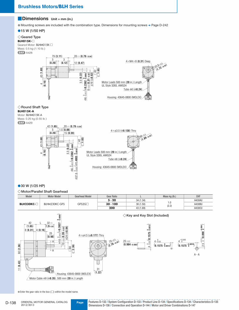
Dimensions ■ Unit = mm (in.)
Mounting screws are included with the combination type. Dimensions for mounting screws ● ➜ Page D-242
15 W (1/50 HP) ●
Geared Type ◇BLH015K-□Geared Motor: BLHM015K-□Mass: 0.5 kg (1.10 lb.)
A428
3 (0.12)
5.5
(0.2
2)
12 (0.47)4×M4×8 (0.31) Deep
43.8±0.5
(1.72±0.02)
4 (
0.1
6)
43 (
1.6
9)
5(0.20)
79 (3.11) 20±1 (0.79±0.04)
8±
0.5
(0.3
1±
0.0
2)
ϕ16 (
ϕ0.6
3)
□42
( □1.6
5)
Motor Leads 500 mm (20 in.) Length
UL Style 3265, AWG24
Housing: 43645-0800 (MOLEX)
Tube ϕ6 (ϕ0.24)
ϕ6
−0.0
12
( ϕ0.2
362
−0
.00
05)
00
Round Shaft Type ◇BLH015K-AMotor: BLHM015K-AMass: 0.25 kg (0.55 lb.)
A429
4 (
0.1
6)
Motor Leads 500 mm (20 in.) Length
UL Style 3265, AWG24
Housing: 43645-0800 (MOLEX)
5.5
(0.2
2)
15 (0.59)5
(0.20)1.5 (0.06)
43 (
1.6
9)
4×ϕ3.5 (ϕ0.138) Thru
48±0.5
(1.89±0.02)
Tube ϕ6 (ϕ0.24)
42 (1.65) 20±1 (0.79±0.04)
□42
( □1.6
5)
ϕ6
−0.0
12
( ϕ0.2
362
−0
.00
05)
00
ϕ37.6
−0.0
25
( ϕ1.4
803
−0
.00
10)
00
30 W (1/25 HP) ●Motor/Parallel Shaft Gearhead ◇
Model Motor Model Gearhead Model Gear Ratio L Mass kg (lb.) DXF
BLH230KC-□ BLHM230KC-GFS GFS2G□
5∼20 34 (1.34)1.0
(2.2)
A430AU
30∼100 38 (1.50) A430BU
200 43 (1.69) A430CU
Key and Key Slot (Included) ◇
Enter the gear ratio in the box ( ● □) within the model name.
A
A−A
A
Housing: 43645-0800 (MOLEX)
31(1.22)
70±0.5
(2.76±0.02)
4×ϕ4.5 (ϕ0.177) Thru
60
( 2.3
6)
11
( 0.4
3)
8 (0.31)
25(0.98)
4 (0.16)
32±1
(1.26±0.04)L42
(1.65)
10
±0
.5( 0
.39
±0
.02)
ϕ24
(ϕ0.9
4)
□60
( □2.3
6)
4−0.03 0
4 0+0.040
ϕ10
−0.0
15
0( ϕ
0.3
937
−0
.00
06)
0
Motor Cable ϕ9 (ϕ0.35), 500 mm (20 in.) Length
25±0.2
(0.984±0.008)
4−
0.0
3 0
( 0.1
575
−0
.00
12)
0
(0.1575−0.0012)0 (0.1575 0 )+0.0016
2.5
0
+0.1
( 0.0
98
0
)+
0.0
04
CAD DataManuals
www.orientalmotor.com Technical Support
TEL: (800) 468-3982E-mail: [email protected]
D-139
Brushless Motors/AC Speed Control MotorsIn
trod
uctio
n
Bru
shless M
oto
rsA
C S
peed
Co
ntro
l Mo
tors
Accesso
riesIn
stallation
AC
Inp
ut
DC
Inp
ut
BH
FFE1
00/
FE200
ES01/
ES02
US
BX
BLF
BLE
BLU
BLH
BLV
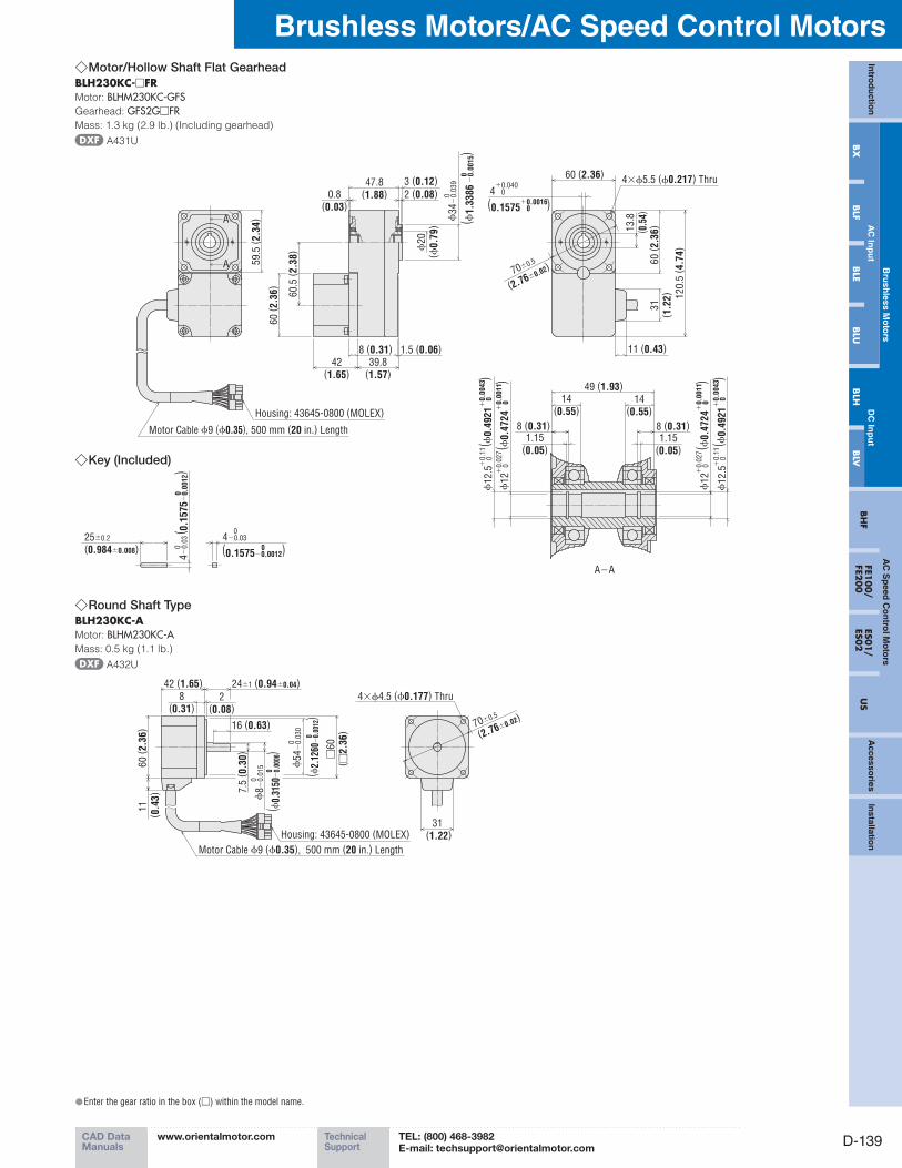
Motor/Hollow Shaft Flat Gearhead ◇BLH230KC-□FRMotor: BLHM230KC-GFSGearhead: GFS2G□FRMass: 1.3 kg (2.9 lb.) (Including gearhead)
A431U
11 (0.43)
A
A−A
59.5
( 2.3
4)A
3 (0.12)
0.8(0.03)
2 (0.08)
8 (0.31)
42(1.65)
60
( 2.3
6)
1.5 (0.06)
39.8(1.57)
47.8(1.88)
60.5
( 2.3
8) ϕ
20
(ϕ0.7
9)
60
( 2.3
6)
31
( 1.2
2)
13.8
( 0.5
4)
120.5
( 4.7
4)
60 (2.36)4×ϕ5.5 (ϕ0.217) Thru
70±0.5
(2.76±0.02)
4 0+0.040
Motor Cable ϕ9 (ϕ0.35), 500 mm (20 in.) Length
Housing: 43645-0800 (MOLEX)
ϕ34
−0.0
39
0
( ϕ1.3
386
−0
.00
15)
0
(0.1575 0 )+0.0016
1.15(0.05)
8 (0.31)
ϕ12
0+
0.0
27( ϕ
0.4
724
0
)+
0.0
011
ϕ12.5
0+
0.1
1( ϕ
0.4
921
0
)+
0.0
043
14(0.55)
14(0.55)
8 (0.31)
49 (1.93)
1.15(0.05)
ϕ12
0+
0.0
27( ϕ
0.4
724
0
)+
0.0
011
ϕ12.5
0+
0.1
1( ϕ
0.4
921
0
)+
0.0
043
Round Shaft Type ◇BLH230KC-AMotor: BLHM230KC-AMass: 0.5 kg (1.1 lb.)
A432U
31 (1.22)
60 (
2.3
6)
11
(0.4
3)
8(0.31)
2(0.08)
16 (0.63)
7.5
(0.3
0)
42 (1.65) 24±1 (0.94±0.04)
□60
( □2.3
6)
70±0.5
(2.76±0.02)
4×ϕ4.5 (ϕ0.177) Thru
Housing: 43645-0800 (MOLEX)
Motor Cable ϕ9 (ϕ0.35), 500 mm (20 in.) Length
ϕ8
−0.0
15
( ϕ0.
3150
−0.
0006
)0
0
ϕ54
−0.0
30
0
( ϕ2.
1260
−0.
0012
)0
Key (Included) ◇
25±0.2
(0.984±0.008)
4−
0.0
3 0
( 0.1
575
−0
.00
12)
0
4−0.03 0
(0.1575−0.0012)0
Enter the gear ratio in the box ( ● □) within the model name.
PageORIENTAL MOTOR GENERAL CATALOG 2012/2013
D-140 Features D-132 / System Configuration D-133 / Product Line D-134 / Specifications D-134 / Characteristics D-135 Dimensions D-138 / Connection and Operation D-144 / Motor and Driver Combinations D-147
Brushless Motors/BLH Series
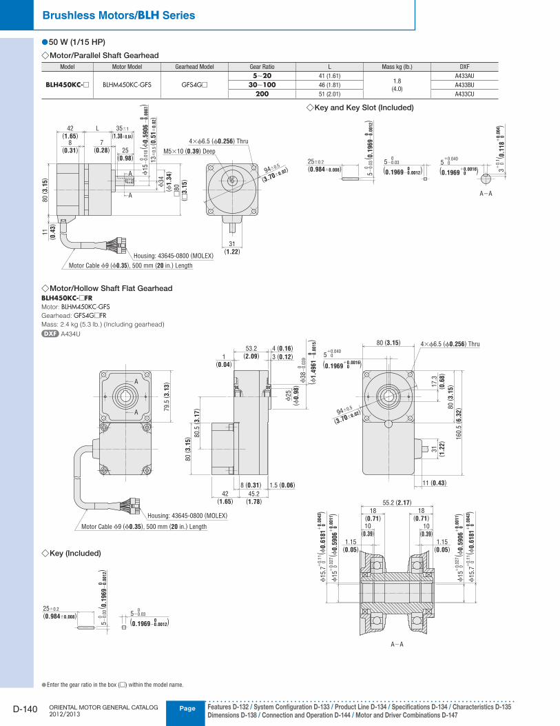
50 W (1/15 HP) ●Motor/Parallel Shaft Gearhead ◇
Model Motor Model Gearhead Model Gear Ratio L Mass kg (lb.) DXF
BLH450KC-□ BLHM450KC-GFS GFS4G□
5∼20 41 (1.61)1.8
(4.0)
A433AU
30∼100 46 (1.81) A433BU
200 51 (2.01) A433CU
(0.1969−0.0012)0
31(1.22)
25±0.2
(0.984±0.008)5−0.03
0
A−AA
A
80
( 3.1
5)
11
( 0.4
3)
L42(1.65)
25(0.98)
8(0.31)
7(0.28)
35±1
(1.38±0.04)
13
±0
.5( 0
.51
±0
.02)
ϕ34
(ϕ1.3
4)
□80
( □3.1
5)
4×ϕ6.5 (ϕ0.256) Thru
94±0.5
(3.70±0.02)
Housing: 43645-0800 (MOLEX)
ϕ15
−0.0
18
0
Motor Cable ϕ9 (ϕ0.35), 500 mm (20 in.) Length
( ϕ0.5
906
−0
.00
07)
0
5−
0.0
3 0
( 0.1
969
−0
.00
12)
0
5 0+0.040
(0.1969 0 )+0.0016
( 0.1
18
0
)+
0.0
04
3 0
+0.1
M5×10 (0.39) Deep
Motor/Hollow Shaft Flat Gearhead ◇BLH450KC-□FRMotor: BLHM450KC-GFSGearhead: GFS4G□FRMass: 2.4 kg (5.3 lb.) (Including gearhead)
A434U
79.5
( 3.1
3)
A−A
A
A
31
( 1.2
2)
1(0.04)
3 (0.12)
53.2(2.09)
4 (0.16)
80.5
( 3.1
7)
80
( 3.1
5)
42(1.65)
45.2(1.78)
ϕ25
(ϕ0.9
8)
80 (3.15)
17.3
( 0.6
8)
160.5
( 6.3
2)
94±0.5
(3.70±0.02)
5 0+0.040
4×ϕ6.5 (ϕ0.256) Thru
80
( 3.1
5)
10(0.39)
10(0.39)
18(0.71)
18(0.71)
55.2 (2.17)
Housing: 43645-0800 (MOLEX)
ϕ38
−0.0
39
0
Motor Cable ϕ9 (ϕ0.35), 500 mm (20 in.) Length
8 (0.31) 1.5 (0.06)
( ϕ1.4
961
−0
.00
15)
0
(0.1969 0 )+0.0016
11 (0.43)
1.15(0.05)
1.15(0.05)
ϕ15
0+
0.0
27( ϕ
0.5
906
0
)+
0.0
011
ϕ15
0+
0.0
27( ϕ
0.5
906
0
)+
0.0
011
ϕ15.7
0+
0.1
1( ϕ
0.6
181
0
)+
0.0
043
ϕ15.7
0+
0.1
1( ϕ
0.6
181
0
)+
0.0
043
Key and Key Slot (Included) ◇
Key (Included) ◇
5−0.03025±0.2
(0.984±0.008)
5−
0.0
3 0
( 0.1
969
−0
.00
12)
0
(0.1969−0.0012)0
Enter the gear ratio in the box ( ● □) within the model name.
CAD DataManuals
www.orientalmotor.com Technical Support
TEL: (800) 468-3982E-mail: [email protected]
D-141
Brushless Motors/AC Speed Control MotorsIn
trod
uctio
n
Bru
shless M
oto
rsA
C S
peed
Co
ntro
l Mo
tors
Accesso
riesIn
stallation
AC
Inp
ut
DC
Inp
ut
BH
FFE1
00/
FE200
ES01/
ES02
US
BX
BLF
BLE
BLU
BLH
BLV
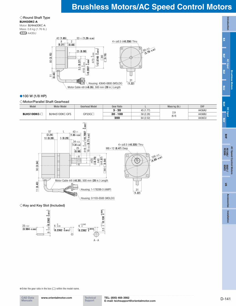
Round Shaft Type ◇BLH450KC-AMotor: BLHM450KC-AMass: 0.8 kg (1.76 lb.)
A435U
100 W (1/8 HP) ●Motor/Parallel Shaft Gearhead ◇
Model Motor Model Gearhead Model Gear Ratio L Mass kg (lb.) DXF
BLH5100KC-□ BLHM5100KC-GFS GFS5G□
5∼20 45 (1.77)2.9
(6.4)
A436AU
30∼100 58 (2.28) A436BU
200 64 (2.52) A436CU
11
(0.4
3)
31(1.22)
4×ϕ6.5 (ϕ0.256) Thru
94±0.5
(3.70±0.02)
42 (1.65)
25 (0.98)
9.5
(0.3
7)
80 (
3.1
5)
2(0.08)
8(0.31)
□80
( □3.1
5)
Motor Cable ϕ9 (ϕ0.35), 500 mm (20 in.) Length
32±1 (1.26±0.04)
ϕ10
−0.0
15
0
( ϕ0.
3937
−0.
0006
)0
Housing: 43645-0800 (MOLEX)
ϕ73
−0.0
30
0
( ϕ2.8
740
−0
.00
12)
0
4×ϕ8.5 (ϕ0.335) Thru
M6×12 (0.47) Deep
104±0.5
(4.09±0.02)
31(1.22)
A
A
90
( 3.5
4)
11
( 0.4
3)
57(2.24)
10 (0.39)
25(0.98)
5 (0.20)
L 42±1
(1.65±0.04)
34±0.5
(1.34±0.02)
ϕ40
(ϕ1.5
7)
ϕ20
(ϕ0.7
9)
□90
( □3.5
4)
18
±0
.5( 0
.71
±0
.02)
Housing: 1-178288-3 (AMP)
Housing: 51103-0500 (MOLEX)
Motor Cable ϕ9 (ϕ0.35), 500 mm (20 in.) Length
ϕ18
−0.0
18
0( ϕ
0.7
087
−0
.00
07)
0
Key and Key Slot (Included) ◇
6−0.03 0
6 0+0.040
A−A
25±0.2
(0.984±0.008)
6−
0.0
3 0
( 0.2
362
−0
.00
12)
0
(0.2362−0.0012)0 (0.2362 0 )+0.0016
3.5
0
+0.1
( 0.1
38
0
)+
0.0
04
Enter the gear ratio in the box ( ● □) within the model name.
PageORIENTAL MOTOR GENERAL CATALOG 2012/2013
D-142 Features D-132 / System Configuration D-133 / Product Line D-134 / Specifications D-134 / Characteristics D-135 Dimensions D-138 / Connection and Operation D-144 / Motor and Driver Combinations D-147
Brushless Motors/BLH Series
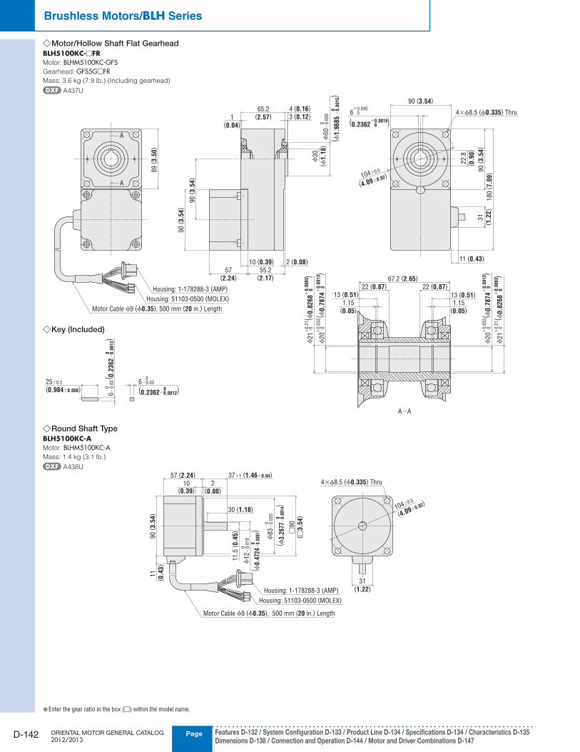
Motor/Hollow Shaft Flat Gearhead ◇BLH5100KC-□FRMotor: BLHM5100KC-GFSGearhead: GFS5G□FRMass: 3.6 kg (7.9 lb.) (Including gearhead)
A437U
(0.2362 0 )+0.0016
89
( 3.5
0)
A
A
31
( 1.2
2)
65.2(2.57)1
(0.04)
90
( 3.5
4)
55.2(2.17)
57(2.24)
10 (0.39)
90
( 3.5
4)
2 (0.08)
ϕ30
(ϕ1.1
8)
90 (3.54)
180
( 7.0
9)
22.8
( 0.9
0)
90
( 3.5
4)
4×ϕ8.5 (ϕ0.335) Thru6 0+0.040
104±0.5
(4.09±0.02)
67.2 (2.65)
13 (0.51) 13 (0.51)
1.15(0.05)
1.15(0.05)
22 (0.87) 22 (0.87)
A−A
Housing: 1-178288-3 (AMP)
Housing: 51103-0500 (MOLEX)
Motor Cable ϕ9 (ϕ0.35), 500 mm (20 in.) Length
ϕ50
−0.0
39
0
3 (0.12)4 (0.16)
( ϕ1.9
685
−0
.00
15)
0
11 (0.43)
ϕ20
0+
0.0
33( ϕ
0.7
874
0
)+
0.0
013
ϕ21
0+
0.2
1( ϕ
0.8
268
0
)+
0.0
083
ϕ20
0+
0.0
33( ϕ
0.7
874
0
)+
0.0
013
ϕ21
0+
0.2
1( ϕ
0.8
268
0
)+
0.0
083
Round Shaft Type ◇BLH5100KC-AMotor: BLHM5100KC-AMass: 1.4 kg (3.1 lb.)
A438U
ϕ12
−0.0
18
0
( ϕ0.
4724
−0.
0007
)0
31(1.22)
4×ϕ8.5 (ϕ0.335) Thru
11
(0.4
3)
2(0.08)
10(0.39)
90 (
3.5
4)
57 (2.24)
11.5
(0.4
5)
30 (1.18)
□90
( □3.5
4)
37±1 (1.46±0.04)
ϕ83
−0.0
35
0
( ϕ3.
2677
−0.
0014
)0
Housing: 51103-0500 (MOLEX)
Housing: 1-178288-3 (AMP)
Motor Cable ϕ9 (ϕ0.35), 500 mm (20 in.) Length
104±0.5
(4.09±0.02)
Key (Included) ◇
6−0.03 0
25±0.2
(0.984±0.008)
6−
0.0
3 0
( 0.2
362
−0
.00
12)
0
(0.2362−0.0012)0
Enter the gear ratio in the box ( ● □) within the model name.
CAD DataManuals
www.orientalmotor.com Technical Support
TEL: (800) 468-3982E-mail: [email protected]
D-143
Brushless Motors/AC Speed Control MotorsIn
trod
uctio
n
Bru
shless M
oto
rsA
C S
peed
Co
ntro
l Mo
tors
Accesso
riesIn
stallation
AC
Inp
ut
DC
Inp
ut
BH
FFE1
00/
FE200
ES01/
ES02
US
BX
BLF
BLE
BLU
BLH
BLV
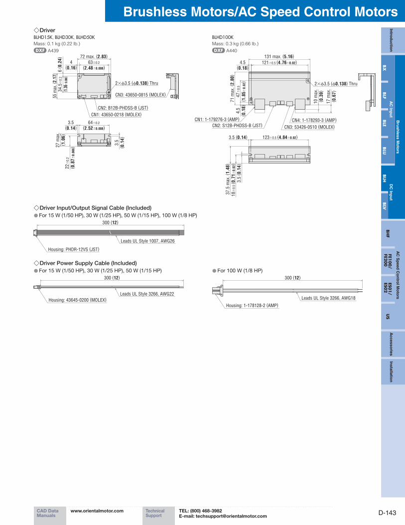
Driver ◇BLHD15K, BLHD30K, BLHD50KMass: 0.1 kg (0.22 lb.)
A439
72 max. (2.83)34.5
±0
.2
( 1.3
6±0.
008)
55 m
ax. (
2.17
)
64±0.2
(2.52±0.008)
22
±0
.2
( 0.8
7±
0.0
08)2
7 m
ax.
( 1.0
6)
3.5(0.14)
3.5
( 0.1
4)
63±0.2
(2.48±0.008)4
(0.16)
6( 0
.24)
2×ϕ3.5 (ϕ0.138) Thru
CN2: B12B-PHDSS-B (JST)
CN1: 43650-0218 (MOLEX)
CN3: 43650-0815 (MOLEX)
Driver Input/Output Signal Cable (Included) ◇For 15 W (1/50 HP), 30 W (1/25 HP), 50 W (1/15 HP), 100 W (1/8 HP) ●
300 (12)
Housing: PHDR-12VS (JST)
Leads UL Style 1007, AWG26
Driver Power Supply Cable (Included) ◇For 15 W (1/50 HP), 30 W (1/25 HP), 50 W (1/15 HP) ●
300 (12)
Housing: 43645-0200 (MOLEX)
Leads UL Style 3266, AWG22
For 100 W (1/8 HP) ●300 (12)
Housing: 1-178128-2 (AMP)
Leads UL Style 3266, AWG18
BLHD100KMass: 0.3 kg (0.66 lb.)
A440
71 m
ax.
( 2.8
0)
4.5
( 0.1
8)
131 max. (5.16)
4.5(0.18)
37.5
max
. ( 1
.48)
3.5
( 0.1
4)
3.5 (0.14)
2×ϕ3.5 (ϕ0.138) Thru
123±0.5 (4.84±0.02)
47
±0
.5
( 1.8
5±
0.0
2)
121±0.5 (4.76±0.02)
18
±0
.5( 0
.71
±0
.02)
10 m
ax.
( 0.3
9)
17 m
ax.
( 0.6
7)
CN2: S12B-PHDSS-B (JST)
CN1: 1-179276-3 (AMP)
CN3: 53426-0510 (MOLEX)
CN4: 1-178293-3 (AMP)
PageORIENTAL MOTOR GENERAL CATALOG 2012/2013
D-144 Features D-132 / System Configuration D-133 / Product Line D-134 / Specifications D-134 / Characteristics D-135 Dimensions D-138 / Connection and Operation D-144 / Motor and Driver Combinations D-147
Brushless Motors/BLH Series
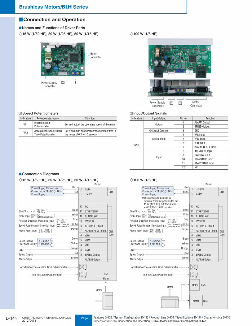
Connection and Operation ■
Names and Functions of Driver Parts ●15 W (1/50 HP), 30 W (1/25 HP), 50 W (1/15 HP) ◇
□2 □1Power Supply
Connector
Motor
Connector
100 W (1/8 HP) ◇
□2 □1Power Supply
Connector
Motor
Connector
□1 Speed Potentiometers
Indication Potentiometer Name Function
VR1Internal Speed
PotentiometerSet and adjust the operating speed of the motor.
VR2Acceleration/Deceleration
Time Potentiometer
Set a common acceleration/deceleration time in
the range of 0.5 to 10 seconds.
□2 Input/Output Signals
Indication Input/Output Pin No. Function
CN2
Output1 ALARM Output
2 SPEED Output
I/O Signal Common 3 GND
Analog Input
4 VRL Input
5 VRM Input
6 VRH Input
Input
7 ALARM-RESET Input
8 INT.VR/EXT Input
9 CW/CCW Input
10 RUN/BRAKE Input
11 START/STOP Input
12 NC
Connection Diagrams ●15 W (1/50 HP), 30 W (1/25 HP), 50 W (1/15 HP) ◇
CN2(I/O)
CN1
ALARM Output
VRM
VRH
ALARM-RESET Input
INT.VR/EXT Input
VRL
CW/CCW
GND
RUN/BRAKE
SPEED Output
START/STOP
NC
GND
+24 V
Acceleration/Deceleration Time Potentiometer
Driver
Internal Speed Potentiometer
1
5
6
7
8
4
9
3
10
2
11
12
2
1
Power Supply Connection
Connected to 24 VDC (±10%)
Power Supply
Black
Red
Black
White
Gray
Light Blue
Purple
Green
Yellow
Orange
Red
Brown
0∼5 VDC1 mA min.
GND
Speed Setting DC Power Supply
Speed Output
Alarm Output
−
+
ON: ResetOFF: NormalAlarm Reset Input
ON: InternalOFF: ExternalSpeed Potentiometer Selection Input
ON: CWOFF: CCWRotation Direction Switching Input
ON: RunOFF: Instantaneous StopBrake Input
ON: StartOFF: StopStart/Stop Input
Motor
CN3
Motor
100 W (1/8 HP) ◇
CN4
CN2(I/O)
CN1
ALARM Output
VRM
VRH
ALARM-RESET Input
INT.VR/EXT Input
VRL
CW/CCW
GND
RUN/BRAKE
SPEED Output
START/STOP
NC
+24 V✽
GND✽
MotorMotor CN3
Motor
Driver
1
5
6
7
8
4
9
3
10
2
11
12
2
1Black
Red
Brown
Red
Orange
Yellow
Green
Purple
Light Blue
Gray
White
Black
Acceleration/Deceleration Time Potentiometer
Internal Speed Potentiometer
0∼5 VDC1 mA min.
GND
Speed Setting DC Power Supply
Speed Output
Alarm Output
−
+
ON: ResetOFF: NormalAlarm Reset Input
ON: InternalOFF: ExternalSpeed Potentiometer Selection Input
ON: CWOFF: CCWRotation Direction Switching Input
ON: RunOFF: Instantaneous StopBrake Input
ON: StartOFF: StopStart/Stop Input
✽The connection position is
different from the position for the
15 W (1/50 HP), 30 W (1/25 HP)
and 50 W (1/15 HP) models.
Power Supply Connection
Connected to 24 VDC (±10%)
Power Supply
CAD DataManuals
www.orientalmotor.com Technical Support
TEL: (800) 468-3982E-mail: [email protected]
D-145
Brushless Motors/AC Speed Control MotorsIn
trod
uctio
n
Bru
shless M
oto
rsA
C S
peed
Co
ntro
l Mo
tors
Accesso
riesIn
stallation
AC
Inp
ut
DC
Inp
ut
BH
FFE1
00/
FE200
ES01/
ES02
US
BX
BLF
BLE
BLU
BLH
BLV
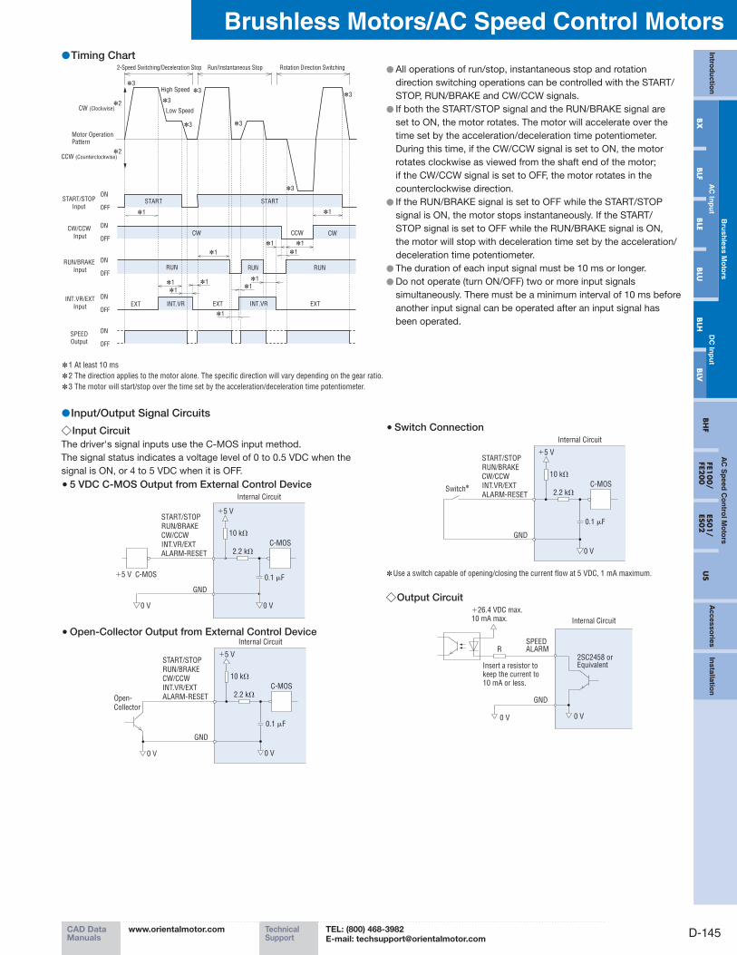
Timing Chart ●2-Speed Switching/Deceleration Stop
High Speed
Low Speed
Run/Instantaneous Stop Rotation Direction Switching
CW (Clockwise)
CCW (Counterclockwise)
ON
OFF
Motor Operation Pattern
START/STOP
Input
CW/CCW
Input
RUN/BRAKE
Input
INT.VR/EXT
Input
START START
CW CCW
RUN RUN RUN
EXT EXTEXT INT.VR INT.VR
CW
✽1 ✽1
✽1
✽1
✽1
✽1✽1
✽1
✽1
✽1
✽1
✽1
ON
OFF
ON
OFF
ON
OFF
ON
OFF
SPEED
Output
✽3
✽3
✽3
✽3
✽3
✽3
✽3
✽2
✽2
Input/Output Signal Circuits ●Input Circuit ◇
The driver's signal inputs use the C-MOS input method.
The signal status indicates a voltage level of 0 to 0.5 VDC when the
signal is ON, or 4 to 5 VDC when it is OFF.
5 VDC C-MOS Output from External Control Device ●
+5 V C-MOS 0.1 μF
2.2 kΩ
GND
+5 V
10 kΩ
START/STOP
RUN/BRAKE
CW/CCW
INT.VR/EXT
ALARM-RESET
C-MOS
Internal Circuit
0 V 0 V
Open-Collector Output from External Control Device ●
Open-
Collector
0 V
0.1 μF
2.2 kΩ
GND
+5 V
10 kΩ
START/STOP
RUN/BRAKE
CW/CCW
INT.VR/EXT
ALARM-RESET
C-MOS
Internal Circuit
0 V
Switch Connection ●
0.1 μF
2.2 kΩ
GND
+5 V
10 kΩ
START/STOP
RUN/BRAKE
CW/CCW
INT.VR/EXT
ALARM-RESET
C-MOS
Internal Circuit
0 V
Switch✽
Use a switch capable of opening/closing the current flow at 5 VDC, 1 mA maximum. ✽
Output Circuit ◇
GND
2SC2458 or Equivalent
Internal Circuit
+26.4 VDC max.10 mA max.
SPEEDALARMR
0 V 0 V
Insert a resistor to keep the current to 10 mA or less.
All operations of run/stop, instantaneous stop and rotation ●direction switching operations can be controlled with the START/
STOP, RUN/BRAKE and CW/CCW signals.
If both the START/STOP signal and the RUN/BRAKE signal are ●set to ON, the motor rotates. The motor will accelerate over the
time set by the acceleration/deceleration time potentiometer.
During this time, if the CW/CCW signal is set to ON, the motor
rotates clockwise as viewed from the shaft end of the motor;
if the CW/CCW signal is set to OFF, the motor rotates in the
counterclockwise direction.
If the RUN/BRAKE signal is set to OFF while the START/STOP ●signal is ON, the motor stops instantaneously. If the START/
STOP signal is set to OFF while the RUN/BRAKE signal is ON,
the motor will stop with deceleration time set by the acceleration/
deceleration time potentiometer.
The duration of each input signal must be 10 ms or longer. ●Do not operate (turn ON/OFF) two or more input signals ●simultaneously. There must be a minimum interval of 10 ms before
another input signal can be operated after an input signal has
been operated.
1 At least 10 ms ✽
2 The direction applies to the motor alone. The specific direction will vary depending on the gear ratio. ✽
3 The motor will start/stop over the time set by the acceleration/deceleration time potentiometer. ✽
PageORIENTAL MOTOR GENERAL CATALOG 2012/2013
D-146 Features D-132 / System Configuration D-133 / Product Line D-134 / Specifications D-134 / Characteristics D-135 Dimensions D-138 / Connection and Operation D-144 / Motor and Driver Combinations D-147
Brushless Motors/BLH Series
SPEED Output ◇The system outputs pulse signals (with a width of 0.3 ms) at a rate of
30 pulses per rotation of the motor output shaft synchronized with
the motor operation.
You can measure the SPEED output frequency and calculate the
motor speed.
T0.3 ms
Motor speed (r/min) =SPEED output frequency [Hz]
30× 60
1
TSPEED output frequency (Hz) =
ALARM Output ◇The ALARM output is normally ON and goes OFF when there is an
alarm.
ALARM-RESET ◇When the motor is stopped, setting this signal ON, then returning it
to OFF resets the alarm.
Please return either the START/STOP input or the RUN/BRAKE input
to OFF before inputting the ALARM-RESET. The ALARM-RESET is
not accepted if both these signals are ON.
Notes
●Output signal is open-collector output, so an external power supply (Vcc) is required.
●Use a power supply of no more than 26.4 VDC and connect a limit resistor (R) so that the
output current does not exceed 10 mA. When using neither the speed output function nor the
alarm output function, this connection is not required.
Speed Setting Method ●Internal Speed Potentiometer ◇
When INT.VR/EXT input is set to ON, the speed can be set with the
internal speed potentiometer.
There is no need for this connection when the internal speed
potentiometer is not used.
Driver
HighSpeed
8
3ON
OFF
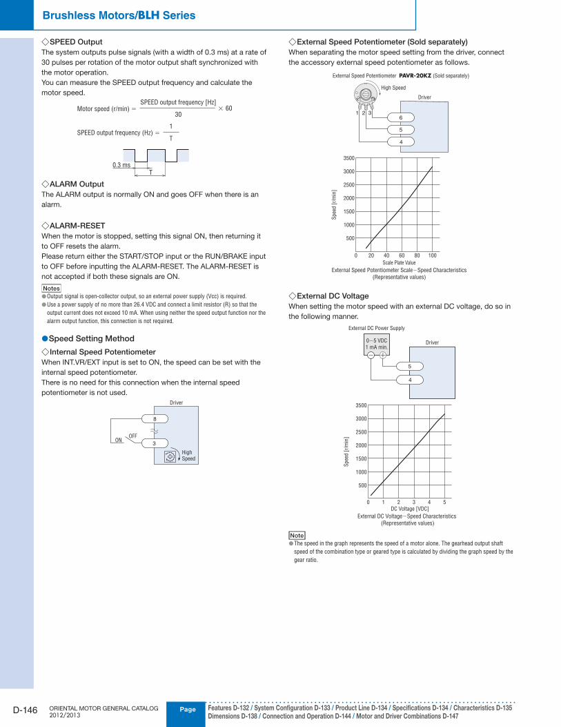
External Speed Potentiometer (Sold separately) ◇When separating the motor speed setting from the driver, connect
the accessory external speed potentiometer as follows.
External Speed Potentiometer PAVR-20KZ (Sold separately)
6
5
4
1 3
High Speed
Driver
21 3
0 20 40 60 80 100
500
1000
1500
2000
3000
3500
External Speed Potentiometer Scale−Speed Characteristics
(Representative values)
Scale Plate Value
Spee
d[r
/min
]
2500
External DC Voltage ◇When setting the motor speed with an external DC voltage, do so in
the following manner.
5
4
0∼5 VDC
1 mA min.Driver
External DC Power Supply
0 1 2 3 4 5
500
1000
1500
2000
3000
3500
External DC Voltage−Speed Characteristics
(Representative values)
DC Voltage [VDC]
Sp
eed
[r/
min
]
2500
Note
●The speed in the graph represents the speed of a motor alone. The gearhead output shaft
speed of the combination type or geared type is calculated by dividing the graph speed by the
gear ratio.
CAD DataManuals
www.orientalmotor.com Technical Support
TEL: (800) 468-3982E-mail: [email protected]
D-147
Brushless Motors/AC Speed Control MotorsIn
trod
uctio
n
Bru
shless M
oto
rsA
C S
peed
Co
ntro
l Mo
tors
Accesso
riesIn
stallation
AC
Inp
ut
DC
Inp
ut
BH
FFE1
00/
FE200
ES01/
ES02
US
BX
BLF
BLE
BLU
BLH
BLV
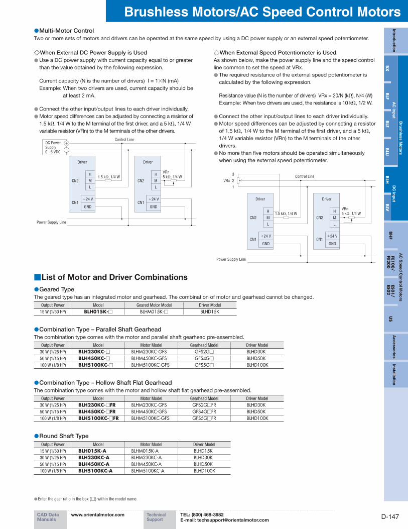
When External DC Power Supply is Used ◇ ● Use a DC power supply with current capacity equal to or greater
than the value obtained by the following expression.
Current capacity (N is the number of drivers) I = 1×N (mA)
Example: When two drivers are used, current capacity should be
at least 2 mA.
Connect the other input/output lines to each driver individually. ● ● Motor speed differences can be adjusted by connecting a resistor of
1.5 kΩ, 1/4 W to the M terminal of the first driver, and a 5 kΩ, 1/4 W
variable resistor (VRn) to the M terminals of the other drivers.
H
MCN2
CN1
L
+24 V
GND
Driver
H
M
L
Driver
Control Line
1.5 kΩ, 1/4 W
DC Power Supply0∼5 VDC
Power Supply Line
+
−
VRn
5 kΩ, 1/4 WCN2
CN1+24 V
GND
When External Speed Potentiometer is Used ◇As shown below, make the power supply line and the speed control
line common to set the speed at VRx.
● The required resistance of the external speed potentiometer is
calculated by the following expression.
Resistance value (N is the number of drivers) VRx = 20/N (kΩ), N/4 (W)
Example: When two drivers are used, the resistance is 10 kΩ, 1/2 W.
Connect the other input/output lines to each driver individually. ● ● Motor speed differences can be adjusted by connecting a resistor
of 1.5 kΩ, 1/4 W to the M terminal of the first driver, and a 5 kΩ,
1/4 W variable resistor (VRn) to the M terminals of the other
drivers.
● No more than five motors should be operated simultaneously
when using the external speed potentiometer.
3
2VRx
1
Control Line
1.5 kΩ, 1/4 W
VRn
5 kΩ, 1/4 WH
M
L
Driver
H
M
L
Driver
Power Supply Line
CN2
CN1+24 V
GND
CN2
CN1+24 V
GND
Multi-Motor Control ●Two or more sets of motors and drivers can be operated at the same speed by using a DC power supply or an external speed potentiometer.
List of Motor and Driver Combinations ■
Geared Type ●The geared type has an integrated motor and gearhead. The combination of motor and gearhead cannot be changed.
Output Power Model Geared Motor Model Driver Model
15 W (1/50 HP) BLH015K-□ BLHM015K-□ BLHD15K
Combination Type – Parallel Shaft Gearhead ●The combination type comes with the motor and parallel shaft gearhead pre-assembled.
Output Power Model Motor Model Gearhead Model Driver Model
30 W (1/25 HP) BLH230KC-□ BLHM230KC-GFS GFS2G□ BLHD30K50 W (1/15 HP) BLH450KC-□ BLHM450KC-GFS GFS4G□ BLHD50K100 W (1/8 HP) BLH5100KC-□ BLHM5100KC-GFS GFS5G□ BLHD100K
Combination Type – Hollow Shaft Flat Gearhead ●The combination type comes with the motor and hollow shaft flat gearhead pre-assembled.
Output Power Model Motor Model Gearhead Model Driver Model
30 W (1/25 HP) BLH230KC-□FR BLHM230KC-GFS GFS2G□FR BLHD30K50 W (1/15 HP) BLH450KC-□FR BLHM450KC-GFS GFS4G□FR BLHD50K100 W (1/8 HP) BLH5100KC-□FR BLHM5100KC-GFS GFS5G□FR BLHD100K
Round Shaft Type ●Output Power Model Motor Model Driver Model
15 W (1/50 HP) BLH015K-A BLHM015K-A BLHD15K30 W (1/25 HP) BLH230KC-A BLHM230KC-A BLHD30K50 W (1/15 HP) BLH450KC-A BLHM450KC-A BLHD50K100 W (1/8 HP) BLH5100KC-A BLHM5100KC-A BLHD100K
Enter the gear ratio in the box ( ● □) within the model name.