Embed Size (px)
Citation preview

EN SP
98319_200910
Maintenance, use and installation manual
Manual de mantenimiento, uso e instalación
Инструкция по монтажу,эксплуатации,техническому обслуживанию
РУС
BT 75 DSPGBT 100 DSPGBT 120 DSPG
BT 180 DSPGBT 250 DSPGBT 300 DSPG

3 / 9298319_200910
- Передначаломэксплуатации горелкивнимательноознакомьтесьс содержаниемданнойброшюры “ПРЕДУПРЕЖДЕНИЯПОЛЬЗОВАТЕЛЮПОБЕЗОПАСНОЙЭКСПЛУАТАЦИИГОРЕЛКИ”, котораявходит в комплект инструкции, и, которая является неотъемлемой и основной частьюизделия.
- Передпускомгорелкииливыполнениемтехобслуживаниянеобходимовнимательнопрочитатьинструкции.- Работы на горелке и в системе должны выполняться квалифицированными работниками.- Перед осуществлением любых работ электрическое питание необходимо выключить.- Работы, выполненные неправильным образом, могут привести к опасным авариям.
- Antes de empezar a usar el quemador lea detenidamente el folleto “ADVERTENCIAS DIRIGIDAS AL USUARIO PARA USAR CON SEGU-RIDAD EL QUEMADOR” que va con el manual de instrucciones y que constituye una parte integrante y esencial del producto.
- Lea atentamente las instrucciones antes de poner en funcionamento los quemadores y efectuar las tareas de mantenimiento.- Los trabajos que se efectúen al quemador y a la instalación deben ser efectuados sólamente por personal cualificado.- La alimentación eléctrica de la instalación se debe desconectar antes de iniciar los trabajos.- Si los trabajos no son efectuados correctamente se corre el riesgo de que se produzcan accidentes peligrosos.
- Before using the burner for the first time please carefully read the chapter “WARNINGS NOTES FOR THE USER : HOW TO USE THE BURNER SAFELY” in this instruction manual, which is an integral and essential part of the product.
- The works on the burner and on the esystem have to be carried out only by competent people.- Read carefully the instructions before starting the burner and service it.- The system electric feeding must be disconnected before starting working on it.- If the works are not carried out correctly it is possible to cause dangerous accidents.
ENGLISH
ESPAÑOL
РУССКИЙ


ENGLISH
5 / 3298319_200910
Statement of ConformityWe hereby declare under our own responsibility, that our “CE” marked products Series:Sparkgas…; BTG…; BGN…; TBG...;Minicomist…; Comist…; RiNOx…, BT…; BTL…; TBL...; GI…; GI…Mist; PYR…; TS…Description:domestic and industrial blown air burners fired by gas, oil and dual fuel respect the minimal regulation of the European Directives: • 90/396/EEC (G.A.D)• 92/42/EEC (B.E.D)• 89/336/EEC (E.M.C. Directive)• 73/23/EEC (Low Voltage Directive)• 98/37 EEC (Machinery Directive) and have been designed and tested in accordance with the European Standards:• EN 676 (gas and dual fuel, gas side)• EN 267 (light oil and dual fuel, oil side)
- EN 60335-1:2001:A1:2004+A11:2004 +A2:2006- EN 60335-2-102:2006- EN 50165:1997:A1:2001- EN 55014-1:2000 + A1:2001+A2:2002- EN 55014-2:1997 + A1:2001- EN 50366:2004 + A1:2006 - EN 61000-3-2:2000 + A2:2005
Surveillance accordingly Gas Appliances Directive 90/396/EEC made by: CE0085 - DVGW
The Vice President and Managing Director: Dr. Riccardo Fava
! Important / note i Information I Warning / Attention
INDEXAIR REGULATION SERVOMOTOR ...................................................................................................................................................................19 APPLICATION OF THE BURNER TO BOILER ..................................................................................................................................................11CONTROL BOx ..................................................................................................................................................................................................20DESCRIPTION OF OPERATION WITH LIGHT OIL ...........................................................................................................................................13ELECTRICAL CONNECTIONS ..........................................................................................................................................................................11ESQUEMA ELECTRICO ....................................................................................................................................................................................99FUEL FEEDING HYDRAULIC DIAGRAM ..........................................................................................................................................................12FUEL FEED SYSTEM ........................................................................................................................................................................................11NOZZLE FLOW-RATE TABLE FOR LIGHT OIL .................................................................................................................................................31REGULATION OF THE COMBUSTION HEAD ..................................................................................................................................................17STARTING UP AND REGULATION WITH LIGHT OIL .......................................................................................................................................16TECHNICAL DATA .............................................................................................................................................................................................8WARNING NOTES FOR THE USER HOW TO USE THE BURNER SAFELY ..................................................................................................6

ENGLISH
6 / 3298319_200910
I WARNING NOTES FOR THE USER HOW TO
USE THE BURNER SAFELYFOREWORD These warning notes are aimed at ensuring the safe use of the compo-nents of heating systems for civil use and the production of hot water. They indicate how to act to avoid the essential safety of the components being compromised by incorrect or erroneous installation and by improper or unreasonable use. The warning notes provided in this guide also seek to make the consumer more aware of safety problems in general, using necessarily technical but easily understood language. The manufacturer is not liable contractually or extra contractually for any damage caused by errors in installation and in use, or where there has been any failure to follow the manufacturer’s instructions.
GENERAL WARNING NOTES • The instruction booklet is an integral and essential part of the product
and must be given to the user. Carefully read the warnings in the bo-oklet as they contain important information regarding safe installation, use and maintenance. Keep the booklet to hand for consultation when needed.
• Equipment must be installed in accordance with current regulations, with the manufacturer’s instructions and by qualified technicians. By the term ‘qualified technicians’ is meant persons that are competent in the field of heating components for civil use and for the production of hot water and, in particular, assistance centres authorised by the manu-facturer. Incorrect installation may cause damage or injury to persons, animals or things. The manufacturer will not in such cases be liable.
• After removing all the packaging make sure the contents are complete and intact. If in doubt do not use the equipment and return it to the supplier. The packaging materials (wooden crates, nails, staples, plastic bags, expanded polystyrene, etc.) must not be left within reach of chil-dren as they may be dangerous to them. They should also be collected and disposed on in suitably prepared places so that they do no pollute the environment.
• Before carrying out any cleaning or maintenance, switch off the equi-pment at the mains supply, using the system’s switch or shut-off sy-stems.
• If there is any fault or if the equipment is not working properly, de-ac-tivate the equipment and do not attempt to repair it or tamper with it directly. In such case get in touch with only qualified technicians. Any product repairs must only be carried out by BALTUR authorised assi-stance centres using only original spare parts. Failure to act as above may jeopardise the safety of the equipment. To ensure the efficiency and correct working of the equipment, it is essential to have periodic maintenance carried out by qualified technicians following the manufac-turer’s instructions.
• If the equipment is sold or transferred to another owner or if the owner moves and leaves the equipment, make sure that the booklet always goes with the equipment so it can be consulted by the new owner and/or installer.
• For all equipment with optionals or kits (including electrical), only origi-nal accessories must be used.
BURNERS • This equipment must be used only for its expressly stated use: applied
to boilers, hot air boilers, ovens or other similar equipment and not exposed to atmospheric agents. Any other use must be regarded as improper use and hence dangerous.
• The burner must be installed in a suitable room that has ventilation in accordance with current regulations and in any case sufficient to ensure correct combustion
• Do not obstruct or reduce the size of the burner’ air intake grills or the ventilation openings for the room where a burner or a boiler is installed or dangerous mixtures of toxic and explosive gases may form.
• Before connecting the burner check that the details on the plate corre-spond to those of the utility supplies (electricity, gas, light oil or other fuel).
• Do not touch hot parts of the burner. These, normally in the areas near to the flame and any fuel pre-heating system, become hot when the equipment is working and stay hot for some time after the burner has stopped.
• If it is decided not to use the burner any more, the following actions must be performed by qualified technicians:
a) Switch off the electrical supply by disconnecting the power cable from the master switch.
b) Cut off the fuel supply using the shut-off valve and remove the control wheels from their position.
c) Render harmless any potentially dangerous parts.Special warning notes • Check that the person who carried out the installation of the burner fixed
it securely to the heat generator so that the flame is generated inside the combustion chamber of the generator itself.
• Before starting up the burner, and at least once a year, have qualified technicians perform the following operations: a) Set the burner fuel capacity to the power required by the heat ge-
nerator.b) Adjust the combustion air flow to obtain combustion yield of at least
the minimum set by current regulations.c) Carry out a check on combustion to ensure the production of no-
xious or polluting unburnt gases does not exceed limits permitted by current regulations.
d) Check the adjustment and safety devices are working properly. e) Check the efficiency of the combustion products exhaust duct. f) Check at the end of the adjustments that all the adjustment devices
mechanical securing systems are properly tightened. g) Make sure that the use and maintenance manual for the burner is
in the boiler room.• If the burner repeatedly stops in lock-out, do not keep trying to manually
reset but call a qualified technicians to sort out the problem.• The running and maintenance of the equipment must only be carried
out by qualified technicians, in compliance with current regulations.

ENGLISH
7 / 3298319_200910
I WARNING NOTES FOR THE USER HOW TO
USE THE BURNER SAFELYELECTRICAL SUPPLY• The equipment is electrically safe only when it is correctly connected to an
efficient ground connection carried out in accordance with current safety regulations. It is necessary to check this essential safety requirement. If in doubt, call for a careful electrical check by a qualified technicians, since the manufacturer will not be liable for any damage caused by a poor ground connection.
• Have qualified technicians check that the wiring is suitable for the maximum power absorption of the equipment, as indicated in the technical plate, making sure in particular that the diameter of cables is sufficient for the equipment’s power absorption.
• Adapters, multiple plugs and extension cables may not be used for the equipment’s power supply.
• An ominpolar switch in accordance with current safety regulations is required for the mains supply connection.
• The electrical supply to the burner must have neutral to ground connection. If the ionisation current has control with neutral not to ground it is essential to make a connection between terminal 2 (neutral) and the ground for the RC circuit.
• The use of any components that use electricity means that certain fundamental rules have to followed, including the following:
- do not touch the equipment with parts of the body that are wet or damp or with damp feet
- do not pull on electrical cables - do not leave the equipment exposed to atmospheric agents (such as
rain or sun etc.) unless there is express provision for this. - do not allow the equipment to be used by children or inexpert
persons. • The power supply cable for the equipment not must be replaced by the
user. If the cable gets damaged, switch off the equipment, and call only on qualified technicians for its replacement.
• If you decide not to use the equipment for a while it is advisable to switch off the electrical power supply to all components in the system that use electricity (pumps, burner, etc.).
GAS, LIGHT OIL, OR OTHER FUEL SUPPLIES General warning notes • Installation of the burner must be carried out by qualified technicians
and in compliance with current law and regulations, since incorrect installation may cause damage to person, animals or things, for which damage the manufacturer shall not can be held responsible.
• Before installation it is advisable to carry out careful internal cleaning of all tubing for the fuel feed system to remove any residues that could jeopardise the proper working of the burner.
• For first start up of the equipment have qualified technicians carry out the following checks:
• If you decide not to use the burner for a while, close the tap or taps that supply the fuel.
Special warning notes when using gas • Have qualified technicians check the following: a) that the feed line and the train comply with current law and
regulations. b) that all the gas connections are properly sealed.• Do not use the gas pipes to ground electrical equipment. • Do not leave the equipment on when it is not in use and always close
the gas tap.• If the user of is away for some time, close the main gas feed tap to the
burner.• If you smell gas: a) do not use any electrical switches, the telephone or any other object
that could produce a spark; b) immediately open doors and windows to create a current of air that
will purify the room; c) close the gas taps; d) ask for the help of qualified technicians.
• Do not block ventilation openings in the room where there is gas equipment or dangerous situations may arise with the build up of toxic and explosive mixtures.
FLUES FOR HIGH EFFICIENCY BOILERS AND SIMILAR It should be pointed out that high efficiency boilers and similar discharge combustion products (fumes) at relatively low temperatures into the flue. In the above situation, traditional flues (in terms of their diameter and heat insulation) may be suitable because the significant cooling of the combustion products in these permits temperatures to fall even below the condensation point. In a flue that works with condensation there is soot at the point the exhaust reaches the atmosphere when burning light oil or heavy oil or the presence of condensate water along the flue itself when gas is being burnt (methane, LPG, etc.). Flues connected to high efficiency boilers and similar must therefore be of a size (section and heat insulation) for the specific use to avoid such problems as those described above.
ENGLISH
8 / 3298319_200910
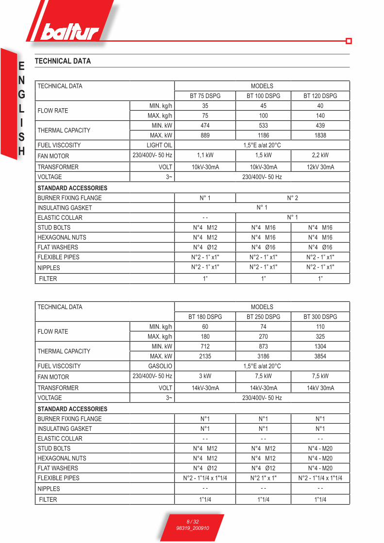
TECHNICAL DATA MODELSBT 75 DSPG BT 100 DSPG BT 120 DSPG
FLOW RATE MIN. kg/h 35 45 40 MAX. kg/h 75 100 140
THERMAL CAPACITY MIN. kW 474 533 439 MAX. kW 889 1186 1838
FUEL VISCOSITY LIGHT OIL 1,5°E a/at 20°C FAN MOTOR 230/400V- 50 Hz 1,1 kW 1,5 kW 2,2 kW
TRANSFORMER VOLT 10kV-30mA 10kV-30mA 12kV 30mAVOLTAGE 3~ 230/400V- 50 HzSTANDARD ACCESSORIESBURNER FIXING FLANGE N° 1 N° 2INSULATING GASKET N° 1ELASTIC COLLAR - - N° 1STUD BOLTS N°4 M12 N°4 M16 N°4 M16HEXAGONAL NUTS N°4 M12 N°4 M16 N°4 M16FLAT WASHERS N°4 Ø12 N°4 Ø16 N°4 Ø16FLEXIBLE PIPES N°2 - 1” x1" N°2 - 1” x1" N°2 - 1” x1"NIPPLES N°2 - 1” x1" N°2 - 1” x1" N°2 - 1” x1"
FILTER 1” 1” 1”
TECHNICAL DATA MODELSBT 180 DSPG BT 250 DSPG BT 300 DSPG
FLOW RATE MIN. kg/h 60 74 110 MAX. kg/h 180 270 325
THERMAL CAPACITY MIN. kW 712 873 1304 MAX. kW 2135 3186 3854
FUEL VISCOSITY GASOLIO 1,5°E a/at 20°C FAN MOTOR 230/400V- 50 Hz 3 kW 7,5 kW 7,5 kW
TRANSFORMER VOLT 14kV-30mA 14kV-30mA 14kV 30mAVOLTAGE 3~ 230/400V- 50 HzSTANDARD ACCESSORIESBURNER FIXING FLANGE N°1 N°1 N°1INSULATING GASKET N°1 N°1 N°1ELASTIC COLLAR - - - - - - STUD BOLTS N°4 M12 N°4 M12 N°4 - M20HEXAGONAL NUTS N°4 M12 N°4 M12 N°4 - M20FLAT WASHERS N°4 Ø12 N°4 Ø12 N°4 - M20FLEXIBLE PIPES N°2 - 1”1/4 x 1"1/4 N°2 1" x 1" N°2 - 1”1/4 x 1"1/4NIPPLES - - - - - -
FILTER 1”1/4 1”1/4 1”1/4
TECHNICAL DATA

ENGLISH
9 / 3298319_200910
1 - Pump2 - Pressure regulator valve3 - Modulator4 - Photoresistance5 - Ignition transformer6 - Fan motor
7 - Combustion head8 - Insulating gasket9 - Burner fixing flanges10 - Combustion head control knob11 - Electric board12 - Electromagnet
N° 0002270035DIMENSIONS
BT 100 - 120 DSPG BT 75 - 180 - 250 - 300 DSPG
MOD. A A1 A2 B B1 B2 C D E F I I1 L M N MIN MAX Ø ØBT 75 DSPG 595 310 385 510 365 145 1215 130 ÷ 450 205 160 260 260 225 ÷ 300 M12 170BT 100 DSPG 670 330 340 525 365 160 1415 210 ÷ 400 230 195 320 - 276 M16 240BT 120 DSPG 770 390 380 610 450 160 1415 155 ÷ 500 230 195 320 - 276 M16 240BT 180 DSPG 815 390 425 650 450 200 1700 200 ÷ 535 260 220 320 320 280÷370 M12 230BT 250 DSPG 1000 520 480 740 580 160 1700 235 ÷ 560 260 220 320 320 280÷370 M12 230BT 300 DSPG 1000 520 480 800 580 220 1900 245 ÷ 605 360 275 440 440 400÷540 M20 365
ENGLISH
10 / 3298319_200910
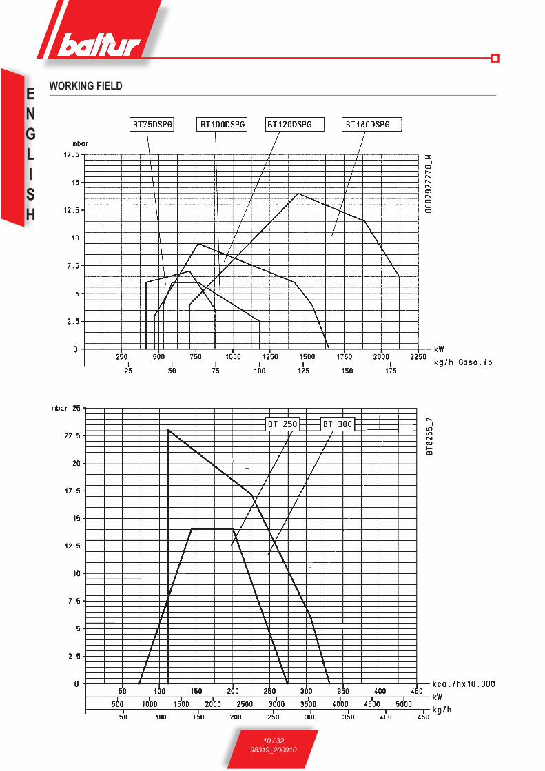
WORKING FIELD
ENGLISH
11 / 3298319_200910
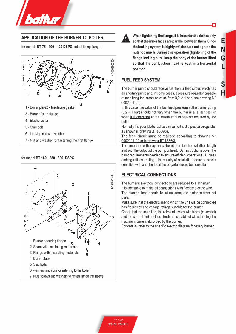
! When tightening the flange, it is important to do it evenly so that the inner faces are parallel between them. Since the locking system is highly efficient, do not tighten the nuts too much. During this operation (tightening of the flange locking nuts) keep the body of the burner lifted so that the combustion head is kept in a horizontal position.
FUEL FEED SYSTEMThe burner pump should receive fuel from a feed circuit which has an ancillary pump and, in some cases, a pressure regulator capable of modifying the pressure value from 0,2 to 1 bar (see drawing N° 0002901120).In this case, the value of the fuel feed pressure at the burner pump (0,2 ÷ 1 bar) should not vary when the burner is at a standstill or when it is operating at the maximum fuel delivery required by the boiler.Normally it is possible to realise a circuit without a pressure regulator as shown in drawing BT 8666/3). The feed circuit must be realized according to drawing N° 0002901120 or to drawing BT 8666/3.The dimension of the pipelines should be in function with their length and with the output of the pump utilized. Our instructions cover the basic requirements needed to ensure efficient operations. All rules and regulations existing in the country of installation should be strictly complied with and the local fire brigade should be consulted.
ELECTRICAL CONNECTIONSThe burner’s electrical connections are reduced to a minimum.It is advisable to make all connections with flexible electric wire.The electric lines should be at an adequate distance from hot parts.Make sure that the electric line to which the unit will be connected has frequency and voltage ratings suitable for the burner.Check that the main line, the relevant switch with fuses (essential) and the current limiter (if required) are capable of with standing the maximum current absorbed by the burner.For details, refer to the specific electric diagram for every burner.
APPLICATION OF THE BURNER TO BOILER
for model BT 75 - 100 - 120 DSPG (steel fixing flange)
1 - Boiler plate2 - Insulating gasket3 - Burner fixing flange4 - Elastic collar5 - Stud bolt6 - Locking nut with washer7 - Nut and washer for fastening the first flange
for model BT 180 - 250 - 300 DSPG
N° 00
0293
3340
N° 00
0293
3330
1 Burner securing flange2 Seam with insulating materials3 Flange with insulating materials4 Boiler plate5 Stud bolts, 6 washers and nuts for astening to the boiler7 Nuts screws and washers to fasten flange the sleeve

ENGLISH
12 / 3298319_200910
N° 0002901120rev.: 19/02/2002
N° BT 8666/3DIAGRAM OF PIPES OF FEED SYSTEM FOR LIGHT OIL BURNERS WITH MAXIMUM NOMINAL VISCOSITY (5 °E at 50 °C)
The combustible recovery and degasifier tanks (diameter ~ 150, height ~ 400) should be installed as near as possible to the burner and should be about 0,5 m. higher with respect to the burner's pump.
FUEL FEEDING HYDRAULIC DIAGRAM FOR ONE OR MORE LIGHT OIL BURNERS WITH MAXIMUM NOMINAL VISCOSITY (5 °E at 50 °C) FROM 75 TO 300 DSPG
The combustible recovery and degasifier tanks (diameter ~ 150, height ~ 400) should be installed as near as possible to the burner and should be about 0,5 m. higher with respect to the burner's pump.
1 Main cictern2 Filter3 Circulation pump4 Water and system drain6 Fuel recovery and degasifier7 One-way valve8 By-pass (usually closed)9 Feeding circuit presure regulator
adjustment range between 0.2 and 1 bar 10 Pressure gauge (0 - 4 bar)
1 Main cictern2 Filter3 Circulation pumps4 Water and system drain5 Air-gas drain usually closed6 Fuel recovery and degasifier7 One-way valve8 By-pass (usually closed)
AL B
RUCI
ATOR
E
AL B
RUCI
ATOR
E
AL B
RUCI
ATOR
E
ENGLISH
13 / 3298319_200910
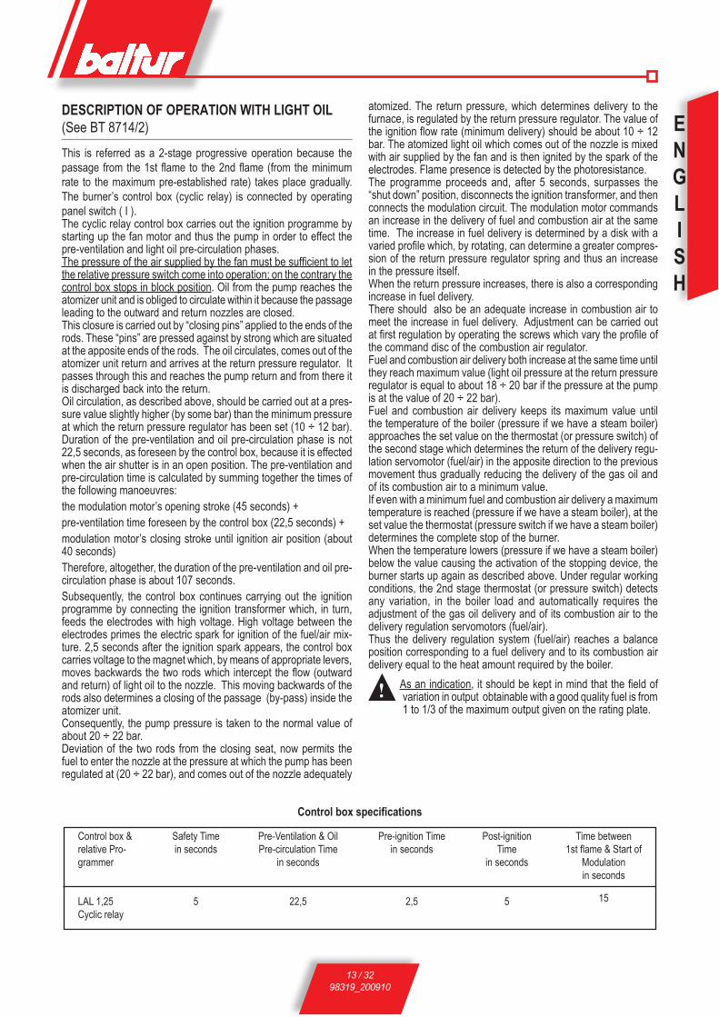
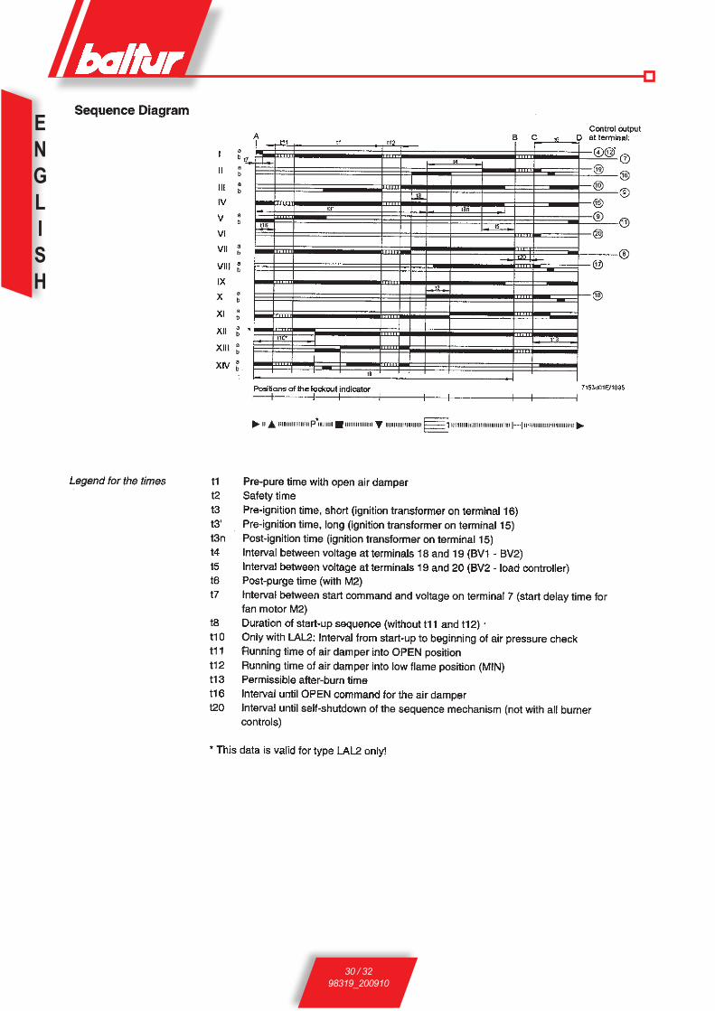
DESCRIPTION OF OPERATION WITH LIGHT OIL (See BT 8714/2)This is referred as a 2-stage progressive operation because the passage from the 1st flame to the 2nd flame (from the minimum rate to the maximum pre-established rate) takes place gradually. The burner’s control box (cyclic relay) is connected by operating panel switch ( I ).The cyclic relay control box carries out the ignition programme by starting up the fan motor and thus the pump in order to effect the pre-ventilation and light oil pre-circulation phases.The pressure of the air supplied by the fan must be sufficient to let the relative pressure switch come into operation; on the contrary the control box stops in block position. Oil from the pump reaches the atomizer unit and is obliged to circulate within it because the passage leading to the outward and return nozzles are closed.This closure is carried out by “closing pins” applied to the ends of the rods. These “pins” are pressed against by strong which are situated at the apposite ends of the rods. The oil circulates, comes out of the atomizer unit return and arrives at the return pressure regulator. It passes through this and reaches the pump return and from there it is discharged back into the return.Oil circulation, as described above, should be carried out at a pres-sure value slightly higher (by some bar) than the minimum pressure at which the return pressure regulator has been set (10 ÷ 12 bar). Duration of the pre-ventilation and oil pre-circulation phase is not 22,5 seconds, as foreseen by the control box, because it is effected when the air shutter is in an open position. The pre-ventilation and pre-circulation time is calculated by summing together the times of the following manoeuvres:the modulation motor’s opening stroke (45 seconds) +pre-ventilation time foreseen by the control box (22,5 seconds) +modulation motor’s closing stroke until ignition air position (about 40 seconds)Therefore, altogether, the duration of the pre-ventilation and oil pre-circulation phase is about 107 seconds.Subsequently, the control box continues carrying out the ignition programme by connecting the ignition transformer which, in turn, feeds the electrodes with high voltage. High voltage between the electrodes primes the electric spark for ignition of the fuel/air mix-ture. 2,5 seconds after the ignition spark appears, the control box carries voltage to the magnet which, by means of appropriate levers, moves backwards the two rods which intercept the flow (outward and return) of light oil to the nozzle. This moving backwards of the rods also determines a closing of the passage (by-pass) inside the atomizer unit.Consequently, the pump pressure is taken to the normal value of about 20 ÷ 22 bar.Deviation of the two rods from the closing seat, now permits the fuel to enter the nozzle at the pressure at which the pump has been regulated at (20 ÷ 22 bar), and comes out of the nozzle adequately
Control box & relative Pro-grammer
LAL 1,25Cyclic relay
Safety Time in seconds
5
Pre-Ventilation & Oil Pre-circulation Time
in seconds
22,5
Pre-ignition Timein seconds
2,5
Post-ignitionTime
in seconds
5
Time between1st flame & Start of
Modulation in seconds
15
Control box specifications
atomized. The return pressure, which determines delivery to the furnace, is regulated by the return pressure regulator. The value of the ignition flow rate (minimum delivery) should be about 10 ÷ 12 bar. The atomized light oil which comes out of the nozzle is mixed with air supplied by the fan and is then ignited by the spark of the electrodes. Flame presence is detected by the photoresistance.The programme proceeds and, after 5 seconds, surpasses the “shut down” position, disconnects the ignition transformer, and then connects the modulation circuit. The modulation motor commands an increase in the delivery of fuel and combustion air at the same time. The increase in fuel delivery is determined by a disk with a varied profile which, by rotating, can determine a greater compres-sion of the return pressure regulator spring and thus an increase in the pressure itself.When the return pressure increases, there is also a corresponding increase in fuel delivery.There should also be an adequate increase in combustion air to meet the increase in fuel delivery. Adjustment can be carried out at first regulation by operating the screws which vary the profile of the command disc of the combustion air regulator.Fuel and combustion air delivery both increase at the same time until they reach maximum value (light oil pressure at the return pressure regulator is equal to about 18 ÷ 20 bar if the pressure at the pump is at the value of 20 ÷ 22 bar).Fuel and combustion air delivery keeps its maximum value until the temperature of the boiler (pressure if we have a steam boiler) approaches the set value on the thermostat (or pressure switch) of the second stage which determines the return of the delivery regu-lation servomotor (fuel/air) in the apposite direction to the previous movement thus gradually reducing the delivery of the gas oil and of its combustion air to a minimum value.If even with a minimum fuel and combustion air delivery a maximum temperature is reached (pressure if we have a steam boiler), at the set value the thermostat (pressure switch if we have a steam boiler) determines the complete stop of the burner.When the temperature lowers (pressure if we have a steam boiler) below the value causing the activation of the stopping device, the burner starts up again as described above. Under regular working conditions, the 2nd stage thermostat (or pressure switch) detects any variation, in the boiler load and automatically requires the adjustment of the gas oil delivery and of its combustion air to the delivery regulation servomotors (fuel/air).Thus the delivery regulation system (fuel/air) reaches a balance position corresponding to a fuel delivery and to its combustion air delivery equal to the heat amount required by the boiler.
! As an indication, it should be kept in mind that the field of variation in output obtainable with a good quality fuel is from 1 to 1/3 of the maximum output given on the rating plate.
ENGLISH
14 / 3298319_200910
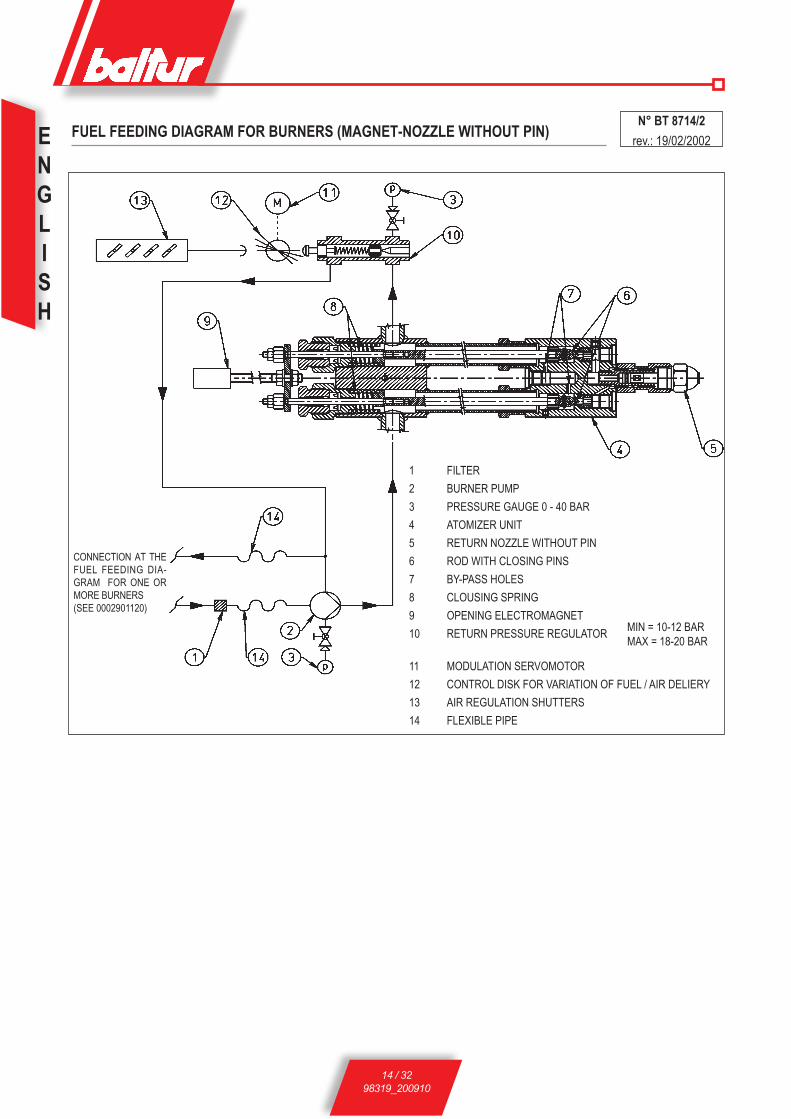
FUEL FEEDING DIAGRAM FOR BURNERS (MAGNET-NOZZLE WITHOUT PIN)N° BT 8714/2
rev.: 19/02/2002
1 FILTER2 BURNER PUMP3 PRESSURE GAUGE 0 - 40 BAR4 ATOMIZER UNIT5 RETURN NOZZLE WITHOUT PIN6 ROD WITH CLOSING PINS7 BY-PASS HOLES8 CLOUSING SPRING9 OPENING ELECTROMAGNET10 RETURN PRESSURE REGULATOR MIN = 10-12 BAR
MAx = 18-20 BAR
11 MODULATION SERVOMOTOR12 CONTROL DISK FOR VARIATION OF FUEL / AIR DELIERY13 AIR REGULATION SHUTTERS14 FLEXIBLE PIPE
CONNECTION AT THE FUEL FEEDING DIA-GRAM FOR ONE OR MORE BURNERS(SEE 0002901120)

ENGLISH
15 / 3298319_200910
DIAGRAM OF A DISMANTLED ( C.B. ) CHARLES BERGONZO NOZZLE (WITHOUT PIN)
N BT
9353
/1
Nozzle ID.:Flow rate kg/hSpray angle (30° - 45° - 60° - 80°)Flow ratio (1/3 = B3 - 1/5 = B5)
Viton O-ring (oil and teperature resistant)
Fuel outlet
Fuel return hole
Fuel inletFuel return
Air turbolence chambre
! For the nozzle to operate properly, its "return" section must never be completely closed. This is achived by regulating where the burner is started up for the first time. In practice, when the nozzle is operating at the maximum flow rate, the difference in pressure between the "delivery" (pump pressure) and "return" (pressure at the return pressure regulator) pressure (running to and from the nozzle) must be at least 2 ÷ 3 bar.
Example: Pump pressure 20 bar Pump pressure 22 bar Return pressure 20 - 2 = 18 bar Return pressure 22 - 3 = 19 bar Return pressure 20 - 3 = 17 bar Return pressure 22 - 2 = 20 bar
N° 00
0290
0580
BALTUR PUMP MODEL BT.....
Suction 1/4” Vacuum-meter connection
Return
Pump plate
Delivery (nozzle)
1/4” Pressure gauge connection
Heating element seal
Pump pressure regulation (20 ÷ 22 bar)
Suction
Return
Delivery (nozzle)
Pump plate
1/4” Vacuum-meter connection
Heating element seal
1/4” Pressure gauge connectionPump pressure regulation (20 ÷ 22 bar)

ENGLISH
16 / 3298319_200910
STARTING UP AND REGULATION WITH LIGHT OIL1) Check that the characteristics of the nozzle (delivery and
spray angle) are suitable for the furnace (see BT 9353/1). If not, replace it.
2) Check that there is fuel in the cistern and that it is, at least visually; suitable for the burner.
3) Check that there is water in the boiler and that the system’s gate valves are open.
4) Check, with absolute certainty, that the discharge of combustion products can take place freely (boiler and chimney lock-gates should be open).
5) Make sure that the voltage of the electric line to which the bur-ner is to be connected, corresponds to that requested by the manufacturer, and that the motor’s electrical connections have been correctly prepared to match the voltage rating available. Also are in accordance with our electric wiring diagram.
6) Make sure that the combustion head enters the furnace to the extent specified by the boiler manufacturer. Check that the combustion head is in the position considered necessary for the fuel delivery required (the air passage between the disk and the head should be considerably closed when the fuel delivery is relatively reduced; on the other hand, when the nozzle has a fairly high delivery, the air passage between the disk and the head should be relatively (see chapter “Regulation of the combustion head”).
7) Remove the protective cover from the rotating disk in-serted on the modulating motor. On this disk have been fitted adjustable screws which are used to control the fuel and the relative combustion air.
8) Put the two modulating switches in the “MIN” (minimum) and “MAN” (manual) positions.
9) Start up the fuel supply auxiliary circuit, check its efficiency and regulate the pressure at about 1 bar (if the circuit is supplied with a pressure regulator).
10)Remove from the pump the vacuumeter connection point plug and then open slightly the gate valve fitted on the fuel arrival pipe. Wait until fuel comes out of the hole, without air bubbles, and then re-close the gate valve.
11) Insert a manometer (end of the scale about 3 bar) into the vacuu-meter connection point on the pump and control the value of the pressure at which the fuel arrives at the burner pump. Insert a manometer (and of the scale about 30 bar) into the manometer connection point provided on the pump and control its working pressure. Insert a manometer (end of the scale about 30 bar) into the special connection point of the first flame return pressure.
12) Now open all the gate valves and any other fuel interception devices fitted on the fuel pipelines.
13) Put the switch on the control panel in the “0” (open) position and give current to the electric lines which the burner is connected to. Check, by pressing manually on the relative relay, that the motor rotates in the right direction. If it does not, exchange the places of two cables of the principle line in order to invert the
sense of rotation.
14) Start operating the burner pump by pressing manually on the relative relay until the manometer, which measures the working pressure of the pump, indicates a slight pressure. The presence of low pressure in the circuit confirms that filling up has taken place.
15) Insert the switch on the control panel to give current to the control box. If the thermostats (safety and boiler) are closed, the control box’s programmer will be connected and will insert the burner’s component devices according to its-established programme.The unit starts up in this way, as described in chapter “Description of Operations”.
16) When the burner is operat ing at “minimum”, pro-ceed with regulating the air to the quantity considered necessary to ensure efficient combustion. Tighten or loosen the adjusting screws situated on the point of contact on the lever, which transmits the movement to the combustion air regulation shutter. It is preferable that the quantity of air for the “minimum” is slightly reduced, in order to ensure a soft ignition even in the most critical conditions.
17) After having regulated the air for the “minimum”, put the modu-lation switches in the “MAN” (manual) and “MAX” (maximum) positions.
18) The modulation motor starts moving; wait until the disk on which the regulating screws have been fitted, has reached an angle of about 12° (this corresponds to the space taken up by three screws), stop the modulation motor and return the switch to the “0” position. Carry out a visual control of the flame and proceed, if necessary, with regulating the combustion air by operating as described in point 16. Subsequently, control combustion with the appropriate instruments and modify, if necessary, the previous regulation carried out after a visual control only. The operation described above should be repeated progressively (by moving forwards the disk by about 12° at a time) and modi-fying every time, if necessary; the fuel/air ratio during the entire modulating run. Make sure that the increase in fuel delivery occurs gradually and that maximum delivery is reached at the end of the modulation run. This is necessary in order to ensure that modulation functions with good graduality. The position of the screws that commend the fuel may need to be modified in order to obtain the graduality required. Maximum delivery is obtained when the return pressure is about 2 ÷ 3 bar less than the delivery pressure (normally 20 ÷ 22 bar). For a correct Fuel/air ratio, the percentage of Carbon Dioxide (CO2) should increase with the increase delivery (from a minimum of 10% at minimum delivery to a maximum of 13% at maximum delivery). We advise against exceeding 13% of CO2 to avoid operating with a rather limited excess of air which would cause a considerable increase in smoke opacity due to unavoidable circumstances (a variation in the atmospheric pressure; presence of dust particles in the fan’s air ducts, etc.). Smoke opacity depends on the type of fuel utilized (the most recent provisions indi-cate that it should not exceed n. 2 of the Bacharach Scale). We advise, if possible, maintaining smoke opacity below n. 2 of the Bacharach Scale even if, as a consequence, the CO2 value is slightly lower. The lower smoke opacity dirties the boiler less

ENGLISH
17 / 3298319_200910
and therefore its average yield is normally higher even when the CO2 value is slightly inferior. It should be remembered that, in order to regulate properly, the water in the system should be at the right temperature and the burner should have been operating for at least 15 minutes. If the appropriate instruments are not available, judgement can be based on the colour of the flame. We advise regulating in such a way as to obtain a flame bright orange in colour. Avoid a red flame with smoke in it, or a white flame with an exaggerated excess of air. After having checked the fuel/air regulation, tighten the locking screws of the adjustable screws.
19) Now check if the modulation is functioning correctly in the automatic mode by moving the AUT - 0 - MAN switch to the “AUT” position and the MIN - 0 - MAX switch “0”. In this way the modulation is connected only by means of the automatic control of the boiler probe if we have a modulating burner or by means of a commend coming from 2° stage thermostat or pressure switch if we have a two progressive stage burner (BT...DSPG).
20) Check the efficiency of the flame detection device (photore-sistance).The photoresistance is a flame control device and, if the flame should be extinguished during operations, it must be capable of intervening (this control should be made at least one minute after start up). The burner should be capable of blocking itself (shut down), and remaining so; if the flame does not appear regularly during the start up phase within the time limit preset on the control box.The shut down causes an imme-diate interception of the fuel, the burner comes to a standstill and the red warning light comes on. To check the efficiency of the photoresistance and of the shut down system, proceed as follows:a) start up the burnerb) after about one minute, extract the photoresistant cell by
pulling it out of its seat and simulate flame failure (using a hand or a rag to close the window in the photoresistance support). The flame should be extinguished.
c) Keep the photoresistant cell in the dark and the burner will start up again but, as the photoresistance does not see the light, the burner will go to shut down within the time preset on the control box’s programme. The control box can only be unblocked by pressing manually on the appropriate push-button. To check the efficiency of the shut down device; carry out this control at least twice.
21) Check the efficiency of the boiler’s thermostats or pressure switches (this operation should stop the burner.
REGULATION OF THE COMBUSTION HEADThe burner is equipped with a combustion head which can be regu-lated (by moving it backwards or forwards) in such a way as to close more or open more the air passage between the disk and the head. By throttling the passage, it is possible to achieve high pressure upstream the disk, and therefore high velocity and air turbulence for low inputs as well. High velocity and air turbulence ensure a better penetration in the fuel and are therefore an optimum mixture and allow the burner to operate with good flame stability.
High air pressure, upstream the disk, might be necessary in order to avoid flame pulsation’s, and it is considered practically indispensable when the burner is operating with a pressurized furnace and/or high thermal load. It is evident from the above, that the position of the device which regulates the air on the combustion head should be put in such a position as to always obtain a decidedly high air pressure value behind the disk.It is advisable to regulate in such a way as to achieve a throttling of the air between of the air shutter which regulates the flow to the burner’s fan suction. Obviously these adjustments should be carried out when the burner is operating at maximum delivery desired. In practice, commence regulating with the combustion head in an in-termediate position, start up the burner and make a first adjustment as previously described.When maximum delivery desired has been reached, proceed with correcting the position of the combustion head; move it backwards and forwards in such a way as to obtain an air flow suitable for the light oil delivery with the air regulation in suction considerably open. In the combustion head is pushed forwards (which causes a reduc-tion in the air passage between the head and the disk), avoid closing it completely. When regulating the combustion head, proceed with centring it perfectly with respect to the disk. It must be pointed out that, if perfect centring with respect to the disk is not obtained, bad combustion and excessive heating of the head could occur which would result in its rapid deterioration.A control can be carried out by looking through the spy hole situated on the back of the burner; then tighten home the screws that lock the combustion head in position.
! Make sure that the ignition is correct because if the regulator has been moved forward, it may happen that the speed of the exiting air is so high that it impairs the ignition. If this occurs, gradually move the regulator backward until it reaches a position which allows to have a regular ignition and set this position as final. Remember furthermore that for the 1° flame it is re-commended to limit the amount of air to the minimum required amount in order to have a safe ignition even in the most complicated conditions.

ENGLISH
18 / 3298319_200910
Control and fixing knobs of combustion head
Combustion air inlet withvery locked shutter
Control and fixing knobs of combustion head
Combustion air inlet withvery opened shutter
Air flow quite locked.Attention:Avoid completelocking
N° B
T 86
08/1
GENERAL DIAGRAM AIR REGULATIONINCORRECT REGULATION
Combustion head
Air flow large opening
CORRECT REGULATION
DRAWING (AS REFERENCE POINT) SHOWING THE PLACING OF NOZZLE - ELECTRODES - FLAME DISK
N° 00
0293
1451
Combustion head

ENGLISH
19 / 3298319_200910
DETAILS OF THE MODULATION CONTROL MOTOR SQM 10 AND SQM 20 FOR REGULATION OF CAMS
N° B
T 85
62/2
To modify the regulation of the 3 cams utilized, operate the respective red rings ( A - Z - M ).By pushing with enough force, in the direction desired, each red ring will rotate with respect to the reference scale.The index of the red ring indicates on the respective reference scale the rotation angle taken up for each cam.
Reference Index
Camsshaft
Adjustable Cams
Maximum air openingend of the run
Complete air closure(burner not operating)
Air ignition opening
B = Insertion and disinsertion lever motor connection Camshaft
Position 1 = Disinsertion Position 2 = Insertion

ENGLISH
20 / 3298319_200910
CONTROL BOX

ENGLISH
21 / 3298319_200910
ENGLISH
22 / 3298319_200910
ENGLISH
23 / 3298319_200910
ENGLISH
24 / 3298319_200910
ENGLISH
25 / 3298319_200910

ENGLISH
26 / 3298319_200910
ENGLISH
27 / 3298319_200910

ENGLISH
28 / 3298319_200910

ENGLISH
29 / 3298319_200910
ENGLISH
30 / 3298319_200910

ENGLISH
31 / 3298319_200910
1 mbar = 10 mmC.A. 100 Pa1 kW = 860 kcallight oil density ..................................................= 0,820 / 0,830 PCI = 10150
Special heating oil density .................................= 0,900 PCI = 9920
Domestic (3,5°E) heating oil density ...............= 0,940 PCI = 9700
Heavy oil density (7,9°E) ..................................= 0,970 / 0,980 PCI = 9650
PCI = Minimum calorific value
NOZZLE FLOW-RATE TABLE FOR LIGHT OIL
Nozzle Pump pressure Nozzle7 8 9 10 11 12 13 14 15 16 17 18 19 20 21
G.P.H. Nozzle output flow-rate G.P.H.0,40 1,27 1,36 1,44 1,52 1,59 1,67 1,73 1,80 1,86 1,92 1,98 2,04 2,10 2,15 2,20 0,400,50 1,59 1,70 1,80 1,90 1,99 2,08 2,17 2,25 2,33 2,40 2,48 2,55 2,62 2,69 2,75 0,500,60 1,91 2,04 2,16 2,28 2,39 2,50 2,60 2,70 2,79 2,88 2,97 3,06 3,14 3,22 3,30 0,600,65 2,07 2,21 2,34 2,47 2,59 2,71 2,82 2,92 3,03 3,12 3,22 3,31 3,41 3,49 3,58 0,650,75 2,38 2,55 2,70 2,85 2,99 3,12 3,25 3,37 3,49 3,61 3,72 3,82 3,93 4,03 4,13 0,750,85 2,70 2,89 3,06 3,23 3,39 3,54 3,68 3,82 3,96 4,09 4,21 4,33 4,45 4,57 4,68 0,851,00 3,18 3,40 3,61 3,80 3,99 4,16 4,33 4,50 4,65 4,81 4,96 5,10 5,24 5,37 5,51 1,001,10 3,50 3,74 3,97 4,18 4,38 4,58 4,77 4,95 5,12 5,29 5,45 5,61 5,76 5,91 6,06 1,101,20 3,82 4,08 4,33 4,56 4,78 5,00 5,20 5,40 5,59 5,77 5,95 6,12 6,29 6,45 6,61 1,201,25 3,97 4,25 4,50 4,75 5,00 5,20 5,40 5,60 5,80 6,00 6,20 6,35 6,55 6,70 6,85 1,251,35 4,29 4,59 4,87 5,13 5,38 5,62 5,85 6,07 6,28 6,49 6,69 6,88 7,07 7,26 7,44 1,351,50 4,77 5,10 5,41 5,70 5,90 6,24 6,50 6,75 6,98 7,21 7,43 7,65 7,86 8,06 8,26 1,501,65 5,25 5,61 5,95 6,27 6,58 6,87 7,15 7,42 7,68 7,93 8,18 8,41 8,64 8,87 9,09 1,651,75 5,56 5,95 6,31 6,65 6,98 7,29 7,58 7,87 8,15 8,41 8,67 8,92 9,17 9,41 9,64 1,752,00 6,30 6,80 7,21 7,60 7,97 8,33 8,67 8,99 9,31 9,61 9,91 10,20 10,48 10,75 11,01 2,002,25 7,15 7,65 8,15 8,55 8,97 9,37 9,75 10,12 10,47 10,85 11,15 11,47 11,79 12,09 12,39 2,252,50 7,95 8,50 9,01 9,50 9,97 10,41 10,83 11,24 11,64 12,02 12,39 12,75 13,10 13,44 13,77 2,503,00 9,54 10,20 10,82 11,40 11,96 12,49 13,00 13,49 13,96 14,02 14,87 15,30 15,72 16,12 16,52 3,003,50 11,13 11,90 12,62 13,30 13,95 14,57 15,17 15,74 16,29 16,83 17,34 17,85 18,34 18,81 19,28 3,504,00 12,72 13,60 14,42 15,20 15,94 16,65 17,33 17,99 18,62 19,23 19,82 20,40 20,95 21,50 22,03 4,004,50 14,31 15,30 16,22 17,10 17,94 18,73 19,50 20,24 20,95 21,63 22,30 22,95 23,57 24,19 24,78 4,505,00 15,90 17,00 18,03 19,00 19,93 20,82 21,67 22,48 23,27 24,04 24,78 25,49 26,19 26,87 27,54 5,005,50 17,49 18,70 19,83 20,90 21,92 22,90 23,83 24,73 25,60 26,44 27,25 28,04 28,81 29,56 30,29 5,506,00 19,00 20,40 21,63 22,80 23,92 24,98 26,00 26,98 27,93 28,84 29,73 30,59 31,43 32,25 33,04 6,006,50 20,67 22,10 23,44 23,70 25,91 27,06 28,17 29,23 30,26 31,25 32,21 33,14 34,05 34,94 35,80 6,507,00 22,26 23,79 25,24 26,60 27,90 29,14 30,33 31,48 32,58 33,65 34,69 35,69 36,67 37,62 38,55 7,007,50 23,85 25,49 27,04 28,50 29,90 31,22 32,50 33,73 34,91 36,05 37,16 38,24 39,29 40,31 41,31 7,508,30 26,39 28,21 29,93 31,54 33,08 34,55 35,97 37,32 38,63 39,90 41,13 42,32 43,48 44,61 45,71 8,309,50 30,21 32,29 34,25 36,10 37,87 39,55 41,17 42,72 44,22 45,67 47,07 48,44 49,77 51,06 52,32 9,5010,50 33,39 35,69 37,86 40,06 41,73 43,74 45,41 47,20 48,90 50,50 52,00 53,50 55,00 56,40 57,80 10,5012,00 38,20 40,80 43,30 45,60 47,80 50,00 52,00 54,00 55,90 57,70 59,50 61,20 62,90 64,50 66,10 12,0013,80 43,90 46,90 49,80 52,40 55,00 57,50 59,80 62,10 64,20 66,30 68,40 70,40 72,30 74,30 76,00 13,8015,30 48,60 52,00 55,20 58,10 61,00 63,70 66,30 68,80 71,10 73,60 75,80 78,00 80,20 82,20 84,30 15,3017,50 55,60 59,50 63,10 66,50 69,80 72,90 75,80 78,70 81,50 84,10 86,70 89,20 91,70 94,10 96,40 17,5019,50 62,00 66,30 70,30 74,10 77,70 81,20 84,50 87,70 90,80 93,70 96,60 99,40 102,20 104,80 107,40 19,5021,50 68,40 73,10 77,50 81,70 85,70 89,50 93,20 96,70 100,10 103,40 106,50 109,60 112,60 115,60 118,40 21,5024,00 76,30 81,60 86,50 91,20 95,70 99,90 104,00 107,90 111,70 115,40 118,90 122,40 125,70 129,00 132,20 24,0028,00 89,00 95,20 101,00 106,40 111,60 116,60 121,30 125,90 130,30 134,60 138,70 142,80 146,70 150,50 154,20 28,0030,00 95,40 102,00 108,20 114,00 119,60 124,90 130,00 134,90 139,60 144,20 148,70 153,00 157,20 161,20 165,20 30,00

ENGLISH
32 / 3298319_200910
ESPAÑOL
1 / 2698319_200910
Declaración de Conformidad Declaramos bajo nuestra responsabilidad que nuestros productos identificados con el marcado “CE” Serie:Sparkgas…; BTG…; BGN…; TBG...; Minicomist…; Comist…; RiNOx…, BT…; BTL…; TBL...; GI…; GI…Mist; PYR…; TS…
Descripción: Quemadores de aire impulsado de combustibles líquidos, gaseosos y mixtos, domésticos e indu-striales respetan los requisitos mínimos impuestos por las Directivas Europeas:• 90/396/CEE (Aparatos de Gas) • 92/42/CEE (Requisitos de rendimiento)• 89/336/CEE (Compatibilidad electromagnética)• 73/23/CEE (Baja Tensión)• 98/37 CEE (Seguridad Máquinas)
y han sido diseñados y ensayados según las Normas europeas:• EN 676 (gas y mixtos, lado gas)• EN 267 (gasóleo y mixtos, lado gasóleo)
- EN 60335-1:2001:A1:2004+A11:2004 +A2:2006- EN 60335-2-102:2006- EN 50165:1997:A1:2001- EN 55014-1:2000 + A1:2001+A2:2002- EN 55014-2:1997 + A1:2001- EN 50366:2004 + A1:2006 - EN 61000-3-2:2000 + A2:2005
Órgano de Vigilancia según la Directiva Gas 90/396/CEE: CE0085 - DVGW
Administrador Delegado:
Dr. Riccardo Fava
! Advertencias/notasi Información I Peligro/atención
INDICEADVERTENCIAS DIRIGIDAS AL USUARIO PARA USAR EL QUEMADORENCONDICIONES DE SEGURIDAD PRELIMINARES ...................... 2 CARACTIRÍSTICAS TÉCNICAS ................................................................................................................................................................................ 4 CAYA ELECTRONICA DE MANDO Y CONTROL ...................................................................................................................................................... 16 CONExIÓNES ELECTRICAS .................................................................................................................................................................................... 7 DESCIPCIÓN SERVOMOTOR .................................................................................................................................................................................. 15 DESCRIPCION DEL FUNCIONAMIENTO CON GASOLEO ..................................................................................................................................... 9 ENCENDIDO Y REGULACION CON GASOLEO ..................................................................................................................................................... 12 ESQUEMA ELECTRICO ........................................................................................................................................................................................... 99 ESQUEMA HIDRÁULICO PARA LA ALIMENTACIÓN DE MÁS DE UN QUEMADOR ............................................................................................. 8 INSTALACIÓN DE ALIMENTACIÓN DEL COMBUSTIBLE ....................................................................................................................................... 7 INSTALLACIÒN DEL QUEMADOR A LA CALDERA ................................................................................................................................................. 7 TABLA CAUDAL BOQUILLAS PARA GASÓLEO ...................................................................................................................................................... 25

ESPAÑOL
2 / 2698319_200910
I ADVERTENCIAS DIRIGIDAS AL USUARIO
PARA USAR EL QUEMADORENCONDICIO-NES DE SEGURIDAD PRELIMINARES
Estas advertencias tienen la finalidad de contribuir a la seguridad cuando se utilizan las partes que se usan en instalaciones de calefacción de uso civil y producción de agua caliente para uso sanitario, indicando qué hay que hacer y las medidas que hay que adoptar para evitar que sus caracterí-sticas originarias de seguridad dejen de serlo por una eventual instalación incorrecta, un uso erróneo, impropio o inadecuado. La difusión de las advertencias suministradas en esta guía tiene la finalidad de sensibilizar al público de «consumidores» sobre los problemas de seguridad con un lenguaje necesariamente técnico pero fácilmente comprensible. Queda excluida toda responsabilidad contractual y extracontractual del fabricante por daños causados debidos a errores en la instalación, en el uso y por no haber respetado las instrucciones dadas por el fabricante en cuestión.
ADVERTENCIAS GENERALES• El libro de instrucciones constituye una parte integrante y esencial del
producto y tiene que entregarse al usuario. Hay que leer detenidamente las advertencias contenidas en el libro de instrucciones pues suministran indicaciones importantes sobre la seguridad de la instalación, el uso y el mantenimiento. Conserve con cuidado el libro para poder consultarlo en cualquier momento.
• La instalación del aparato debe realizarse respetando las normas vigentes, según las instrucciones del fabricante, y tiene que realizarla el personal cualificado profesionalmente. Por personal cualificado profesionalmente se entiende el que cuenta con una competencia técnica en el sector de la calefacción de uso civil y producción de agua caliente para uso sanitario y, en concreto, los centros de asistencia autorizados por el fabricante. Una instalación errónea pueda causar daños a personas, animales y cosas, de los que el fabricante no se hace responsable.
• Después de haber quitado todo el embalaje hay que asegurarse de que el contenido esté íntegro. En caso de dudas no utilice el aparato y diríjase al proveedor. Las partes del embalaje (jaula de madera, clavos, grapas, bolsas de plástico, poliestireno expandido, etc.) no tienen que dejarse al alcance de los niños pues son potenciales fuentes de peligro. Además, para evitar que contaminen, tienen que recogerse y depositarse en sitios destinados a dicha finalidad.
• Antes de realizar cualquier operación de limpieza o de mantenimiento hay que desconectar el aparato de la red de alimentación eléctrica mediante el interruptor de la instalación con los órganos de corte a tal efecto.
• En caso de avería y/o mal funcionamiento del aparato hay que desactivarlo, absteniéndose de realizar cualquier intento de reparación o intervención directa. Diríjase exclusivamente a personal cualificado profesionalmente. La eventual reparación de los aparatos tiene que hacerla solamente un centro de asistencia autorizado por BALTUR utilizando exclusivamente repuestos originales. Si no se respeta lo anteriormente se puede com-prometer la seguridad del aparato. Para garantizar la eficacia del aparato y para que funcione correctamente es indispensable que el personal cualificado profesionalmente realice el mantenimiento periódicamente ateniéndose a las indicaciones suministradas por el fabricante.
• Si el aparato se vende o pasa a otro propietario, o si usted se muda de casa y deja el aparato, hay que asegurarse siempre de que el libro de instrucciones esté siempre con el aparato para que pueda ser consultado por el nuevo propietario y/o instalador.
• Para todos los aparatos con elementos opcionales o kits ( incluidos los eléctricos) hay que utilizar solo accesorios originales.
QUEMADORES • Este aparato está destinado solo al uso para el que ha sido expresa-
mente previsto: aplicación a calderas, generadores de aire caliente, hornos u otras cámaras de combustión similares, situados en un lugar resguardado de agentes atmosféricos. Cualquier otro uso se conside-ra impropio y por lo tanto peligroso.
• El quemador tiene que instalarse en un local adecuado con aberturas mínimas de ventilación, según lo que prescriben las normas vigentes, que sean suficientes para obtener una combustión perfecta.
• No hay que obstruir ni reducir las sección de las rejillas de aspiración del aire del quemador ni las aberturas de ventilación del local donde está colocado el quemador o una caldera, para evitar que se creen situaciones peligrosas como la formación de mezclas tóxicas y explo-sivas.
• Antes de conectar el quemador hay que asegurarse de que los datos de las placa correspondan con los de la red de alimentación (eléctrica, gas, gasóleo u otro combustible).
• No hay que tocar las partes calientes del quemador pues normalmen-te están cerca de la llama y del eventual sistema de precalentamiento del combustible y se calientan durante el funcionamiento, permane-ciendo calientes incluso después de una parada no prolongada del quemador.
• Cuando se decida no utilizar definitivamente el quemador, hay que encargar al personal cualificado profesionalmente que realice las operaciones siguientes:
a) Desconectar la alimentación eléctrica quitando el cable de alimen-tación del interruptor general.
b) Cerrar la alimentación del combustible por medio de la válvula de corte y quitar los volantes de mando de su alojamiento.
c) Hacer que sean inocuas las partes que podrían ser potenciales fuentes de peligro.
Advertencias particulares• Asegurarse de que quien se ha encargado de la instalación del que-
mador lo haya fijado firmemente al generador de calor de manera que la llama se forme dentro de la cámara de combustión del generador en cuestión.
• Antes de poner en marcha el quemador y por lo menos una vez al año, el personal cualificado profesionalmente tiene que realizar las siguientes operaciones: a) Regular el caudal del combustible del quemador según la potencia
que requiere el generador de calor.b) Regular el caudal de aire comburente para obtener un valor de
rendimiento de la combustión que sea por lo menos igual que el mínimo impuesto por las normas vigentes.
c) Controlar la combustión para evitar que se formen gases no que-mados nocivos o contaminantes, superiores a los límites consenti-dos por las normas vigentes.
d) Comprobar que funcionen bien los dispositivos de regulación y seguridad.
e) Comprobar que funcione correctamente el conducto de expulsión de los productos de la combustión.
f) Al final de todas las regulaciones controlar que todos los sistemas de bloqueo mecánico de los dispositivos de regulación estén bien apretados.
g) Asegurarse de que en el local donde está la caldera estén las instrucciones de uso y mantenimiento del quemador.
• Si el quemador se para bloqueándose varias veces no hay que insistir rearmándolo manualmente; diríjase al personal cualificado profesio-nalmente para remediar el problema anómalo.
• El manejo y el mantenimiento tienen que hacerlos solo el personal cualificado profesionalmente, respetando las disposiciones vigentes.

ESPAÑOL
3 / 2698319_200910
I ADVERTENCIAS DIRIGIDAS AL USUARIO
PARA USAR EL QUEMADORENCONDICIO-NES DE SEGURIDAD PRELIMINARES
ALIMENTACIÓN ELÉCTRICA• La seguridad eléctrica del aparato se consigue solo cuando el mismo
está conectado correctamente a una buena instalación de puesta a tierra, realizado tal y como establecen las normas de seguridad vigen-tes. Es necesario comprobar este requisito de seguridad fundamental. En caso de dudas, pida al personal cualificado profesionalmente que haga un control detenido de la instalación eléctrica pues el fabricante no se hace responsable de los posibles daños causados por la falta de puesta a tierra de la instalación.
• Haga que el personal cualificado profesionalmente controle que la instalación eléctrica sea adecuada a la potencia máxima absorbida por el aparato, indicada en la placa, comprobando concretamente que la sección de los cables de la instalación sea idónea a la potencia absorbida por el aparato.
• Para la alimentación general del aparato de la red eléctrica no está permitido el uso de adaptadores, enchufes múltiples y/o alargaderas.
• Para la conexión a la red hay que poner un interruptor omnipolar como prevé la normativa de seguridad vigente.
• La alimentación eléctrica del quemador tiene que tener el neutro a tierra. En caso de supervisión de la corriente de ionización con el neutro no conectado a tierra es indispensable conectar entre el borne 2 (neutro) y la tierra el circuito RC.
• El uso de cualquier componente que utilice energía eléctrica comporta el respeto de algunas reglas fundamentales como:
- no tocar el aparato con partes del cuerpo mojadas o húmedas y/o con los pies descalzos.
- no tirar de los cables eléctricos - no dejar el aparato expuesto a agentes atmosféricos (lluvia, sol, etc.)
de no ser que no esté expresamente previsto. - no permitir que el aparato lo usen niños o personas inexpertas. • El cable de alimentación del aparato no tiene que cambiarlo el
usuario. En caso de que el cable esté roto, apague el aparato y para cambiarlo, diríjase exclusivamente a personal profesionalmente cualificado.
• Si decide no utilizar el aparato durante un cierto periodo es oportuno apagar el interruptor eléctrico de alimentación de todos los componen-tes de la instalación que utilizan energía eléctrica (bombas, quemador, etc.).
ALIMENTACIÓN CON GAS, GASÓLEO U OTROS COMBUSTIBLESAdvertencias generales• La instalación del quemador tiene que realizarla el personal profesio-
nalmente cualificado y debe ajustarse a las normas y disposiciones vigentes, ya que una instalación errónea puede causar daños a personas, animales o cosas, de los que el fabricante no puede ser considerado responsable.
• Antes de la instalación se aconseja hacer una buena limpieza de to-dos los tubos de la instalación de abastecimiento del combustible para evitar posibles residuos que podrían comprometer el buen funciona-miento del quemador.
• La primera vez que se pone en funcionamiento el aparato, el personal cualificado profesionalmente tiene que controlar:
a) la estanqueidad en el tramo interior y exterior de los tubos de abastecimiento del combustible;b) la regulación del caudal del combustible según la potencia requerida por el quemador; c) que el quemador esté alimentado por el tipo de combustible para el que ha sido diseñado;
d) que la presión de alimentación del combustible esté comprendi-da dentro de los valores indicados en la placa del quemador;e) que la instalación de alimentación del combustible esté dimensio-nada para el caudal necesario del quemador y que tenga todos los dispositivos de seguridad y control prescritos por las normas vigentes.
• Si se decide no utilizar el quemador durante un cierto periodo hay que cerrar la llave o llaves de alimentación del combustible. Advertencias particulares para el uso del gas
• El personal cualificado profesionalmente tiene que controlar: a) que la línea de abastecimiento de combustible y la rampa se
ajusten a las normativas vigentes. b) que todas las conexiones del gas sean estancas.• No utilizar los tubos del gas como puesta a tierra de aparatos eléctri-
cos. • No dejar el aparato inútilmente conectado cuando no se utilice y cerrar
siempre la llave del gas.• En caso de ausencia prolongada del usuario del aparato hay que cerrar
la llave principal que abastece gas al quemador.• Si se advierte olor de gas:
a) no accionar los interruptores eléctricos, el teléfono ni cualquier otro objeto que pueda provocar chispas;
b) abrir inmediatamente puertas y ventanas para crear una corriente de aire que purifique el local;
c) cerrar las llaves del gas;d) pedir que intervenga el personal cualificado profesionalmente.
• No obstruir las aberturas de ventilación del local donde está instalado un aparato de gas para evitar situaciones peligrosas como la formación de mezclas tóxicas y explosivas.
CHIMENEAS PARA CALDERAS DE ALTO RENDIMIENTO Y SIMILA-RESEs oportuno precisar que las calderas de alto rendimiento y similares descargan en la chimenea los productos de la combustión (humos) a una temperatura relativamente baja. En el caso arriba mencionado las chime-neas tradicionales, dimensionadas comúnmente (sección y aislamiento térmico) pueden no ser adecuadas para funcionar correctamente pues el enfriamiento que los productos de la combustión sufren al recorrer las mismas hace probablemente que la temperatura disminuya por debajo del punto de condensación. En una chimenea que trabaja con un régimen de condensación se forma hollín en la zona de salida a la atmósfera cuando se quema gasóleo o fuel-oil, o se forma agua de condensación a lo largo de la chimenea en cuestión, cuando se quema gas (metano, G.L.P., etc.). Según lo anteriormente mencionado se deduce que las chimeneas conectadas a calderas de alto rendimiento y similares tienen que estar dimensionadas (sección y aislamiento térmico) para su uso específico para evitar el in-conveniente arriba descrito.
ESPAÑOL
4 / 2698319_200910
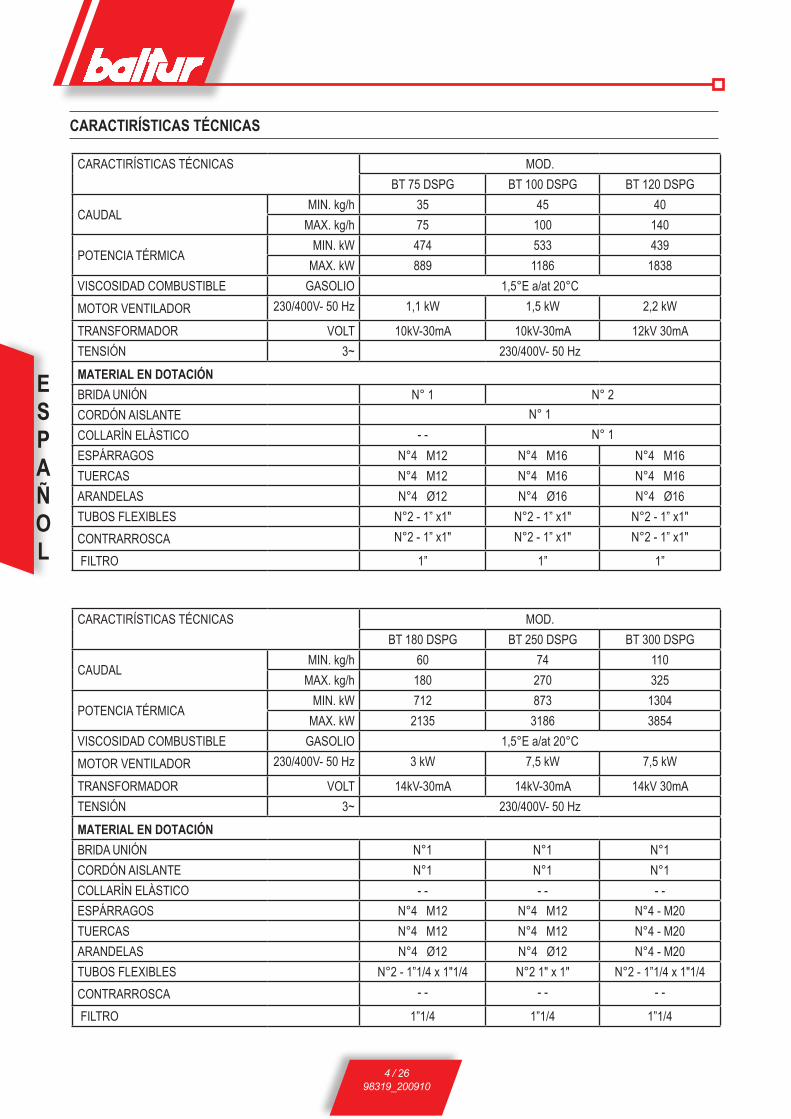
CARACTIRÍSTICAS TÉCNICAS MOD.BT 75 DSPG BT 100 DSPG BT 120 DSPG
CAUDAL MIN. kg/h 35 45 40 MAX. kg/h 75 100 140
POTENCIA TÉRMICA MIN. kW 474 533 439 MAX. kW 889 1186 1838
VISCOSIDAD COMBUSTIBLE GASOLIO 1,5°E a/at 20°C MOTOR VENTILADOR 230/400V- 50 Hz 1,1 kW 1,5 kW 2,2 kW
TRANSFORMADOR VOLT 10kV-30mA 10kV-30mA 12kV 30mATENSIÓN 3~ 230/400V- 50 HzMATERIAL EN DOTACIÓN BRIDA UNIÓN N° 1 N° 2CORDÓN AISLANTE N° 1COLLARìN ELàSTICO - - N° 1ESPÁRRAGOS N°4 M12 N°4 M16 N°4 M16TUERCAS N°4 M12 N°4 M16 N°4 M16ARANDELAS N°4 Ø12 N°4 Ø16 N°4 Ø16TUBOS FLEXIBLES N°2 - 1” x1" N°2 - 1” x1" N°2 - 1” x1"CONTRARROSCA N°2 - 1” x1" N°2 - 1” x1" N°2 - 1” x1"
FILTRO 1” 1” 1”
CARACTIRÍSTICAS TÉCNICAS MOD.BT 180 DSPG BT 250 DSPG BT 300 DSPG
CAUDAL MIN. kg/h 60 74 110 MAX. kg/h 180 270 325
POTENCIA TÉRMICA MIN. kW 712 873 1304 MAX. kW 2135 3186 3854
VISCOSIDAD COMBUSTIBLE GASOLIO 1,5°E a/at 20°C MOTOR VENTILADOR 230/400V- 50 Hz 3 kW 7,5 kW 7,5 kW
TRANSFORMADOR VOLT 14kV-30mA 14kV-30mA 14kV 30mATENSIÓN 3~ 230/400V- 50 HzMATERIAL EN DOTACIÓN BRIDA UNIÓN N°1 N°1 N°1CORDÓN AISLANTE N°1 N°1 N°1COLLARìN ELàSTICO - - - - - - ESPÁRRAGOS N°4 M12 N°4 M12 N°4 - M20TUERCAS N°4 M12 N°4 M12 N°4 - M20ARANDELAS N°4 Ø12 N°4 Ø12 N°4 - M20TUBOS FLEXIBLES N°2 - 1”1/4 x 1"1/4 N°2 1" x 1" N°2 - 1”1/4 x 1"1/4CONTRARROSCA - - - - - -
FILTRO 1”1/4 1”1/4 1”1/4
CARACTIRÍSTICAS TÉCNICAS

ESPAÑOL
5 / 2698319_200910
1 - Bomba2 - Válvula reguladora de presión3 - Modulador4 - Fotorresistencia5 - Transformador de encendido6 - Motor impulsor
7 - Cabeza de combustión8 - Junta aislante9 - Brida de unión al quemador10-Tornillo de regulación del aire a la cabeza de combustión11-Cuadro eléctrico12-Electroimanes
N° 0002270035DOMENSIONES TOTALES
MOD. A A1 A2 B B1 B2 C D E F I I1 L M N MIN MAX Ø ØBT 75 DSPG 595 310 385 510 365 145 1215 130 ÷ 450 205 160 260 260 225 ÷ 300 M12 170BT 100 DSPG 670 330 340 525 365 160 1415 210 ÷ 400 230 195 320 - 276 M16 240BT 120 DSPG 770 390 380 610 450 160 1415 155 ÷ 500 230 195 320 - 276 M16 240BT 180 DSPG 815 390 425 650 450 200 1700 200 ÷ 535 260 220 320 320 280÷370 M12 230BT 250 DSPG 1000 520 480 740 580 160 1700 235 ÷ 560 260 220 320 320 280÷370 M12 230BT 300 DSPG 1000 520 480 800 580 220 1900 245 ÷ 605 360 275 440 440 400÷540 M20 365
BT 100 - 120 DSPG BT 75 - 180 - 250 - 300 DSPG
ESPAÑOL
6 / 2698319_200910
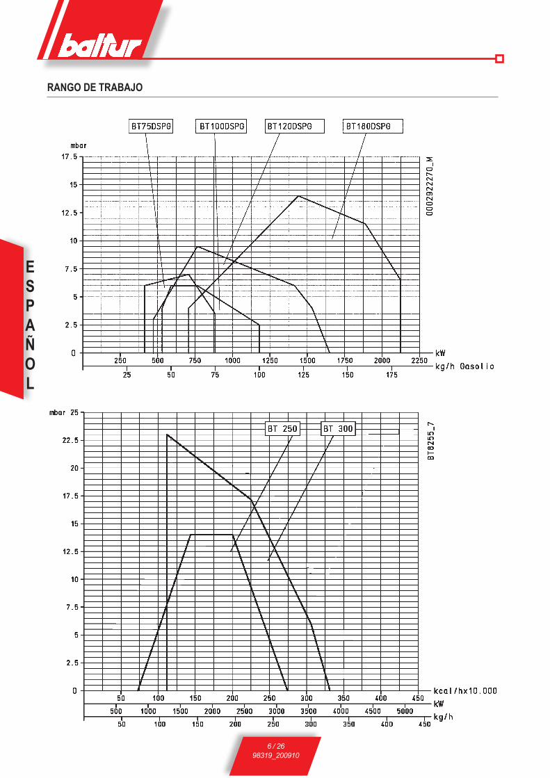
RANGO DE TRABAJO

ESPAÑOL
7 / 2698319_200910
INSTALLACIÒN DEL QUEMADOR A LA CALDERA
Fijacion del quemador a la caldera (Bridas de fijacion de acero) para modelos BT 75 - 100 - 120 DSPG
1 - Placa caldera2 - Brida de material aislante3 - Bridas fijaciòn quemador4 - Collarìn elàstico5 - Prisioniero6 - Tuerca y arandela de bloqueo7 - Tuerca y arandela de fijaciòn de la 1° brida
! Para la fijacion de la brida es muy importante proceder de manera uniforme para que las caras internas sean paralelas entre ellas. Siendo el sistema de sujecion muy eficiente, hay que limitar el apretamiento de las tuercas. Durante esta operacion (apretar las tuercas de bloqueo de las bridas) hay que mantener levantado el cuerpo del quemador de manera que el cabezal de combustion este en posicion horizontal.
INSTALACIÓN DE ALIMENTACIÓN DEL COMBUS-TIBLELa bomba del quemador tiene que recibir el combustible de un cir-cuito de alimentación adecuado, con bomba auxiliar y que puede o no llevar regulador de presión regulable entre 0,2 bar y 1 bar (véase dibujo n° 0002901120).En este caso, el valor de la presión de alimentación del combustible a la bomba del quemador (0,2 ÷ 1 bar) debe ser igual cuando el quemador está apagado y cuando trabaja con el caudal máximo de combustible que requiere la caldera.Normalmente se puede realizar este circuito sin regulador de presión utilizando el esquema de funcionamiento expuesto en el dibujo n° BT 8666/3.Para efectuar el circuito de alimentación siga las instrucciones de nuestros dibujos N° 0002901120 o N° BT 8666/3.Las dimensiones de las tuberías dependen de la longitud de las mismas y del caudal de la bomba que se utiliza.Nuestras disposiciones sólo indican cuanto sea necesario para asegurar un buen funcionamiento.Para conocer las prescripciones que hay que seguir para cumplir las Normas específicas, acuda a los entes nacionales o locales.
CONEXIÓNES ELECTRICASEs aconsejable que todas las conexiones se realicen con cable eléctrico flexible.Las líneas eléctricas tienen que estar alejadas de las partes ca-lientes.Asegúrese de que la línea eléctrica a la que desea conectar el aparato reciba valores de tensión y frecuencia adecuados para el quemador.Cerciórese de que la línea principal, el correspondiente interruptor con fusibles (indispensable) y el posible limitador puedan soportar la corriente máxima que absorbe el quemador. Para más informa-ción, véanse los esquemas eléctricos correspondientes a cada quemador.
Fijacion del quemador a la caldera para modelo BT 180 - 250 - 300 DSPG
N° 00
0293
3340
N° 00
0293
3330
1 Placas de fijación quemadores2 Cordón de material aislante3 Placa de material aislante4 Placa caldera5 Espárragos6 arandelas y tuercas para fijar a la caldera7 Tuercas, tornillos y arandelas para sujetar la placa al soporte
de las boquillas
ESPAÑOL
8 / 2698319_200910
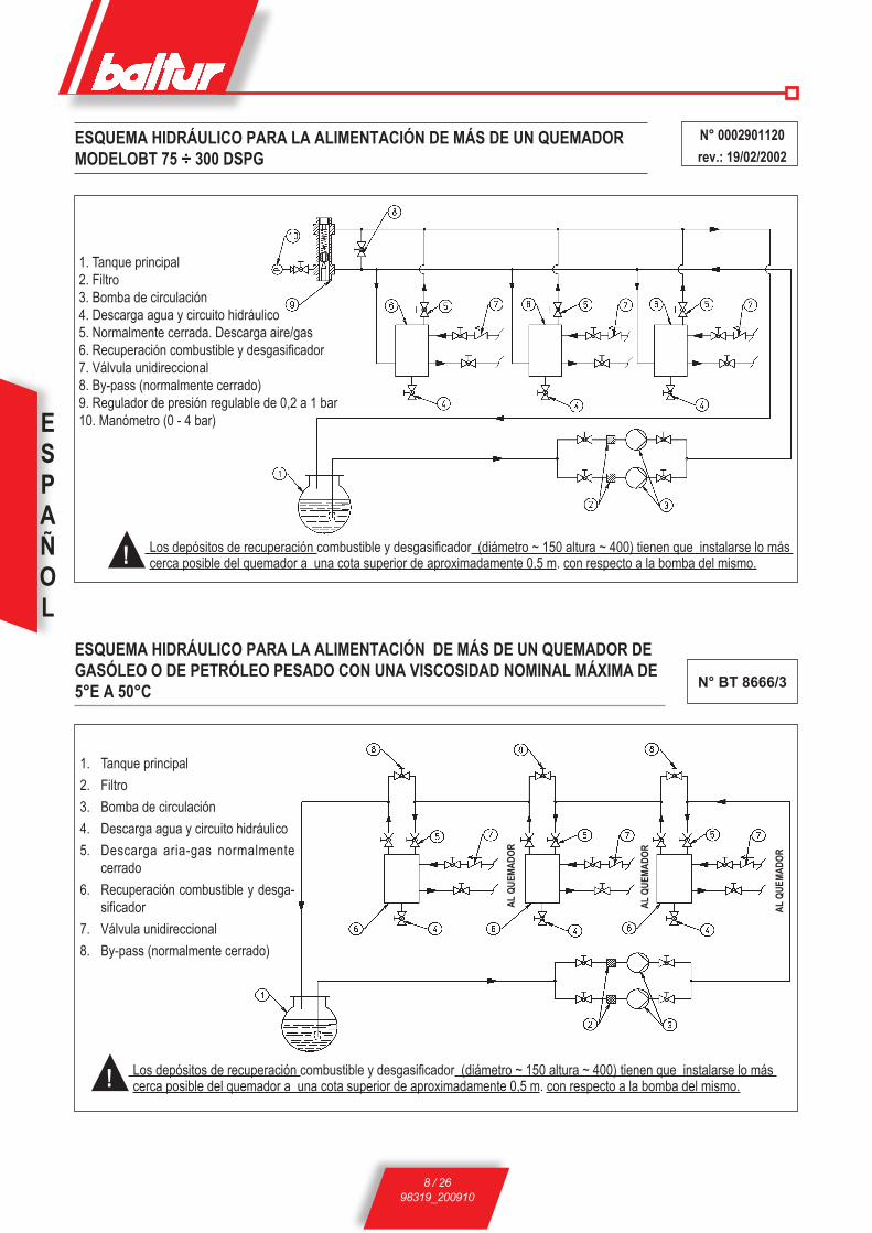
! Los depósitos de recuperación combustible y desgasificador (diámetro ~ 150 altura ~ 400) tienen que instalarse lo más cerca posible del quemador a una cota superior de aproximadamente 0,5 m. con respecto a la bomba del mismo.
1. Tanque principal2. Filtro3. Bomba de circulación4. Descarga agua y circuito hidráulico5. Normalmente cerrada. Descarga aire/gas6. Recuperación combustible y desgasificador7. Válvula unidireccional8. By-pass (normalmente cerrado)9. Regulador de presión regulable de 0,2 a 1 bar10. Manómetro (0 - 4 bar)
AL Q
UEMA
DOR
1. Tanque principal2. Filtro3. Bomba de circulación4. Descarga agua y circuito hidráulico5. Descarga aria-gas normalmente
cerrado6. Recuperación combustible y desga-
sificador7. Válvula unidireccional8. By-pass (normalmente cerrado)
AL Q
UEMA
DOR
AL Q
UEMA
DOR
N° 0002901120rev.: 19/02/2002
N° BT 8666/3
ESQUEMA HIDRÁULICO PARA LA ALIMENTACIÓN DE MÁS DE UN QUEMADOR DE GASÓLEO O DE PETRÓLEO PESADO CON UNA VISCOSIDAD NOMINAL MÁXIMA DE 5°E A 50°C
ESQUEMA HIDRÁULICO PARA LA ALIMENTACIÓN DE MÁS DE UN QUEMADOR MODELOBT 75 ÷ 300 DSPG
! Los depósitos de recuperación combustible y desgasificador (diámetro ~ 150 altura ~ 400) tienen que instalarse lo más cerca posible del quemador a una cota superior de aproximadamente 0,5 m. con respecto a la bomba del mismo.
ESPAÑOL
9 / 2698319_200910
DESCRIPCION DEL FUNCIONAMIENTO CON GA-SOLEO (Véase BT 8714/2)Se llama funcionamiento con dos etapas progresivas puesto que el paso de la primera a la segunda llama (del régimen de mínimo al de máximo establecido) se realiza de manera progresiva tanto en lo que se rifiere a la aportación de aire comburente como al suministro del combustible. La caja de control del quemador (relé cíclico) se conecta a través del interruptor del cuadro (I).La caja de control con relé cíclico ejecuta el programa de encendido y para ello pone en marcha el motor del ventilador, y por consiguiente la bomba, para realizar las fases de prebarrido y precirculación del gasóleo. El gasóleo sale de la bomba y llega al grupo pulverizador; el combustible circula dentro del grupo pulverizador sin poder salir puesto que los pasos hacia la boquilla (ida) y desde la boquilla (re-torno) están cerrados. Este cierre se consigue mediante las “agujas de cierre” colocadas en los extremos de las varillas. Una serie de muelles robustos colocados en el extremo opuesto de las varillas se encargan de apretar las agujas contra los emplazamientos. El gasóleo circula, sale del retorno del grupo pulverizador y llega al regulador de presión de retorno; lo atraviesa, llega al retorno de la bomba y desde la bomba se descarga en el retorno. La circulación del gasóleo que acabamos de mencionar se efectúa a un valor de presión un poco más alto (algunos bares de más) con respecto a la presión mínima a la que está regulado el regulador de presión de retorno (10÷12 bares). Esta fase de prebarrido y precirculación del gasóleo no dura 22,5 segundos como preve la caja de control, puesto que dicha fase se lleva a cabo con la clapeta del aire en la posición abierta. Por lo tanto, para calcular la duración del preba-rrido y precirculación debemos sumar los tiempos de las siguientes operaciones:Carrera de abertura del motor de modulación (45 segundos) +Tiempo de prebarrido previsto por la caja de control (22,5 segun-dos) +Carrera de cierre del motor de modulación hasta la posición de aire de encendido (aprox. 40 segundos).Por lo tanto, la duración total del prebarrido y precirculación del gasóleo es de unos 107 segundos.A continuación, la caja de control sigue con el programa de encen-dido y conecta el transformador de encendido, que alimenta los electrodos con alta tensión. La alta tensión entre los electrodos produce la descarga eléctrica (chispa) que permite que se encien-da la mezcla de combustible y aire. Después de 2,5 segundos del inicio de la chispa de encendido la caja de control lleva tensión al electroimán; éste, mediante oportunos mecanismos de levas hace retroceder las dos varillas de corte del flujo de gasóleo hacia la boquilla (ida y retorno). El retroceso de las varillas también comporta el cierre del paso interno (by-pass) hacia el grupo pulverizador y, por consiguiente, la presión en la bomba vuelve al valor normal de 20÷22 bares. El retroceso de las dos varillas de los emplazamientos de cierre permite que el combustible entre en la boquilla a la presión
CAJA DE CONTROL Y PROGRAMADOR
LAL 1.25 Relé cíclico
TIEMPO DE SEGURI-DAD EN SEGUNDOS
5
TIEMPO DE PREVENTILA-CIÓN Y PRECIRCULACIÓN
DEL COMBUSTIBLE EN SEGUNDOS
22,5
PREENCENDIDO EN SEGUNDOS
2,5
POST-ENCENDIDO EN SEGUNDOS
5
TIEMPO ENTRE LA 1ª LLA-MA Y INICIO DE LA MODU-LACIÓN EN SEGUNDOS
15
Características de la caja de control
regulada en la bomba (20÷22 bares) y salga de la boquilla pulveriza-do de forma correcta. La presión de retorno determina el consumo en la cámara de combustión y está regulada por el regulador de presión de retorno. Para el caudal de encendido (consumo mínimo) este valor es de unos 10÷12 bares. El gasóleo pulverizado que sale de la boquilla se mezcla con el aire que suministra el ventilador y se enciende con la chispa que se produce entre los electrodos. La fotorresistencia registra la presencia de la llama.El programador prosigue y al cabo de 5 segundos supera la posición de bloqueo, desconecta el encendido y a continuación conecta el circuito de modulación. El motor de modulación controla a la vez el aumento del caudal del combustible y del aire de combustión. El disco con perfil variable determina el aumento del caudal del gasóleo. Dicho disco, cuando gira realiza una mayor compresión del muelle del regulador de la presión de retorno y, por lo tanto, aumenta la presión; así pues, al aumento de presión de retorno corresponde un aumento del caudal del combustible. Al aumento del caudal del combustible tiene que corresponder un aumento del aire de com-bustión en la medida adecuada (en la cantidad adecuada). Esta situación se produce durante la primera regulación, ajustando los tornillos que varían el perfil del disco de control de la regulación del aire de combustión. El consumo del combustible y al mismo tiempo del aire comburente aumenta hasta llegar al valor máximo (presión en el regulador de la presión de retorno equivalente a unos 18÷20 bares, si la presión en la bomba es de 20÷22 bares). El consumo de combustible y aire comburente permanece en el valor máximo hasta que la temperatura de la caldera (o presión, si se trata de caldera de vapor) se aproxima al valor regulado en el termóstato (o presóstato) de la 2a etapa; ello conlleva que el servomotor de regulación del consumo (combustible/aire) se mueva en el sentido contrario al movimiento precedente, reduciendo gradualmente el consumo del combustible y el aire comburente hasta alcanzar el valor mínimo. Si incluso con el consumo mínimo de combustible y aire comburente también se alcanza la temperatura máxima (presión, en el caso de calderas de vapor), el termóstato (o presóstato) interviene cuando se llega al valor al que se ha regulado y determina la parada completa del quemador. Cuando la temperatura (o presión, si se trata de cal-dera de vapor) ha disminuido por debajo del valor al que interviene el dispositivo de parada, el quemador vuelve a ponerse en marcha como hemos descrito con anterioridad. Cuando el quemador trabaja con normalidad el termóstato (o presóstato) de la 2a etapa percibe las variaciones de carga de la caldera y automáticamente solicita que el servomotor de regulación del consumo (combustible/aire) ajuste del consumo de gasóleo y aire comburente. Con esta operación, el sistema de regulación del consumo (combustible/aire) alcanza una posición equilibrada con un consumo de combustible y aire que equivale a la cantidad de calor que solicita la caldera.
! Tenga en cuenta que el campo de variación del caudal obtenido con una buena combustión es indicativamente de 1 a 1/3 respecto al caudal máximo indicado en la placa.

ESPAÑOL
10 / 2698319_200910
ESQUEMA PARA QUEMADORES MODULANTES DE GASÓLEO (MAGNETO - BO-QUILLA SIN AGUJA)
1 - FILTRO 2 - BOMBA QUEMADOR3 - MANÒMETRO (0 - 40 bar)4 - GRUPO PULVERIZADOR5 - BOQUILLA DE RETORNO SIN AGUJA6 - VARILLAS CON AGUJAS DE CIERRE7 - ORIFICÍOS DE BY-PASS8 - MULLES DE CIERRE9 - ELECTROIMàN DE ABERTURA10 - REGULADOR DE PRESIÒNDE RETORNO MIN = 10÷12 bar
MAX = 18÷20 bar
11 - SERVOMOTOR DE MODULACIÓN12 - DISCO MANDO VARIACIÓN CAUDAL COMBUSTIBLE - AIRE13 - CLAPETAS REGULACIÓN AIRE14 - TUBOS FLEXIBLES
COLLEGAMIENTO AL CIR-CUITO DE ALIMENTACIÓN (VÉASE 0002901120) PARA UNO O MAS QUEMADORES
N° BT 8714/2rev.: 19/02/2002

ESPAÑOL
11 / 2698319_200910
BOQUILLA (CB) CHARLES BERGONZO DESMONTADA (SIN AGUJA)
Bomba BALTUR MODELO BT.....
N° B
T 93
53/1
Datos de identificación de la tobera:Suministro en Kg/h Ángulo de rociado (30°-45°-60°-80°) Relación de suministro (1/3 = B3 – 1/5 = B5) Anillo de capacidad en Viton
(resistente al aceite y a la alta temperatura) Cámara de turbulencia
Retorno del combustibleOrificio de salida del combustible
Orificio de retorno del combustible
! Para que la tobera funcione correctamente, es indispensable que el «retorno» de la misma no esté nunca completamente cerrado. Esta condición se deberá verificar cuando el quemador se encienda por primera vez. En la práctica, cuando la tobera funciona con el suministro máximo seleccionado, la diferencia de presión entre el “envío” a la tobera (presión de la bomba) y el “retorno” a la tobera (presión en el regulador de presión de retorno) es, como mínimo de 2 ÷ 3 bar.
Ejemplo Presión de la bomba: 20 bar Presión de la bomba: 22 bar Presión de retorno: 20 - 2 = 18 bar Presión de retorno: 22 - 3 = 19 bar Presión de retorno: 20 - 3 = 17 bar Presión de retorno: 22 - 2 = 20 bar
Entrada de combustible
N° 00
0290
0580
Aspiración Sujeción vacuómetro 1/4”Retorno
Placa de la bomba
Envío (tobera)
Sujeción manómetro 1/4”
Posición del elemento calentador
Regulación de la presión de la bomba (20 ÷ 22 bar)
Aspiración Sujeción vacuómetro 1/4”Retorno
Envío (tobera)
Sujeción manómetro 1/4”
Posición del elemento calentador
Regulación de la presión de la bomba (20 ÷ 22 bar)
Placa de la bomba
ESPAÑOL
12 / 2698319_200910
ENCENDIDO Y REGULACION CON GASOLEO1) Compruebe que las características de la boquilla (consumo y
ángulo de pulverización) sean adecuadas para la cámara de combustión (Véase BT 9353/1). En caso contrario, substituya la boquilla por otra que sea adecuada.
2) Compruebe que el tanque contenga combustible y que, al menos a simple vista, éste sea adecuado para el quemador.
3) Compruebe que haya agua en la caldera y que las válvulas de la instalación estén abiertas.
4) Asegúrese con certeza que la evacuación de los pro-ductos de combustión pueda efectuarse sin obstruccio nes (las clapetas del aire y la chimenea tienen que estar abiertas)
5) Compruebe que la tensión de la línea eléctrica a la que quiere conectar el quemador corresponda a la tension que solicita el fabricante y que las conexiones eléctricas del motor estén predispuestas para el valor de tensión disponible. Asimismo, compruebe que todas las conexiones eléctricas se realicen correctamente siguiendo nuestro esquema eléctrico.
6) Asegúrese de que la cabeza de combustión sea suficientemente larga para que pueda entrar en la cámara de combustión en la medida que indica el fabricante de la caldera. Compruebe que el dispositivo de regulación del aire en la cabeza de combustión se encuentre en la posición que se considera adecuada para el consumo de combustible solicitado (en caso de que el consumo de combustible sea relativamente reducido, el paso de aire entre el disco y la cabeza debe estar bastante cerrado; si, por el con-trario, la boquilla tiene un consumo más bien elevado, el paso de aire entre el disco y la cabeza deberá estar bastante abierto). Véase el capítulo «Regulación de la cabeza de combustión».
7) Quite la tapa de protección del disco giratorio, acoplado en el motor de modulación, en el que están enrosca- dos los tornillos de regulación para el control del combustible y el aire de combustión correspondiente.
8) Regule los dos interruptores de modulación en la posición «MIN» (mínimo) y «MAN» (manual).
9) Ponga en marcha el circuito auxiliar de alimentación del com-bustible, compruebe la eficacia del mismo y si dispone de un regulador de presión, regule la presión a casi 1 bar.
10) Quite el tapón de la bomba que se encuentra en el em-plazamiento de conexión del vacuómetro y a continua- ción abra ligeramente la válvula colocada en la tube-ría de llegada del combustible. Espere hasta que el combustible salga por el orificio sin presencia de burbujas de aire y después vuelva a cerrar la válvula.
11) Aplique un manómetro (calibre aprox. 3 bares) en el emplaza miento de conexión del vacuómetro previsto enla bomba para poder controlar el valor de la presión del combustible cuando llega a la bomba del quemador. Aplique un manómetro (calibre aprox. 30 bares) en el emplazamiento de conexión manómetro previsto en la bomba para poder controlar la presión de trabajo de la misma. Aplique un manómetro (calibre aprox. 30 bares)
en la correspondiente conexión del regulador de la presión de retorno de la primera llama (véase BT 8714/1) para controlar la presión de retorno.
12) Abra todas las válvulas y otros posibles dispositivos de corte colocados en las tuberías del gasóleo.
13) Coloque el interruptor, situado en el cuadro de mando, en la posición «0» (abierto) y conecte la corriente a la línea eléctrica en la que hemos conectado el quemador. Apriete manualmente el telerruptor para comprobar que el motor del ventilador y de la bomba gira en el sentido correcto; si fuera necesario, cambie de lugar dos cables de la línea principal para invertir el sentido de rotación.
14) P o n g a l a b o m b a d e l q u e m a d o r e n f u n c i o n a -miento; para ello, apriete manualmente el telerruptor correspondiente hasta que el manómetro que detec-ta la presión de trabajo de la bomba indique una ligera presión. La presencia de una presión baja en el circuito confirma que se ha realizado el llenado.
15) Conecte el interruptor del cuadro de mando para dar corriente a la caja de control. Si los termóstatos (seguridad y caldera) están cerrados, se activa el pro-gramador de la caja de control , que conectará los dispositivos del quemador según el programa prestablecido. El aparato se enciende tal como explicamos en el capítulo «Descripción del funcionamiento».
16) Cuando el quemador esté funcionando al «mínimo», se regula el aire a la cantidad necesaria para garantizar una buena combustión. Para ello, desenrosque o enrosque un poco más los tornillos de regulación que se encuentran en relación con el punto de contacto con la leva que transmite el movimiento a la clapeta de regulación del aire de combustión. Es preferible que la cantidad de aire para el «mínimo» sea ligeramente escasa para asegurar un encendido perfecto incluso en los casos más difíciles.
17) Tras haber regulado el aire para el “mínimo”, conecte los interruptores de la modulación en posición «MAN» (manual) y «MAX» (máximo).
18) El motor de modulación se pone en movimiento; espere hasta que el disco (al que hemos colocado los tornillos de regula-ción) haya recorrido un ángulo de unos 12° (correspondiente al espacio que ocupan 3 tornillos) y a continuación, pare la modulación y vuelva a colocar el interruptor en la posición «0». Realice un control visual de la llama y si fuera necesario, regule el aire de combustión siguiendo las indicaciones del punto 16. Después, controle la combustión mediante los instrumentos correspondientes y en caso oportuno modifique la regulación efectuada anteriormente con control visual.Repita la operación que acabamos de describir procediendo de manera progresiva (avance el disco unos 12° cada vez) y modifique la relación combustible/aire cada vez que fuera necesario durante toda la carrera de la modulación. Asegúrese de que la progresión en el suministro del combustible se realiza de manera gradual y que el consumo máximo se produzca al final de la carrera de modulación. Este requisito es necesario para efectuar una buena gradualidad en el funcionamiento de la modulación. Si fuera necesario, modifique la posición de los tornillos que controlan el combustible para obtener cuanto acabamos de exponer.
ESPAÑOL
13 / 2698319_200910
Le recordamos que el consumo máximo se obtiene cuando la presión de retorno es de unos 2÷3 bares inferior a la presión de impulsión (normalmente 20÷22 bares). Para una correcta rela-ción aire/combustible es preciso obtener un valor de anhídrido carbónico (CO2), que aumenta si aumenta el consumo (a título indicativo, al menos 10% en el consumo mínimo hasta el valor óptimo del 13% de CO2 en el consumo máximo). Es desaconse-jable superar el valor del 13% de CO2 para evitar que el exceso de aire sea más bien limitado, lo que podría causar un aumento considerable de la opacidad del humo por causas inevitables (variación de la presión atmosférica, presencia de pequeños depósitos de polvo en los conductos de aire del ventilador, etc.) La opacidad de humos que obtenemos está muy relacionada con el tipo de combustible utilizado (las últimas disposiciones al respecto indican que el valor máximo en la escala de Bacharach es el n° 2). Aconsejamos mantener la opacidad de los humos en un valor inferior al n° 2 de la escala de Bacharach siempre que sea posible aunque, por consiguiente, el valor del CO2 podría ser algo inferior. Si disponemos de un valor menor de opacidad de humos, la caldera se ensucia menos y, por lo tanto, el rendimiento medio de la caldera será más alto aunque el CO2 sea ligeramente inferior. Le recordamos que para efectuar una buena regulación es necesario que la temperatura del agua en la instalación esté en estado de régimen (a la temperatura de regulación) y que el quemador lleve un mínimo de quince minutos funcionando. Si no dispone de los instrumentos adecuados, puede basarse en el color de la llama. Aconsejamos efectúe la regulación de manera que la llama que obtenga sea de color naranja claro; evite la llama roja con presencia de humo y la llama blanca con demasiado exceso de aire. Tras haber controlado que la regulación (aire/combustible) sea correcta, apriete los tornillos de bloqueo de los tornillos de regulación.
19) A continuación controle que el funcionamiento automático de la modulación sea correcto; ponga el interruptor AUT - 0 - MAN en la posición «AUT» y el interruptor MIN - 0 - MAx en la posición «0». De este modo, si disponemos de un quemador en versión modulante (M), la modulación se conecta únicamente con el accionamiento automático de la sonda de caldera; si se trata de un quemador con dos etapas progresivas (BT…DSPG), la modulación se conecta por el accionamiento del termóstato o presóstato de la 2a etapa.
20) Compruebe la eficacia del detector de llama (fotorresistencia).La fotorresistencia es el dispositivo de control de llama y, por lo tanto, debe ser capaz de intervenir si la llama se apaga durante el funcionamiento (realice este control cuando haya pasado al menos un minuto desde el encendido). El quemador debe bloquearse y permanecer en esta posición cuando no aparece la llama durante la fase de encendido y durante el tiempo establecido por la caja de control. El bloqueo conlleva el corte inmediato del suministro de combustible y, por lo tanto, el quemador se para y se enciende el indicador de bloqueo.Para controlar la eficacia de la fotorresistencia y del bloqueo, proceda del modo siguiente:
a) Ponga el quemador en funcionamiento.b) Cuando haya pasado al menos un minutodesde el momento del
encendido saque la fotorresistencia de su posición y simule la falta de llama oscureciendo la fotorresistencia (cierre la ventana que se encuentra en el soporte de la fotorresistencia con un trapo). De este modo se apaga la llama del quemador.
c) Si mantenemos la fotorresistencia en la oscuridad, el quemador se vuelve a encender pero lafotorresistencia no ve la luz y, tras
el tiempo establecido por el programa de la caja de control, se bloquea. La caja de control sólo se puede desbloquear manual-mente apretando el botón correspondiente (desbloqueo). La prueba de la eficacia del bloqueo debe realizarse como mínimo dos veces.
21) Controle la eficacia de los termóstatos o presóstatos de la cal-dera (la intervención de los mismos debe parar el quemador).
REGULACIÓN DE LA CABEZA DE COMBUSTIONEl quemador dispone de una cabeza de combustión que puede regularse hacia adelante o hacia atrás, para cerrar o abrir el paso del aire entre el disco y la cabeza. De este modo, si reducimos el paso de aire obtenemos una presión elevada en la entrada del disco, incluso para los caudales bajos. Por consiguiente, la elevada velocidad y turbulencia del aire permiten que el aire penetre mejor en el combustible y, obtenemos una excelente mezcla y estabilidad de llama. Puede que sea imprescindible disponer de una presión elevada de aire en la entrada del disco para evitar pulsaciones de llama; este requisito es prácticamente indispensable cuando el quemador trabaja con hogar presurizado y/o alta carga térmica.A partir de lo que acabamos de explicar se deduce que debemos regular el dispositivo que cierra el paso de aire a la cabeza de combustión a una posición que nos permita obtener siempre un valor de presión del aire bastante alto detrás del disco.Le aconsejamos que regule el cierre del paso de aire a la cabeza a una posición que requiera una ligera abertura de la clapeta del aire que regula el flujo en la aspiración del ventilador del quemador. Evidentemente, este requisito debe cumplirse cuando el quemador trabaja con el caudal máximo deseado. En la práctica, se debe empezar regulando el dispositivo que cierra el paso de aire a la cabeza de combustión a una posición intermedia, y después se enciende el quemador para una regulación orientativa, tal y como hemos expuesto anteriormente.Cuando se ha alcanzado el consumo máximo deseado se corrige la posición del dispositivo que cierra el paso del aire a la cabeza de combustión. Para ello, desplace el dispositivo hacia adelante o hacia atrás, con la clapeta de regulación del aire en aspiración bastante abierta, para obtener un flujo de aire adecuado al consumo.Si se desplaza la cabeza de combustión hacia adelante (reducción del paso de aire entre la cabeza y el disco), evite el cierre total.Cuando realice la regulación de la cabeza de combustión, asegú-rese de que la cabeza quede perfectamente centrada respecto al disco. Cabe destacar que si el centrado respecto al disco no es perfecto, la combustión podría ser mala y la cabeza de combustión se calentaría en exceso, provocando un deterioro rápido.Para hacer la comprobación, observe a través de la mirilla colocada en la parte posterior del quemador; después, apriete fuertemente los tornillos que bloquean la posición del dispositivo de regulación del aire a la cabeza de combustión.
! Compruebe que el encendido se produzca correcta-mente puesto que, si hemos desplazado el regulador hacia adelante, la velocidad del aire en salida podría ser sea tan elevada que haría difícil el encendido. Si se produjera esta situación, es necesario desplazar el regulador hacia atrás por grados hasta llegar a una posición en la que el encendido se realice correcta-mente; cuando hayamos encontrado esta posición la consideraremos la definitiva. Le recordamos que para la 1a llama es preferible limitar la cantidad del aire al mínimo indispensable para obtener un encendido seguro, incluso en los casos más difíciles.

ESPAÑOL
14 / 2698319_200910
N° B
T 86
08/1
ESQUEMA DE PRINCIPIO REGULACIÓN DEL AIRE
ESQUEMA INDICATIVO DISPOSICIÓN DISCO - BOQUILLAS - ELECTRODOS
N° 00
0293
1451

ESPAÑOL
15 / 2698319_200910
Indice de referencia
Eje de levas
Levas regulables
Apertura máxima aire inal de carrera
Cierr total aire(quemador detenido)
Apertura airede encendido
B = Palanca de inserción y exclusión unión motor - eje de levas Posición 1 = excluido Posición 2 = activado
VISTA DEL MOTOR SQM 10 Y SQM 20 DE MANDO MODULACIÓN PARA REGULACIÓN LEVAS
N° BT 8562/2
Para modificar la regulación de las 3 levas utilizadas, se opera con los respectivos anillos ( A - Z - M ) de color rojo. Empujando con suficiente fuerza en el sentido deseado, cada anillo (rojo) puede girar respecto a la escala de referencia.El indice del anillo rojo indica en la respectiva escala de referencia el ángulo de rotación predispuesto para cada leva.
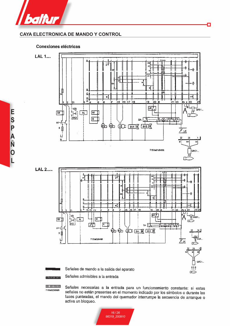
ESPAÑOL
16 / 2698319_200910
Caya eleCTroNiCa de maNdo y CoNTrol

ESPAÑOL
17 / 2698319_200910
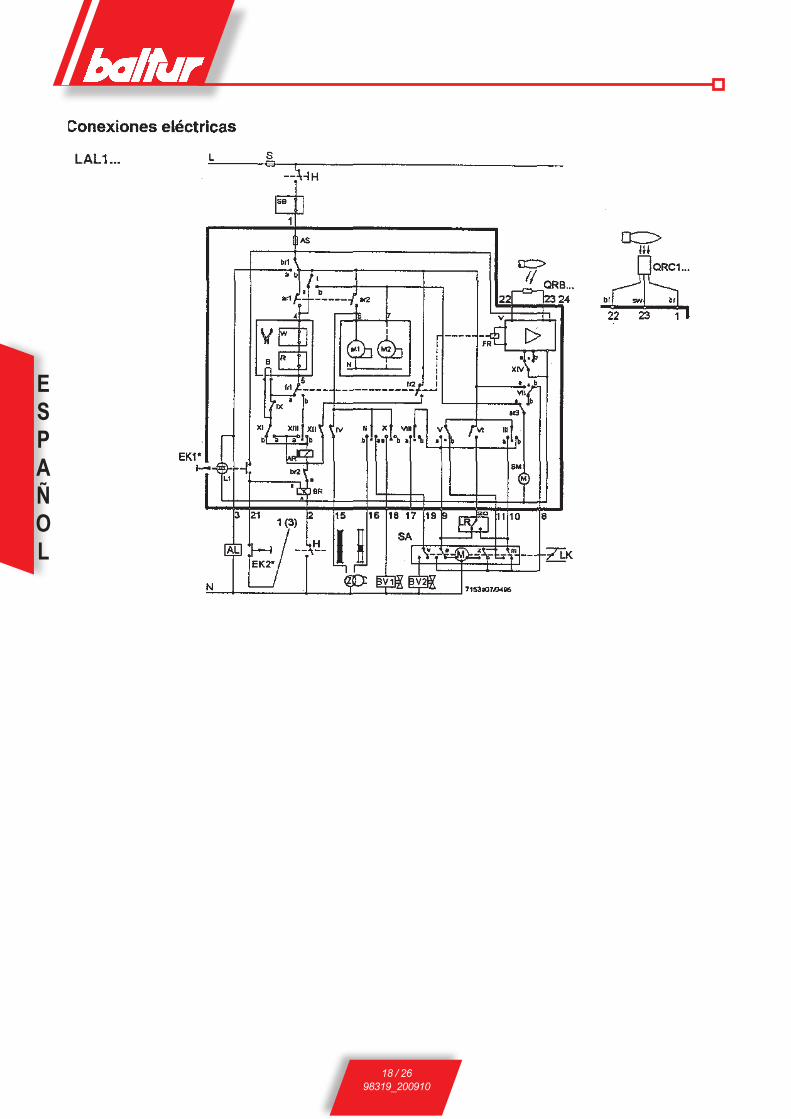
ESPAÑOL
18 / 2698319_200910
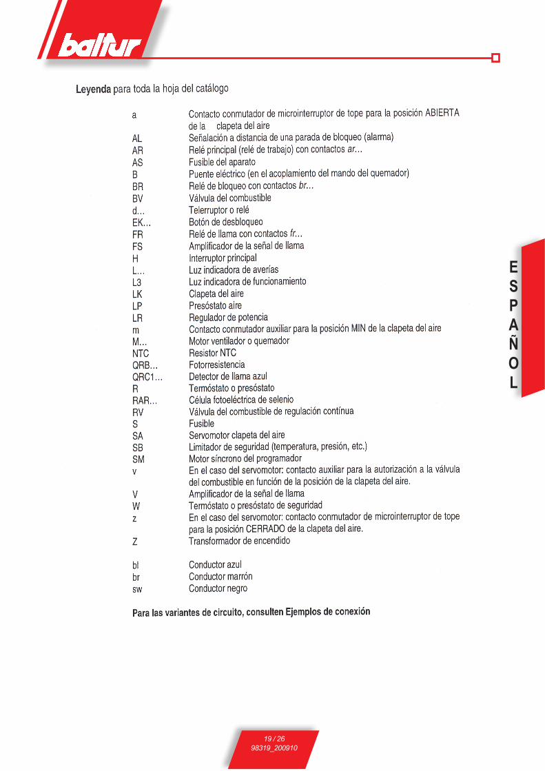
ESPAÑOL
19 / 2698319_200910
ESPAÑOL
20 / 2698319_200910
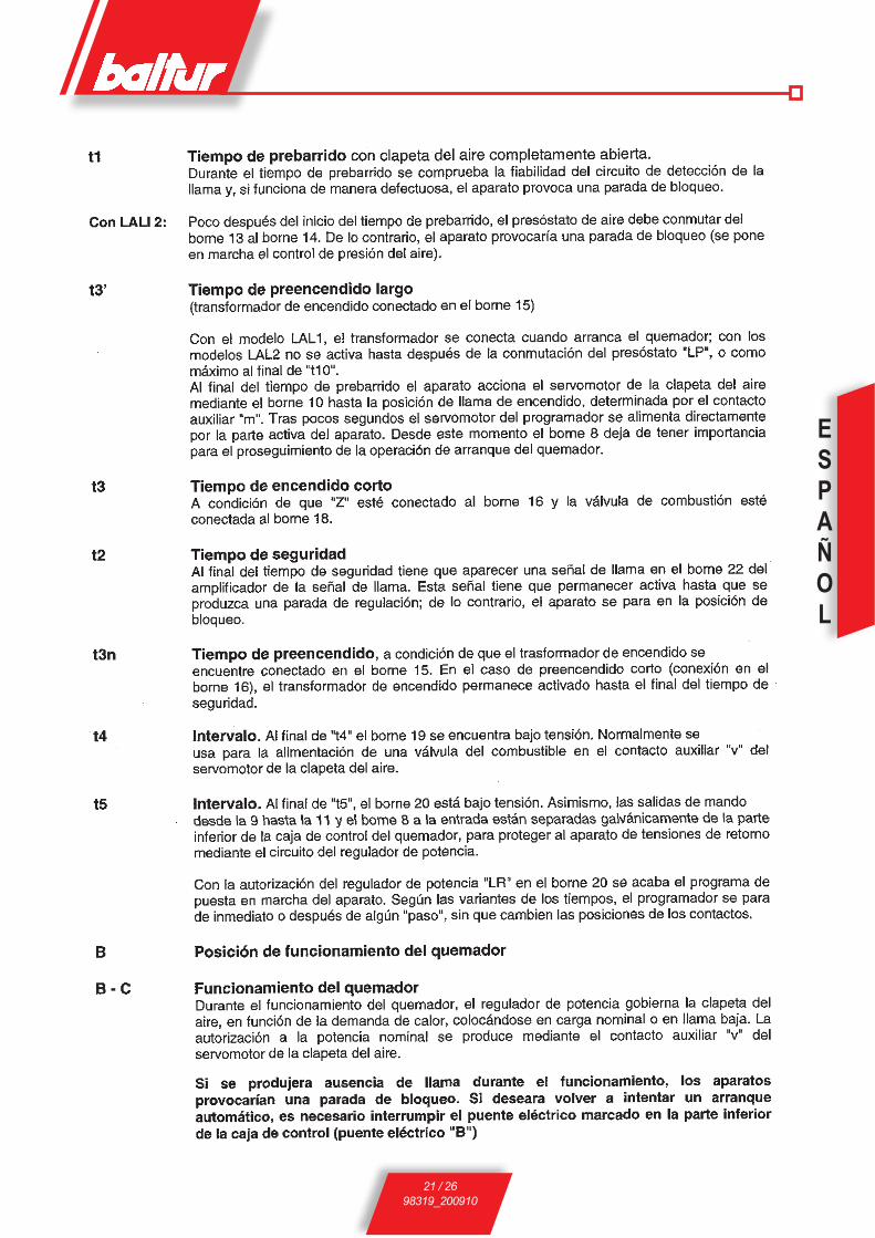
ESPAÑOL
21 / 2698319_200910

ESPAÑOL
22 / 2698319_200910

ESPAÑOL
23 / 2698319_200910
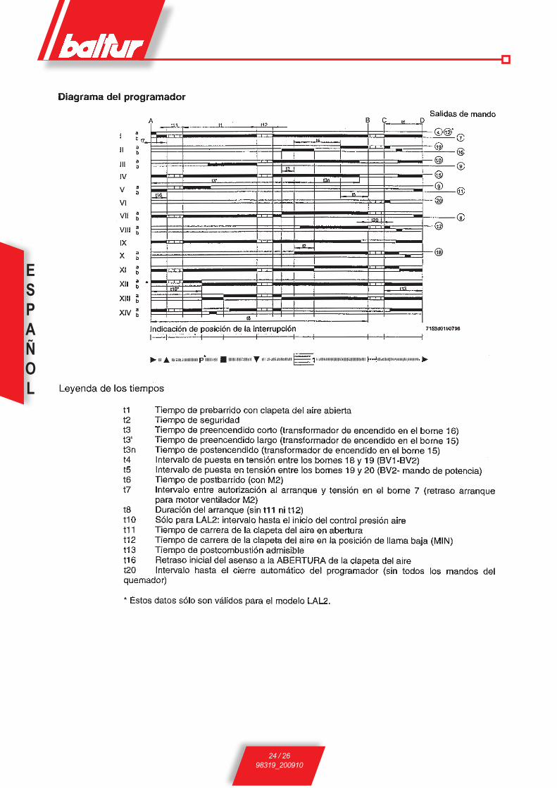
ESPAÑOL
24 / 2698319_200910

ESPAÑOL
25 / 2698319_200910
1 mbar = 10 mmC.A. 100 Pa1 kW = 860 kcal
Densidad del gasóleo .................................. = 0,820 / 0,830 PCI = 10150
Densidad del especial .................................. = 0,900 PCI = 9920
Densidad del doméstico (3,5°E) ................... = 0,940 PCI = 9700
Densidad del denso (7,9°E) ........................ = 0,970 / 0,980 PCI = 9650
PCI = Poder calorifico inferior
TABLA CAUDAL BOQUILLAS PARA GASÓLEO
Boquilla Presión bomba Boquilla7 8 9 10 11 12 13 14 15 16 17 18 19 20 21
G.P.H. Caudal a la salida de la boquilla G.P.H.0,40 1,27 1,36 1,44 1,52 1,59 1,67 1,73 1,80 1,86 1,92 1,98 2,04 2,10 2,15 2,20 0,400,50 1,59 1,70 1,80 1,90 1,99 2,08 2,17 2,25 2,33 2,40 2,48 2,55 2,62 2,69 2,75 0,500,60 1,91 2,04 2,16 2,28 2,39 2,50 2,60 2,70 2,79 2,88 2,97 3,06 3,14 3,22 3,30 0,600,65 2,07 2,21 2,34 2,47 2,59 2,71 2,82 2,92 3,03 3,12 3,22 3,31 3,41 3,49 3,58 0,650,75 2,38 2,55 2,70 2,85 2,99 3,12 3,25 3,37 3,49 3,61 3,72 3,82 3,93 4,03 4,13 0,750,85 2,70 2,89 3,06 3,23 3,39 3,54 3,68 3,82 3,96 4,09 4,21 4,33 4,45 4,57 4,68 0,851,00 3,18 3,40 3,61 3,80 3,99 4,16 4,33 4,50 4,65 4,81 4,96 5,10 5,24 5,37 5,51 1,001,10 3,50 3,74 3,97 4,18 4,38 4,58 4,77 4,95 5,12 5,29 5,45 5,61 5,76 5,91 6,06 1,101,20 3,82 4,08 4,33 4,56 4,78 5,00 5,20 5,40 5,59 5,77 5,95 6,12 6,29 6,45 6,61 1,201,25 3,97 4,25 4,50 4,75 5,00 5,20 5,40 5,60 5,80 6,00 6,20 6,35 6,55 6,70 6,85 1,251,35 4,29 4,59 4,87 5,13 5,38 5,62 5,85 6,07 6,28 6,49 6,69 6,88 7,07 7,26 7,44 1,351,50 4,77 5,10 5,41 5,70 5,90 6,24 6,50 6,75 6,98 7,21 7,43 7,65 7,86 8,06 8,26 1,501,65 5,25 5,61 5,95 6,27 6,58 6,87 7,15 7,42 7,68 7,93 8,18 8,41 8,64 8,87 9,09 1,651,75 5,56 5,95 6,31 6,65 6,98 7,29 7,58 7,87 8,15 8,41 8,67 8,92 9,17 9,41 9,64 1,752,00 6,30 6,80 7,21 7,60 7,97 8,33 8,67 8,99 9,31 9,61 9,91 10,20 10,48 10,75 11,01 2,002,25 7,15 7,65 8,15 8,55 8,97 9,37 9,75 10,12 10,47 10,85 11,15 11,47 11,79 12,09 12,39 2,252,50 7,95 8,50 9,01 9,50 9,97 10,41 10,83 11,24 11,64 12,02 12,39 12,75 13,10 13,44 13,77 2,503,00 9,54 10,20 10,82 11,40 11,96 12,49 13,00 13,49 13,96 14,02 14,87 15,30 15,72 16,12 16,52 3,003,50 11,13 11,90 12,62 13,30 13,95 14,57 15,17 15,74 16,29 16,83 17,34 17,85 18,34 18,81 19,28 3,504,00 12,72 13,60 14,42 15,20 15,94 16,65 17,33 17,99 18,62 19,23 19,82 20,40 20,95 21,50 22,03 4,004,50 14,31 15,30 16,22 17,10 17,94 18,73 19,50 20,24 20,95 21,63 22,30 22,95 23,57 24,19 24,78 4,505,00 15,90 17,00 18,03 19,00 19,93 20,82 21,67 22,48 23,27 24,04 24,78 25,49 26,19 26,87 27,54 5,005,50 17,49 18,70 19,83 20,90 21,92 22,90 23,83 24,73 25,60 26,44 27,25 28,04 28,81 29,56 30,29 5,506,00 19,00 20,40 21,63 22,80 23,92 24,98 26,00 26,98 27,93 28,84 29,73 30,59 31,43 32,25 33,04 6,006,50 20,67 22,10 23,44 23,70 25,91 27,06 28,17 29,23 30,26 31,25 32,21 33,14 34,05 34,94 35,80 6,507,00 22,26 23,79 25,24 26,60 27,90 29,14 30,33 31,48 32,58 33,65 34,69 35,69 36,67 37,62 38,55 7,007,50 23,85 25,49 27,04 28,50 29,90 31,22 32,50 33,73 34,91 36,05 37,16 38,24 39,29 40,31 41,31 7,508,30 26,39 28,21 29,93 31,54 33,08 34,55 35,97 37,32 38,63 39,90 41,13 42,32 43,48 44,61 45,71 8,309,50 30,21 32,29 34,25 36,10 37,87 39,55 41,17 42,72 44,22 45,67 47,07 48,44 49,77 51,06 52,32 9,5010,50 33,39 35,69 37,86 40,06 41,73 43,74 45,41 47,20 48,90 50,50 52,00 53,50 55,00 56,40 57,80 10,5012,00 38,20 40,80 43,30 45,60 47,80 50,00 52,00 54,00 55,90 57,70 59,50 61,20 62,90 64,50 66,10 12,0013,80 43,90 46,90 49,80 52,40 55,00 57,50 59,80 62,10 64,20 66,30 68,40 70,40 72,30 74,30 76,00 13,8015,30 48,60 52,00 55,20 58,10 61,00 63,70 66,30 68,80 71,10 73,60 75,80 78,00 80,20 82,20 84,30 15,3017,50 55,60 59,50 63,10 66,50 69,80 72,90 75,80 78,70 81,50 84,10 86,70 89,20 91,70 94,10 96,40 17,5019,50 62,00 66,30 70,30 74,10 77,70 81,20 84,50 87,70 90,80 93,70 96,60 99,40 102,20 104,80 107,40 19,5021,50 68,40 73,10 77,50 81,70 85,70 89,50 93,20 96,70 100,10 103,40 106,50 109,60 112,60 115,60 118,40 21,5024,00 76,30 81,60 86,50 91,20 95,70 99,90 104,00 107,90 111,70 115,40 118,90 122,40 125,70 129,00 132,20 24,0028,00 89,00 95,20 101,00 106,40 111,60 116,60 121,30 125,90 130,30 134,60 138,70 142,80 146,70 150,50 154,20 28,0030,00 95,40 102,00 108,20 114,00 119,60 124,90 130,00 134,90 139,60 144,20 148,70 153,00 157,20 161,20 165,20 30,00

ESPAÑOL
26 / 2698319_200910
РУССКИЙ
1 / 3098319_200910
Вице-президентиУполномоченныйадминистратор:
ДокторРиккардоФава
ДекларациясоответствияЗаявляемподнашуответственность,чтоизделиясмаркой"ЕС"Серии:Sparkgas…; BTG…; BGN…; minicomist…; Comist…; riNox…, BT…; BTl…; Gi…; Gi…mist; Pyr…; TS…, TBG..., TBl...,Описание:бытовыеипромышленныедутьевыегорелки,работающиенажидком,газообразномикомбинированномтопливесоответствуютминимальнымтребованиям европейскихдиректив:• 90/396/ЕЭС (Директива по газу) • 92/42/ЕЭС (Директива по КПД)• 89/336/ЕЭС (Директива по электромагнитной совместимости)• 73/23/ЕЭС (Директива по низковольтному напряжению)• 98/37/ЕЭС (Директива по машинному оборудованию)
спроектированыииспытаныпоевропейскимстандартам:• EN 676 (газообразные и комбинированные виды топлива, в отношении газа)• EN 267 (дизельное и комбинированные виды топлива, в отношении дизельного топлива)• EN 60335-1, 2003• EN 50165: 1997 + A1:2001 • EN 55014 -1 (1994) и –2 (1997)
Инспектирующий орган согласно газовой директиве 90/396/ЕЭС: CE0085 - DVGW
! Предупреждения/замечанияi Информация I Опасность /Внимание
Срок службы горелок, изготовленных нашей Фирмой, составляет не менее 10 лет, при соблюдении нормальных рабочих условий, и при проведении регулярного после-продажного обслуживания.
РУССКИЙПРЕДУПРЕЖДЕНИЯ ПОЛЬЗОВАТЕЛЮ ПО БЕЗОПАСНОЙ ЭКСПЛУАТАЦИИ ГОРЕЛКИ ..................................................2
СОЕДИНЕНИЕ ГОРЕЛКИ С КОТЛОМ .......................................................................................................................................7
ТАБЛИЦА РАСХОДА ФОРСУНОК ДЛЯ ДИЗЕЛЬНОГО ТОПЛИВА .........................................................................................30
ЭЛЕКТРИЧЕСКАЯ СХЕМА ..........................................................................................................................................................................99
Btèyvztxrvt èfhfrBthvxBvrv ..............................................................................................................................................4
Ghvmjhs eGhfdktyv< v rjyBhjk< lk< ujhtkjr hfmjBfùovè yf òvlrjc BjGkvdt ...............17
GhvywvGvfknyf< xètcf uvlhfdkvztxrjuj GvBfyv< Gjl lfdktyvtc lk< ldeè afrtknysè ujhtkjr, vkv cjlekvhjdfyysè yf ufpjqkt ............................................................................8
htuekvhjdfyvt djpleèf xthdjldvufBtktc SQM 10 – 20 .......................................................................................16
htuekvhjdrf Gjlfzv djpleèf yf xctxvBtknyeù ujkjdre .........................................................................14
jGvxfyvt aeyrwvjyvhjdfyv< ujhtkjr yf ufpjqkt .....................................................................................9
pfòvufyvt v htuekvhjdfyvt ujhtkjr, hfmjBfùovè yf ufpjqkt ...........................................................12
xvxBtcf GvBfyv< ujhùzvc ......................................................................................................................................................7
ÝËÅÊÒÐÈ×ÅÑÊÈÅ ÑÎÅÄÈÍÅÍÈß ..............................................................................................................................................7

РУССКИЙ
2 / 3098319_200910
I ПРЕДУПРЕЖДЕНИЯ ПОЛЬЗОВАТЕЛЮ ПО БЕЗОПАСНОЙ ЭКСПЛУАТАЦИИ ГОРЕЛКИ
ВВЕДЕНИЕ Эти предупреждения будут способствовать безопасному использованию компонентов в отопительных системах гражданского назначения и в системах производства горячей воды для хозяйственных нужд путём указания наиболее подходящих компонентов, с целью предотвращения таких ситуаций, когда по причине неправильного монтажа, ошибочного, несвойственного или необъяснимого использования изначальные безопасные характеристики данных компонентов нарушаются. Целью распространения предупреждений данного справочника является и обращение внимания пользователей на проблемы безопасности благодаря использованию хотя и технической терминологии, но доступной каждому. С конструктора снимается всякая договорная и внедоговорная ответственость за ущерб, нанесённый оборудованию по причине неправильной установки, использования и, в любом случае, несоблюдения инструкций, данных самим конструктором.
ОБЩИЕ ПРЕДУПРЕЖДЕНИЯ • Инструкция по эксплуатации является неотъемлемой частью изделия
и должна всегда передаваться в руки пользователя. Внимательно прочитайте предупреждения в инструкции, так как в них содержатся важные указания по установке, эксплуатации и техобслуживанию в условиях полной безопасности. Бережно храните инструкцию для дальнейших консультаций.
• Установку должен выполнять профессионально подготовленный специалист с соблюдением действующих норм и в соответствии с инструкциями, данными конструктором. Под профессионально подготовленным специалистом нужно понимать работника, который технически компетентен в области компонентов отопительных систем гражданского назначения и систем с подготовкой горячей воды для хозяйственных нужд и, в частности, сервисные центры, авторизированные конструктором. Неправильно выполненная установка может нанести ущерб людям, животным или предметам, за что конструктор ответственности не несёт.
• Сняв упаковку, проверьте целостность содержимого. В случае появления сомнений рекомендуется обратиться к поставщику, а само изделие не трогать. Элементы упаковки: деревянная клеть, гвозди, скобы, пластиковые пакеты, пенополистирол и т.д. нельзя оставлять в доступном для детей месте, так как они представляют собой источник опасности. Кроме того, для предотвращения загрязнения окружающей среды их необходимо собрать и отвезти в специальные пункты, предназначеннные для этой цели.
• Перед выполнением любой операции по чистке или техобслуживанию необходимо отключить изделие от сети питания при помощи выключателя системы и/или используя специальные отсечные устройства.
• В случае неисправности и/или неисправного функционирования аппарата отключите его. Не пытайтесь самостоятельно починить его. Следует обратиться за помощью исключительно к квалифицированному специалисту. Возможный ремонт изделия должен быть выполнен только в сервисном центре, который получил разрешение от завода "BALTUR", и с использованием исключительно оригинальных запасных частей. Несоблюдение данного условия может нарушить безопасность аппарата. Для обеспечения эффективности аппарата и его исправного функционирования необходимо, чтобы квалифицированные работники осуществляли регулярное техобслуживание с соблюдением указаний, данных конструктором.
• При продаже изделия или его передаче в другие руки, а также в случае, когда Вы переезжаете и оставляете изделие, убедитесь в том, что инструкция всегда находится с аппаратом. Это необходимо для того, чтобы новый хозяин и/или монтажник смогли обратиться к ней в случае потребности.
• Для всех аппаратов с дополнительными опциями или комплектами, включая электрические, необходимо использовать только оригинальные аксессуары.
ГОРЕЛКИ • Данный аппарат должен использоваться исключительно по
предусмотренному назначению: вместе с котлом, теплогенератором, печью или с другой подобной топкой, которые размещаются в защищённом от атмосферных факторов помещении. Любой другой вид использования считается несвойственным и, следовательно, опасным.
• Горелка должна устанавливаться в подходящем помещении, имеющем минимальное количество вентиляционных отверстий, как предписано действующими нормативами, и в любом случае, достаточными для получения качественного горения.
• Не загромождайте и не уменьшайте вентиляционные отверстия помещения, в котором стоит горелка или котёл, с целью предупреждения опасных ситуаций, таких как формирование токсичных и взрывоопасных смесей.
• Перед выполнением подключений горелки проверьте, что данные на табличке соответствуют данным питающей сети (электрическая, газовая, для дизельного или другого вида топлива).
• Не дотрагивайтесь до горячих деталей горелки, обычно находящихся вблизи пламени и системы подогрева топлива, которые нагреваются во время функционирования и остаются под температурой даже после недлительного останова горелки.
• В случае если принято решение об окончательном неиспользовании горелки необходимо, чтобы квалифицированный работник выполнил следующие операции:
a) Отключил электрическое питание путём отсоединения питательного кабеля главного выключателя.
b) Прекрат ил подачу топлива при помощи ручно го отсечного крана и вынял маховички управления с гнёзд. c) Обезопасил те детали, которые являются потенциальными источниками опасности.
Особые предупреждения • Убедитесь в том, что человек, выполнивший установку горелки, прочно
зафиксировал её к теплогенератору так, чтобы образовывалось пламя внутри камеры сгорания самого генератора.
• Перед розжигом горелки и хотя бы раз в год необходимо, чтобы квалифицированный работник выполнил следующие операции:
a) Настроил расход топлива горелки, учитывая требуемую мощность теплогенератора.
b) Отрегулировал подачу воздуха для горения и получил такое значение КПД, которое хотя бы равнялось минимально установленному действующими нормативами.
c) Осуществил контроль горения с тем, чтобы предотвратить образование вредных и загрязняющих окружающую среду несгоревших продуктов в размерах, превышающих допустимые пределы, установленные действующими нормативами.
d) Проверил функциональность регулировочных и защитных устройств.
e) Проверил правильное функционирование трубопровода, выводящего продукты горения.
f) По завершению операций по регулировке проверил, что все механические стопорные системы регулировочных устройств хорошо затянуты.
g) Убедился в том, что в помещении, где стоит котёл, имеются необходимые инструкции по эксплуатации и техобслуживанию горелки.
• В случае частых блокировок горелки не следует зацикливаться на восстановлении функционирования вручную, лучше обратиться за помощью к специалистам для разъяснения аномальной ситуации.
• Работать с горелкой и заниматься техобслуживание должен исключительно квалифицированный персонал, который будет действовать в соответствии с предписаниями действующих нормативов.
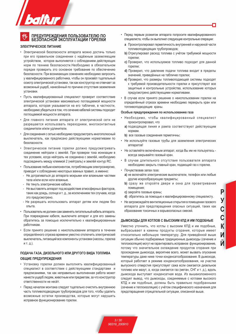
РУССКИЙ
3 / 3098319_200910
I ПРЕДУПРЕЖДЕНИЯ ПОЛЬЗОВАТЕЛЮ ПО БЕЗОПАСНОЙ ЭКСПЛУАТАЦИИ ГОРЕЛКИ
ЭЛЕКТРИЧЕСКОЕ ПИТАНИЕ• Электрической безопасности аппарата можно достичь только
при его правильном соединении с надёжным заземляющим устройством, которое выполняется с соблюдением действующих норм по технике безопасности.Необходимо в обязательном порядке проверить это основное требование по обеспечению безопасности. При возникающих сомнениях необходимо запросить у квалифицированного работника, чтобы он произвёл тщательный осмотр электрической установки, так как конструктор не отвечает за возможный ущерб, нанесённый по причине отсутствия заземления установки.
• Пусть квалифицированный специалист проверит соответствие электрической установки максимально поглащаемой мощности аппарата, которая указывается на его табличке, в частности, необходимо убедиться в том, что сечение кабелей системы подходит поглощаемой мощности аппарата.
• Для главного питания аппарата от электрической сети не разрешается использовать переходники, многоконтактные соединители и/или удлинители.
• Для соединения с сетью необходимо предусмотреть многополюсный выключатель, как предписано действующими нормативами по безопасности.
• Электрическое питание горелки должно предусматривать соединение нейтрали с землёй. При проверки тока ионизации в тех условиях, когда нейтраль не соединена с землёй, необходимо подсоединить между клеммой 2 (нейтраль) и землёй контур RC.
• Пользование любым компонентом, потребляющим электроэнергию, приводит к соблюдению некоторых важных правил, а именно:
- Не дотрагиваться до аппарата мокрыми или влажными частями тела и/или если ноги влажные.
- Не тянуть электрические кабели. - Не выставлять аппарат под воздействие атмосферных факторов,
таких как дождь, солнце и т. д., за исключением тех случаев, когда это предусмотрено.
- Не разрешать использовать аппарат детям или людям без опыта.
• Пользователь не должен сам заменять питательный кабель аппарата. При повреждении кабеля, выключите аппарат и для его замены обратитесь за помощью исключительно к квалифицированным работникам.
• Если принято решение о неиспользовании аппарата в течении определённого отрезка времени уместно отключить электрический выключатель, питающий все компоненты установки (насосы, горелка и т. д.).
ПОДАЧА ГАЗА, ДИЗЕЛЬНОГО ИЛИ ДРУГОГО ВИДА ТОПЛИВА ОБЩИЕ ПРЕДУПРЕЖДЕНИЯ • Установку горелки должен выполнять квалифицированный
специалист в соответствии с действующими стандартами и предписаниями, так как неправильно выполненная работа может нанести ущерб людям, животным или предметам, за что конструктор ответственности не несёт.
• Перед началом монтажа следует тщательно очистить внутреннюю часть топливоподводящих трубопроводов для того, чтобы удалить возможные остатки производства, которые могут нарушить исправное функционирование горелки.
• Перед первым розжигом аппарата попросите квалифицированного специалиста, чтобы он выполнил следующие контрольные операции:
a Проконтролировал герметичность внутренней и наружной части топливоподводящих трубопроводов;
b) Отрегулировал расход топлива с учётом требуемой мощности горелки;
c) Проверил, что используемое топливо подходит для данной горелки;
d) Проверил, что давление подачи топлива входит в пределы значений, приведённых на табличке горелки;
e) Проверил, что размеры топливоподающей системы подходят к требуемой производительности горелки и присутствуют все защитные и контрольные устройства, использование которых предусмотрено действующими нормативами.
• В случае если принято решение о неиспользовании горелки на определённый отрезок времени необходимо перекрыть кран или топливоподводящие краны.
Особые предупреждения по использованию газа • Необходимо, чтобы квалифицированный специалист
проконтролировал, что a) подводящая линия и рампа соответствуют действующим
нормам. b) все газовые соединения герметичны;• Не используйте газовые трубы для заземления электрических
аппаратов! • Не оставляйте включённым аппарат, когда Вы им не пользуетесь -
всегда закрывайте газовый кран.• В случае длительного отсутствия пользователя аппарата
необходимо закрыть главный кран, подающий газ к горелке.• Почувствовав запах газа: a) не включайте электрические выключатели, телефон или любые
другие искрообразующие предметы; b) сразу же откройте двери и окна для проветривания
помещения; c) закройте газовые краны; d) обратитесь за помощью к квалифицированному специалисту. • Не загромождайте вентиляционные открытия в помещении газового
аппарата для предотвращения опасных ситуаций, таких как образование токсичных и взрывоопасных смесей.
ДЫМОХОДЫ ДЛЯ КОТЛОВ С ВЫСОКИМ КПД И ИМ ПОДОБНЫЕ Уместно уточнить, что котлы с высоким КПД и им подобные, выбрасывают в камины продукты сгорания, которые имеют относительно небольшую температуру. Для приведённой выше ситуации обычно подбираемые традиционные дымоходы (сечение и теплоизоляция) могут не гарантировать исправное функционирование, потому что значительное охлаждение продуктов сгорания при прохождении дымохода, вероятнее всего, может вызвать опускание температуры даже ниже точки конденсатообразования. В дымоходе, который работает в режиме конденсатообразования, на участке выпускного отверстия присутствует сажа если сжигается дизельное топливо или мазут, а, когда сжигается газ (метан, СНГ и т. д.), вдоль дымохода выступает конденсатная вода. Из вышеизложенного следует вывод, что дымоходы, соединяемые с котлами высокого КПД и им подобные, должны быть правильно подобранными (сечение и теплоизоляция) с учётом специфического назначения для предотвращения отрицательной ситуации, описанной выше.

РУССКИЙ
4 / 3098319_200910
Btèyvztxrvt èfhfrbthvxbvrv cjltknBT 75 DSPG BT 100 DSPG BT 120 DSPG
hfxèjl cvy. ru/z 35 45 40
cfrx. ru/z 75 100 140
Btgkjdf< cjoyjxbncvy. rdb 474 533 439
cdrx. rdb 889 1186 1838
d<prjxbn ujhùztuj ufpjqkn 1,5°E ghv 20°C ldvufbtkn dtybvk<bjhf 230/400 d- 50 uw 1,1 rdb 1,5 rdb 2,2 rdb
Bhfyxajhcfbjh djknb 10 rd-30cf 10 rd-30cf 12 rd 30cf
yfgh<òtyvt Bhtèafpyjt 3~ 230/400 d- 50 uw
Rjcgktrb ghvyflktòyjxbtq
rhtgtòysq akfytw ujhtkrv N° 1 N° 2
vpjk<wvjyyf< ghjrkflrf N° 1
°kfxbvzysq èjceb - - N° 1
Igvknrv N°4 M12 N°4 M16 N°4 M16
ufqrv itxbvuhfyyst N°4 M12 N°4 M16 N°4 M16
Gkjxrvt rjknwtdst ghjrkflrv N°4 Ø12 N°4 Ø16 N°4 Ø16
Bhems uvmrvt N°2 - 1” x1" N°2 - 1” x1" N°2 - 1” x1"
Gfbhemrv N°2 - 1” x1" N°2 - 1” x1" N°2 - 1” x1"
avknbh 1” 1” 1”
Btèyvztxrvt èfhfrbthvxbvrv cjltknBT 180 DSPG BT 250 DSPG BT 300 DSPG
hfxèjl cvy. ru/z 60 74 110
cfrx. ru/z 180 270 325
Btgkjdf< cjoyjxbncvy. rdb 712 873 1304
cdrx. rdb 2135 3186 3854
d<prjxbn ujhùztuj ufpjqkn 1,5°E ghv 20°C ldvufbtkn dtybvk<bjhf 230/400 d- 50 uw 3 rdb 7,5 rdb 7,5 rdb
Bhfyxajhcfbjh djknb 14rd-30cf 14rd-30cf 14rd 30cf
yfgh<òtyvt Bhtèafpyjt 3~ 230/400 d- 50 uw
Rjcgktrb ghvyflktòyjxbtq
rhtgtòysq akfytw ujhtkrv N°1 N°1 N°1
vpjk<wvjyyf< ghjrkflrf N°1 N°1 N°1
°kfxbvzysq èjceb - - - - - -
Igvknrv N°4 M12 N°4 M12 N°4 - M20
ufqrv itxbvuhfyyst N°4 M12 N°4 M12 N°4 - M20
Gkjxrvt rjknwtdst ghjrkflrv N°4 Ø12 N°4 Ø12 N°4 - M20
Bhems uvmrvt N°2 - 1”1/4 x 1"1/4 N°2 1" x 1" N°2 - 1”1/4 x 1"1/4
Gfbhemrv - - - - - -
avknbh 1”1/4 1”1/4 1”1/4
Btèyvztxrvt èfhfrbthvxbvrv v ufmfhvbyst hfpcths ujhtkjr cjltktq

РУССКИЙ
5 / 3098319_200910
N° 0002270035Btèyvztxrvt èfhfrbthvxbvrv v ufmfhvbyst hfpcths ujhtkjr cjl-tktq
cjltkn A A1 A2 B B1 B2 C D E F I I1 L M N cvy. cfrx. Ø ØBT 75 DSPG 595 310 385 510 365 145 1215 130 ÷ 450 205 160 260 260 225 ÷ 300 M12 170BT 100 DSPG 670 330 340 525 365 160 1415 210 ÷ 400 230 195 320 - 276 M16 240BT 120 DSPG 770 390 380 610 450 160 1415 155 ÷ 500 230 195 320 - 276 M16 240BT 180 DSPG 815 390 425 650 450 200 1700 200 ÷ 535 260 220 320 320 280÷370 M12 230BT 250 DSPG 1000 520 480 740 580 160 1700 235 ÷ 560 260 220 320 320 280÷370 M12 230BT 300 DSPG 1000 520 480 800 580 220 1900 245 ÷ 605 360 275 440 440 400÷540 M20 365
1) yfxjx2) htuekvheùovq rkfgfy lfdktyv<3) cjlek<bjh4) ajbjxjghjbvdktybt5) Bhfyxajhcfbjh pfòvufyv<6) ldvufbtkn dtybvk<bjhf
7) xctxvbtknyf< ujkjdrf8) vpjk<wvjyyf< ghjrkflrf9) rhtg\òysq akfytw ujhtkrv10) htuekvhjdjzysq dvyb gjlfzv djpleèf yf xctxvbtknyeù ujkjdre11) °ktrbhjovb12) °ktrbhjcfuyvb
BT 100 - 120 DSPG BT 75 - 180 - 250 - 300 DSPG
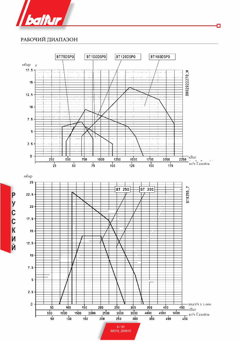
РУССКИЙ
6 / 3098319_200910
HFMJZVQ LVFGFPJY
cmfh
rdfb
ru/z ufpjqkn
cmfh
rdfbru/z ufpjqkn
rrfk/z è 1.000

РУССКИЙ
7 / 3098319_200910
СОЕДИНЕНИЕ ГОРЕЛКИ С КОТЛОМ
Rhtgktyvt ujhtkrv yf rjbkt. (Rhtgtòyst akfyws dsgjkytyys vp xbfkv) lk< cjl. BT 75 - 100 - 120 DSPG
! Äëÿ çàòÿæêè ôëàíöà ñëåäóåò ïðèïîäíÿòü êîðïóñ ãîðåëêè òàê, ÷òîáû íàêîíå÷íèê ãîðåëêè íàõîäèëñÿ â ãîðèçîíòàëüíîì ïîëîæåíèè. Ôëàíåö ñëåäóåò çàêðåïèòü íà íàêîíå÷íèêå ãîðåëêè â ïîëîæåíèè, îáåñïå÷èâàþùåì ïðîíèêíîâåíèå åãî â òîïî÷íóþ êàìåðó (ãëóáèíà ïðîíèêíîâåíèÿ íàêîíå÷íèêà óêàçûâàåòñÿ èçãîòîâèòåëåì êîòëà).
Êðåïëåíèå ãîðåëêè ê êîòëó äëÿ ìîäåëåé BT 180 - 250 - 300 DSPG
N° 00
0293
3330
XVXBtcF GVBFYV< uJHùZVc
yfxjx ujhtkrv ljkòty gjkezfbn ujhùztt zthtp xvxbtce gjlfzv bjgkvdf, xyfmòtyyeù dxgjcjufbtknysc yfxjxjc x ghtlexcjbhtyysc htuek<bjhjc lfdktyv<, htuekvhetcsq jb 0,2 mfh lj 1 mfhf (xc. 0002901120).d lfyyjc xkezft dtkvzvyf lfdktyv< gjlfzv ujhùztuj yf yfxjx ujhtkrv (0,2 - 1 mfh) ljkòyf msbn ytvpctyyjq rfr ghv dsrkùztyyjq ujhtkrt, bfr v ghv hfmjbfùotq ujhtkrjq yf cfrxvcfknyjq gjlfzt ujhùztuj, pfghjityyjq rjbkjc.lfyyeù xvxbtce gvbfyv< cjòyj dsgjkyvbn mtp htuek<bjhf lfdktyv<, vxgjknpe< ghvywvgvfknyeù xètce dB 8666/3.xvxbtcf gvbfyv< ljkòyf msbn dsgjkytyf rfr erfpfyj d yfivè xètcfè xc. 0002901120 vkv òt dB 8666/3.jghtltktyvt hfpcthjd bhem ljkòyj msbn ghjvpdtltyj d pfdvxvcjxbv jb vè lkvys v jb cjoyjxbv vxgjknpetcjuj yfxjxf.yfiv erfpfyv< rfxfùbx< bjknrj xbhjuj ytjmèjlvcjuj lk< jmtxgtztyv< èjhjituj ghjwtxxf hfmjbs.
ÝËÅÊÒÐÈ×ÅÑÊÈÅ ÑÎÅÄÈÍÅÍÈß
Æåëàòåëüíî, ÷òîáû âñå ñîåäèíåíèÿ áûëè âûïîëíåíû ãèáêèì ýëåêòðè÷åñêèì ïðîâîäîì. Ýëåêòðè÷åñêèå ïðîâîäà äîëæíû áûòü óäàëåíû îò ãîðÿ÷èõ ÷àñòåé. Óáåäèòåñü, ÷òî ýëåêòðîñåòü, ê êîòîðîé âû õîòèòå ïðèñîåäèíèòü àïïàðàòóðó, èìååò íàïðÿæåíèå è ÷àñòîòó, ïîäõîäÿùèå äëÿ ãîðåëêè. Óáåäèòåñü, ÷òî îñíîâíàÿ ëèíèÿ, ñîîòâåòñòâóþùèé âûêëþ÷àòåëü ñ ïðåäîõðàíèòåëÿìè (îáÿçàòåëüíû) è âîçìîæíûé îãðàíè÷èòåëü ñïîñîáíû âûäåðæèâàòü ìàêñèìàëüíûé òîê, ïîòðåáëÿåìûé ãîðåëêîé. Ïîäðîáíîñòè ñì. íà ýëåêòðè÷åñêèõ ñõåìàõ äëÿ êàæäîé îòäåëüíîé ãîðåëêè.
1. xbfyvyf rjbkf2. akfytw vp vpjk<wvjyyjuj cfbthvfkf3. akfyws rhtgktyv< ujhtkjr4. éjceb àkfxbvzysq5. Igvknrf6. ufqrf v rjknwtdf< ghjrkflrf mkjrvhjdrv7. ufqrf v rjknwtdf< ghjrkflrf rhtgktyv<
gthdjuj akfywf
1 - Крепёжные фланцы горелок2 - Изоляционный шнур3 - Фланец из изоляционного материала4 - Плита котла5 - Шпильки, шайбы и гайки для крепления к котлу6 - Шпильки, шайбы и гайки для крепления к котлу7 - Гайки винты и стопорные шайбы для крепления фланца к стакану

РУССКИЙ
8 / 3098319_200910
N° 0002901120rev.: 19/02/2002
N° BT 8666/3
Ghvywvgvfknyf< xètcf uvlhfdkvztxrjuj gvbfyv< lk< ytxrjknrvè ujhtkjr, hfmjbfùovè yf ufpjqkt vkv ujhùzvè cfxkfè x yjcvyfknyjq d<prjxbnù cfr-xvcec jb 5•T lj 50•T
Ghvywvgvfknyf< xètcf uvlhfdkvztxrjuj gvbfyv< gjl lfdktyvtc lk< ldeè afrtknysè ujhtkjr, vkv cjlekvhjdfyysè yf ufpjqkt
! htpthdefhs lk< gjdbjhyjuj vxgjknpjdfyv< ufpjqk< (lvfctbh ~ 150 dsxjbf ~ 400) ljkòys exbfyfd-kvdfbnx< rfr cjòyj mkvòt r ujhtkrt, ghvcthyj yf 0,5 c dsit yfxjxf ujhtkrv.
1 - ÃËÀÂÍÛÉ ÐÅÇÅÐÂÓÀÐ
2 - ÔÈËÜÒÐ
3 - ÖÈÐÊÓËßÖÈÎÍÍÛÉ ÍÀÑÎÑ
4 - ÑËÈÂ ÂÎÄÛ È ÑÈÑÒÅÌÀ
5 - ÂÛÏÓÑÊ ÂÎÇÄÓÕ-ÃÀÇ ÎÁÛ×ÍÎ ÇÀÊÐÛÒ
6 - ÁÀÊ ÐÅÊÓÏÅÐÈÐÎÂÀÍÍÎÃÎ
ÒÎÏËÈÂÀ È ÄÅÃÀÇÀÒÎÐ
7 - ÎÁÐÀÒÍÛÉ ÊËÀÏÀÍ
8 - ÁÀÉÏÀÑ (ÎÁÛ×ÍÎ ÇÀÊÐÛÒ)
9- ÐÅÃÓËßÒÎÐ ÄÀÂËÅÍÈß ÄÈÀÏÀÇÎÍ ÐÅÃÓËÈÐÎÂÊÈ 0,2-1 ÁÀÐ
10- ÌÀÍÎÌÅÒÐ (0-4 ÁÀÐ)
1 - ÃËÀÂÍÛÉ ÐÅÇÅÐÂÓÀÐ
2 - ÔÈËÜÒÐ
3 - ÖÈÐÊÓËßÖÈÎÍÍÛÉ ÍÀÑÎÑ
4 - ÑËÈÂ ÂÎÄÛ È ÑÈÑÒÅÌÀ
5 - ÂÛÏÓÑÊ ÂÎÇÄÓÕ-ÃÀÇ ÎÁÛ×ÍÎ ÇÀÊÐÛÒ
6 - ÁÀÊ ÐÅÊÓÏÅÐÈÐÎÂÀÍÍÎÃÎ
ÒÎÏËÈÂÀ È ÄÅÃÀÇÀÒÎÐ
7 - ÎÁÐÀÒÍÛÉ ÊËÀÏÀÍ
8 - ÁÀÉÏÀÑ (ÎÁÛ×ÍÎ ÇÀÊÐÛÒ)
! htpthdefhs lk< gjdbjhyjuj vxgjknpjdfyv< ufpjqk< (lvfctbh ~ 150 dsxjbf ~ 400) ljkòys exbfyfd-kvdfbnx< rfr cjòyj mkvòt r ujhtkrt, ghvcthyj yf 0,5 c dsit yfxjxf ujhtkrv.
РУССКИЙ
9 / 3098319_200910
Jgvxfyvt aeyrwvjyvhjdfyv< ujhtkjr yf ufpjqkt (xc.DB 8714/2)
Yfpsdfùbx< ldeèxbflvqyst gjxktljdfbtknyjq htuekvhjdrv, b.r. gthtèjl x gthdjuj yf dbjhjt gkfc< (x cvyvcfknyjuj htòvcf hfmjbs yf cfrxvcfknyj exbfyjdk-tyysq) ghjvxèjlvb gjxbtgtyyj, rfr ghvbjr djpleèf, gjllthòvdfùotuj xujhfyvt, bfr v gjlfzf ujhùztuj.Ghvmjh eghfdktyv< v rjybhjk< (wvrkvztxrjt htkt) ujhtkrv gjlrkùzftbx< ghv gjcjov dsrkùzfbtk< yf hfx-ghtltkvbtknyjc ovbt (1).Ghvmjh eghfdktyv< v rjybhjk< d dvlt wvrkvztxrjuj htkt ghjvpdjlvb ghjuhfcce pfòvufyv< gjlrkùzf< ldvufbtkn dtybvk<bjhf f xktljdfbtknyj v yfxjx lk< ghjdtltyv< afps ghtldfhvbtknyjq ghjledrv v htwvhrek<wvv ufpjqk<.Yfxjx gjlftb ufpjqkn yf eptk hfxgsktyv<, d rjbjhjc bjgkvdj ghjljkòftb wvhrekvhjdfbn mtp dsèjlf yfheòe, gjbjce zbj ghjèjls d yfghfdktyvt r ajhxeyrt (gjl-fzf) v vp ajhxeyrv (djpdhfb) pfrhsbs.Pfrhsbvt ghjvxèjlvb ghv gjcjov pfbdjhysè igvktr®, hfxgjkjòtyysè yf rjywfè b<u.Lfyyst igvknrv® ghvòfbs r xjjbdtbxbdeùovc xtlkfc ghv gjcjov òtxbrvè gheòvy, hfxgjkjòtyysè yf ghjbvdjgjkjòysè rjywfè b<u.ufpjqkn wvhrekvhetb v dsèjlvb zthtp djpdhfb epkf hfxgsktyv< yf htuek<bjh lfdktyv< djpdhfbf, ghjèjl-vbn zthtp ytuj v ljxbvuftb djpdhfbf yfxjxf, vp rjbjhjuj dsèjlvb yf djpdhfb.Dsitjgvxfyyf< wvhrek<wv< ufpjqk< ghjvpdjlvbx< x dtkvzvyjq lfdktyv< ytcyjuj dsit (ytxrjknrj mfh) cvyvcfknyjuj lfdktyv<, yf rjbjhjt jbhtuekvhjdfy htuek<bjh lfdktyv< djpdhfbf (10-12 mfh).Ghjljkòvbtknyjxbn afps ghtldfhvbtknyjq dtybvk<wvv v ghtldfhvbtknyjq wvhrek<wvv ufpjqk< yt xjjbdtbxb-deùb 22,5 xtr., ghtlexcjbhtyysc ghvmjhjc eghfdktyv< v rjybhjk<, gjbjce zbj lfyyf< jgthfwv< ghjvpdjlvbx< x djpleiyjq pfxkjyrjq d jbrhsbjc gjkjòtyvv.Dhtc< ght-dtybvk<wvv v ght-wvhrek<wvv <dk<tbx< htpeknbfbjc xeccs dhtctyv, eitlituj yf xktleùovt ltqxbdv<:-éjl jbrhsbv< ldvufbtk< cjlek<wvv (45 xtr.) + dhtc< ghtldfhvbtknyjq dtybvk<wvv, ghtlexcjbhtyyjt ghvmjhjc eghfdktyv< (22,5 xtr.) + èjl pfrhsbv< ldvufbtk< cjlek<wvv lj gjkjòtyv< djpleèf pfòvufyv< (jrjkj 40 xtr.)D htpeknbfbt, ghjljkòvbtknyjxbn ghtldfhvbtknyjq dtybvk<wvv v ghtldfhvbtknyjq wvhrek<wvv ufpjqk< gjkezftbx< ult-bj jrjkj 107 xtr.Pfbtc, ghvmjh eghfdktyv< ghjljkòftb ghjdtltyvt ghjuhfccs ghjwtxxf pfòvufyv< gebtc gjlrkùztyv< bhfyxajhcfbjhf pfòvufyv<, rjbjhsq gjlftb bjr dsxjrjuj yfgh<òtyv< yf àktrbhjls.Dsxjrjt yfgh<òtyvt ctòle àktrbhjlfcv ghjdjwvhetb àktrbhvztxrvq hfph<l (vxrhf) lk< hjpòvuf xctxv ujhùztt - djpleè.Gjxkt 2.5 xtreyl x yfzfkf gjlfzv vxrhs pfòvufyv< ghvmjh eghfdktyv< gjlftb yfgh<òtyvt yf cfuyvb, rjbjhsq, ghv gjcjov xjjbdtbxbdeùotq xvxbtcs hszfujd, jbb<uvdftb yfpfl jmt b<uv, gthtrhsdfùovt ghjèjl (gjlfzv v djpdhfbf) ufpjqk< r ajhxeyrt.Jbb<uvdfyvt b<u ghvdjlvb v r gthtrhsbvù dyebhtyytuj gthtgexrf (mfq-gfxxf) d epkt hfxgsktyv<, d htpeknbfbt
ztuj lfdktyvt yfxjxf exbfyfdkvdftbx< yf yjhcfknyjc pyfztyvv 20 - 22 mfh.B<uv jbòvcfùb pfbdjhyst igvknrv jb vè xtltk, gjpdjk<< btc xfcsc bjgkvde gjxbegvbn yf ajhxeyre gjl jbhtuekvhjdfyysc yfxjxjc lfdktyvtc d 20-22 mfh v dsqbv vp ytt d eòt hfxgsktyyjc xjxbj<yvv.Lfdktyvt djpdhfbf, jghtltk<ùott gjlfze bjgkvdf d bj-gre, htuekvhetbx< htuek<bjhjc lfdktyv< djpdhfbf.Pyfztyvt hfxèjlf lk< pfòvufyv< (cvyvcfknyf< gjlfzf) ghvmkvpvbtknyj 10-12 mfh.Hfxgsktyysq ufpjqkn, dsèjl<ovq vp ajhxeyrv, xc-tivdftbx< x yfuytbftcsc dtybvk<bjhjc djpleèjc v djxgkfcty<tbx< vxrhjq jb àktrbhjljd.Yfkvzvt gkfctyv avrxvhetbx< ajbjxjghjbvdktyvtc.Ghjuhfccyjt exbhjqxbdj ghjljkòftb ghjdtltyvt pfl-fyyjq ghjuhfccs v, gjxkt 5 xtr., ghjql< gjkjòtyvt mkjrvhjdrv, jbrkùzftb pfòvufyvt v gjlrkùzftb xvxbtce cjlek<wvv.Ldvufbtkn cjlek<bjhf gjlftb xvuyfk yf edtkvztyvt jlyjdhtctyyjq gjlfzv ujhùztuj bjgkvdf v djpleèf, gjllthòvdfùotuj ujhtyvt.Edtkvztyvt gjlfzv ufpjqk< jghtltk<tbx< lvxrjc x gthtctyyscv ghjavk<cv, rjbjhsq dhfof<xn ghjvpdjl-vb ljgjkyvbtknyjt edtkvztyvt xòfbv< gheòvys htuek<bjhf lfdktyv< djpdhfbf v, xktljdfbtknyj, edtkvztyvt xfcjuj lfdktyv<; edtkvztyvù lfdktyv< djpdhfbf xjjbdtbxbdetb edtkvztyvt gjldfzv bjgkvdf.Edtkvztyvù gjlfzv ufpjqk< ljkòyj xjjbdtbxbdjdfbn edtkvztyvù, yf ljkòyeù dtkvzvye, gjlfzv djpleèf lk< xujhfyv<.Jlyjdhtctyyf< gjlfzf ujhùztuj v djpleèf lk< xujhfyv< edtkvzvdfùbx< dgkjbn lj ljxbvòtyv< cfrxvcfknyjuj pyfztyv< (lfdktyvt ufpjqk< yf htuek<bjht lfdktyv< djpdhfbf xjxbfdk<tb ghvmkvpvbtknyj 18-20 mfh, txkv lfdktyvt yf yfxjxt vcttb dtkvzvye 20-22 mfh).Gjlfzf ujhùztuj v djpleèf lk< xujhfyv< jxbfùbx< yf cfrxvcfknyjc ehjdyt lj btè gjh, gjrf btcgthfbehf (lfdktyvt, txkv rjbtk gfhjdjq) rjbkf yt ghvmkvpvbx< r pyfztyvù, yf rjbjhjt jbhtuekvhjdfy bthcjxbfb (vkv ghtxxjxbfb) 2-q xbflvv, dspsdf< btc xfcsc ldvòtyvt xthdjghvdjlf htuekvhjdrv gjlfzv (ujhùztt/djpleè) d ghjbvdjgjkjòyjc yfzfknyjce yfghfdktyvv, gjxbtgtyyj ectynif< gjlfze ufpjqk< v jbyjxvbtknyj djpleèf lk< xujhfyv< lj cvyvcfknyjuj pyfztyv<.D xkezft, txkv lfòt ghv cvyvcfknyjq gjlfzt ujhùztuj v djpleèf lk< xujhfyv< btcgthfbehf (lfdktyvt, txkv rjbtk gfhjdjq) ljxbvuytb cfrxvcfknyjuj pyfztyv<, xhfmjbftb, ghv dtkvzvyt, yf rjbjheù jy jbhtuekvhjdfy, bthcjxbfb (ghtxxjxbfb, txkv rjbtk gfhjdjq), dspsdf< gjkyeù jxbfyjdre ujhtkrv.Ghv gjyvòtyvv btcgthfbehs (lfdktyv<, txkv rjbtk gfhjdjq) yvòt gfhfctbhf, ghv rjbjhjc xhfmjbfk ctèfyvpc jbrkùztyv<, ujhtkrf dyjdn drkùzftbx<, rfr jgvxfyj dsit.Ghv yjhcfknyjc aeyrwvjyvhjdfyvv bthcjxbfb (vkv ghtxxjxbfb) 2-q xbflvv ghtleghtòlftb gthtctye yfuhe-prv rjbkf v fdbjcfbvztxrv gjlftb pfghjx xthdjghvdj-le htuekvhjdrv gjlfzv (ujhùztuj bjgkvdf/djpleèf) lk< xjhfpcthyjq gjlfzv ufpjqk< v xjjbdtbxbdeùotuj djpleèf lk< xujhfyv<. Ghv gjljmyjq gjxktljdfbtknyjxbv, xvxbtcf htuekvhjdfyv< gjlfzv (ujhùztuj/djpleèf) ljxbvuftb gjkjòtyv< hfdyjdtxv<, rjbjhjt xjjbdtbxbdetb gjlfzt ujhùztuj v djpleèf lk< xujhfyv< hfdyjq rjkvztxbde
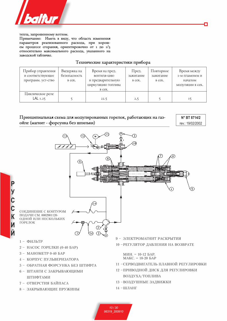
РУССКИЙ
10 / 3098319_200910
btgkf, pfghjityyjce rjbkjc.Ghvctzfyvt: Vctbn d dvle, zbj jmkfxbn vpctytyv< gfhfctbhjd htfkvpjdfyyjuj hfxèjlf, ghv èjhji-tc ghjwtxxt xujhfyv<, jhvtybvhjdjzyj jb 1 lj 1/3 jbyjxvbtknyj cfrxvcfknyjuj hfxèjlf, erfpfyyjuj yf pfdjlxrjq bfmkvzrt.
Btèyvztxrvt èfhfrbthvxbvrv ghvmjhf
Ghvywvgvfknyf< xètcf lk< cjlekvhjdfyysè ujhtkjr, hfmjbfùovè yf ufp-jqkt (cfuyvb - ajhxeyrf mtp igvknrv)
N° BT 8714/2rev.: 19/02/2002
Ghvmjh eghfdktyv< v xjjbdtbxbdeùott ghjuhfcc. exb-xbdj
wvrkvztxrjt htktLAL 1.25
dslthòrf yf mtpjgfxyjxbn
d xtr.
5
dhtc< yf ghtl.dtybvk<-wvù
v ghtldfhvbtknyeù wvhrek<wvù bjgkvdf
d xtr.
22.5
Ghtl.pfòvufyvt
d xtr.
2,5
Gjdbjhyjt pfòvufyvt
d xtr.
5
dhtc< ctòle 1-c gkfctytc v
yfzfkjc cjlek<wvv d xtr.
15
1 – ÔÈËÜÒÐ
2 – ÍÀÑÎÑ ÃÎÐÅËÊÈ (0-40 ÁÀÐ)
3 – ÌÀÍÎÌÅÒÐ 0-40 ÁÀÐ
4 – ÊÎÐÏÓÑ ÏÓËÜÂÅÐÈÇÀÒÎÐÀ
5 – ÎÁÐÀÒÍÀß ÔÎÐÑÓÍÊÀ ÁÅÇ ØÒÈÔÒÀ
6 – ØÒÀÍÃÈ Ñ ÇÀÊÐÛÂÀÞÙÈÌÈ
ØÒÈÔÒÀÌÈ
7 – ÎÒÂÅÐÑÒÈß ÁÀÉÏÀÑÀ
8 – ÇÀÊÐÛÂÀÞÙÈÅ ÏÐÓÆÈÍÛ
ÑÎÅÄÈÍÅÍÈÅ Ñ ÊÎÍÒÓÐÎÌ ÏÎÄÀ×È ÑÌ. 0002901120-ÎÄÍÎÉ ÈËÈ ÍÅÑÊÎËÜÊÈÕ ÃÎÐÅËÎÊ
9 – ÝËÅÊÒÐÎÌÀÃÍÈÒ ÐÀÑÊÐÛÒÈß
10 – ÐÅÃÓËßÒÎÐ ÄÀÂËÅÍÈß ÍÀ ÂÎÇÂÐÀÒÅ
ÌÈÍ. = 10-12 ÁÀÐ, ÌÀÊÑ. = 18-20 ÁÀÐ
11 – ÑÅÐÂÎÄÂÈÃÀÒÅËÜ ÏËÀÂÍÎÉ ÐÅÃÓËÈÐÎÂÊÈ
12 – ÏÐÈÂÎÄÍÎÉ ÄÈÑÊ ÄËß ÐÅÃÓËÈÐÎÂÊÈ
ÂÎÇÄÓÕÀ/ÒÎÏËÈÂÀ
13 – ÂÎÇÄÓØÍÛÅ ÇÀÄÂÈÆÊÈ
14 – ØËÀÍÃ

РУССКИЙ
11 / 3098319_200910
N° 00
0290
0580
ÍÀÑÎÑ ÔÈÐÌÛ BALTUR ÌÎÄÅËÜ ÂÒ.....
Âñàñûâàíèå Óçåë êðåïëåíèÿ âàêóóììåòðà 1/4’
Îáðàòíàÿ òðóáà
Çàâîäñêàÿ òàáëè÷êà íàñîñà
Ðåãóëèðîâàíèå äàâëåíèÿ íàñîñà (20÷22 áàð)
Íàãíåòàíèå (ôîðñóíêà)
Óçåë êðåïëåíèÿ ìàíîìåòðà 1/4’
Ãíåçäî íàãðåâàþùåãî ýëåìåíòà
Âñàñûâàíèå Óçåë êðåïëåíèÿ âàêóóììåòðà 1/4’
Îáðàòíàÿ òðóáà
Ðåãóëèðîâàíèå äàâëåíèÿ íàñîñà (20 ÷ 22 áàð)
Íàãíåòàíèå (ôîðñóíêà)
Óçåë êðåïëåíèÿ ìàíîìåòðà 1/4’
Çàâîäñêàÿ òàáëè÷êà íàñîñà
Ãíåçäî íàãðåâàþùåãî ýëåìåíòà
N° B
T 93
53/1
ФОРСУНКА (CB) CHARLES BERGONZO ДЕМОНТИРОВАННАЯ (БЕЗ ИГЛЫ)Опознавательные данные форсунки:Расход в кг/ч Угол распыления (30°-45°-60°-80°) Соотношение расхода (1/3 = B3 – 1/5 = B5) Уплотнительное кольцо из витона
(устойчивость к маслу и высокой температуре) Камера завихрения
Обратная линия топливаОтверстие выхода топлива
Отверстие обратки топливаПРИМ. Для хорошей работы форсунки необходимо, чтобы ее обратная линия никогда не была полностью закрытой. Это условие
необходимо обеспечить при первом розжиге горелки, выполняя соответствующие операции, а именно: когда форсунка работает на требуемом максимальном расходе, разница давления между подающей (давление насоса) и обратной линиями форсунки (давление на регуляторе давления обратной линии) было по крайней мере 2-3 бара.
Например: Давление насоса 20 бар Давление насоса 22 бара Давление обратной линии 20-2 = 18 бар Давление обратной линии 22-3 = 19 бар Давление обратной линии 20-3 = 17 бар Давление обратной линии 22-2 = 20 бар
Вход топлива

РУССКИЙ
12 / 3098319_200910
pfòvufyvt v htuekvhjdfyvt ujhtkjr, hfmjBfùovè yf ufpjqkt
1) Ghjdthvbn, zbjms btèyvztxrvt èfhfrbthvxbvrv ajhxeyrv (gjlfzf v eujk hfxgsktyv<) xjjbdtbxb-djdfkv bjgrt (xc. db 9353/1). d ghjbvdyjc xkezft pfctyvbn ajhxeyre yf gjlèjl<oeù.
2) emtlvbnx< d yfkvzvv ujhùztuj d wvxbthyt, v zbj jyj, gj rhfqytq ctht dvpefknyj, ghvujlyj lk< lfyyjq ujhtkrv.
3) Ghjdthvbn yfkvzvt djls d rjbkt v emtlvbnx<, zbjms pfxkjyrv exbfyjdrv mskv jbrhsbscv.
4) emtlvbnx<, zbjms dsmhjx ghjlerbjd xujhfyv< ghjvxèjlvk mtpghtg<bxbdtyyj (pfxkjyrv rjbkf v lscjèjlf jbrhsbs).
5) Ghjdthvbn, zbjms yfgh<òtyvt yf kvyvv àktr-bhjgthtlfzv, r rjbjhjq ljkòyj msbn ghjvpdtltyj gjlrkùztyvt, xjjbdtbxbdjdfkj bjce, rjbjhjt er-fpfyj rjyxbherbjhjc, v àktrbhvztxrvt xjtlvytyv< gjkyjxbnù xjjbdtbxbdeùb vctùotqx< dtkvzvyt yfgh<òtyv<.
Ghjdthvbn bfròt, zbjms dxt àktrbhvztxrvt xjtl-vytyv<, xltkfyyst yf ctxbt, mskv ghfdvknyj dsgjkytys, d xjjbdtbxbdvv x yfivcv àktrbhvztxr-vcv xètcfcv.
6) emtlvbnx<, zbjms xctxvbtknyf< ujkjdrf mskf ljxbfbjzyjq lkvys lk< tt ddtltyv< dyebhn bjgrv yf dtkvzvye, ghtlexcjbhtyyeù rjyxbherbjhjc rjbkf.
Ghjdthvbn, zbjms exbhjqxbdj htuekvhjdrv djpleèf yf xctxvbtknyjq ujkjdrt, yfèjlvkjxn d gjkjòtyvv, gj-dfitce gjlèjl<otc, lk< bhtmetcjq gjlfzv ujhùztuj (ghjèjlyjt jbdthxbvt djpleèf ctòle lvxrjc v ujkjdrjq ljkòyj msbn pyfzvbtknyj pfrhsbj d xkezft jbyjxvbtknyj yvprjq gjlfzv ujhùztuj, d jmhfbyjc xkezft, rjulf ajhxeyrf vcttb gjlfze pyfzvbtknyj dsxjreù, ghjèjlyjt jbdthxbvt djpleèf ctòle lvxrjc v ujkjdrjq ljkòyj msbn pyfzvbtknyj jbrh-sbsc) xcjbhvbt hfpltk htuekvhjdfyvt xctxvbtknyjq ujkjdrv®.
7) xy<bn ghtljèhfyvbtknyeù rhsire x dhfofùo-tujx< lvxrf, exbfyjdktyyjuj yf cvrhjldvufbtkn cjlekvhjdfyv<, yf rjbjhjc hfxgjkfufùbx< htu-vxbhfwvjyyst dvybs ghtlyfpyfztyyst lk< eghfdk-tyv< gjlfzv ujhùztuj v xjjbyjxvbtknyjuj djpleèf, gjllthòvdfùotuj xujhfyvt.
8) exbfyjdvbn ldf gthtrkùzfbtk< cjlek<bjhf d gjkjòtyvt “MIN” (cvyvcfknysq) v “MAN” (hezyjt).
9) ddtxbv d ltqxbdvt dxgjcjufbtknyeù wtgn gvbfyv< ujhùztuj, btc xfcsc ghjdthvd t\ àaatrbvdyjxbn v jbhtuekvhjdfbn lfdktyvt ghvmkvpvbtknyj yf 1 mfh, txkv lfyyf< wtgn ghtlexcfbhvdftb htuek<bjh lfdk-tyv<.
10) emhfbn x yfxjxf rhsire, pfrhsdfùoeù uytplj gjlxjtlvytyv< dfreecctbhf, gjxkt ztuj xkturf jbrh-sbn pfldvòre, hfxgjkjòtyyeù yf bhemt gjldjlf
ujhùztuj. dsòlfbn lj btè gjh, gjrf ujhùztt yt yfzytb dsèjl-
vbn vp jbdthxbv< mtp djpleiysè gepshtq, gjxkt ztuj pfrhsbn pfldvòre.
11) exbfyjdvbn cfyjctbh (ghtltk vpcthtyv< jrjkj 3 mfh) d uytplj, ghtlexcjbhtyyjt yf yfxjxt, lk< gjlxjtl-vytyv< dfreecctbhf, lk< ghjdtltyv< rjybhjk< dtkvzvys lfdktyv<, x rjbjhsc ujhùztt gjxbegf-tb yf yfxjx ujhtkrv. exbfyjdvbn cfyjctbh (ghtltk vpcthtyv< jrjkj 30 mfh) d uytplj, ghtlexcjbhtyyjt yf yfxjxt, gjlxjtlvytyv< cfyjctbhf, lk< djpcjòyjxbv rjybhjk< hfmjztuj lfdktyv< xfcjuj yfxjxf.exbfyjdvbn cfyjctbh (ghtltk vpcthtyv< jrjkj 30 mfh) yf ghtlexcjbhtyyjt ctxbj gjlxjtlvytyv< yf htuek<bjht lfdktyv< djpdhfbf gthdjuj gkfctyv (xc. dB 8714/2) lk< rjybhjk< lfdktyv< djpdhfbf.
12) jbrhsbn dxt pfldvòrv v lheuvt djpcjòyst pfgjhyst ghvmjhs, exbfyjdktyyst yf bhemjghjdjlt ufpjqk<.
13) exbfyjdvbn gthtrkùzfbtkn, hfxgjkjòtyysq yf geknbt eghfdktyv<, d gjpvwvù "0® (jbrhsbj) v gjlfbn bjr yf kvyvù àktrbhjgthtlfzv, r rjbjhjq gjlrkùztyf ujhtkrf. Ghjdthvbn, yfòvcf< dhezyeù xjjbdtbxb-deùovq lvxbfywvjyysq dsrkùzfbtkn, zbjms ldvufbtkn dtybvk<bjhf v yfxjxf dhfofkx< d ljkòyjc yfghfdk-tyvv, d xkezft ytjmèjlvcjxbv, gjcty<bn ctxbfcv ldf ghjdjlf cfuvxbhfkv, lk< xctys yfghfdktyv< dhfotyv<.
14) ddtxbv d ltqxbdvt yfxjx ujhtkrv, yfòvcf< dhezyeù xjjbdtbxbdeùovq lvxbfywvjyysq dsrkùzfbtkn lj btè gjh, gjrf cfyjctbh, avrxvheùovq gjrfpfyvt hfmjztuj lfdktyv< yfxjxf, yt meltb gjrfpsdfbn kturjt lfdktyvt. yfkvzvt yvprjuj lfdktyv< d wtgv gjlb-dthòlftb ghjvpitlitt pfgjkytyvt.
15) drkùzvbn dsrkùzfbtkn geknbf eghfdktyv< lk< gjlfzv àythuvv yf ghvmjh eghfdktyv< v rjybhjk<.
txkv bthcjxbfbs (ghtljèhfyvbtknysq v rjbkf) pfrhsbs, gjlrkùzftbx< ghjuhfccyjt exbhjqxbdj ghvmjhf eghfdktyv<, rjbjhjt jghtltk<tb ddjl d ltqxbdvt, d xjjbdtbxbdvv x exbfyjdktyyjq ghjuhfc-cjq, rjcgjytybjd ctèfyvpcjd ujhtkrv. exbfyjdrf pfòòtbx< bfr, rfr àbj jgvxfyj d hfpltkt jgvxfyvt aeyrwvjyvhjdfyv<®
16) rjulf ujhtkrf aeyrwvjyvhetb yf cvyvcect®, ghjvpdjlvbx< htuekvhjdrf djpleèf yf dtkvzvye, ytjmèjlvceù lk< jmtxgtztyv< èjhjituj xujhfyv<, lk< àbjuj jxyjdfbtknyj dsrhezvdfùbx< vkv òt pfrhezvdfùbx< htuvxbhfwvjyyst dvybs rjybfrbf x hszfujc, rjbjhsq xjjmoftb ldvòtyvt pfxkjyrt htuekvhjdrv djpleiyjq ujhùztq xctxv. çtkfbtknyj, zbjms rjkvztxbdj djpleèf lk< cvyvcecf® mskj xkturf ytljxbfbjzysc, lk< ghjdtltyv< gthatrbyjuj pfòvufyv< lfòt d ljxbfbjzyj xkjòysè xkezf<è.
17) Gjxkt ghjdtltyv< htuekvhjdrv djpleèf lk< cvyvce-cf®, gjxbfdvbn gthtrkùzfbtkv cjlek<bjhf d gjpvwvù “MAN” (dhezyeù) v “MAx” (cfrxvcec).
РУССКИЙ
13 / 3098319_200910
18) xthdjldvufbtkn cjlek<wvv ghvdjlvbx< d ldvòt-yvt, dsòvlftb gjrf lvxr, yf rjbjhjc exbfyjdktys htuekvhjdjzyst dvybs, ghjvltb gebn yf eujk, hfdysq ghvmkvpvbtknyj 12° (jbdtzftb ghjxbhfyxbde, pfy<bjce 3 dvybfcv), gjxkt ztuj jxbfyfdkvdftbx< cjlek<wv<, gthtdtl< gthrkùzfbtkn d gjpvwvù "0".
Ghjvpdjlvbx< dvpefknysq rjybhjkn gkfctyv, v txkv ytjmèjlvcj, htuekvhetbx< gjlfzf djpleiyjq ujhùztq xctxv, rfr jgvxfyyj d geyrbt 16. pfbtc, ghjvpdjl-vbx< rjybhjkn ghjwtxxf xujhfyv< ghv gjcjov xg-twvfknysè vyxbhectybjd v, txkv àbj ytjmèjlvcj, cty<tbx< hfytt ghjvpdtltyyf< bjknrj dvpefknysc rjybhjktc htuekvhjdrf. ltqxbdv<, jgvxfyyst dsit, ljkòys msbn gjdbjhtyys d gjxktljdfbtknyjc gjh<lrt (rfòlsq hfp ghjldvuf< lvxr dgthtl yf, gh-vmkvpvbtknyj, 12° v rfòlsq hfp cjlvavwvhe<, txkv ytjmèjlvcj, xjjbyjityvt ujhùztt/djpleè d gthvjl dxtuj èjlf cjlek<wvv. xktletb emtlvbnx<, zbjms ghjuhtxxv< d gjlfzt ujhùztuj ghjvxèjlvkf gjxb-tgtyyj, v zbjms cfrxvcfknyf< gjlfzf ds<dvkfxn d rjywt èjlf cjlek<bjhf. lfyyjt exkjdvt ytjmèjlv-cj lk< htfkvpfwvv yflktòfotq gjxbtgtyyjxbv aeyr-wvjyvhjdfyv< cjlek<wvv. txkv ytjmèjlvcj, xktletb ghjvpdtxbv htuekvhjdfyvt dvybjd, rjbjhst eghfdk<jb gjlfztq ujhùztuj, lk< gjkeztyv< dsitjujdjhtyyjuj. ebjzy<tc, zbj cfrxvcfknyf< gjlfzf cjòtb msbn gj-keztyf ghv lfdktyvv djpdhfbf ghvmkvpvbtknyj yf 2-3 mfh yvòt lfdktyv< gjlfzv (jmszyj 20-22 mfh). lk< ghfdvknyjuj xjjbyjdityv< djpleè/ujhùztt xktletb gjkezvbn pyfztyvt euktrvxkjuj ufpf (xj2), rjbjhjt edtkvzvdftbx< ghv edtkvztyvv gjlfzv (gh-vmkvpvbtknyj rfr cvyvcec 10± ghv cvyvcfknyjq gjlfzt lj gjkeztyv< jgbvcfknyjuj htpeknbfbf hfdyjuj jrjkj 13± ghv cfrxvcfknyjq gjlfzt). yt xjdtbetc ghtdsifbn pyfztyvt 13± xj2, dj vpmtòfyvv aeyr-wvjyvhjdfyv< x juhfyvztyysc vpmsbrjc djpleèf, zbj cjukj ms ghvdtxbv r pyfzvbtknyjce edtkvztyvù xfòv d lscfè, gj ghvzvyfc , ytpfdvx<ovc jb yfx (vpct-ytyvt fbcjxathyjuj lfdktyv<, yfkvzvt ytpyfzvb-tknyjuj xrjgktyv< gskv d djpleèjdjlfè dtybvk<bjhf v b.g.) yfkvzvt xfòv d lscfè pfdvxvb bfr òt jb bvgf vxgjknpetcjuj ujhùztuj (gj gjxktlyvc lfyysc d àbjq jmkfxbv erfpsdftbx<, rfr cfrxvcfknyjt, pyfzt-yvt # 2 mfrfhfè). xjdtbetc, gj djpcjòyjxbv, gjl-lthòvdfbn yfkvzvt xfòv d lscfè d ghtltkfè pyfztyv< yvòt # 2 gj irfkt mfrfhfè, lfòt txkv d htpeknbfbt àbjuj, pyfztyvt xj2 cjòtb msbn xkturf pfdsit-yyj. yfvctynitt rjkvztxbdj xfòv d lscfè ctynit pfuh<py<tb rjbtk v, xktljdfbtknyj, tuj xhtlytt rGl gjkezftbx< jmszyj mjktt dsxjrvc, lfòt txkv xj2 xkturf pfyvòtyj. yfgjcvyftc, zbj lk< ghjdtltyv< ghfdvknyjq htuekvhjdrv ytjmèjlvcj, zbjms btcg-thfbehf djls d exbfyjdrt mskf d htòvct, v zbjms ujhtkrf mskf d hfmjztc xjxbj<yvv rfr cvyvcec 15 cvyeb. txkv yt vctùbx< d yfkvzvt xgtwvfknyst rjybhjknyst vyxbhectybs, xktletb htuekvhjdfbnx< wdtbjc gkfctyv. xjdtbetc ghjdjlvbn htuekvhjdre bfr, zbjms gjkezvbn xdtbkj-jhfyòtdsq wdtb gkfctyv,
vpmtuf< yfkvzv< rhfxyjuj gkfctyv x ghvxebxbdvtc lscf, vkv òt mtkjuj gkfctyv x pfdsityysc vpmsbrjc djpleèf. Gjxkt bjuj, rfr ghjdthvkv zbj htuekvhjdrf (ujhùztt/djpleè) ghjvpdtltyf ghfdvknyj, pfb<yebn mkjrvhjdjzyst dvybs htuvxbhfwvjyysè dvybjd.
19. Ghjdthvbn ghfdvknyjxbn fdbjcfbvztxrjq hfmjbs cjlek<bjhf, exbfyjdvd gthtrkùzfbtkn aut– 0 -man d gjpvwvù “aut” v gthtrkùzfbtkn mIn- 0 -max d gjpvwvù 0®. Bfrvc jmhfpjc cjlek<bjh pfltqxbdjdfy bjknrj x fdbjcfbvztxrvc eghfdktyvtc oegf rjbkf, txkv ujhtkrf d dthxvv cjlekvhjdfyyf< (m), vkv òt yf eghfdktyvt bthcjxbfbjc vkv ghtxxjxbfbjc 2-jq xbflvv, txkv ujhtkrf dthxvv ldeèxbflvqyjq gjxkt-ljdfbtknyjq (BT…DSPG).
20) Ghjdthvbn àaatrbvdyjxbn hfmjbs ltbtrbjhf gkfc-tyv (ajbjxjghjbvdktyvt). ajbjxjghjbvdktyvt <dk<tbx< ghvmjhjc rjybhjk< gkfctyv v ljkòyj msbn d xjxbj<yvv xhfmjbfbn, txkv, dj dhtc< aeyr-wvjyvhjdfyv<, gkfc< gjufxytb (lfyysq rjbhjkn lj-kòty msbn ghjvpdtlty gjxkt, rfr cvyvcec, 1 cvyebs ghjitlituj pfòvufyv<). ujhtkrf ljkòyf pfmkjr-vhjdfbnx< v jxbfdfbnx< d lfyyjc gjkjòtyvv lj btè gjh, gjrf, d afpt pfòvufyv< v d pflfyyjt ghvmjhjc eghfdktyv< dhtc<, yt gj<dvbx< gkfc<.
mkjrvhjdrf dktztb pf xjmjq cjctybfknyjt gthtrh-sbvt gjlfzv ujhùztuj v, xktljdfbtknyj, jxbfyjdre hfmjbs ujhtkrv x drkùztyvtc xvuyfknyjq kfcgjzrv mkjrvhjdrv. lk< rjybhjk< àaatrbvdyjxbv ajbjxj-ghjbvdktyv< v mkjrvhjdrv xktletb:f) drkùzvbn ujhtkre m) Gjxkt, rfr cvyvcec, 1 cv-
yebs rfr ghjvpjikj pfòvufyvt, emhfbn ajbjxj-ghjbvdktyv<, dsbfovd tuj vp xdjtuj uytplf v pfbtcyvd, xvcekvhe< bfrvc jmhfpjc jbxebxbdvt gkfctyv (pfrhsbn rexrjc brfyv jrjirj, hfxgj-kjòtyyjt yf lthòfbtkt ajbjxjghjbvdktyv<). Gkfc< ujhtkrv ljkòyj gjufxyebn.
d) Ghjljkòf< lthòfbn pfbtcytyysc ajbjxj-ghjbvdktyvt, ujhtkrf pfòòtbx< dyjdn, yj, b.r. ajbjxjghjbvdktyvt yt dvltb® xdtbf, zthtp rjhjbrvq ghjctòebjr dhtctyv, exbfyjdktyysq ghjuhfccysc exbhjqxbdjc ghvmjhf eghfdktyv< dhtctyv, ujhtkrf dyjdn mkjrvhetbx<. Ghvmjh eghfdktyv< v rjybhjk< cjòyj hfpmkjrvhjdfbn bjknrj dhezyeù, yfòvcf< xjjbdtbxbdeùoeù ryj-gre (hfpmkjrvhjdfyv<).
Ghjdthrf àaatrbvdyjxbv mkjrvhjdrv ljkòyf msbn ghjvpdtltyf yt ctytt 2-è hfp.
21) Ghjdthvbn àaatrbvdyjxbn hfmjbs bthcjxbfbjd v ghtxxjxbfbjd rjbkf (vè dctifbtknxbdj ljkòyj gh-vdtxbv r mkjrvhjdrt ujhtkrv).
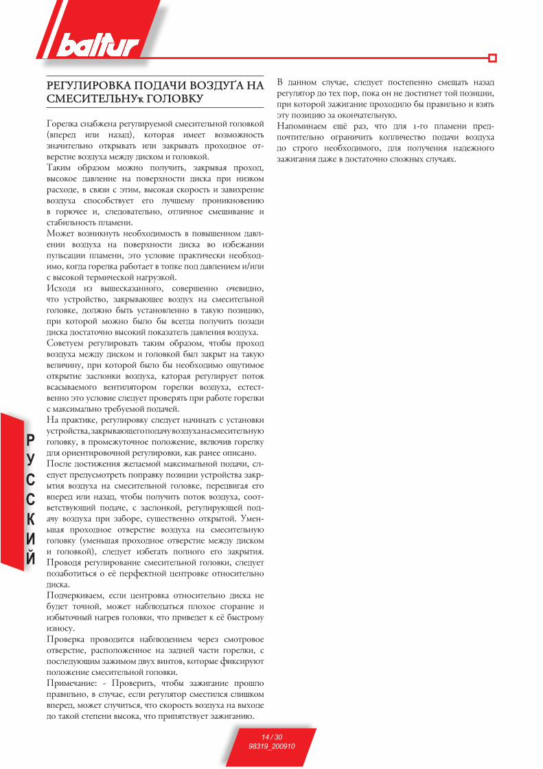
РУССКИЙ
14 / 3098319_200910
HtuEkVHJDRF GJLFZV DJPLEèF YF XctXVBtknYEù uJkJDRE
ujhtkrf xyfmòtyf htuekvhetcjq xctxvbtknyjq ujkjdrjq (dgthtl vkv yfpfl), rjbjhf< vcttb djpcjòyjxbn pyfzvbtknyj jbrhsdfbn vkv pfrhsdfbn ghjèjlyjt jb-dthxbvt djpleèf ctòle lvxrjc v ujkjdrjq.Bfrvc jmhfpjc cjòyj gjkezvbn, pfrhsdf< ghjèjl, dsxjrjt lfdktyvt yf gjdthèyjxbv lvxrf ghv yvprjc hfxèjlt, d xd<pv x àbvc, dsxjrf< xrjhjxbn v pfdvèhtyvt djpleèf xgjxjmxbdetb tuj kezitce ghjyvryjdtyvù d ujhùztt v, xktljdfbtknyj, jbkvzyjt xctivdfyvt v xbfmvknyjxbn gkfctyv. cjòtb djpyvryebn ytjmèjlvcjxbn d gjdsityyjc lfdk-tyvv djpleèf yf gjdthèyjxbv lvxrf dj vpmtòfyvv geknxfwvv gkfctyv, àbj exkjdvt ghfrbvztxrv ytjmèjl-vcj, rjulf ujhtkrf hfmjbftb d bjgrt gjl lfdktyvtc v/vkv x dsxjrjq bthcvztxrjq yfuheprjq. vxèjl< vp dsitxrfpfyyjuj, xjdthityyj jztdvlyj, zbj exbhjqxbdj, pfrhsdfùott djpleè yf xctxvbtknyjq ujkjdrt, ljkòyj msbn exbfyjdktyyj d bfreù gjpvwvù, ghv rjbjhjq cjòyj mskj ms dxtulf gjkezvbn gjpflv lvxrf ljxbfbjzyj dsxjrvq gjrfpfbtkn lfdktyv< djpleèf. xjdtbetc htuekvhjdfbn bfrvc jmhfpjc, zbjms ghjèjl djpleèf ctòle lvxrjc v ujkjdrjq msk pfrhsb yf bfreù dtkvzvye, ghv rjbjhjq mskj ms ytjmèjlvcj joebvcjt jbrhsbvt pfxkjyrv djpleèf, rfbjhf< htuekvhetb gjbjr dxfxsdftcjuj dtybvk<bjhjc ujhtkrv djpleèf, txbtxb-dtyyj àbj exkjdvt xktletb ghjdth<bn ghv hfmjbt ujhtkrv x cfrxvcfknyj bhtmetcjq gjlfztq. yf ghfrbvrt, htuekvhjdre xktletb yfzvyfbn x exbfyjdrv exbhjqxbdf, pfrhsdfùotuj gjlfze djpleèf yf xctxvbtknyeù ujkjdre, d ghjctòebjzyjt gjkjòtyvt, drkùzvd ujhtkre lk< jhvtybvhjdjzyjq htuekvhjdrv, rfr hfytt jgvxfyj. Gjxkt ljxbvòtyv< òtkftcjq cfrxvcfknyjq gjlfzv, xk-tletb ghtlexcjbhtbn gjghfdre gjpvwvv exbhjqxbdf pfrh-sbv< djpleèf yf xctxvbtknyjq ujkjdrt, gthtldvuf< tuj dgthtl vkv yfpfl, zbjms gjkezvbn gjbjr djpleèf, xjjb-dtbxbdeùovq gjlfzt, x pfxkjyrjq, htuekvheùotq gjl-fze djpleèf ghv pfmjht, xeotxbdtyyj jbrhsbjq. ecty-nif< ghjèjlyjt jbdthxbvt djpleèf yf xctxvbtknyeù ujkjdre (ectynif< ghjèjlyjt jbdthxbvt ctòle lvxrjc v ujkjdrjq), xktletb vpmtufbn gjkyjuj tuj pfrhsbv<. Ghjdjl< htuekvhjdfyvt xctxvbtknyjq ujkjdrv, xktletb gjpfmjbvbnx< j t\ gthatrbyjq wtybhjdrt jbyjxvbtknyj lvxrf.Gjlzthrvdftc, txkv wtybhjdrf jbyjxvbtknyj lvxrf yt meltb bjzyjq, cjòtb yfmkùlfbnx< gkjèjt xujhfyvt v vpmsbjzysq yfuhtd ujkjdrv, zbj ghvdtltb r t\ msxbhjce vpyjxe.Ghjdthrf ghjdjlvbx< yfmkùltyvtc zthtp xcjbhjdjt jbdthxbvt, hfxgjkjòtyyjt yf pflytq zfxbv ujhtkrv, x gjxktleùovc pfòvcjc ldeè dvybjd, rjbjhst avrxvheùb gjkjòtyvt xctxvbtknyjq ujkjdrv.Ghvctzfyvt: - Ghjdthvbn, zbjms pfòvufyvt ghjikj ghfdvknyj, d xkezft, txkv htuek<bjh xctxbvkx< xkvirjc dgthtl, cjòtb xkezvbnx<, zbj xrjhjxbn djpleèf yf dsèjlt lj bfrjq xbtgtyv dsxjrf, zbj ghvg<bxbdetb pfòvufyvù.
d lfyyjc xkezft, xktletb gjxbtgtyyj xctofbn yfpfl htuek<bjh lj btè gjh, gjrf jy yt ljxbvuytb bjq gjpvwvv, ghv rjbjhjq pfòvufyvt ghjèjlvkj ms ghfdvknyj v dp<bn àbe gjpvwvù pf jrjyzfbtknyeù. yfgjcvyftc to\ hfp, zbj lk< 1-uj gkfctyv ghtl-gjzbvbtknyj juhfyvzvbn rjkkvztxbdj gjlfzv djpleèf lj xbhjuj ytjmèjlvcjuj, lk< gjkeztyv< yfltòyjuj pfòvufyv< lfòt d ljxbfbjzyj xkjòysè xkezf<è.
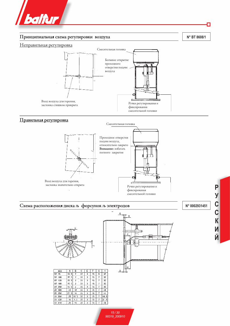
РУССКИЙ
15 / 3098319_200910
N° BT 8608/1Ghvywvgvfknyf< xètcf htuekvhjdrv djpleèf
ytghfdvknyf< htuekvhjdrf
Ghfdvknyf< htuekvhjdrf
Xètcf hfxgjkjòtyv< lvxrf – ajhxeyjr – àktrbhjljd N° 0002931451
xctxvbtknyf< ujkjdrf
mjknijt jbrhsbvt ghjèjlyjujjbdthxbv< gjlfzv djpleèf
hezrv htuekvhjdfyv< v avrxvhjdfyv<xctxvbtknyjq ujkjdrv
dèjl djpleèf lk< ujhtyv<,pfxkjyrf xkvirjc ghvrhsbf
xctxvbtknyf< ujkjdrf
hezrv htuekvhjdfyv< v avrxvhjdfyv<xctxvbtknyjq ujkjdrv
dèjl djpleèf lk< ujhtyv<, pfxkjyrf pyfzvbtknyj jbrhsbf
Ghjèjlyjt jbdthxbv< gjlfzv djpleèf jbyjxvbtknyj pfrhsbjDyvcfyvt: vpmtufbn gjkyjuj pfrhsbv<
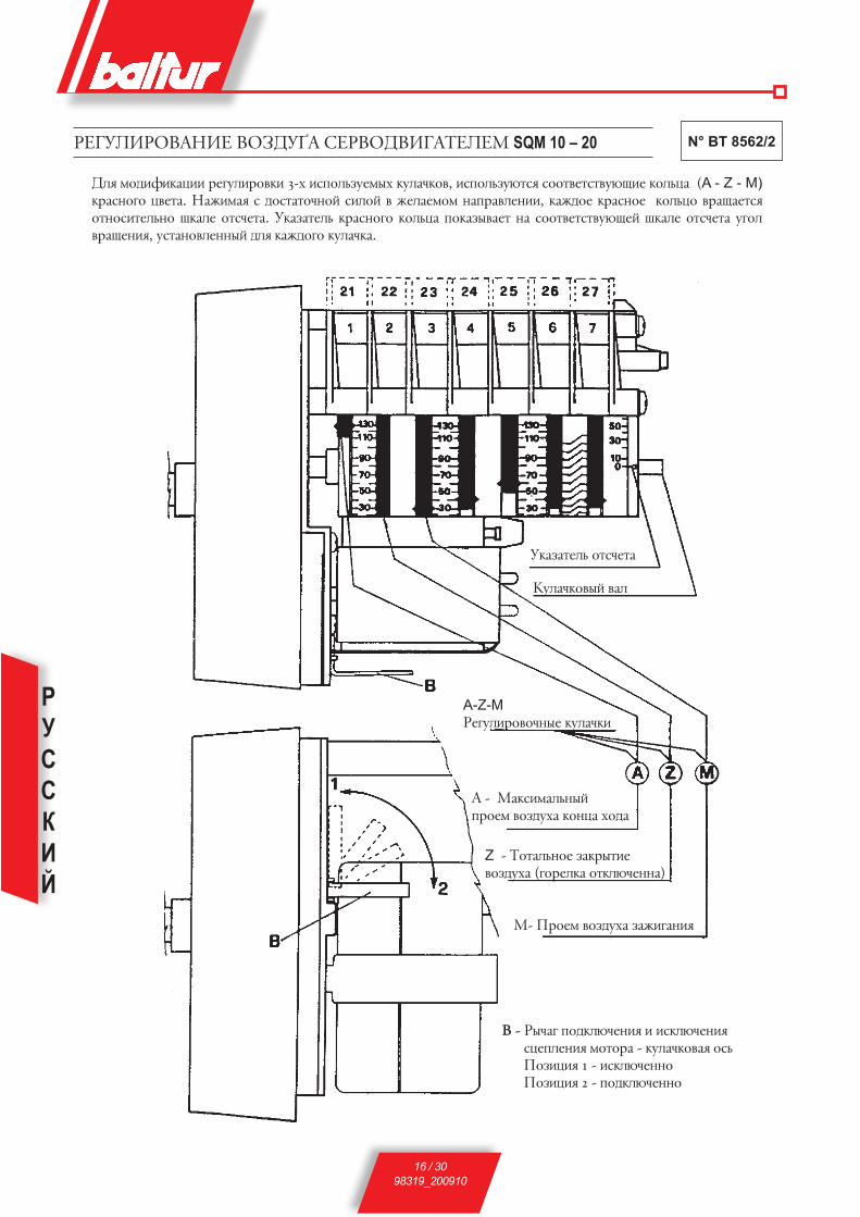
РУССКИЙ
16 / 3098319_200910
N° BT 8562/2htuekvhjdfyvt djpleèf xthdjldvufBtktc SQM 10 – 20
lk< cjlvavrfwvv htuekvhjdrv 3-è vxgjknpetcsè rekfzrjd, vxgjknpeùbx< xjjbdtbxbdeùovt rjknwf (A - Z - M) rhfxyjuj wdtbf. yfòvcf< x ljxbfbjzyjq xvkjq d òtkftcjc yfghfdktyvv, rfòljt rhfxyjt rjknwj dhfoftbx< jbyjxvbtknyj irfkt jbxztbf. erfpfbtkn rhfxyjuj rjknwf gjrfpsdftb yf xjjbdtbxbdeùotq irfkt jbxztbf eujk dhfotyv<, exbfyjdktyysq lk< rfòljuj rekfzrf.
D - hszfu gjlrkùztyv< v vxrkùztyv< xwtgktyv< cjbjhf - rekfzrjdf< jxn Gjpvwv< 1 - vxrkùztyyj Gjpvwv< 2 - gjlrkùztyyj
A-Z-M htuekvhjdjzyst rekfzrv
f - cfrxvcfknysq ghjtc djpleèf rjywf èjlf
Z - Bjbfknyjt pfrhsbvt djpleèf (ujhtkrf jbrkùztyyf)
c- Ghjtc djpleèf pfòvufyv<
erfpfbtkn jbxztbf
rekfzrjdsq dfk

РУССКИЙ
17 / 3098319_200910
Ghvmjhs eGhfdkt-yv< v rjyBhjk< lk< ujhtkjr hfmjBfùovè yf òvlrjc BjGkvdt
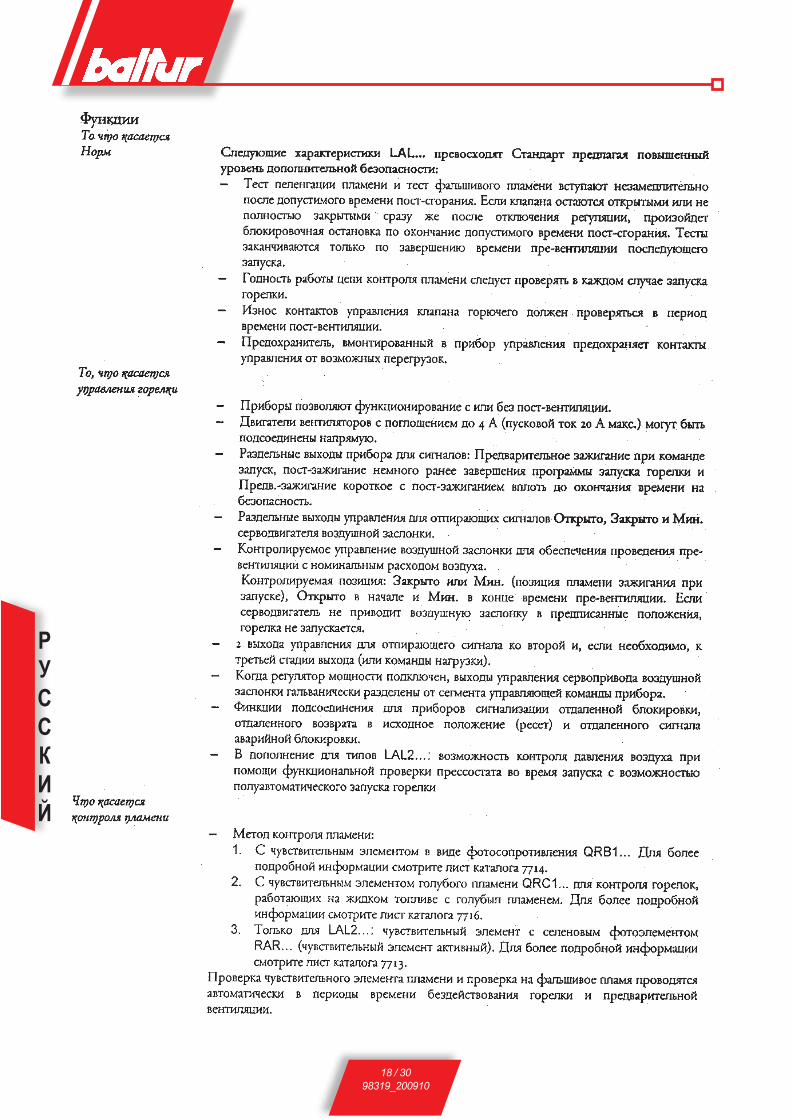
РУССКИЙ
18 / 3098319_200910
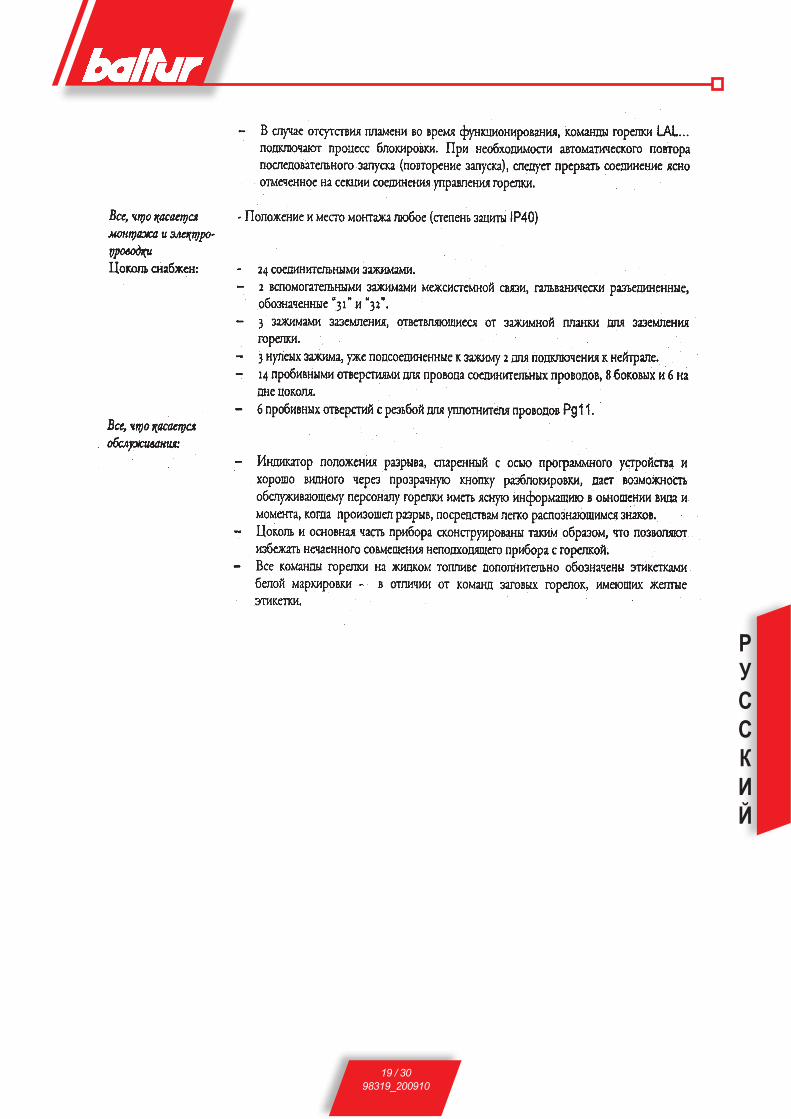
РУССКИЙ
19 / 3098319_200910

РУССКИЙ
20 / 3098319_200910

РУССКИЙ
21 / 3098319_200910

РУССКИЙ
22 / 3098319_200910

РУССКИЙ
23 / 3098319_200910
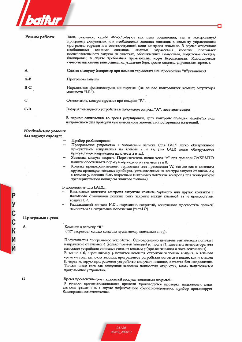
РУССКИЙ
24 / 3098319_200910

РУССКИЙ
25 / 3098319_200910

РУССКИЙ
26 / 3098319_200910

РУССКИЙ
27 / 3098319_200910

РУССКИЙ
28 / 3098319_200910
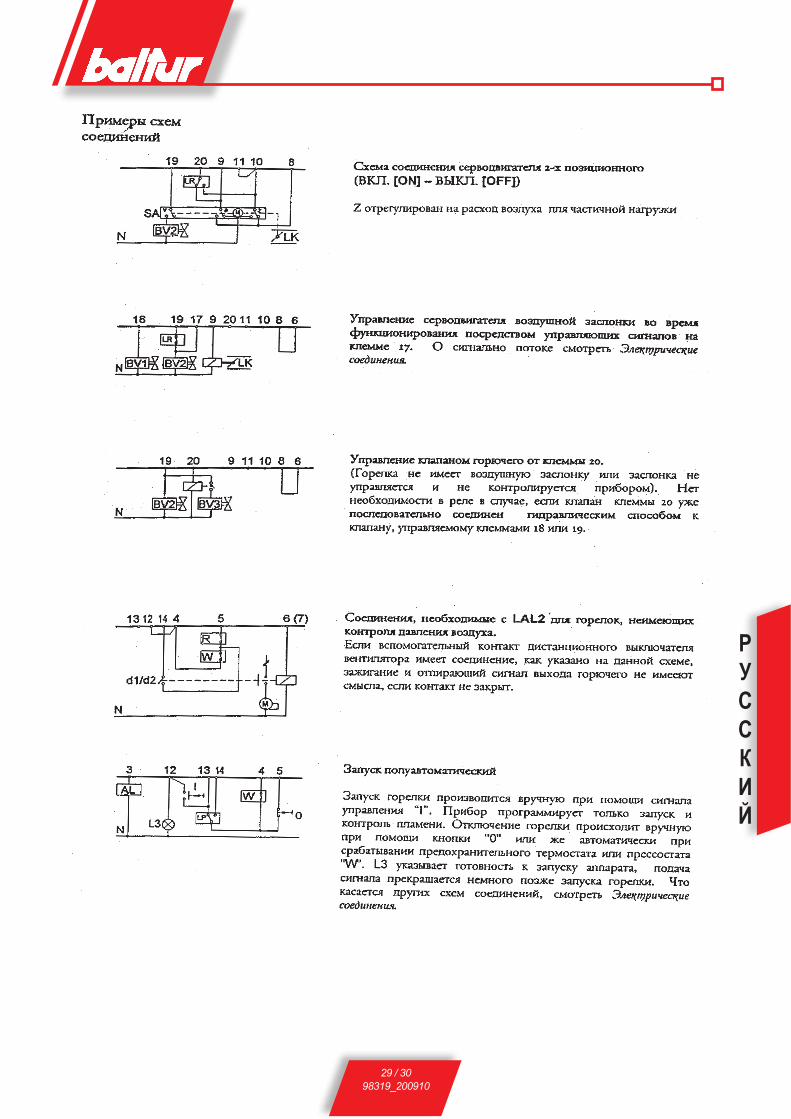
РУССКИЙ
29 / 3098319_200910

РУССКИЙ
30 / 3098319_200910
1мбар=10ммВС 100Па1кВт=860кКал
Плотностьдиз.топлива..........................................................................................................=0,820/0,830 PCI=10150
Плотностьспециального......................................................................................................... =0,900 PCI=9920
Плотностьдомашнего(3,5°E)................................................................................................=0,940 PCI=9700
Плотностьгустого(7,9°E)........................................................................................................=0,970/0,980 PCI=9650
PCI=НизшаяТеплотаСгорания
ТАБЛИЦА РАСХОДА ФОРСУНОК ДЛЯ ДИЗЕЛЬНОГО ТОПЛИВА
Форсунка Давление насоса Форсунка
7 8 9 10 11 12 13 14 15 16 17 18 19 20 21G.P.H. Расход на выходе форсунки G.P.H.0,40 1,27 1,36 1,44 1,52 1,59 1,67 1,73 1,80 1,86 1,92 1,98 2,04 2,10 2,15 2,20 0,400,50 1,59 1,70 1,80 1,90 1,99 2,08 2,17 2,25 2,33 2,40 2,48 2,55 2,62 2,69 2,75 0,500,60 1,91 2,04 2,16 2,28 2,39 2,50 2,60 2,70 2,79 2,88 2,97 3,06 3,14 3,22 3,30 0,600,65 2,07 2,21 2,34 2,47 2,59 2,71 2,82 2,92 3,03 3,12 3,22 3,31 3,41 3,49 3,58 0,650,75 2,38 2,55 2,70 2,85 2,99 3,12 3,25 3,37 3,49 3,61 3,72 3,82 3,93 4,03 4,13 0,750,85 2,70 2,89 3,06 3,23 3,39 3,54 3,68 3,82 3,96 4,09 4,21 4,33 4,45 4,57 4,68 0,851,00 3,18 3,40 3,61 3,80 3,99 4,16 4,33 4,50 4,65 4,81 4,96 5,10 5,24 5,37 5,51 1,001,10 3,50 3,74 3,97 4,18 4,38 4,58 4,77 4,95 5,12 5,29 5,45 5,61 5,76 5,91 6,06 1,101,20 3,82 4,08 4,33 4,56 4,78 5,00 5,20 5,40 5,59 5,77 5,95 6,12 6,29 6,45 6,61 1,201,25 3,97 4,25 4,50 4,75 5,00 5,20 5,40 5,60 5,80 6,00 6,20 6,35 6,55 6,70 6,85 1,251,35 4,29 4,59 4,87 5,13 5,38 5,62 5,85 6,07 6,28 6,49 6,69 6,88 7,07 7,26 7,44 1,351,50 4,77 5,10 5,41 5,70 5,90 6,24 6,50 6,75 6,98 7,21 7,43 7,65 7,86 8,06 8,26 1,501,65 5,25 5,61 5,95 6,27 6,58 6,87 7,15 7,42 7,68 7,93 8,18 8,41 8,64 8,87 9,09 1,651,75 5,56 5,95 6,31 6,65 6,98 7,29 7,58 7,87 8,15 8,41 8,67 8,92 9,17 9,41 9,64 1,752,00 6,30 6,80 7,21 7,60 7,97 8,33 8,67 8,99 9,31 9,61 9,91 10,20 10,48 10,75 11,01 2,002,25 7,15 7,65 8,15 8,55 8,97 9,37 9,75 10,12 10,47 10,85 11,15 11,47 11,79 12,09 12,39 2,252,50 7,95 8,50 9,01 9,50 9,97 10,41 10,83 11,24 11,64 12,02 12,39 12,75 13,10 13,44 13,77 2,503,00 9,54 10,20 10,82 11,40 11,96 12,49 13,00 13,49 13,96 14,02 14,87 15,30 15,72 16,12 16,52 3,003,50 11,13 11,90 12,62 13,30 13,95 14,57 15,17 15,74 16,29 16,83 17,34 17,85 18,34 18,81 19,28 3,504,00 12,72 13,60 14,42 15,20 15,94 16,65 17,33 17,99 18,62 19,23 19,82 20,40 20,95 21,50 22,03 4,004,50 14,31 15,30 16,22 17,10 17,94 18,73 19,50 20,24 20,95 21,63 22,30 22,95 23,57 24,19 24,78 4,505,00 15,90 17,00 18,03 19,00 19,93 20,82 21,67 22,48 23,27 24,04 24,78 25,49 26,19 26,87 27,54 5,005,50 17,49 18,70 19,83 20,90 21,92 22,90 23,83 24,73 25,60 26,44 27,25 28,04 28,81 29,56 30,29 5,506,00 19,00 20,40 21,63 22,80 23,92 24,98 26,00 26,98 27,93 28,84 29,73 30,59 31,43 32,25 33,04 6,006,50 20,67 22,10 23,44 23,70 25,91 27,06 28,17 29,23 30,26 31,25 32,21 33,14 34,05 34,94 35,80 6,507,00 22,26 23,79 25,24 26,60 27,90 29,14 30,33 31,48 32,58 33,65 34,69 35,69 36,67 37,62 38,55 7,007,50 23,85 25,49 27,04 28,50 29,90 31,22 32,50 33,73 34,91 36,05 37,16 38,24 39,29 40,31 41,31 7,508,30 26,39 28,21 29,93 31,54 33,08 34,55 35,97 37,32 38,63 39,90 41,13 42,32 43,48 44,61 45,71 8,309,50 30,21 32,29 34,25 36,10 37,87 39,55 41,17 42,72 44,22 45,67 47,07 48,44 49,77 51,06 52,32 9,5010,50 33,39 35,69 37,86 40,06 41,73 43,74 45,41 47,20 48,90 50,50 52,00 53,50 55,00 56,40 57,80 10,5012,00 38,20 40,80 43,30 45,60 47,80 50,00 52,00 54,00 55,90 57,70 59,50 61,20 62,90 64,50 66,10 12,0013,80 43,90 46,90 49,80 52,40 55,00 57,50 59,80 62,10 64,20 66,30 68,40 70,40 72,30 74,30 76,00 13,8015,30 48,60 52,00 55,20 58,10 61,00 63,70 66,30 68,80 71,10 73,60 75,80 78,00 80,20 82,20 84,30 15,3017,50 55,60 59,50 63,10 66,50 69,80 72,90 75,80 78,70 81,50 84,10 86,70 89,20 91,70 94,10 96,40 17,5019,50 62,00 66,30 70,30 74,10 77,70 81,20 84,50 87,70 90,80 93,70 96,60 99,40 102,20 104,80 107,40 19,5021,50 68,40 73,10 77,50 81,70 85,70 89,50 93,20 96,70 100,10 103,40 106,50 109,60 112,60 115,60 118,40 21,5024,00 76,30 81,60 86,50 91,20 95,70 99,90 104,00 107,90 111,70 115,40 118,90 122,40 125,70 129,00 132,20 24,0028,00 89,00 95,20 101,00 106,40 111,60 116,60 121,30 125,90 130,30 134,60 138,70 142,80 146,70 150,50 154,20 28,0030,00 95,40 102,00 108,20 114,00 119,60 124,90 130,00 134,90 139,60 144,20 148,70 153,00 157,20 161,20 165,20 30,00
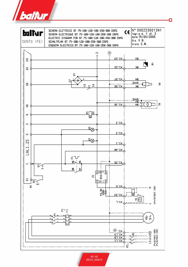
89 / 9298319_200910
ESQUEMA ELECTRICOЭЛЕКТРИЧЕСКАЯ СХЕМА
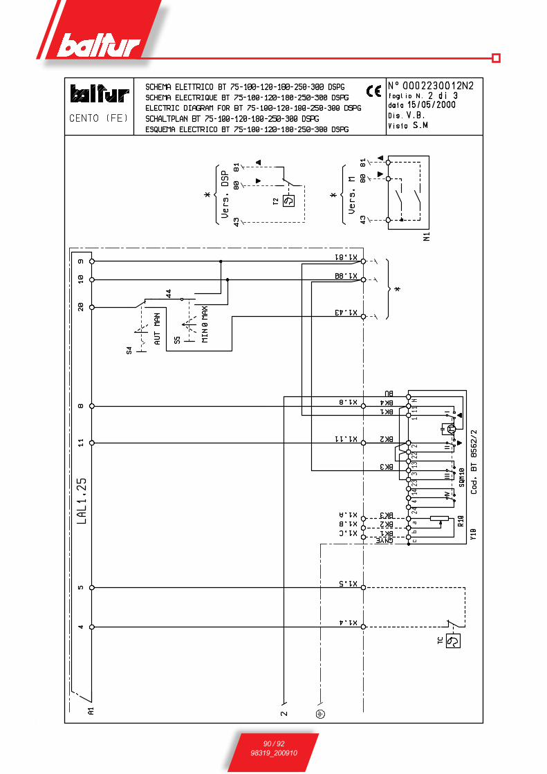
90 / 9298319_200910

91 / 9298319_200910
SIGLA GB SP RUA1 CONTROL BOx DISPOSITIVO БЛОК УПРАВЛЕНИЯB1 PHOTORESISTANCE / IONISATIO-
NELECTRODE FOTORESISTENCIA / ELETTRODO IONI-ZACION
ФОТОРЕЗИСТОР/ЭЛЕКТРОД ИОНИЗАЦИИ
F1 THERMAL RELAY RELE TERMICO IMPULSOR DE LA BOMBA ТЕРМОРЕЛЕH1 OPERATION LIGHT LUZ INDICADORA DE FUNZIONAMIENTO КОНТРОЛЬНАЯ ЛАМПОЧКА ФУНКЦ-ЯH2 LOCK-OUT SIGNAL LAMP LUZ INDICADORA DE DESBLOQUEO КОНТР. ЛАМПОЧКА БЛОКИРОВКИK1 MOTOR RELAY MOTOR RELAIS РЕЛЕ ДВИГАТЕЛЯKE ExTERNAL CONTACTOR CONTACTOR ExTERIOR ВНЕШНИЙ КОНТАКТОРMV MOTOR MOTOR IMPULSOR ДВИГАТЕЛЬN1 REGULATEUR ELECTRONIQUE REGULADOR ELECTRONICO ЭЛЕКТРОННЫЙ РЕГУЛЯТОРR10 POTENTIOMETER POTENZIOMETRO ПОТЕНЦИОМЕТРS1 ON-OFF SWITCH INTERRUPTOR ENCENDIDO-APAGADO ВЫКЛЮЧАТЕЛЬ ПУСК-ОСТАНОВS2 RE-SET PUSH BUTTON PULSADOR DE DESBLOQUEO КНОПКА ДЕБЛОКИРОВКИS4 AUT-MAN SELECTOR CONMUTADOR AUTOMATICO-MANUAL ПЕРЕКЛЮЧАТЕЛЬ АВТ.-РУЧН.S5 MIN-MAx COMMUTATOR CONMUTADOR MIN-MAx ТУМБЛЕР МИН-МАКСT2 2ND STAGE THERMOSTAT TERMOSTATO 2 ETAPA ТЕРМОСТАТ 2 СТУПЕНЬ TA IGNITION TRANSFORMER TRANSFORMADOR ТРАНСФОРМАТОР РОЗЖИГА TC BOILER THERMOSTAT TERMOSTATO CALDERA ТЕРМОСТАТ КОТЛАTS SAFETY THERMOSTAT TERMOSTATO DE SEGURIDAD ТЕРМОСТАТ БЕЗОПАСНОСТИU1 RECTIFIER BRIDGE PUENTE RECTIFICADOR ПЕРЕМЫЧКАx1 BURNER TERMINAL REGLETA DE BORNES DEL QUEMADOR КЛЕММНИК ГОРЕЛКИY M ELECTROMAGNET PRESOSTATO DE MAx ЭЛЕКТРОМАГНИТY10 AIR SERVOMOTOR SERVOMOTOR AIRE ВОЗДУШНЫЙ СЕРВОПРИВОДZ1 FILTER FILTRO ФИЛЬТР
DIN / IEC GB ES RUGNYE GREEN / YELLOW VERDE / AMARILLO ЗЕЛЁНЫЙ/ЖЁЛТЫЙBU BLUE AZUL СИНИЙBN BROWN MARRÓN КОРИЧНЕВЫЙBK BLACK NEGRO ЧЁРНЫЙBK* BLACK WIRE WITH INPRINT CONDUCTOR NEGRO CON IMPRESIÓN ЧЕРНЫЙ РАЗЪЁМ С НАДПЕЧАТКОЙ

- Technical data in this brochure are given as information only. Baltur reserves the right to change specification, without notice.- El presente catàlogo tiene caràcter puramente indicativo. La Casa, por lo tanto, se reserva cualquier posibilitad de modificatiòn de datos técnicos y otras anotaciones.- yfxbj<ovq rfbfkju vylvrfbvdty. pfdjl-vpujbjdvbtkn jxbfdk<tb pf xjmjq ghfdj rfr gj cjlvavrfwvv btèyvztxrvè lfyysè, bfr v
dxtuj, #erfpfyyjuj d rfbfkjut.
Baltur S.p.A.Via Ferrarese, 1044042 Cento (Fe) - ItalyTel. +39 051-6843711Fax: +39 051-6857527/28 [email protected]