Embed Size (px)
Citation preview

Bubble‐Up® Jr Interactive™ Manual
Installation and Operating Instructions Bubble-Up® Jr Interactive™ Radon Removal System
U.S. Patent # 6,372,024, Item No. 86302
Manufactured by: R.E Prescott Co., Inc.
10 Railroad Avenue • Exeter, New Hampshire • 03833 Phone: (603) 772‐4321 • Fax: (603) 772‐1089
REPRESCOTT.COM

Bubble‐Up® Jr Interactive™ Radon Removal System
2
The Bubble‐Up® Interactive unit from R.E. Prescott Co., Inc. is designed to remove radon gas from water. Radon is a radioactive gas which can cause serious health problems. Inside the unit, air is blown into the incoming water and allowed to bubble upward. This bubbling action releases the radon from the water. Air containing the radon is then collected and vented out. Specifications Dimensions: Depth: 18” Width: 24” Tank Height: 41” Overall Height: 60”
Maximum water depth: 26” (off float switch level) Refill water depth: 19” (on float switch level) Run dry water depth: 5”
Cycle Tank: 2.1 Gallon, 3/4” MNPT, 8” Diameter X 10” Tall, Water Expansion Tank
Water capacity: On/Off Cycle Volume: 7 Gallons Usable water at maximum water depth of 26”: 34 Gallons Usable water at refill water depth of 19”: 27 Gallons
Approximate weight: 90 lb. empty 373 lb. filled to maximum water depth of 26” 507 lb. filled to overflow water depth of 41” Plumbing connections: 1” male npt water inlet and outlet bypass valve
2” fnpt air inlet with nipple for directly mounting Bubble‐Up® Jr Interactive™ blower 2” male PVC socket weld air outlet 1.25” fnpt overflow connection 3/4" Male npt for expansion tank
Electrical: Dedicated 20A circuit, Quadplex outlet, 115V AC #12 AWG wiring Pump: 1/2 HP high pressure (75 p.s.i.) submersible pump
10.6 A maximum (running) @ 115V
Blower: 4.5A, 115V AC Solenoid valve: 7 GPM Standard, 1/2” fnpt, CV = 2.0, 115V coil for 7 gpm, or 14 GPM Adder, 3/4" fnpt, CV = 5.0, 115V coil for 14 GPM Motorized Ball Valve: 7 GPM, 1/2" Standard or 14 GPM, 3/4" Adder Pump controller: Bubble‐Up Mechanical Pump Control, 7 GPM Standard or 14 GPM Adder, protects the pump
from running dry, integral check valve, and operates the pump from a 2.1 gallon tank, 115V AC Radon removal efficiency: Inlet Flow and Pressure Specifications
MODEL GPM EFFICIENCY
Bubble‐Up® Jr Interactive™ 7 GPM Standard, 1/2” Solenoid
7 99%
Bubble‐Up® Jr Interactive™ 14 GPM Adder, 3/4" Solenoid
14 98%

Bubble‐Up® Jr Interactive™ Radon Removal System
3
0000 Figure 1 ‐ Bubble‐Up® Jr Interactive™ Inlet Pressure vs. Flow
Outlet Flow and Pressure Specifications
00 Figure 2 ‐ Bubble‐Up® Jr Interactive™ Outlet Flow vs. Pressure 7 GPM
7 GPM Pump Control w/ 1/2” Pex
7 GPM Standard
14 GPM Adder
Mechanical Pump Control copy
7 GPM Standard Mechanical Pump Control
Pressure vs. Flow

Bubble‐Up® Jr Interactive™ Radon Removal System
4
00 Figure 3 – Bubble‐Up® Jr Interactive™ Outlet Flow vs. Pressure 14 GPM
Figure 4 – Radon Removal vs. Flow
14 GPM Pump Control w/ 3/4” Pex
Mechanical Pump Control14 copy
14 GPM Adder Mechanical Pump Control
Pressure vs. Flow

Bubble‐Up® Jr Interactive™ Radon Removal System
5
Controls and Indicators Bypass valve This valve can be used to divert the water flow if a problem develops with Bubble‐Up® Jr Interactive™ unit. This valve has two red handles, and is located near the back of the unit. See Figure 8. The valve has two positions:
• Service ‐ This is the normal operating position. When the two valve handles are in line with water flow, the unit can remove radon from the incoming water.
• Bypass ‐ When the two valve handles are perpendicular to water flow, the incoming water “bypasses” Bubble‐Up® Jr Interactive™ unit. Use this position only if there is a problem with the unit.
Caution! When the bypass valves are set to the Bypass position, Bubble‐Up® Jr Interactive™ unit cannot provide any protection against radon in the water.
Meter Control For instructions regarding the meter control refer to the Bubble‐Up Meter Control manual supplied with Bubble‐Up® Jr Interactive™ and online at www.represcott.com Mechanical Pump Control For instructions regarding the mechanical pump control see Bubble‐Up Mechanical Pump Control Assembly Owner’s Manual supplied with Bubble‐Up® Jr Interactive™ and online at www.represcott.com. Water Alarm Valve The water alarm valve is designed to identify leaking problems in the Bubble‐Up® Jr Interactive™. It is designed to monitor radon vent obstruction, high water and fitting leaks. It does this by incorporating a water alarm valve float switch and terminal block to signal the water alarm valve control which operates the motorized water alarm ball valve. See figure 16 and 17. Important Feature: The water alarm valve can also be used to create any number of remote leak detection points by connecting
extra leads to the leads of the terminal block. Users Guide:
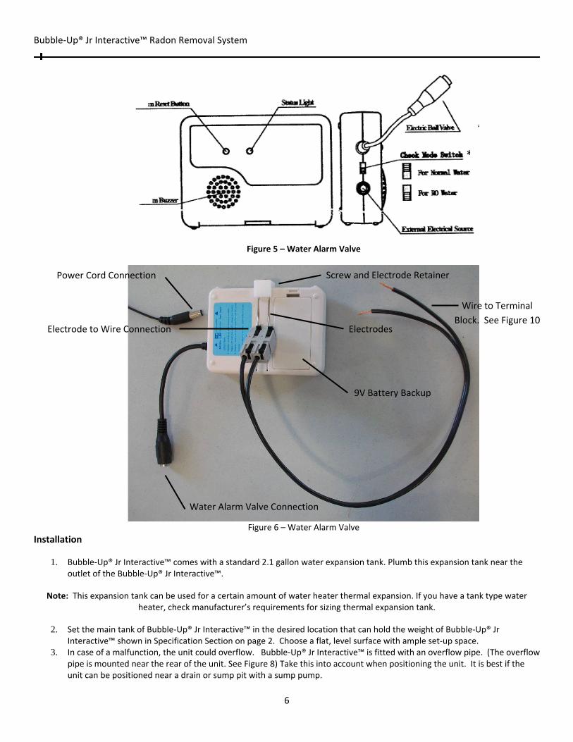
Please choose the correct mode on the mode switch shown in the picture according to the application. In the case of the Bubble‐Up® Jr Interactive™, the switch should be in the normal water position. See figure 5*
The buzzer will beep if there is a radon vent pipe obstruction, high water alarm or detected water leak, and at the same time a signal will be sent to the external electric ball valve. This signal will cause the ball valve to close and cut off the water supply immediately.
To reset the electric ball valve to its original open position, hold the reset button for three seconds.
A yellow light accompanied by the buzzer means that the battery is low. If this occurs replace the battery as soon as possible to avoid any overflows during a power outage. Important information about the Water Alarm Valve: The alarm on this control will go off if there is water inside of the
control. If this occurs, fully dry the inside of the control before returning it to service.
Bubble‐Up® Jr Interactive™ Radon Removal System
6
Figure 5 – Water Alarm Valve
Figure 6 – Water Alarm Valve
Installation
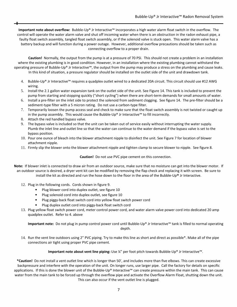
1. Bubble‐Up® Jr Interactive™ comes with a standard 2.1 gallon water expansion tank. Plumb this expansion tank near the outlet of the Bubble‐Up® Jr Interactive™.
Note: This expansion tank can be used for a certain amount of water heater thermal expansion. If you have a tank type water heater, check manufacturer’s requirements for sizing thermal expansion tank.
2. Set the main tank of Bubble‐Up® Jr Interactive™ in the desired location that can hold the weight of Bubble‐Up® Jr
Interactive™ shown in Specification Section on page 2. Choose a flat, level surface with ample set‐up space. 3. In case of a malfunction, the unit could overflow. Bubble‐Up® Jr Interactive™ is fitted with an overflow pipe. (The overflow
pipe is mounted near the rear of the unit. See Figure 8) Take this into account when positioning the unit. It is best if the unit can be positioned near a drain or sump pit with a sump pump.
Power Cord Connection Screw and Electrode Retainer
Electrodes
Wire to Terminal
Block. See Figure 10
9V Battery Backup
Electrode to Wire Connection
Water Alarm Valve Connection
*
Bubble‐Up® Jr Interactive™ Radon Removal System
7
Important note about overflow: Bubble‐Up® Jr Interactive™ incorporates a high water alarm float switch in the overflow. The control will operate the water alarm valve and shut off incoming water when there is an obstruction in the radon exhaust pipe, a faulty float switch assembly, tangled float switch assembly, or if the solenoid valve is stuck open. This water alarm valve has a battery backup and will function during a power outage. However, additional overflow precautions should be taken such as
connecting overflow to a proper drain.
Caution! Normally, the output from the pump is at a pressure of 70 PSI. This should not create a problem in an installation where the existing plumbing is in good condition. However, in an installation where the existing plumbing cannot withstand the
operating pressure of Bubble‐Up® Jr Interactive™, the output from the pump may produce a stress on the plumbing and cause leaks. In this kind of situation, a pressure regulator should be installed on the outlet side of the unit and drawdown tank.
4. Bubble‐Up® Jr Interactive™ requires a quadplex outlet wired to a dedicated 20A circuit. This circuit should use #12 AWG
wiring. 5. Install the 2.1 gallon water expansion tank on the outlet side of the unit. See Figure 14. This tank is included to prevent the
pump from starting and stopping quickly (“short cycling”) when there are short‐term demands for small amounts of water. 6. Install a pre‐filter on the inlet side to protect the solenoid from sediment clogging. See figure 14. The pre‐filter should be a
sediment‐type filter with a 5 micron rating. Do not use a carbon‐type filter. 7. Temporarily loosen the pump access seal and check to make sure that the float switch assembly is not twisted or caught up
in the pump assembly. This would cause the Bubble‐Up® Jr Interactive™ to fill incorrectly. 8. Attach the red handled bypass valve. 9. The bypass valve is included so that the unit can be taken out of service easily without interrupting the water supply.
Plumb the inlet line and outlet line so that the water can continue to the water demand if the bypass valve is set to the bypass position.
10. Pour one ounce of bleach into the blower attachment nipple to disinfect the unit. See Figure 7 for location of blower attachment nipple.
11. Firmly slip the blower onto the blower attachment nipple and tighten clamp to secure blower to nipple. See figure 8.
Caution! Do not use PVC pipe cement on this connection.
Note: If blower inlet is connected to draw air from an outdoor source, make sure that no moisture can get into the blower motor. If an outdoor source is desired, a dryer vent kit can be modified by removing the flap check and replacing it with screen. Be sure to
install the kit as directed and run the hose down to the floor in the area of the Bubble‐Up® Jr Interactive.
12. Plug in the following cords. Cords shown in figure 9. • Plug blower cord into duplex outlet, see figure 10 • Plug solenoid cord into duplex outlet, see figure 10 • Plug piggy‐back float switch cord into yellow float switch power cord
• Plug duplex outlet cord into piggy‐back float switch cord 13. Plug yellow float switch power cord, meter control power cord, and water alarm valve power cord into dedicated 20 amp
quadplex outlet. Refer to 4. above
Important note: Do not plug in pump control power cord until Bubble‐Up® Jr Interactive™ tank is filled to normal operating depth.
14. Run the vent line outdoors using 2” PVC piping. Try to make this line as short and direct as possible*. Make all of the pipe
connections air tight using proper PVC pipe cement.
Important note about vent line piping: Use ¼” per foot pitch towards Bubble‐Up® Jr Interactive™.
*Caution! Do not install a vent outlet line which is longer than 50’, and includes more than five elbows. This can create excessive backpressure and interfere with the operation of the unit. On longer runs, use larger pipe. Call the factory for details on specific
applications. If this is done the blower unit of the Bubble‐Up® Interactive™ can create pressure within the main tank. This can cause water from the main tank to be forced up through the overflow pipe and activate the Overflow Alarm Float, shutting down the unit.
This can also occur if the vent outlet line is plugged.

Bubble‐Up® Jr Interactive™ Radon Removal System
8
Caution! Do not install the vent opening at a location where the vent gasses could be blown back into an occupied space.
Important information about venting: Since the Bubble‐Up® Jr Interactive™ unit removes radon in the water, the unit must be vented carefully. Common practice is to run the vent up past the roof line of the building. An elevated vent
opening provides the best way of dissipating the radon gas. Protocols recommend extending the vent opening 2’ above the highest opening in the building, and at least 10’ away from the nearest opening. It is recommended to protect the vent opening with a vent screen. A single free hard (printed) copy of the ASTM E‐2121 standard (Recommended Residential Radon Mitigation Standard of Practice) is available from EPA’s National Service Center for Environmental Publications (NSCEP). You can order a copy by phone at 1‐800‐490‐9198, via E‐mail nscep@bps‐lmit.com, or via the internet at
www.epa.gov/nscep/ordering.htm Please use the EPA document number (402‐K‐03‐007) when ordering E‐2121. EPA reprints E‐2121 under agreement with ASTM International.
15. Plumb mechanical pump control and plug pump cord into female cord of pump control. 16. Check all plumbing fittings to be sure all fittings are water tight. 17. The water alarm valve control is wired to the power supply, motorized ball valve, and terminal block. 18. Install 9V battery backup into water alarm control. 19. Terminal block wires are for high water alarm valve control. These wires are twisted together black to white and connected
to terminal block. See figure 11 notes. Note: Electrode Terminal Block Connections: Check to be sure to strip insulation 1/2" from the end and tightly twist black wires to white wires. Connect one black and white wire twisted to each other to the black connection of the terminal block and the other twisted black and white wires to the red connection of the terminal block. Each connection of the terminal block should have one
black wire and one white wire connected to it. It is very important that this is a good connection.
20. Figure 10 & 11 show correct wiring to terminal block
Figure 7 ‐ Installation Points
Air Water Coupling
Pump Access Seal
Main Water Tank
Bubble‐Up Blower
Mechanical Pump Control
House Pressure Gauge
Blower Attachment
Nipple

Bubble‐Up® Jr Interactive™ Radon Removal System
9
Figure 8 ‐ Installation Points
Figure 9 ‐ Power Cords
Vent Outlet
Water Inlet and Outlet (Bypass Valve)
Overflow Pipe Remove 1 1/4” Plug
Mechanical Pump
Control Pressure Switch
Blower Attachment
Clamp
Water Alarm Valve
Cord
Yellow Float Switch Cord
Meter Control Cord
Black Pump Control
Cord
Piggy‐Back Float Switch Cord
Duplex Outlet Cord
Back Side of
Duplex Outlet

Bubble‐Up® Jr Interactive™ Radon Removal System
10
Figure 10 – Terminal Block and Overflow
Figure 11 – Overflow Alarm Float Assembly
Figure 11 Notes: Electrode Terminal Block Connections: Check to be sure to strip insulation 1/2" from the end and tightly twist black wires to white wires. Connect one black and white wire twisted to each other to the black connection of the terminal block and the other twisted black and white wires to the red connection of the terminal block. Each connection of the terminal block
should have one black wire and one white wire connected to it. It is very important that this is a good connection.
Overflow Alarm Float Cords
Overflow Alarm Float
Wire to Terminal
Block
Duplex Outlet
SS Breather Vent Terminal Block
Vent Outlet

Bubble‐Up® Jr Interactive™ Radon Removal System
11
Start Up Procedure
1. Set the red handles on the bypass valve to the Service position. 2. Before plugging in Bubble‐Up® Jr Interactive™, identify the plug‐in cords. See figure 9. 3. Plug in the meter control and water alarm valve control power cords. 4. Push reset button on water alarm valve control for 3 seconds to open the motorized ball valve. 5. Plug in the yellow cord first. The blower should start, and the solenoid valve should open to begin filling the tank.
Caution! Do not plug in the black cord for the mechanical pump control until the tank is filled with water. This will prevent
the pump from running while dry.
6. As the water level in the tank rises, the float switch will tilt up. This will stop the blower and close the solenoid valves. 7. Once the tank is full, plug in the black pump control cord.
Note: The pump control will require a manual start. Move pressure switch manual start lever to the start position until the pump
starts. See figure 15 or Bubble‐Up Mechanical Pump Control Owner’s Manual included with Bubble‐Up® Jr Interactive™.
8. If the pump does not start delivering water to the house, it may be necessary to prime the pump. (Normally you will only have to do this once, when the unit is first installed.) The pump is suspended by a pipe underneath the pump control. Unscrew the union and move the pump control off to the side. You may need to siphon or vacuum the water up this pipe to remove the air from the pump and prime it.
9. Once the air has been removed from the pump, replace the pump control and tighten the union. Plug in the pump. Move the lever on the Pressure Switch again to start the pump. If the pump does not start delivering water to the house, repeat the priming sequence.
10. After the unit is operating, run a radon test of the raw water and the filtered water to ensure that the unit is reducing radon levels in the water.
11. Perform the six‐month maintenance procedure, and fill out the Start‐Up Data page at the end of this manual.
Operating Instructions Once the Bubble‐Up® Jr Interactive™ has been installed, it should operate with very little attention. Normal Operation Main Unit The unit should not need any operator attention. When water is used in the house, the 2.1 gallon water expansion tank delivers water demand. When the pressure drops to the set pressure, the mechanical pump control starts Bubble‐Up® Jr Interactive™ pump to deliver water to the home and refill the 2.1 gallon water expansion tank. When the mechanical pump control senses normal household pressure, the mechanical pump control shuts the Bubble‐Up® Jr Interactive™ pump off. As the water level falls in Bubble‐Up® Jr Interactive™ main tank, the float switch powers the blower and solenoid to fill the main Bubble‐Up® Jr Interactive™ tank with treated water. Water Alarm Valve The water alarm valve is in place for protection against leaking or overflowing and will not operate unless one of these things happens. Once the water alarm valve control, overflow alarm float or terminal block senses a problem in the system the water alarm valve control activates the motorized ball valve and shuts off the incoming water. The water alarm valve control will also sound an alarm to identify that there is a problem. Bypassing the Unit If a problem develops, Bubble‐Up® Jr Interactive™ unit can be taken out of the water supply system with the bypass valve. The rest of the water system will operate normally, but Bubble‐Up® Jr Interactive™ will not be able to provide any protection against radon in the water.
Caution! Do not continue to operate the water supply system this way for a long time. Correct the problem with Bubble‐Up® Jr Interactive™ and return it to service as quickly as possible.
Bubble‐Up® Jr Interactive™ Radon Removal System
12
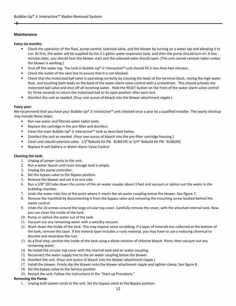
Maintenance Every six months:
• Check the operation of the float, pump control, solenoid valve, and the blower by turning on a water tap and allowing it to run. At first, the water will be supplied by the 2.1 gallon water expansion tank, and then the pump should turn on. A few minutes later, you should hear the blower start and the solenoid valve should open. (The unit cannot remove radon unless the blower is working.)
• Shut off the water tap. The tank in Bubble‐Up® Jr Interactive™ unit should fill in less than two minutes.
• Check the outlet of the vent line to ensure that it is not blocked. • Check that the motorized ball valve is operating correctly by crossing the leads of the terminal block, raising the high water
float, and touching both leads on the back of the water alarm valve control with a screwdriver. This should activate the motorized ball valve and shut off all incoming water. Hold the RESET button on the front of the water alarm valve control for three seconds to return the motorized ball to its open position after each test.
• Disinfect the unit as needed. (Pour one ounce of bleach into the blower attachment nipple.)
Every year: We recommend that you have your Bubble‐Up® Jr Interactive™ unit checked once a year by a qualified installer. The yearly checkup may include these steps:
• Run raw water and filtered water radon tests. • Replace the cartridge in the pre-filter and disinfect. • Clean the main Bubble‐Up® Jr Interactive™ tank as described below. • Disinfect the unit as needed. (Pour one ounce of bleach into the pre‐filter cartridge housing.) • Clean and rebuild solenoid valve. 1/2"Rebuild Kit PN: BUB019C or 3/4" Rebuild Kit PN: BUB020C
• Replace 9‐volt battery in Water Alarm Valve Control
Cleaning the tank: 1. Unplug all power cords to the unit. 2. Run a water faucet until main storage tank is empty. 3. Unplug the pump controller. 4. Set the bypass valve to the Bypass position. 5. Remove the blower and set it to one side. 6. Run a 3/8” OD tube down the center of the air‐water coupler about 3 feet and vacuum or siphon out the water in the
bubbling chamber. 7. Undo the water inlet line at the point where it meets the air‐water coupling below the blower. See figure 7. 8. Remove the manifold by disconnecting it from the bypass valve and removing the mounting screw located behind the
meter control. 9. Undo the 16 screws around the large circular top cover. Carefully remove the cover, with the attached internal tank. Now
you can clean the inside of the tank. 10. Pump or siphon the water out of the tank. 11. Vacuum out any remaining water with a wet/dry vacuum. 12. Wash down the inside of the tank. This may require some scrubbing. If a layer of minerals has collected at the bottom of
the tank, remove this layer. If the mineral layer includes a rusty material, you may have to use a reducing chemical to dissolve and neutralize the rust.
13. As a final step, sanitize the inside of the tank using a dilute solution of chlorine bleach. Rinse, then vacuum out any remaining water.
14. Re‐install the circular top cover with the internal tank and air‐water coupling. 15. Reconnect the water supply line to the air‐water coupling below the blower. 16. Disinfect the unit. (Pour one ounce of bleach into the blower attachment nipple.) 17. Install the blower. Firmly slip the blower onto the blower attachment nipple and tighten clamp. See figure 8. 18. Set the bypass valve to the Service position 19. Restart the unit. Follow the instructions in the “Start up Procedure.”
Removing the Pump: 1. Unplug both power cords to the unit. Set the bypass valve to the Bypass position.

Bubble‐Up® Jr Interactive™ Radon Removal System
13
2. Remove piping on top of mechanical pump control and unscrew 1” union located under the mechanical pump control. 3. Unplug and remove the pump control. 4. Unplug the piggy back float switch cord from the circuit box on Bubble‐Up® Jr Interactive™. 5. Loosen the 4 nuts on the pump access seal. See figure 7. Do not remove the top nuts so that the bolts do not fall into
Bubble‐Up® Jr Interactive™ main water tank. Note that the direction of the float switch cord is towards the air‐water coupling so that it can be re‐installed in the same position.
6. Lift the pump access seal off of the main water tank. This may require prying with a flat screwdriver or two. 7. Lift and pull out float switch and then pump from the main water tank.
Troubleshooting for Bubble‐Up Mechanical Pump Controller Low‐Water Failure Re‐Start A low pressure cut‐out switch is used to turn off the pump during low pressure or low water. This can occur due to a solenoid, well pump, or water alarm valve. If the water alarm valve or solenoid is stuck closed, incoming water will not be allowed to enter the Bubble‐Up® Jr Interactive™ main tank. This will cause the tank to empty and the pump to run dry. If the well pump fails there will be no water entering the main tank of the Bubble‐Up® Jr Interactive™ also causing the pump to run dry and shut off due to low‐water failure. On flows greater than 10 GPM and over 14 GPM for 14 GPM units, low pressure may occur and also turn off the pump. To re‐start the pump from this condition move the lever on the pressure switch to start and hold the lever until the pump builds sufficient pressure to keep the pressure switch contacts closed. If the pump does not build up pressure, reduce water flow or check the water level in the Bubble‐Up tank. Be sure pump is in good working order and is not air bound. (See Bubble‐Up Mechanical Pump Control) High‐Water Alarm Three things can cause the high‐water alarm valve control to sound:
The leak detection terminal block is wet, repair leak and dry off the top of the Bubble‐Up® Jr Interactive™.
Vent line is obstructed, forcing the water up the overflow and triggering the high water alarm float switch. Clear obstruction.
High water alarm float is triggered due to overfilling the main tank of the Bubble‐Up® Jr Interactive™. This can be caused by a failed or stuck solenoid, tangled float switch assembly, or a failed float switch assembly. Check to see that solenoid and float switch are working properly and replace if necessary.
Replacement Parts Figures 7 through 15 list some of the replacement parts on Bubble‐Up® Jr Interactive™. Figures 16 and 17 show the parts included in the Retrofit Kit. This kit is used to upgrade a Bubble‐Up® Jr XP to a Bubble‐Up® Jr Interactive™. See dealer for more information regarding this Retrofit Kit. There is a parts list on pages 17 and 18. Here are some points to keep in mind when replacing parts:
• Before removing any parts, shut off the water inlet to Bubble‐Up® Jr Interactive™. Set the handles on the bypass valve to the bypass position.
• Always unplug all of the power cords before working on the unit. • Notice that, inside each end of each section of the blue water tubing there is a stainless steel insert and a plastic ferrule.
This is an important part of the connection. You may need to replace this ferrule when you replace one of these connections.

Bubble‐Up® Jr Interactive™ Radon Removal System
14
Figure 12 ‐ Replacement Parts
Figure 13 ‐ Pump Assembly with Control
Bubble‐Up Mechanical
Pump Control ‐ BUB075
Float Switch Assembly
BUB007
PVC Union – BUB024
Pump Assembly,
Including Motor,
Impellor, and Check
Valve – BUB005
Well Seal – BUB012
Bubble‐Up Blower
BUB008 Bubble‐Up
Mechanical Pump
Control BUB075
Blower Attachment
Nipple BUB022
Bubble‐Up® Jr
Interactive™ Tank

Bubble‐Up® Jr Interactive™ Radon Removal System
15
Figure 14 – Accessories
Figure 15 – Bubble‐Up Mechanical Pump Control – BUB075
Manual Start Lever
House Pressure Gauge
1” PVC Union
Pre‐filter, Paper
Element ‐ 83310
2.1 Gallon Water Expansion
Tank ‐ 41510
Bubble‐Up® Jr Interactive™ Radon Removal System
16
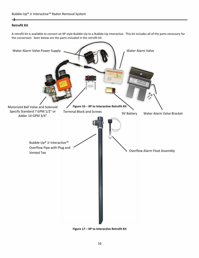
Retrofit Kit A retrofit kit is available to convert an XP style Bubble‐Up to a Bubble‐Up Interactive. This kit includes all of the parts necessary for the conversion. Seen below are the parts included in the retrofit kit.
Figure 16 – XP to Interactive Retrofit Kit
Figure 17 – XP to Interactive Retrofit Kit
Bubble‐Up® Jr Interactive™
Overflow Pipe with Plug and
Vented Tee Overflow Alarm Float Assembly
Water Alarm Valve Power Supply Water Alarm Valve
Water Alarm Valve Bracket9V BatteryTerminal Block and Screws
Motorized Ball Valve and Solenoid Specify Standard 7 GPM 1/2" or
Adder 14 GPM 3/4"

Bubble‐Up® Jr Interactive™ Radon Removal System
17
Parts Listing
Item# Description QTY Unit
BUB057 Bubble‐Up Jr Interactive Tank 1 each
BUB058 Bubble‐Up Jr Interactive Tank Cover 1 each
BUB009 PVC Manifold – air‐water coupling 1 each
BUB004 9" Grid chamber with grids 1 each
BUB011 6' supply cord 16/3, yellow 1 each
BUB007 Solenoid Float switch assembly 1 each
BUB008 Blower 1 each
BUB012A 5" X 1" Gasket #3231 1 each
BUB012B 5" X 1" Top #3628 1 each
BUB012C 5" X 1" Bottom #3629 1 each
BUB035A 3/8" X 2.5" S.S. HEX BOLT 4 each
BUB035B 3/8" S.S. WASHER 4 each
BUB035C 3/8" ZINC PLATED NUT 4 each
BUB300 1/2" Solenoid and Water Alarm Valve Assembly 1 each
BUB310 3/4" Solenoid and Water Alarm Valve Assembly 1 each
BUB020 18" Solenoid Cord 1 each
BUB021 3/16" x 1.25” x 50’ foam gasket 0.05 each
BUB022 2" X 4" SCD 80 TXPE Nipple 2 each
BUB023B 1" X 17" SCD 80 Tube 1 each
BUB026 1.25" X 1" PVC SCD 80 Bushing 1 each
BUB028 2" X 35" Slotted PVC Downcomer 1 each
BUB031B 1/4” SCD 80 Nipple Standoff 1 each
BUB033 #12 X 1.25" Phil Flat Head Tap Screw 8 each
BUB034 #12 X 3” Phil HD Flat Tapping Screw 1 each
BUB035 #14 Finishing Washer 8 each
BUB036 2" Adaptaflex, Air Outlet 1 each
BUB037 1.25" Adaptaflex, Overflow 1 each
BUB038 5/8" Delrin Sleeve 2 each
BUB042 5/8" X 1/2" W/Stop Ell – Nickel Plated 1 each
BUB044 Pump Cord Plug 1 each
BUB045 1/2" SS Pex Insert 2 each
BUB046 1/2" X 20' Pex Tubing 0.1 each
BUB048 2" S.S. Clamp 1 each
BUB051B Sta‐Rite Bottom Suction, 20DOM05121+1 1 each
BUB075A 7 GPM Mech. Pump Control Assembly 1 each
BUB075B 14 GPM Mech. Pump Control Assembly 1 each
BUB080 Meter Control Assembly W/ Transformer 1 each
CD1402‐01 Manifold w/o Ports w/Meter 1 each
CV3630 Meter Control Mounting Plate 1 each
CV3006 Bypass 1 each

Bubble‐Up® Jr Interactive™ Radon Removal System
18
CV3007‐04 1" Plastic Male NPT Assembly 1.5 each
56525B 1 1/4" T X T X T SCD 80 Tee 1 each
56655 1 1/4" SCD 80 Plug 1 each
BUB055A 1/4" npt SS Screen Breather Vent 1 each
BUB031C 1 1/4" X 48" SCD 80 Nipple 1 each
56100 1/4" X 4" SCD 80 Nipple 1 each
BUB031D 1/4" X 1/8" SS R‐Coupling 1 each
BUB055B Alarm Float Adapter ‐ 1‐1/4" x 1/4" 1 each
BUB030F High Water Float Switch 1 each
BUB320 Water Alarm Valve Control W/ Electrode Cord, Transformer and Battery Backup 1 each
BUB055C Water Alarm Control Bracket 1 each
BUB055D Water Alarm Control Bracket Mount 1 each
BUB055E Water Alarm Control Bracket Screw 2 each
BUB055F Water Alarm Control Bracket Nut 2 each
PA‐260‐300 Leak Sensor Terminal Block 1 each
BUB055G Leak Sensor Terminal Block Standoff (1/4" nylon) 2 each
BUB055H Leak Sensor Terminal Block Screw 2 each
BUB009B 1/2" XP Adapter 1 each
CV3151 AB1 Nut 1 each
CV3150 Split Ring 1 each
BUB030G 2" SCD 80 PVC Street X Female Air Outlet Adapter 1 each
MBUB03D Interactive Sticker 1 each
MBUB03 Bubble‐Up Sticker 1 each
BUB035F Meter Control Mounting Screw 4 each
BUB047A/MBUB05 Packaging (box & strapping) 1 each
BUBXP105 Duplex Outlet Assembly 1 each
BUB035J Duplex Outlet Assembly Mounting Screw 2 each
Start‐Up Data

Bubble‐Up® Jr Interactive™ Radon Removal System
19
For service, call: _________________________________________________
Installer: _________________________________________________
Address: _________________________________________________
_________________________________________________
_________________________________________________
Serial number: _________________________________________________
Start‐Up Notes
Fill Rate: _________________________________________________
Radon in: _________________________________________________
Radon out: _________________________________________________