Embed Size (px)
Citation preview
C-300 Series Controller Manual
(Version 1.4)
1617 Sherman Ave. Madison, WI 53704, USA
Phone: 608-310-8770 Fax: 608-310-8774
www.npoint.com [email protected]

Table of Contents Page Chapter 1: Installation ..…………………………………………………………………. 1
1.1 Introduction ……………………………………………………………………… 1 1.2 Unpacking ………………………………………………………………………. 1 1.3 Mounting and Connecting the Nanopositioner ………………………………….. 1 1.4 Software Installation ……………………………………………………………. 3
Chapter 2: Controller Interfaces ………………………………………………………… 6
2.1 Back Panel …………………………………………………………………….... 6 2.2 Front Panel …………………………………………………………………….... 6
Chapter 3: Operation …………………………………………………………………….. 8
3.1 System Power Up ..……………………………………………………………… 8 3.2 nPoint Digital Controller Panel …………………………………………………. 8 3.3 Pull Down Menu Bar Options ….…………………………………………….... 12 3.4 P, I and D Parameter Tuning .………………………………………………….. 18
Chapter 4: Trouble Shooting …………………………………………………………… 21

Chapter 1 Installation 1.1 - Introduction The C-300 series of closed-loop controllers is specially designed to control nPoint nanopositioners. One-, two- and three- channel options are available. A basic nanopositioning system consists of the nanopositioner, the controller, a computer, and software. 1.2 - Unpacking The following items are included in the closed-loop system package:
• Nanopositioner • Nanopositioner installation drawing and test specifications sheet • Controller • Controller power cable • USB cable • Controller manual • CD-ROM with installation software
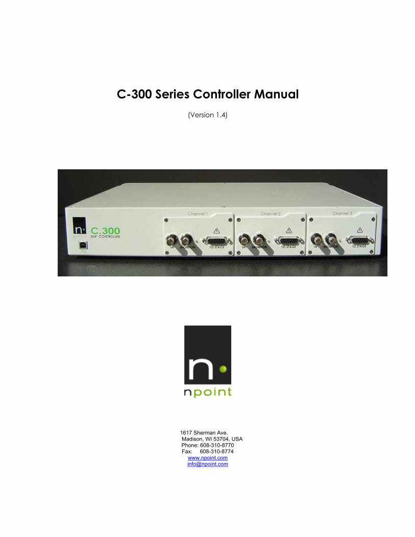
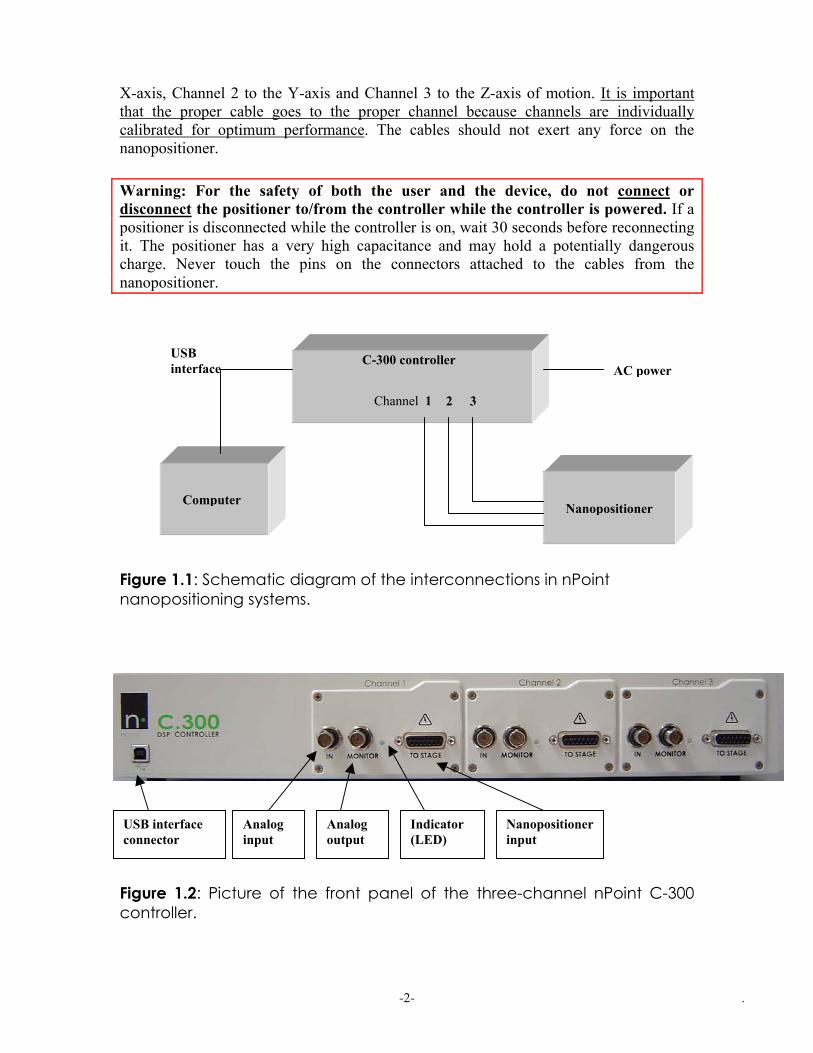
Carefully remove the items from the package. Report any damage or missing items immediately by phone (608-204-8754) or e-mail ([email protected]). Warning: Earth Ground Required The controller must be properly grounded through the power cord. Failure to establish a good earth ground connection may result in dangerous voltages on the controller enclosure. 1.3 - Mounting and Connecting the Nanopositioner Consult the installation drawing included in the shipping package to mount the nanopositioner on a flat surface. The drawing can also be downloaded from our website at www.npoint.com. Figure 1.1 illustrates schematically the interconnections of a three-axes nanopositioning system. Figure 1.2 is a picture of the front panel of the C-300 three-channel controller, showing the input and output connectors. Connect the nanopositioner cables to the front panel of the controller according to the labels. The cable labeled Channel 1 should be connected to the connector labeled TO STAGE in the Channel 1 module on the front panel of the controller, etc. Channel 1 corresponds to the
- - . 1
X-axis, Channel 2 to the Y-axis and Channel 3 to the Z-axis of motion. It is important that the proper cable goes to the proper channel because channels are individually calibrated for optimum performance. The cables should not exert any force on the nanopositioner. Warning: For the safety of both the user and the device, do not connect or disconnect the positioner to/from the controller while the controller is powered. If a positioner is disconnected while the controller is on, wait 30 seconds before reconnecting it. The positioner has a very high capacitance and may hold a potentially dangerous charge. Never touch the pins on the connectors attached to the cables from the nanopositioner.
r
USB interface
r Figure 1.1: Schematic diagramnanopositioning systems.
Analoutp
Analog input
USB interface connector
Figure 1.2: Picture of the froncontroller.
C-300 controlle
2 31
r
o
ogut
t
Channel
f the inte
Indic(LED
panel of
- - 2
rco
ator)
the
r
nnections in
Nanoposiinput
three-chan
Nanopositione
ComputenPoin
tioner
nel nP
AC powe
t
oint C-300
.

1.4 - Software Installation Before installation of the nPoint software, it is recommended that the user install the full version of the latest Windows Service Pack. Microsoft refers to this as a “Network Installation” as opposed to an “Express Installation.” Windows 2000 requires the full version of SP3 or higher. Insert the nPoint provided CD into the PC’s CD-ROM drive. The controller must be powered on when the USB cable is connected to the PC. Power up the controller (power switch is located on the back panel) and connect the supplied USB cable from the front panel of the controller to the PC. Windows will detect that a new device has been connected, and will launch the driver installation wizard, Figure 1.3. Windows XP will ask if you would like to connect to Windows Update to download the driver (See figure 1.3). Select the option “No, not this time” and click the Next button. Select the option to “Install from a list or specific location” and click the Next button (see Figure 1.4). Select the “Include this location in the search” checkbox, click on the Browse button and navigate to the “USB Drivers…” folder on the nPoint CD (see Figure 1.5). Once the folder has been selected, click Next. The C300 USB drivers will now be installed. Windows XP will say that this is not a certified driver; select the option Continue anyway (See Figure 1.6).
Figure 1.3. For Windows XP, choose not to connect to Windows Update
- - . 3

Figure 1.4. Choose Install from a specific location
Figure 1.5. Browse to USB Drivers folder on nPoint CD
- - . 4
Figure 1.6. Select Continue Anyway for Windows XP
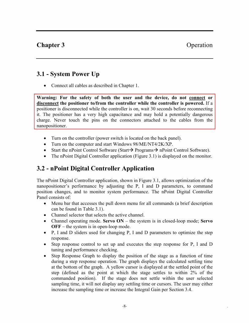
Open the folder named C300 USB Application Install located on the nPoint CD. Double click the C300 USB setup file and then click the Next button for each screen to install the software with default options. The final screen will prompt the user to select Close. This concludes the installation process. Once the software is installed, the nanopositioner can be operated from the PC. To confirm that the software has been properly installed, start the controller software. Go to the Start menu of the PC, select All Programs, and then select the application, nPoint C300 USB…. The nPoint C300 application will be viewable on the monitor. An example of the nPoint C300 application screen is shown in Figure 1.7.
Figure 1.7. The nPoint Digital Controller application screen.
- - . 5

Chapter 2 Controller Interfaces 2.1 - Back Panel The back panel contains the power ON/OFF switch, fuse holder, and A/C mains selector. If installing the controller outside of the U.S. please make sure that the A/C is set to the proper voltage. 2.2 - Front Panel A picture of the front panel of the C-300 Controller is shown in Figure 1.2 for a three-channel configuration. Each channel is equipped with one D-15 connector and two analog I/O connectors. The USB interface connector is common to all channels. 2.2.1 - D-15 Connectors Up to three nanopositioning channels can be connected to one controller. For a two-channel system, the X axis is connected to Channel 1 and the Y axis is connected to Channel 2. For a three-channel system, the X, Y, and Z axes are connected to Channels 1, 2, and 3 respectively. Warning: For the safety of both the user and the device, do not connect or disconnect the positioner to/from the controller while the controller is powered. If a positioner is disconnected while the controller is on, wait 30 seconds before reconnecting it. The positioner has a very high capacitance and may hold a potentially dangerous charge. Never touch the pins on the connectors attached to the cables from the nanopositioner. 2.2.2 - Analog Inputs/Outputs There are two BNC connectors for each channel on the front panel. The BNC connector on the left, labeled ‘IN’ (see Figure 1.2), provides the option to drive the controller with an external analog input. The voltage range of this BNC input is ±10V. The BNC connector on the right, labeled ‘MONITOR’ (see Figure 1.2), is the capacitive-sensor monitor output with a voltage range of ±10V. The sensor monitors are low-pass filtered at 2 kHz and used to determine the absolute position of the nanopositioner stage. The sensor noise RMS value is greater than the position noise specification. Grounding the shields of the sensor output BNCs or connecting the BNCs to a load of less than 100 KΩ may degrade system performance.
- - . 6

Each channel has its own LED indicator. Each LED has two colors to indicate the channel’s operating status. (When the LED is off, the power is off):
LED Color Channel Status Red Open-loop Green Closed-loop
- - . 7
Chapter 3 Operation 3.1 - System Power Up
• Connect all cables as described in Chapter 1. Warning: For the safety of both the user and the device, do not connect or disconnect the positioner to/from the controller while the controller is powered. If a positioner is disconnected while the controller is on, wait 30 seconds before reconnecting it. The positioner has a very high capacitance and may hold a potentially dangerous charge. Never touch the pins on the connectors attached to the cables from the nanopositioner.
• Turn on the controller (power switch is located on the back panel). • Turn on the computer and start Windows 98/ME/NT4/2K/XP. • Start the nPoint Control Software (Start Programs nPoint Control Software). • The nPoint Digital Controller application (Figure 3.1) is displayed on the monitor.
3.2 - nPoint Digital Controller Application The nPoint Digital Controller application, shown in Figure 3.1, allows optimization of the nanopositioner’s performance by adjusting the P, I and D parameters, to command position changes, and to monitor system performance. The nPoint Digital Controller Panel consists of:
• Menu bar that accesses the pull down menu for all commands (a brief description can be found in Table 3.1).
• Channel selector that selects the active channel. • Channel operating mode. Servo ON – the system is in closed-loop mode; Servo
OFF – the system is in open-loop mode. • P, I and D sliders used for changing P, I and D parameters to optimize the step
response. • Step response control to set up and executes the step response for P, I and D
tuning and performance checking. • Step Response Graph to display the position of the stage as a function of time
during a step response operation. The graph displays the calculated settling time at the bottom of the graph. A yellow cursor is displayed at the settled point of the step (defined as the point at which the stage settles to within 2% of the commanded position). If the stage does not settle within the user selected sampling time, it will not display any settling time or cursors. The user may either increase the sampling time or increase the Integral Gain per Section 3.4.
- - . 8

• Status Bar that displays connection status, either Not Connected or Connected to ###### (where ###### is the serial number of the controller), channel position (in microns), and stage settling time for the last step response executed.
Figure 3.1. nPoint Digital Controller panel. This view appears on the monitor following the System Power Up procedure described in Section 3.1.
- - . 9
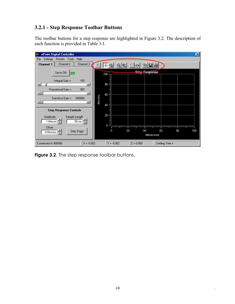
3.2.1 - Step Response Toolbar Buttons The toolbar buttons for a step response are highlighted in Figure 3.2. The description of each function is provided in Table 3.1.
Figure 3.2. The step response toolbar buttons.
- - . 10

Toolbar Function
Allows the user to restore the graph to its original form (before any of the toolbar buttons were used).
Allows the user to scroll the y-axis (position) up and down and the x-axis (time) left and right, by placing and dragging the mouse over the axis of interest.
Allows the user to zoom in the y- and the x-axis by placing and dragging the mouse over the axis of interest.
Allows the user to zoom out by clicking on the button.
Allows the user to zoom in by clicking on the button.
Allows the user to zoom into an area of interest, by clicking and dragging the mouse.
Allows a second cursor on the graph. Both cursors can be moved by placing and dragging the mouse. While the cursors are in motion, the values of intersection with the step response curve are displayed.
Allows the graph to be copied onto the clipboard.
Allows the graph to be copied onto a file.
Allows the graph to be printed.
Table 3.1. Description of the toolbar button functions in the step response graph.
- - . 11
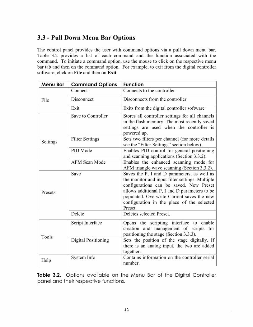
3.3 - Pull Down Menu Bar Options The control panel provides the user with command options via a pull down menu bar. Table 3.2 provides a list of each command and the function associated with the command. To initiate a command option, use the mouse to click on the respective menu bar tab and then on the command option. For example, to exit from the digital controller software, click on File and then on Exit.
Menu Bar Command Options Function Connect Connects to the controller
Disconnect Disconnects from the controller File Exit Exits from the digital controller software Save to Controller Stores all controller settings for all channels
in the flash memory. The most recently saved settings are used when the controller is powered up.
Filter Settings Sets two filters per channel (for more details see the “Filter Settings” section below).
PID Mode Enables PID control for general positioning and scanning applications (Section 3.3.2).
Settings
AFM Scan Mode Enables the enhanced scanning mode for AFM triangle wave scanning (Section 3.3.2).
Save
Saves the P, I and D parameters, as well as the monitor and input filter settings. Multiple configurations can be saved. New Preset allows additional P, I and D parameters to be populated. Overwrite Current saves the new configuration in the place of the selected Preset.
Presets
Delete Deletes selected Preset.
Script Interface Opens the scripting interface to enable creation and management of scripts for positioning the stage (Section 3.3.3). Tools Digital Positioning Sets the position of the stage digitally. If there is an analog input, the two are added together.
Help System Info Contains information on the controller serial number.
Table 3.2. Options available on the Menu Bar of the Digital Controller panel and their respective functions.
- - . 12
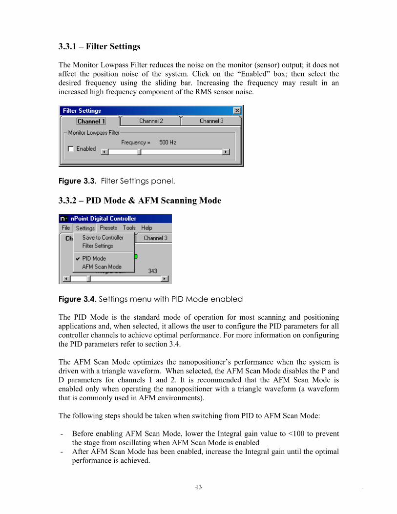
3.3.1 – Filter Settings The Monitor Lowpass Filter reduces the noise on the monitor (sensor) output; it does not affect the position noise of the system. Click on the “Enabled” box; then select the desired frequency using the sliding bar. Increasing the frequency may result in an increased high frequency component of the RMS sensor noise.
Figure 3.3. Filter Settings panel. 3.3.2 – PID Mode & AFM Scanning Mode
Figure 3.4. Settings menu with PID Mode enabled The PID Mode is the standard mode of operation for most scanning and positioning applications and, when selected, it allows the user to configure the PID parameters for all controller channels to achieve optimal performance. For more information on configuring the PID parameters refer to section 3.4. The AFM Scan Mode optimizes the nanopositioner’s performance when the system is driven with a triangle waveform. When selected, the AFM Scan Mode disables the P and D parameters for channels 1 and 2. It is recommended that the AFM Scan Mode is enabled only when operating the nanopositioner with a triangle waveform (a waveform that is commonly used in AFM environments). The following steps should be taken when switching from PID to AFM Scan Mode: - Before enabling AFM Scan Mode, lower the Integral gain value to <100 to prevent
the stage from oscillating when AFM Scan Mode is enabled - After AFM Scan Mode has been enabled, increase the Integral gain until the optimal
performance is achieved.
- - . 13

- Once the optimal Integral gain value has been established for AFM Scan Mode, the user can set the Integral gain to this value before switching to AFM Scan Mode, or the user can create a Preset to automatically change to AFM Scan Mode with the proper Integral gain value (refer to Table 3.2).
3.3.3 – Script Interface To open the Script Interface as seen in Figure 3.5; click Tools, then Script Interface. The script interface allows for a more automated method of controlling the nanopositioner. Commands are listed in text and processed by the controller. The Script Interface is a text box in which commands can be entered. Scripts may be saved and loaded using the File menu. The Tools menu consists of Reset Position and Clear commands. Reset Position will center the stage at zero while Clear will unload the current script and reinitialize the stage information (range, position). The Test button allows for script testing by ensuring all commands given are within the range of the stage. The Run button steps through the script and performs each command that is recognized.
Figure 3.5. Sample Script Interface window. Supported commands: move <channel> <relative position> setposition <channel> <absolute position> closedloop <channel> openloop <channel> wait <time in milliseconds>
- - . 14

Each channel can be placed on one command line, for instance: move x 10 move y 10 Can be rewritten as one command: move x 10 y 10 This can be done for each command that accepts a channel as an argument. A sample script is shown in Figure 3.6, as well as the outcome of running the script. In the status bar (at the bottom of the Script Interface window), the range of the stage will always be shown for reference in the first panel. In the second panel, the absolute position of the stage will be shown. If the script is run using the Test button, the resulting position will be shown and the label will read (Test Posn) to denote the last run was a test and nothing was sent to the controller. The third panel will show the last range error that occurred in the script to facilitate easy editing.
Figure 3.6. Script Interface after running sample script. Each command needs to be on its own input line. The channel arguments can be in any order, for example: move x 10 y 20 and move y 20 x 10
- - . 15

The result of the commands listed above will only differ in the order of the movement. The first line will move X first and then Y while the second line will move Y first, then X. The commands and arguments are not case sensitive. There must be at least one space between the command and each argument. 3.3.4 - Digital Positioning The Digital Positioning Interface is shown in Figure 3.7. To open the Digital Positioning Interface, click Tools and then Digital Positioning. The actual XY position of the stage, at any time, is indicated by the position of the cross in the four-quadrant diagram. The X and Y position co-ordinates can be read from the respective input box located under the graph (in units of micrometers). The X and Y positions can be changed in three ways.
1. Type position values in the input boxes and press Enter or the Set Position button.
2. Move the mouse cursor within the four-quadrant trackpad and click on the desired position. The XY co-ordinates of the mouse cursor can be read at the top of the graph.
3. Click on one of the four directional buttons surrounding the trackpad. The position will change in increments specified by the Step Size input box.
The X and/or Y axis can be locked. When the mouse is moved to a new position only the unlocked axis will change value at the mouse-click. The position of a locked axis can be modified by changing its value in the input box without having to unlock the axis. The Z position may be changed by moving the slider up (positive) or down (negative), or by typing a value in the “Z position” input box. The incremental movement of the Z slider is determined by the Step Size input box.
- - . 16
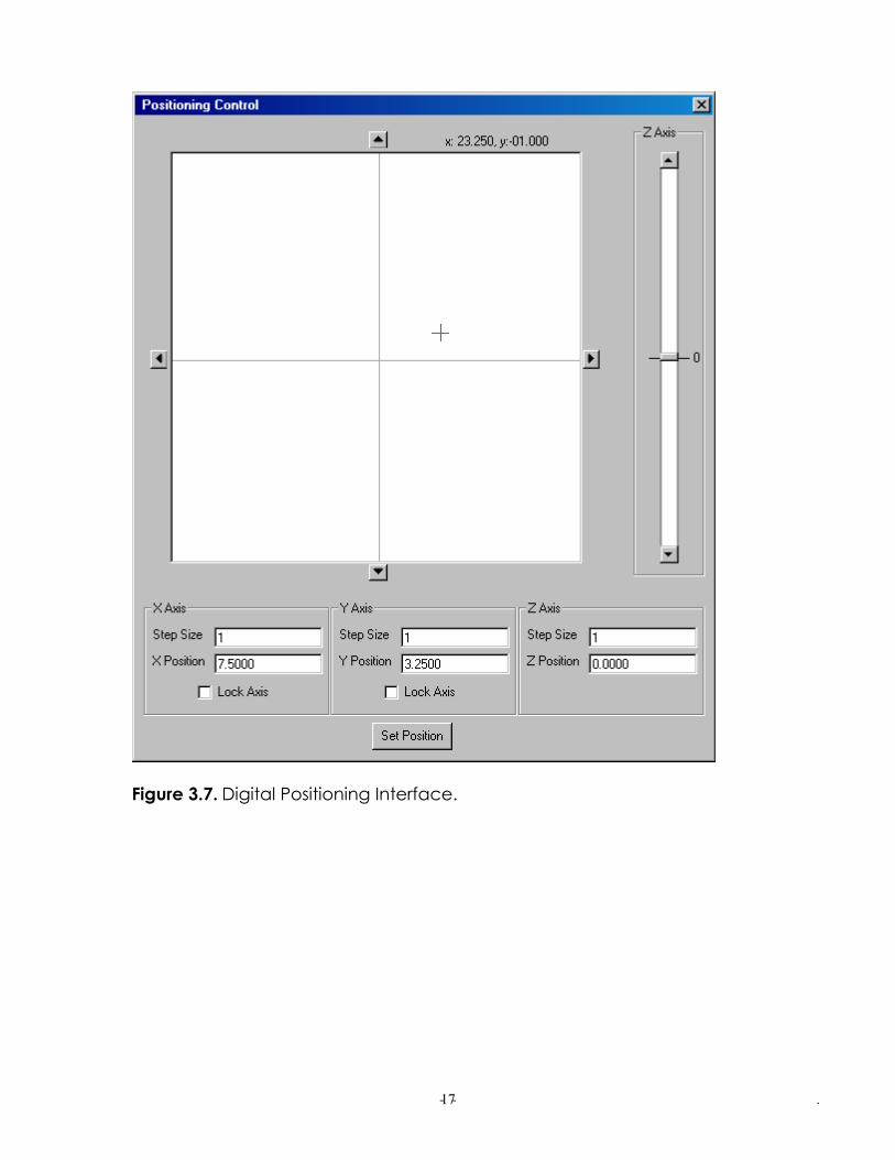
Figure 3.7. Digital Positioning Interface.
- - . 17
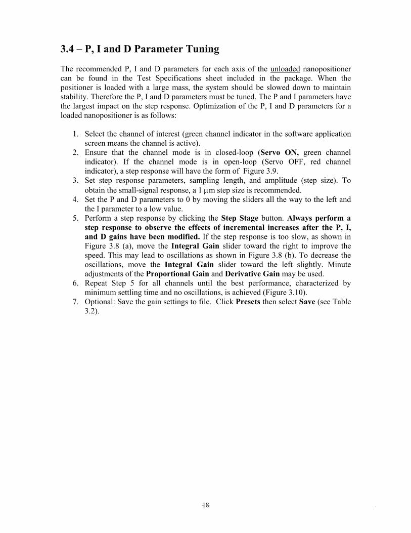
3.4 – P, I and D Parameter Tuning The recommended P, I and D parameters for each axis of the unloaded nanopositioner can be found in the Test Specifications sheet included in the package. When the positioner is loaded with a large mass, the system should be slowed down to maintain stability. Therefore the P, I and D parameters must be tuned. The P and I parameters have the largest impact on the step response. Optimization of the P, I and D parameters for a loaded nanopositioner is as follows:
1. Select the channel of interest (green channel indicator in the software application screen means the channel is active).
2. Ensure that the channel mode is in closed-loop (Servo ON, green channel indicator). If the channel mode is in open-loop (Servo OFF, red channel indicator), a step response will have the form of Figure 3.9.
3. Set step response parameters, sampling length, and amplitude (step size). To obtain the small-signal response, a 1 µm step size is recommended.
4. Set the P and D parameters to 0 by moving the sliders all the way to the left and the I parameter to a low value.
5. Perform a step response by clicking the Step Stage button. Always perform a step response to observe the effects of incremental increases after the P, I, and D gains have been modified. If the step response is too slow, as shown in Figure 3.8 (a), move the Integral Gain slider toward the right to improve the speed. This may lead to oscillations as shown in Figure 3.8 (b). To decrease the oscillations, move the Integral Gain slider toward the left slightly. Minute adjustments of the Proportional Gain and Derivative Gain may be used.
6. Repeat Step 5 for all channels until the best performance, characterized by minimum settling time and no oscillations, is achieved (Figure 3.10).
7. Optional: Save the gain settings to file. Click Presets then select Save (see Table 3.2).
- - . 18

(a) The step response when the loop speed is too slow (insufficient Integral Gain).
(b) The step response when the loop speed is too fast (excess Integral Gain). Figure 3.8. Examples (a) and (b) depict response settling times when loop speed is too slow or too fast.
- - . 19
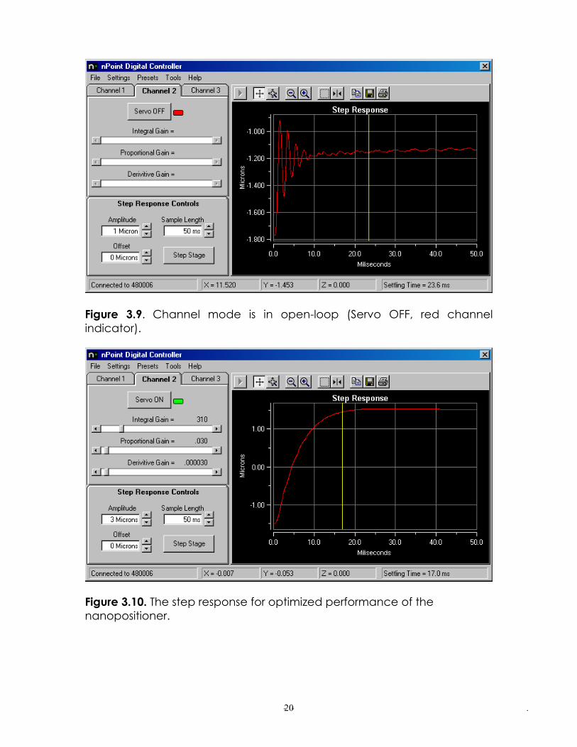
Figure 3.9. Channel mode is in open-loop (Servo OFF, red channel indicator).
Figure 3.10. The step response for optimized performance of the nanopositioner.
- - . 20
- - . 21
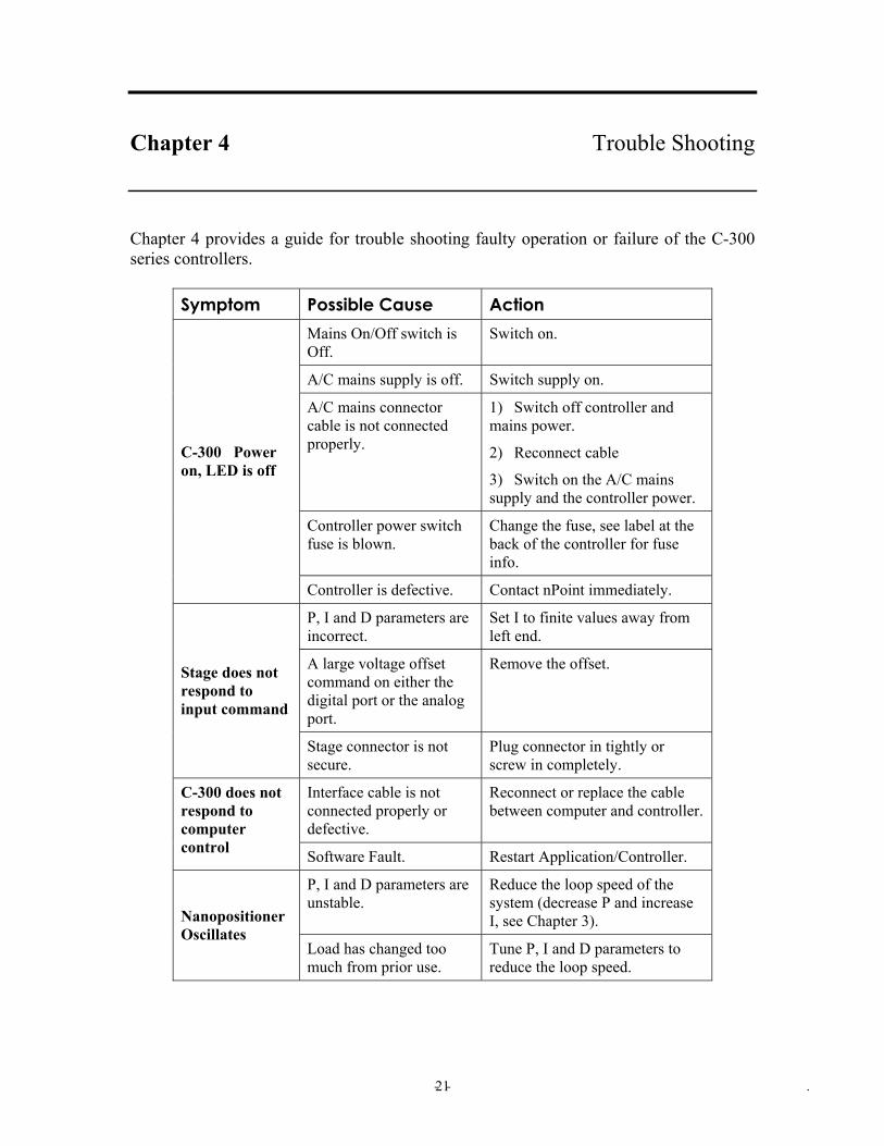
Chapter 4 Trouble Shooting Chapter 4 provides a guide for trouble shooting faulty operation or failure of the C-300 series controllers.
Symptom Possible Cause Action Mains On/Off switch is Off.
Switch on.
A/C mains supply is off. Switch supply on.
A/C mains connector cable is not connected properly.
1) Switch off controller and mains power.
2) Reconnect cable
3) Switch on the A/C mains supply and the controller power.
Controller power switch fuse is blown.
Change the fuse, see label at the back of the controller for fuse info.
C-300 Power on, LED is off
Controller is defective. Contact nPoint immediately.
P, I and D parameters are incorrect.
Set I to finite values away from left end.
A large voltage offset command on either the digital port or the analog port.
Remove the offset. Stage does not respond to input command
Stage connector is not secure.
Plug connector in tightly or screw in completely.
Interface cable is not connected properly or defective.
Reconnect or replace the cable between computer and controller.
C-300 does not respond to computer control Software Fault. Restart Application/Controller.
P, I and D parameters are unstable.
Reduce the loop speed of the system (decrease P and increase I, see Chapter 3). Nanopositioner
Oscillates Load has changed too much from prior use.
Tune P, I and D parameters to reduce the loop speed.