Embed Size (px)
Citation preview
CFD Analysis of Spitfire Aircraft
using TCFD®
Radek David CFD Engineer
CFD SUPPORT LTD [email protected]
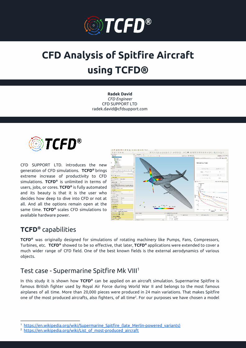
CFD SUPPORT LTD. introduces the new generation of CFD simulations. TCFD® brings extreme increase of productivity to CFD simulations. TCFD® is unlimited in terms of users, jobs, or cores. TCFD® is fully automated and its beauty is that it is the user who decides how deep to dive into CFD or not at all. And all the options remain open at the same time. TCFD® scales CFD simulations to available hardware power.
TCFD® capabilities TCFD® was originally designed for simulations of rotating machinery like Pumps, Fans, Compressors, Turbines, etc. TCFD® showed to be so effective, that later, TCFD® applications were extended to cover a much wider range of CFD field. One of the best known fields is the external aerodynamics of various objects.
Test case - Supermarine Spitfire Mk VIII 1
In this study it is shown how TCFD® can be applied on an aircraft simulation. Supermarine Spitfire is famous British fighter used by Royal Air Force during World War II and belongs to the most famous airplanes of all time. More than 20,000 pieces were produced in 24 main variations. That makes Spitfire one of the most produced aircrafts, also fighters, of all time . For our purposes we have chosen a model 2
1 https://en.wikipedia.org/wiki/Supermarine_Spitfire_(late_Merlin-powered_variants) 2 https://en.wikipedia.org/wiki/List_of_most-produced_aircraft

Spitfire Mk VIII, which CAD model is freely available at GrabCAD . Basic specifications of this particular 3
version are given in the table below.
Spitfire Mk VIII specifications
Length 9.54 m
Wingspan 11.23 m
Height 3.85 m
Wing area 22.5 m2
Empty weight 2633 kg
Max takeoff weight
3638 kg
Maximum speed 656 km/h
Service ceiling 13 000 m
Engine Various Rolls Royce Merlin variants - 27 l supercharged V12, max power 1710 hp
Armament 2 x 20 mm Hispano cannons, 4 x 7.7 mm Browning machine guns, 1 x 227 or 2 x 113 kg bombs
Preprocessing We started with a CAD model of Spitfire in file format STEP. For a professional CFD simulation, the original STEP file is usually too complex and therefore certain preprocessing work has to be done. Using an open-source software Salome, the model is simplified and cleaned. Some tiny and problematic parts are removed. The final surface model is made waterproof. An artificial “cylinder” surrounding the propeller is created, because of the propeller rotation. Another artificial objects is a “bounding box”, which will works
as a virtual wind tunnel (domain boundary), so one can prescribe the boundary conditions. Finally, 2D surface meshes are generated to fit the CAD surface in an acceptable way. Individual STL files, that define the surfaces of the aircraft, bounding box and cylinder are exported. Remember, the preprocessing is extremely important for each CFD workflow. Preprocessing always limits the CFD results and sets the expectations.
TCFD® case setup TCFD® was originally designed for the turbomachinery applications, where many components are connected to each other, and some of them may rotate. Simulating an airplane with the rotating propeller in flight conditions is quite similar, so TCFD® is well suited for that.
3 https://grabcad.com/library/supermarine-spitfire-mk-viii
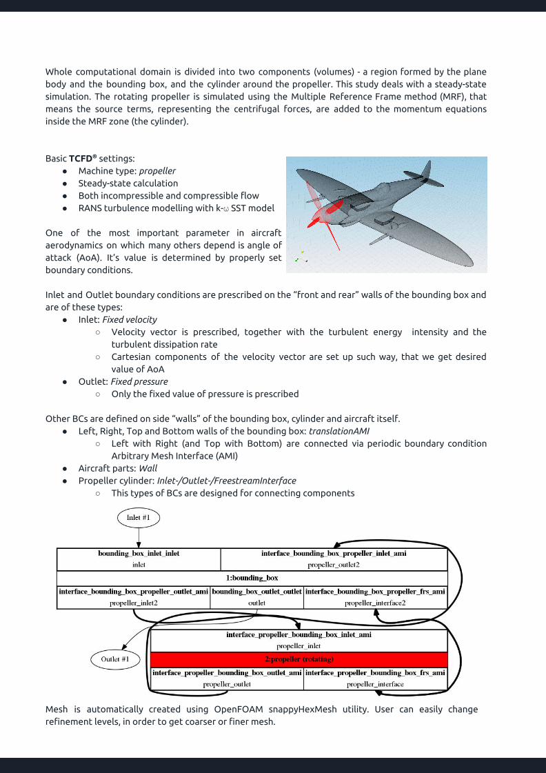
Whole computational domain is divided into two components (volumes) - a region formed by the plane body and the bounding box, and the cylinder around the propeller. This study deals with a steady-state simulation. The rotating propeller is simulated using the Multiple Reference Frame method (MRF), that means the source terms, representing the centrifugal forces, are added to the momentum equations inside the MRF zone (the cylinder). Basic TCFD® settings:
● Machine type: propeller ● Steady-state calculation ● Both incompressible and compressible flow ● RANS turbulence modelling with k-⍵ SST model
One of the most important parameter in aircraft aerodynamics on which many others depend is angle of attack (AoA). It’s value is determined by properly set boundary conditions. Inlet and Outlet boundary conditions are prescribed on the “front and rear” walls of the bounding box and are of these types:
● Inlet: Fixed velocity ○ Velocity vector is prescribed, together with the turbulent energy intensity and the
turbulent dissipation rate ○ Cartesian components of the velocity vector are set up such way, that we get desired
value of AoA ● Outlet: Fixed pressure
○ Only the fixed value of pressure is prescribed Other BCs are defined on side “walls” of the bounding box, cylinder and aircraft itself.
● Left, Right, Top and Bottom walls of the bounding box: translationAMI ○ Left with Right (and Top with Bottom) are connected via periodic boundary condition
Arbitrary Mesh Interface (AMI) ● Aircraft parts: Wall ● Propeller cylinder: Inlet-/Outlet-/FreestreamInterface
○ This types of BCs are designed for connecting components
Mesh is automatically created using OpenFOAM snappyHexMesh utility. User can easily change refinement levels, in order to get coarser or finer mesh.
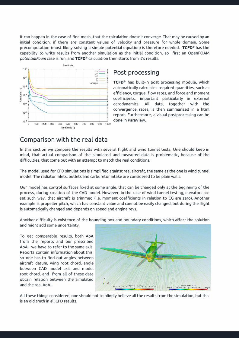
It can happen in the case of fine mesh, that the calculation doesn’t converge. That may be caused by an initial condition, if there are constant values of velocity and pressure for whole domain. Some precomputation (most likely solving a simple potential equation) is therefore needed. TCFD® has the capability to write results from another simulation as the initial condition, so first an OpenFOAM potentialFoam case is run, and TCFD® calculation then starts from it’s results.
Post processing TCFD® has built-in post processing module, which automatically calculates required quantities, such as efficiency, torque, flow rates, and force and moment coefficients, important particularly in external aerodynamics. All data, together with the convergence rates, is then summarized in a html report. Furthermore, a visual postprocessing can be done in ParaView.
Comparison with the real data In this section we compare the results with several flight and wind tunnel tests. One should keep in mind, that actual comparison of the simulated and measured data is problematic, because of the difficulties, that come out with an attempt to match the real conditions. The model used for CFD simulations is simplified against real aircraft, the same as the one is wind tunnel model. The radiator inlets, outlets and carburetor intake are considered to be plain walls. Our model has control surfaces fixed at some angle, that can be changed only at the beginning of the process, during creation of the CAD model. However, in the case of wind tunnel testing, elevators are set such way, that aircraft is trimmed (i.e. moment coefficients in relation to CG are zero). Another example is propeller pitch, which has constant value and cannot be easily changed, but during the flight is automatically changed and depends on speed and engine revs. Another difficulty is existence of the bounding box and boundary conditions, which affect the solution and might add some uncertainty. To get comparable results, both AoA from the reports and our prescribed AoA - we have to refer to the same axis. Reports contain information about this, so one has to find out angles between aircraft datum, wing root chord, angle between CAD model axis and model root chord, and from all of these data obtain relation between the simulated and the real AoA. All these things considered, one should not to blindly believe all the results from the simulation, but this is an old truth in all CFD results.

Test case 1 - Spitfire VIII Attitude Trials 4
The following document from 1945, contains a flight test data of Spitfire VIII, i.e. exactly the same Spitfire model. The most interesting data obtained is lift coefficient curve - dependence of lift coefficient on AoA. Computed results cannot be directly compared to those in the report, because measured CL is not the true one, and has to be corrected for position error. The report gives desired values of corrections. TCFD® setup details:
● Speed 90 m/s (324 km/h) ● Incompressible flow ● AoA 0 ÷ 8° ● Propeller RPM 1145 (engine RPM 2400) ● Mesh 6.3M cells
● Physical quantities of air: default ● Reference pressure 1 atm ● Reference density 1.2 kg/m3
● Dynamic viscosity 1.8 × 10⁻⁵ Pa⋅s
Test case 2 - High speed Wind-tunnel Tests on Models of Four Single-engined Fighters 5
In this document, wind tunnel tests of Spitfire Mk I are presented. This model differs a bit from our Mk VIII, but aerodynamic characteristics should be nearly the same. The report contains many figures, which show various aerodynamic coefficients and their dependencies. Two of them - lift coefficient with respect to the AoA at low speed, and lift carpet (variation of lift coefficient with AoA and Mach number at high speeds) - are compared to our results. The model has to be simplified even more, in order to correspond with wind tunnel model, so the propeller is omitted. Computational domain consists of only one component, and the machine type is stator, as there is nothing to rotate. The real model is ⅙ scale, so it is necessary to either scale the STEP model or choose carefully some variables, so that Mach and Reynolds number match the real ones.
4 https://ww2aircraft.net/forum/attachments/spitfire-mk-8-attitude-trials-pdf.66780/ 5 http://naca.central.cranfield.ac.uk/reports/arc/rm/2535.pdf
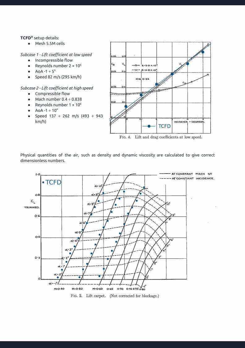
TCFD® setup details:
● Mesh 5.5M cells Subcase 1 - Lift coefficient at low speed
● Incompressible flow ● Reynolds number 2 × 10⁶
● AoA -1 ÷ 5° ● Speed 82 m/s (295 km/h)
Subcase 2 - Lift coefficient at high speed
● Compressible flow ● Mach number 0.4 ÷ 0.838 ● Reynolds number 1 × 10⁶
● AoA -1 ÷ 10° ● Speed 137 ÷ 262 m/s (493 ÷ 943
km/h) Physical quantities of the air, such as density and dynamic viscosity are calculated to give correct dimensionless numbers.

Conclusion It has been shown a complex CFD analysis of Supermarine Spitfire fighter and well demonstrated the capabilities of TCFD® in the field of external aerodynamics. The obtained results have been compared with several interesting wind tunnel and flight measurement data, which were made during and after World War II. The comparisons between CFD results and measurements show mostly a good agreement. There are many others aspects that may be objects for a further investigation. For instance: a grid convergence, transient simulations, other turbulence models, or boundary layer.
www.cfdsupport.com +420 212 243 883 [email protected]