Embed Size (px)
DESCRIPTION
auto level machine by sokkia company
Citation preview
SURVEYING INSTRUMENTS
C300/C310/C320/C330Automatic Level
OPERATOR'S MANUAL
表紙(英文)70-125.fm 1 ページ 2004年7月1日 木曜日 午後6時4分

This is the mark of the JapanSurveying Instruments Manu-facturers Association.
表紙(英文)70-125.fm 2 ページ 2004年7月1日 木曜日 午後6時4分
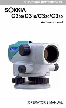
C300/C310/C320/C330Automatic Level
OPERATOR'S MANUAL
Thank you for selecting the C300/C310/C320/C330.• Before using the instrument, please read
this operator's manual carefully.• Verify that all equipment is included.
(See "11. STANDARD EQUIPMENT")• This specifications and general appear-
ance of the instrument may be altered atany time and may differ from thoseappearing in brochures and this manual.
• Some of the diagrams shown in this man-ual may be simplified for easier under-standing.
目次(英文)70-125.fm 1 ページ 2004年7月1日 木曜日 午後6時5分
CONTENTS
1 . PRECAUTIONS FOR SAFE OPERATION•••••••••••••••••••••••••••••••••••1
1.1 GENERAL••••••••••••••••••••••••••••••••••••••21.2 TRIPOD•••••••••••••••••••••••••••••••••••••••••••31.3 STAFF•••••••••••••••••••••••••••••••••••••••••••4
2 . FEATURES OF C300/C310/C320/C330 ••53 . PARTS OF THE INSTRUMENT ••••••••64 . PRELIMINARIES ••••••••••••••••••••••••••••7
4.1 SETTING UP THE INSTRUMENT ••••••••74.2 FOCUSSING AND SIGHTING •••••••••••••9
5 . OPERATION•••••••••••••••••••••••••••••••••••105.1 MEASURING HEIGHT DIFFERENCE •••105.2 MEASURING HORIZONTAL ANGLE•••••125.3 MEASURING DISTANCE USING
THE STADIA LINES •••••••••••••••••••••••••••136 . OPTIONAL ACCESSORIES•••••••••••••14
6.1 DIAGONAL EYEPIECE DE22••••••••••••••147 . CHECKS AND ADJUSTMENTS •••••••15
7.1 CIRCULAR LEVEL •••••••••••••••••••••••••••157.2 AUTOMATIC COMPENSATOR••••••••••••167.3 RETICLE CROSS-LINE
(LINE OF SIGHT)•••••••••••••••••••••••••••••178 . GENERAL PRECAUTIONS •••••••••••••199 . SPECIFICATIONS•••••••••••••••••••••••••••2010 . MAINTENANCE••••••••••••••••••••••••••••••2111 . STANDARD EQUIPMENT
(Packing layout)•••••••••••••••••••••••••••••22
目次(英文)70-125.fm 2 ページ 2004年7月1日 木曜日 午後6時5分
-1-
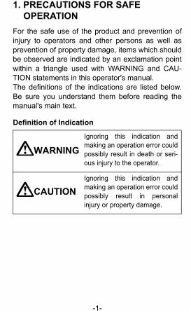
1. PRECAUTIONS FOR SAFE OPERATION
For the safe use of the product and prevention ofinjury to operators and other persons as well asprevention of property damage, items which shouldbe observed are indicated by an exclamation pointwithin a triangle used with WARNING and CAU-TION statements in this operator's manual.The definitions of the indications are listed below.Be sure you understand them before reading themanual's main text.
Definition of Indication
WARNINGIgnoring this indication andmaking an operation error couldpossibly result in death or seri-ous injury to the operator.
CAUTIONIgnoring this indication andmaking an operation error couldpossibly result in personalinjury or property damage.
本文(英文)70-125.fm 1 ページ 2004年7月1日 木曜日 午後6時0分
-2-
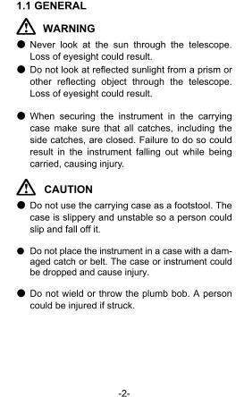
1.1 GENERAL
WARNING● Never look at the sun through the telescope.
Loss of eyesight could result.● Do not look at reflected sunlight from a prism or
other reflecting object through the telescope.Loss of eyesight could result.
● When securing the instrument in the carryingcase make sure that all catches, including theside catches, are closed. Failure to do so couldresult in the instrument falling out while beingcarried, causing injury.
CAUTION● Do not use the carrying case as a footstool. The
case is slippery and unstable so a person couldslip and fall off it.
● Do not place the instrument in a case with a dam-aged catch or belt. The case or instrument couldbe dropped and cause injury.
● Do not wield or throw the plumb bob. A personcould be injured if struck.
本文(英文)70-125.fm 2 ページ 2004年7月1日 木曜日 午後6時0分
-3-
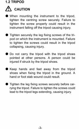
1.2 TRIPOD
CAUTION
● When mounting the instrument to the tripod,tighten the centring screw securely. Failure totighten the screw properly could result in theinstrument falling off the tripod causing injury.
● Tighten securely the leg fixing screws of the tri-pod on which the instrument is mounted. Failureto tighten the screws could result in the tripodcollapsing, causing injury.
● Do not carry the tripod with the tripod shoespointed at other persons. A person could beinjured if struck by the tripod shoes.
● Keep hands and feet away from the tripodshoes when fixing the tripod in the ground. Ahand or foot stab wound could result.
● Tighten the leg fixing screws securely before car-rying the tripod. Failure to tighten the screws couldlead to the tripod legs extending, causing injury.
本文(英文)70-125.fm 3 ページ 2004年7月1日 木曜日 午後6時0分
-4-
1.3 STAFF
CAUTION
● Do not use under thunderous weather condi-tions. Staff is conductive and if struck by lighting,death or injur could result.
● Handle with care when using near high voltagecables or transformers. Staff is conductive andcontact could result in electric shock.
本文(英文)70-125.fm 4 ページ 2004年7月2日 金曜日 午前11時9分
-5-
2. FEATURES OF C300/C310/C320/C330
The C300/C310/C320/C330 is equipped with a fast-action, magnetically-damped, automatic compen-sator. After the instrument has been approximatelyleveled using the circular level, the line of sight isaccurately leveled by the automatic compensatingmechanism.The C300/C310/C320/C330 has been designed toallow stable surveying operations regardless ofenvironmental conditions such as vibration andtemperature changes.
The C300/C310/C320/C330 has a simple horizontalcircle for angle measurement, and the stadia lineson the reticle can be used for approximate distancemeasurement.
The C300/C310/C320/C330 is ideally suited for gen-eral survey work, civil engineering and constructionwork.
本文(英文)70-125.fm 5 ページ 2004年7月1日 木曜日 午後6時0分
-6-
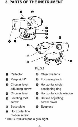
3. PARTS OF THE INSTRUMENT
Fig.3.1
Reflector Objective lens
Peep sight* Focussing knob
Circular level Horizontal circleadjusting screw positioning ringCircular level Horizontal circle windowLeveling foot Reticle adjustingscrew screw coverBase plate EyepieceHorizontal finemotion screw
*The C320/C330 has a gun sight.
1 8
2 9
3 11
4 11
5 12
6 13
7
本文(英文)70-125.fm 6 ページ 2004年7月1日 木曜日 午後6時0分
-7-
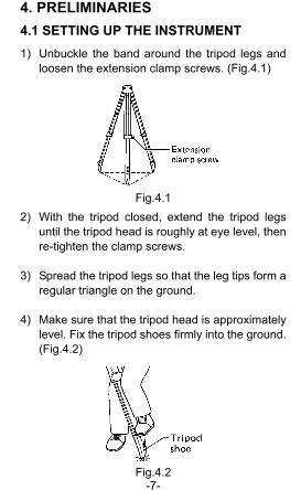
4. PRELIMINARIES4.1 SETTING UP THE INSTRUMENT 1) Unbuckle the band around the tripod legs and
loosen the extension clamp screws. (Fig.4.1)
Fig.4.12) With the tripod closed, extend the tripod legs
until the tripod head is roughly at eye level, thenre-tighten the clamp screws.
3) Spread the tripod legs so that the leg tips form aregular triangle on the ground.
4) Make sure that the tripod head is approximatelylevel. Fix the tripod shoes firmly into the ground.(Fig.4.2)
Fig.4.2
本文(英文)70-125.fm 7 ページ 2004年7月1日 木曜日 午後6時0分
-8-
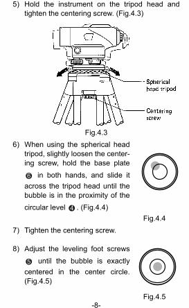
5) Hold the instrument on the tripod head andtighten the centering screw. (Fig.4.3)
Fig.4.36) When using the spherical head
tripod, slightly loosen the center-ing screw, hold the base plate
in both hands, and slide itacross the tripod head until thebubble is in the proximity of thecircular level . (Fig.4.4)
Fig.4.47) Tighten the centering screw.
8) Adjust the leveling foot screws until the bubble is exactly
centered in the center circle.(Fig.4.5)
Fig.4.5
6
4
5
本文(英文)70-125.fm 8 ページ 2004年7月1日 木曜日 午後6時0分
-9-
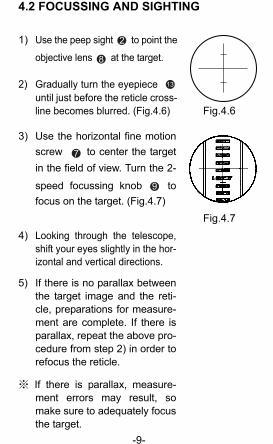
4.2 FOCUSSING AND SIGHTING
1) Use the peep sight to point the
objective lens at the target.
2) Gradually turn the eyepiece until just before the reticle cross-line becomes blurred. (Fig.4.6) Fig.4.6
3) Use the horizontal fine motionscrew to center the targetin the field of view. Turn the 2-
speed focussing knob tofocus on the target. (Fig.4.7)
Fig.4.74) Looking through the telescope,
shift your eyes slightly in the hor-izontal and vertical directions.
5) If there is no parallax betweenthe target image and the reti-cle, preparations for measure-ment are complete. If there isparallax, repeat the above pro-cedure from step 2) in order torefocus the reticle.
※ If there is parallax, measure-ment errors may result, somake sure to adequately focusthe target.
2
8
13
7
9
本文(英文)70-125.fm 9 ページ 2004年7月1日 木曜日 午後6時0分
-10-
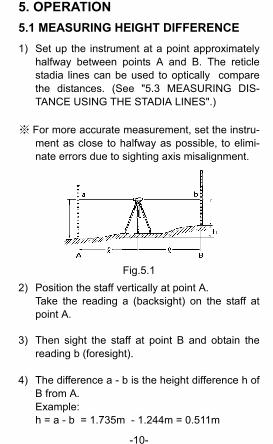
5. OPERATION5.1 MEASURING HEIGHT DIFFERENCE1) Set up the instrument at a point approximately
halfway between points A and B. The reticlestadia lines can be used to optically comparethe distances. (See "5.3 MEASURING DIS-TANCE USING THE STADIA LINES".)
※ For more accurate measurement, set the instru-ment as close to halfway as possible, to elimi-nate errors due to sighting axis misalignment.
Fig.5.12) Position the staff vertically at point A.
Take the reading a (backsight) on the staff atpoint A.
3) Then sight the staff at point B and obtain thereading b (foresight).
4) The difference a - b is the height difference h ofB from A. Example: h = a - b = 1.735m - 1.244m = 0.511m
本文(英文)70-125.fm 10 ページ 2004年7月1日 木曜日 午後6時0分
-11-
Therefore point B is 0.511m higher than point A.(The value of h will be negative if point B islower than point A.)
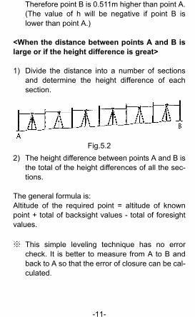
<When the distance between points A and B islarge or if the height difference is great>
1) Divide the distance into a number of sectionsand determine the height difference of eachsection.
Fig.5.22) The height difference between points A and B is
the total of the height differences of all the sec-tions.
The general formula is:Altitude of the required point = altitude of knownpoint + total of backsight values - total of foresightvalues.
※ This simple leveling technique has no errorcheck. It is better to measure from A to B andback to A so that the error of closure can be cal-culated.
本文(英文)70-125.fm 11 ページ 2004年7月1日 木曜日 午後6時0分
-12-
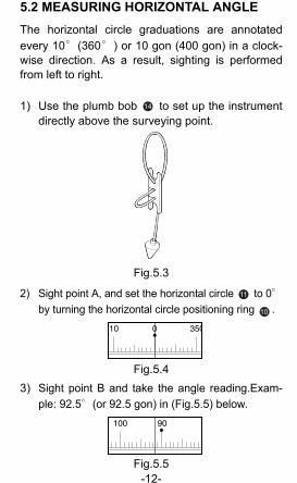
5.2 MEASURING HORIZONTAL ANGLEThe horizontal circle graduations are annotatedevery 10°(360°) or 10 gon (400 gon) in a clock-wise direction. As a result, sighting is performedfrom left to right.
1) Use the plumb bob to set up the instrumentdirectly above the surveying point.
Fig.5.3
2) Sight point A, and set the horizontal circle to 0°by turning the horizontal circle positioning ring .
Fig.5.43) Sight point B and take the angle reading.Exam-
ple: 92.5°(or 92.5 gon) in (Fig.5.5) below.
Fig.5.5
14
11
10
本文(英文)70-125.fm 12 ページ 2004年7月1日 木曜日 午後6時0分
-13-
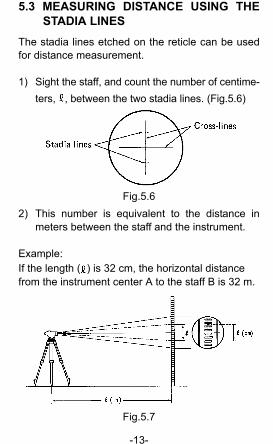
5.3 MEASURING DISTANCE USING THESTADIA LINES
The stadia lines etched on the reticle can be usedfor distance measurement.
1) Sight the staff, and count the number of centime-ters, , between the two stadia lines. (Fig.5.6)
Fig.5.62) This number is equivalent to the distance in
meters between the staff and the instrument.
Example:If the length ( ) is 32 cm, the horizontal distance from the instrument center A to the staff B is 32 m.
Fig.5.7
本文(英文)70-125.fm 13 ページ 2004年7月1日 木曜日 午後6時0分
-14-
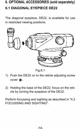
6. OPTIONAL ACCESSORIES (sold separately)6.1 DIAGONAL EYEPIECE DE22
The diagonal eyepiece, DE22, is available for usein restricted viewing positions.
Fig.6.11) Push the DE22 on to the reticle adjusting screw
cover .
2) Holding the base of the DE22, focus on the reti-cle by turning the eyepiece of the DE22.
Perform focussing and sighting as described in "4.2FOCUSSING AND SIGHTING".
12
本文(英文)70-125.fm 14 ページ 2004年7月1日 木曜日 午後6時0分
-15-
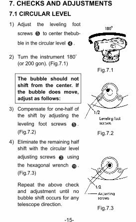
7. CHECKS AND ADJUSTMENTS7.1 CIRCULAR LEVEL1) Adjust the leveling foot
screws to center thebub-
ble in the circular level .
2) Turn the instrument 180°(or 200 gon). (Fig.7.1)
Fig.7.1The bubble should notshift from the center. Ifthe bubble does move,adjust as follows:
3) Compensate for one-half ofthe shift by adjusting theleveling foot screws .(Fig.7.2) Fig.7.2
4) Eliminate the remaining halfshift with the circular leveladjusting screws usingthe hexagonal wrench .(Fig.7.3)
Repeat the above checkand adjustment until nobubble shift occurs for anytelescope direction.
Fig.7.3
5
4
5
3
15
本文(英文)70-125.fm 15 ページ 2004年7月1日 木曜日 午後6時0分
-16-
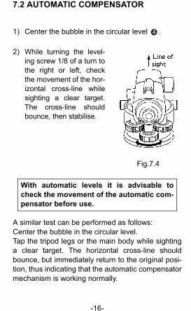
7.2 AUTOMATIC COMPENSATOR
1) Center the bubble in the circular level .
2) While turning the level-ing screw 1/8 of a turn tothe right or left, checkthe movement of the hor-izontal cross-line whilesighting a clear target.The cross-line shouldbounce, then stabilise.
Fig.7.4
With automatic levels it is advisable tocheck the movement of the automatic com-pensator before use.
A similar test can be performed as follows:Center the bubble in the circular level.Tap the tripod legs or the main body while sightinga clear target. The horizontal cross-line shouldbounce, but immediately return to the original posi-tion, thus indicating that the automatic compensatormechanism is working normally.
4
本文(英文)70-125.fm 16 ページ 2004年7月1日 木曜日 午後6時23分
-17-
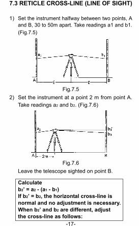
7.3 RETICLE CROSS-LINE (LINE OF SIGHT)
1) Set the instrument halfway between two points, Aand B, 30 to 50m apart. Take readings a1 and b1.(Fig.7.5)
Fig.7.52) Set the instrument at a point 2 m from point A.
Take readings a2 and b2. (Fig.7.6)
Fig.7.6Leave the telescope sighted on point B.
Calculateb2’ = a2 - (a1 - b1)If b2’ = b2, the horizontal cross-line is normal and no adjustment is necessary.When b2’ and b2 are different, adjust the cross-line as follows:
本文(英文)70-125.fm 17 ページ 2004年7月1日 木曜日 午後6時0分
-18-
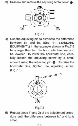
3) Unscrew and remove the adjusting screw cover .
Fig.7.74) Use the adjusting pin to eliminate the difference
between b2’ and b2. (See "11. STANDARDEQUIPMENT".) In the example shown in Fig.7.6b2 is larger than b2’. The horizontal line needs tobe lowered. To lower the horizontal line, care-fully loosen the adjusting screw by a smallamount using the adjusting pin . To raise thehorizontal line, tighten the adjusting screw.(Fig.7.8)
Fig.7.85) Repeat steps 1) and 2) of the adjustment proce-
dure until the difference between b2’ and b2 issmall.
12
16
本文(英文)70-125.fm 18 ページ 2004年7月1日 木曜日 午後6時0分
-19-
8. GENERAL PRECAUTIONS
1) The C300/C310/C320/C330 is a precision instru-ment. Handle with care and avoid heavy shocks andvibration.
2) Never place the instrument directly on theground.
3) When the instrument is left on the tripod, capthe objective lens and cover the entireinstrument with the vinyl cover pro-vided.(See "11. STANDARD EQUIPMENT".)
4) To clean the instrument or carrying case, lightlymoisten a soft cloth in a mild detergent solution.Wring out excess water until the cloth is slightlydamp, then carefully wipe the surface of theunit. Do not use any organic solvents or alkalinecleaning solutions.
5) When the instrument is placed in the case,store the accessories in their specified places.
20
18
本文(英文)70-125.fm 19 ページ 2004年7月1日 木曜日 午後6時0分
-20-
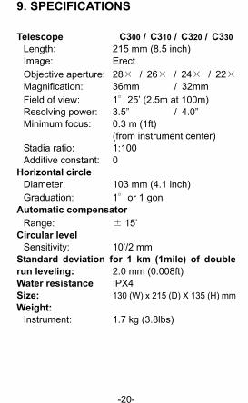
9. SPECIFICATIONS
Telescope C300 / C310 / C320 / C330Length: 215 mm (8.5 inch)Image: ErectObjective aperture: 28× / 26× / 24× / 22×Magnification: 36mm / 32mmField of view: 1°25’ (2.5m at 100m)Resolving power: 3.5” / 4.0”Minimum focus: 0.3 m (1ft)
(from instrument center)Stadia ratio: 1:100Additive constant: 0
Horizontal circleDiameter: 103 mm (4.1 inch)Graduation: 1°or 1 gon
Automatic compensatorRange: ± 15’
Circular levelSensitivity: 10’/2 mm
Standard deviation for 1 km (1mile) of doublerun leveling: 2.0 mm (0.008ft)Water resistance IPX4 Size: 130 (W) x 215 (D) X 135 (H) mmWeight:
Instrument: 1.7 kg (3.8lbs)
本文(英文)70-125.fm 20 ページ 2004年7月1日 木曜日 午後6時39分
-21-
10. MAINTENANCE
1) Check the tripod for loose fit and loose screws.
2) Wipe off moisture completely if the instrumentgets wet during survey work.
3) Always clean the instrument before returning itto the case. The lens requires special care.Dust it off with a clean cloth first to remove tinyparticles. Then, after providing a little condensa-tion by breathing on the lens, wipe it with a softclean cloth or lens tissue,
4) If any trouble is found on the rotatable portion,screws or optical parts (e.g. lens), contact ouragent.
5) Store the instrument in a dry room where thetemperature remains fairly constant.
本文(英文)70-125.fm 21 ページ 2004年7月1日 木曜日 午後6時0分
-22-
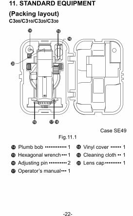
11. STANDARD EQUIPMENT(Packing layout)C300/C310/C320/C330
Case SE49Fig.11.1
Plumb bob •••••••••••• 1 Vinyl cover •••••• 1 Hexagonal wrench••• 1 Cleaning cloth •• 1 Adjusting pin •••••••••• 2 Lens cap••••••••• 1 Operator’s manual••• 1
18
16
1514
19
20
17
14 18
15 19
16 20
17
本文(英文)70-125.fm 22 ページ 2004年7月1日 木曜日 午後6時30分

-23-
MEMO
本文(英文)70-125.fm 23 ページ 2004年7月1日 木曜日 午後6時0分

表紙(英文)70-125.fm 3 ページ 2004年7月1日 木曜日 午後6時4分

1st ed. 01-0406 Printed in China ©2004 SOKKIA CO., LTD.
表紙(英文)70-125.fm 4 ページ 2004年7月1日 木曜日 午後6時4分