Embed Size (px)
Citation preview
Hardware Siemens
Hardware
Contents1 HiPath 4000 V2.0 . . . . . . . . . . . . . . . . . . . . . . . . . . . . . . . . . . . . . . . . . . . . . . . . . . . . . 31.1 AMO DBC . . . . . . . . . . . . . . . . . . . . . . . . . . . . . . . . . . . . . . . . . . . . . . . . . . . . . . . . . . . 31.2 New Control unit in the HiPath 4000 V2.0 . . . . . . . . . . . . . . . . . . . . . . . . . . . . . . . . . . . 5
1.2.1 cPCI - Control shelf . . . . . . . . . . . . . . . . . . . . . . . . . . . . . . . . . . . . . . . . . . . . . 51.2.1.1 Versions of configuration . . . . . . . . . . . . . . . . . . . . . . . . . . . . . . . . . . . . . . . . . 71.2.2 AMO Usage . . . . . . . . . . . . . . . . . . . . . . . . . . . . . . . . . . . . . . . . . . . . . . . . . . 121.2.3 Control board DSCXL . . . . . . . . . . . . . . . . . . . . . . . . . . . . . . . . . . . . . . . . . . 131.2.4 HDMO module . . . . . . . . . . . . . . . . . . . . . . . . . . . . . . . . . . . . . . . . . . . . . . . . 211.2.5 New HD - Layout . . . . . . . . . . . . . . . . . . . . . . . . . . . . . . . . . . . . . . . . . . . . . . 241.2.5.1 HD - Layout HiPath 4000 V1.0. . . . . . . . . . . . . . . . . . . . . . . . . . . . . . . . . . . . 241.2.5.2 HD - Layout HiPath 4000 V2.0. . . . . . . . . . . . . . . . . . . . . . . . . . . . . . . . . . . . 251.2.6 SF2X8 board . . . . . . . . . . . . . . . . . . . . . . . . . . . . . . . . . . . . . . . . . . . . . . . . . 271.2.7 MCM module . . . . . . . . . . . . . . . . . . . . . . . . . . . . . . . . . . . . . . . . . . . . . . . . . 311.2.8 RTM module. . . . . . . . . . . . . . . . . . . . . . . . . . . . . . . . . . . . . . . . . . . . . . . . . . 351.2.9 Power supplies. . . . . . . . . . . . . . . . . . . . . . . . . . . . . . . . . . . . . . . . . . . . . . . . 411.2.10 Fan Tray. . . . . . . . . . . . . . . . . . . . . . . . . . . . . . . . . . . . . . . . . . . . . . . . . . . . . 44
1.3 LTU-Shelf - AP 3700-13 SAPP (Synergy Access Point Platform) . . . . . . . . . . . . . . . . 471.3.1 Shelf population (Front) . . . . . . . . . . . . . . . . . . . . . . . . . . . . . . . . . . . . . . . . . 481.3.2 Configuration rear view . . . . . . . . . . . . . . . . . . . . . . . . . . . . . . . . . . . . . . . . . 491.3.3 AP 3700-13 Backplane Connections . . . . . . . . . . . . . . . . . . . . . . . . . . . . . . . 501.3.4 Highway - view. . . . . . . . . . . . . . . . . . . . . . . . . . . . . . . . . . . . . . . . . . . . . . . . 511.3.5 Numbering of the LTU-Slots. . . . . . . . . . . . . . . . . . . . . . . . . . . . . . . . . . . . . . 521.3.6 AMO-Commands . . . . . . . . . . . . . . . . . . . . . . . . . . . . . . . . . . . . . . . . . . . . . . 521.3.7 Control board LTUCA for AP 3700-13 . . . . . . . . . . . . . . . . . . . . . . . . . . . . . . 53
1.4 IPDA - AP 3700-9 SAPP (Synergy Access Point Platform). . . . . . . . . . . . . . . . . . . . . 59
EN4416EN20EN© 2004 Siemens AG
1
2
HardwareSiemens
1.4.1 Shelf population (Front). . . . . . . . . . . . . . . . . . . . . . . . . . . . . . . . . . . . . . . . . 601.4.2 Rear view of the AP 3700-9 populated with patch panels. . . . . . . . . . . . . . . 611.4.3 Shelf Population (Rear) without Patch Panels . . . . . . . . . . . . . . . . . . . . . . . 621.4.4 AP 3700-9 Backplane Connections . . . . . . . . . . . . . . . . . . . . . . . . . . . . . . . 631.4.5 Highway - view . . . . . . . . . . . . . . . . . . . . . . . . . . . . . . . . . . . . . . . . . . . . . . . 641.4.6 Numbering of the LTU-Slots . . . . . . . . . . . . . . . . . . . . . . . . . . . . . . . . . . . . . 641.4.7 AMO-Commands . . . . . . . . . . . . . . . . . . . . . . . . . . . . . . . . . . . . . . . . . . . . . 651.4.8 Control board NCUI2 for AP3700-9 / AP3500 / AP3300. . . . . . . . . . . . . . . . 671.4.9 LUNA 2 Power supply . . . . . . . . . . . . . . . . . . . . . . . . . . . . . . . . . . . . . . . . . . 71
1.5 Specification data of the power supplies . . . . . . . . . . . . . . . . . . . . . . . . . . . . . . . . . . 731.5.1 ACPCI S30124-X5166-X. . . . . . . . . . . . . . . . . . . . . . . . . . . . . . . . . . . . . . . 731.5.2 DCPCI S30124-X167-X . . . . . . . . . . . . . . . . . . . . . . . . . . . . . . . . . . . . . . . 731.5.3 Luna 2 S30122-K7686-M1 . . . . . . . . . . . . . . . . . . . . . . . . . . . . . . . . . . . . . . 731.5.4 STMI2 board . . . . . . . . . . . . . . . . . . . . . . . . . . . . . . . . . . . . . . . . . . . . . . . . . 75
1.6 AMO CONSY . . . . . . . . . . . . . . . . . . . . . . . . . . . . . . . . . . . . . . . . . . . . . . . . . . . . . . . 792 Hardware supported and not supported . . . . . . . . . . . . . . . . . . . . . . . . . . . . . . . . 812.1 Newly marketed Periphery-Boards in HiPath 4000 . . . . . . . . . . . . . . . . . . . . . . . . . . 812.2 Peripheral boards supported in HiPath 4000 . . . . . . . . . . . . . . . . . . . . . . . . . . . . . . . 842.3 Peripheral Boards No longer supported in HiPath 4000 . . . . . . . . . . . . . . . . . . . . . . 85
EN4416EN20EN© 2004 Siemens AG
HiPath 4000 V2.0 Siemens
1 HiPath 4000 V2.0
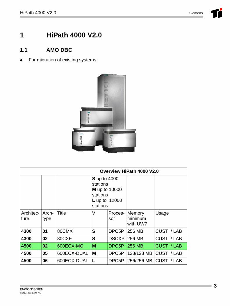
1.1 AMO DBC
● For migration of existing systems
Overview HiPath 4000 V2.0
S up to 4000 stationsM up to 10000 stationsL up to012000 stations
Architec-ture
Arch-type
Title V Proces-sor
Memory minimumwith UW7
Usage
4300 01 80CMX S DPC5P 256 MB CUST / LAB
4300 02 80CXE S DSCXP 256 MB CUST / LAB
4500 02 600ECX-MO M DPC5P 256 MB CUST / LAB
4500 05 600ECX-DUAL M DPC5P 128/128 MB CUST / LAB
4500 06 600ECX-DUAL L DPC5P 256/256 MB CUST / LAB
EN0000DE00EN© 2004 Siemens AG
3
4
HiPath 4000 V2.0Siemens
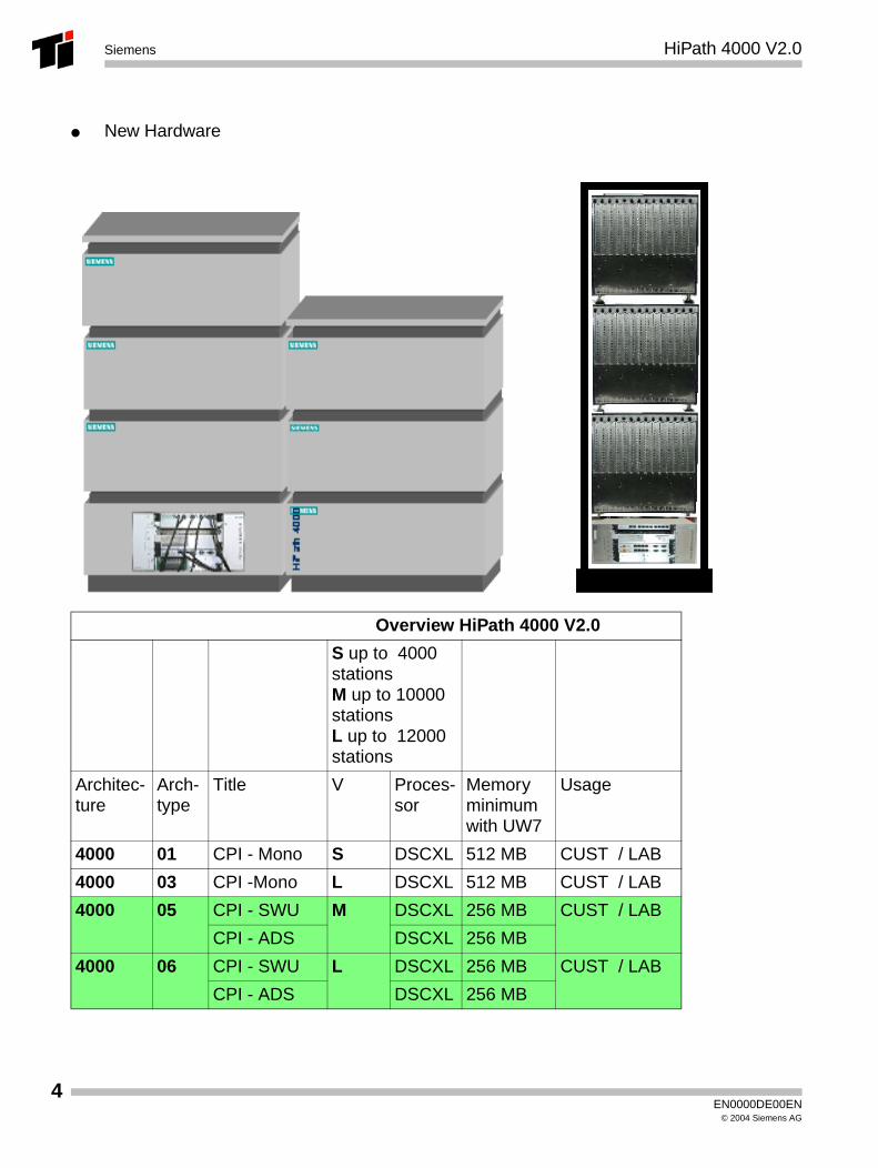
● New Hardware
Overview HiPath 4000 V2.0
S up to04000 stationsM up to 10000 stationsL up to012000 stations
Architec-ture
Arch-type
Title V Proces-sor
Memory minimumwith UW7
Usage
4000 01 CPI - Mono S DSCXL 512 MB CUST / LAB
4000 03 CPI -Mono L DSCXL 512 MB CUST / LAB
4000 05 CPI - SWU M DSCXL 256 MB CUST / LAB
CPI - ADS DSCXL 256 MB
4000 06 CPI - SWU L DSCXL 256 MB CUST / LAB
CPI - ADS DSCXL 256 MB
EN0000DE00EN© 2004 Siemens AG
cPCI Control unit HiPath 4000 V2.0 Siemens
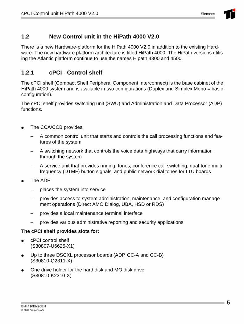
1.2 New Control unit in the HiPath 4000 V2.0
There is a new Hardware-platform for the HiPath 4000 V2.0 in addition to the existing Hard-ware. The new hardware platform architecture is titled HiPath 4000. The HiPath versions utilis-ing the Atlantic platform continue to use the names Hipath 4300 and 4500.
1.2.1 cPCI - Control shelf
The cPCI shelf (Compact Shelf Peripheral Component Interconnect) is the base cabinet of the HiPath 4000 system and is available in two configurations (Duplex and Simplex Mono = basic configuration).
The cPCI shelf provides switching unit (SWU) and Administration and Data Processor (ADP) functions.
● The CCA/CCB provides:
– A common control unit that starts and controls the call processing functions and fea-tures of the system
– A switching network that controls the voice data highways that carry information through the system
– A service unit that provides ringing, tones, conference call switching, dual-tone multi frequency (DTMF) button signals, and public network dial tones for LTU boards
● The ADP
– places the system into service
– provides access to system administration, maintenance, and configuration manage-ment operations (Direct AMO Dialog, UBA, HSD or RDS)
– provides a local maintenance terminal interface
– provides various administrative reporting and security applications
The cPCI shelf provides slots for:
● cPCI control shelf(S30807-U6625-X1)
● Up to three DSCXL processor boards (ADP, CC-A and CC-B)(S30810-Q2311-X)
● One drive holder for the hard disk and MO disk drive(S30810-K2310-X)
EN4416EN20EN© 2004 Siemens AG
5
6
cPCI Control unit HiPath 4000 V2.0Siemens
● Two power supplies (ACPCI or DCPCI)(S30122-K7682-M1) or (S30122-K7682-C1)(S30122-K7683-M1) or (S30122-K7683-C1)
● One SF2X8 LAN switch board(S30810-Q2309-X)
● Two slots for fans
● One connector module (at the back of the shelf) for peripheral expansion boxes RTM (Rear Transition Module)(S30810-Q2312-X)
● One control board (at the back of the shelf) MCM (Management and Control Module)(S30810-Q2313-X)
EN4416EN20EN© 2004 Siemens AG
cPCI Control unit HiPath 4000 V2.0 Siemens
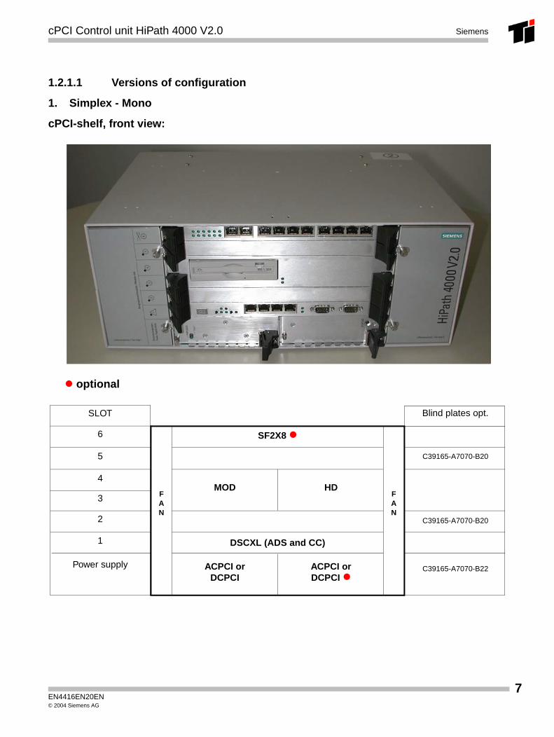
1.2.1.1 Versions of configuration
1. Simplex - Mono
cPCI-shelf, front view:
SLOT Blind plates opt.
6
5
4
3
2
Power supply
1
C39165-A7070-B20
C39165-A7070-B20
C39165-A7070-B22
SF2X8
MOD HD
ACPCI orDCPCI
DSCXL (ADS and CC)
ACPCI orDCPCI
FAN
FAN
optional
EN4416EN20EN© 2004 Siemens AG
7

8
cPCI Control unit HiPath 4000 V2.0Siemens
cPCI-shelf, rear view:
Modules:
● RTM (Rear Transision Module) for LTU connections
● MCM (Management and Control Module) for the alarm contacts and ALUM
SLOT Blind plates opt.
6
5
4
3
2
MCM
1
C39165-A7070-B21
C39165-A7070-B20
C39165-A7070-B20
RTM
MCM
FAN
FAN
EN4416EN20EN© 2004 Siemens AG
cPCI Control unit HiPath 4000 V2.0 Siemens
2. Duplex
● To extend the basic configuration (Simplex Mono) of the cPCI-shelf , the control shelf can be extended by the following modules on the front side:
– 2x DSCXL: S30810-Q2311-X
– 1x SF2X8: S30810-Q2309-X optional
● Concurrently the shelf is extended by the following module on the back side:
– 1x RTM: S30810-Q2312-x
EN4416EN20EN© 2004 Siemens AG
9
10
cPCI Control unit HiPath 4000 V2.0Siemens
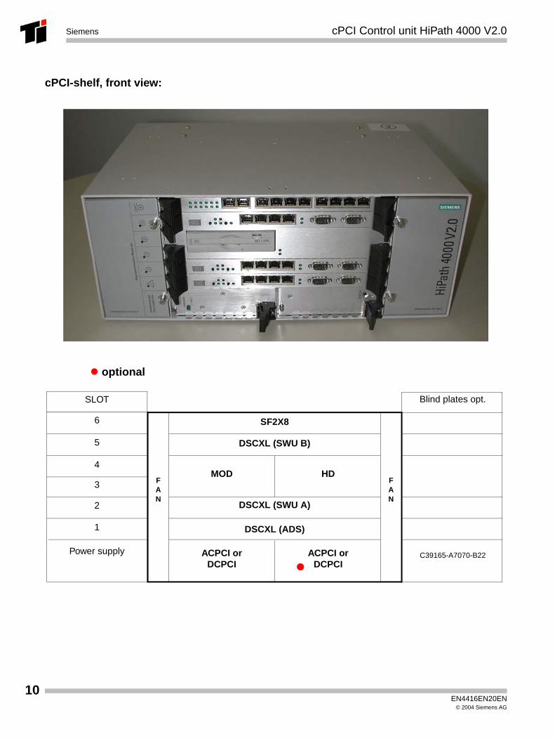
cPCI-shelf, front view:
SLOT Blind plates opt.
6
5
4
3
2
Power supply
1
C39165-A7070-B22
SF2X8
DSCXL (SWU B)
MOD HD
ACPCI orDCPCI
DSCXL (SWU A)
DSCXL (ADS)
ACPCI orDCPCI
FAN
FAN
optional
EN4416EN20EN© 2004 Siemens AG
cPCI Control unit HiPath 4000 V2.0 Siemens
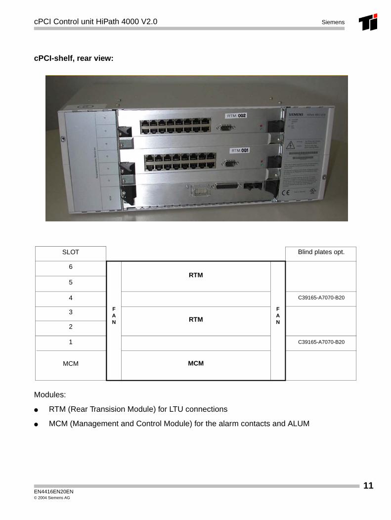
cPCI-shelf, rear view:
Modules:
● RTM (Rear Transision Module) for LTU connections
● MCM (Management and Control Module) for the alarm contacts and ALUM
SLOT Blind plates opt.
6
5
4
3
2
MCM
1
C39165-A7070-B20
C39165-A7070-B20
RTM
RTM
MCM
FAN
FAN
EN4416EN20EN© 2004 Siemens AG
11
12
cPCI Control unit HiPath 4000 V2.0Siemens
1.2.2 AMO Usage
ADD-UCSU:UNIT=LTG,LTG=1,SIPARTNO="Q2312-X"; (RTM Board)
EN4416EN20EN© 2004 Siemens AG
DSCXL Siemens
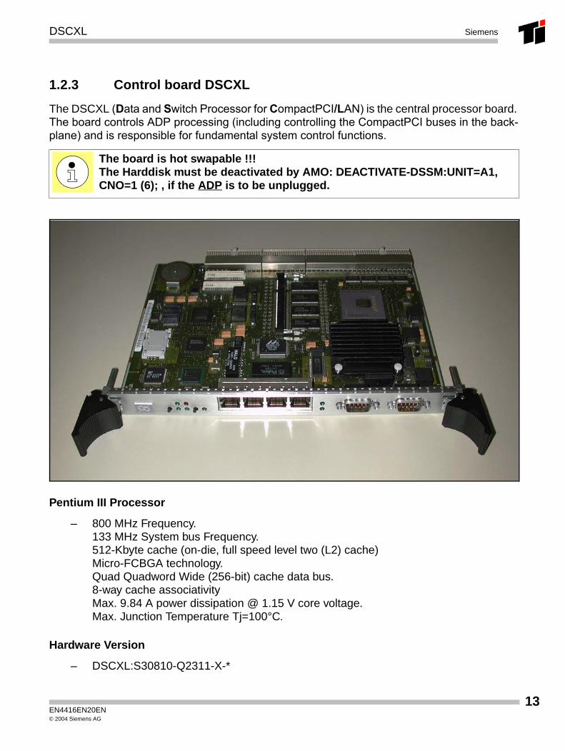
1.2.3 Control board DSCXL
The DSCXL (Data and Switch Processor for CompactPCI/LAN) is the central processor board. The board controls ADP processing (including controlling the CompactPCI buses in the back-plane) and is responsible for fundamental system control functions.
Pentium III Processor
– 800 MHz Frequency.133 MHz System bus Frequency.512-Kbyte cache (on-die, full speed level two (L2) cache)Micro-FCBGA technology.Quad Quadword Wide (256-bit) cache data bus.8-way cache associativityMax. 9.84 A power dissipation @ 1.15 V core voltage.Max. Junction Temperature Tj=100°C.
Hardware Version
– DSCXL:S30810-Q2311-X-*
The board is hot swapable !!!The Harddisk must be deactivated by AMO: DEACTIVATE-DSSM:UNIT=A1, CNO=1 (6); , if the ADP is to be unplugged.
EN4416EN20EN© 2004 Siemens AG
13
14
DSCXLSiemens
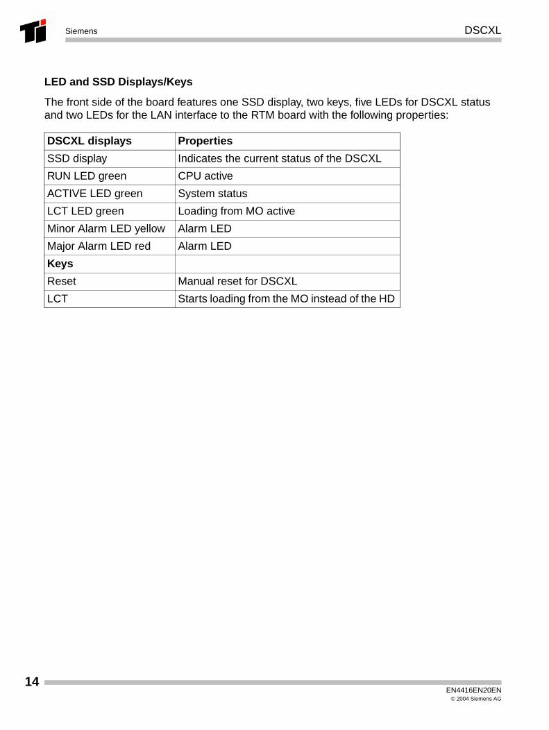
LED and SSD Displays/Keys
The front side of the board features one SSD display, two keys, five LEDs for DSCXL status and two LEDs for the LAN interface to the RTM board with the following properties:
DSCXL displays Properties
SSD display Indicates the current status of the DSCXL
RUN LED green CPU active
ACTIVE LED green System status
LCT LED green Loading from MO active
Minor Alarm LED yellow Alarm LED
Major Alarm LED red Alarm LED
Keys
Reset Manual reset for DSCXL
LCT Starts loading from the MO instead of the HD
EN4416EN20EN© 2004 Siemens AG
DSCXL Siemens
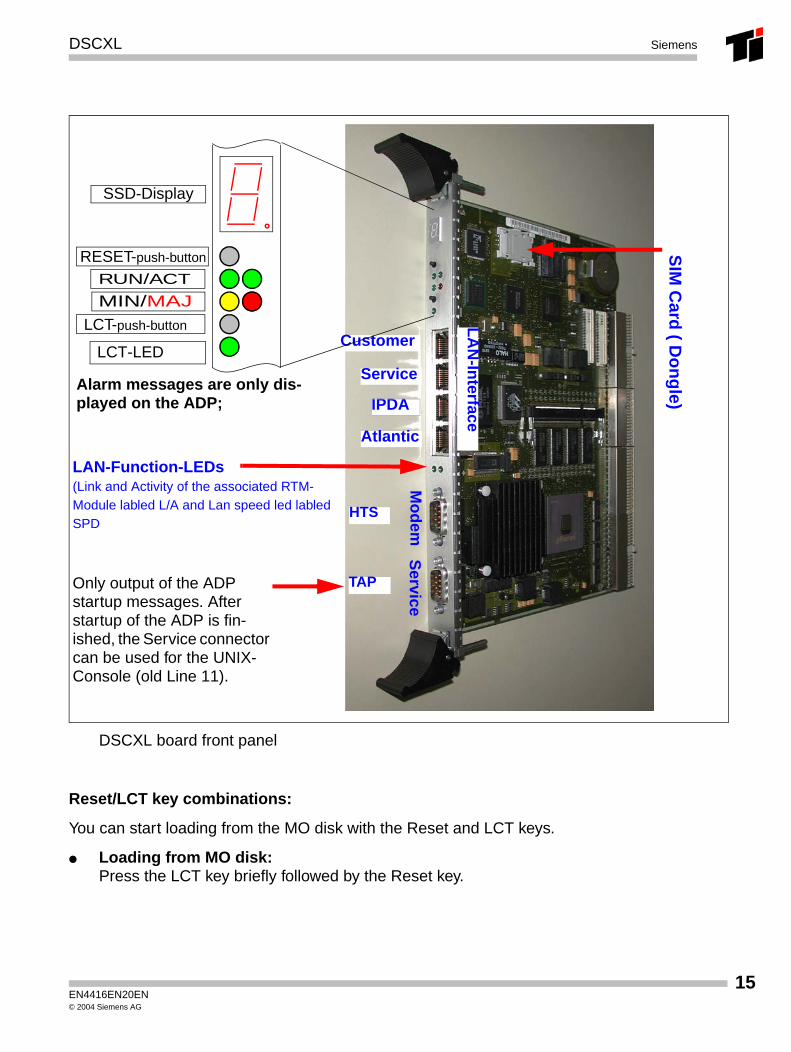
DSCXL board front panel
Reset/LCT key combinations:
You can start loading from the MO disk with the Reset and LCT keys.
● Loading from MO disk:Press the LCT key briefly followed by the Reset key.
LAN-Function-LEDs (Link and Activity of the associated RTM-Module labled L/A and Lan speed led labled SPD
Mo
dem
Service
Customer
Service
IPDA
Atlantic
RESET-push-button
RUN/ACT
MIN/MAJ
LCT-LED
TAP
HTS
SSD-Display
LA
N-In
terfaceLCT-push-button
SIM
Card
( Do
ng
le)
Only output of the ADP startup messages. After startup of the ADP is fin-ished, the Service connector can be used for the UNIX-Console (old Line 11).
Alarm messages are only dis-played on the ADP;
EN4416EN20EN© 2004 Siemens AG
15
16
DSCXLSiemens
.
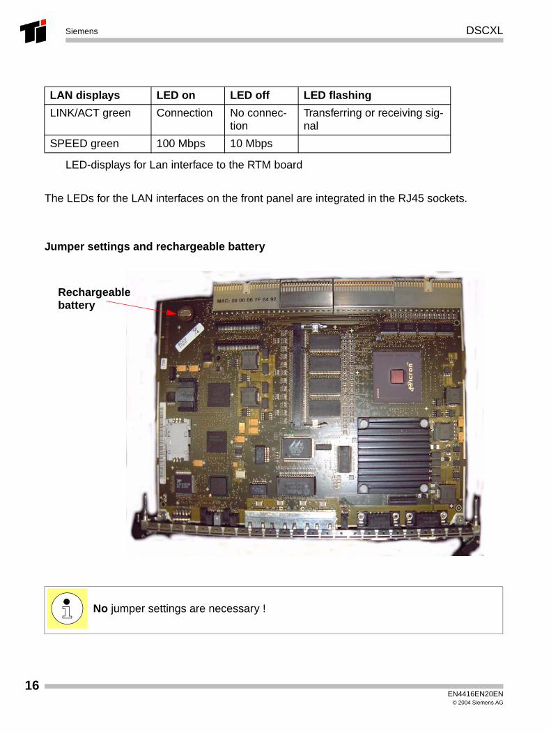
LED-displays for Lan interface to the RTM board
The LEDs for the LAN interfaces on the front panel are integrated in the RJ45 sockets.
Jumper settings and rechargeable battery
LAN displays LED on LED off LED flashing
LINK/ACT green Connection No connec-tion
Transferring or receiving sig-nal
SPEED green 100 Mbps 10 Mbps
No jumper settings are necessary !
Rechargeablebattery
EN4416EN20EN© 2004 Siemens AG
DSCXL Siemens
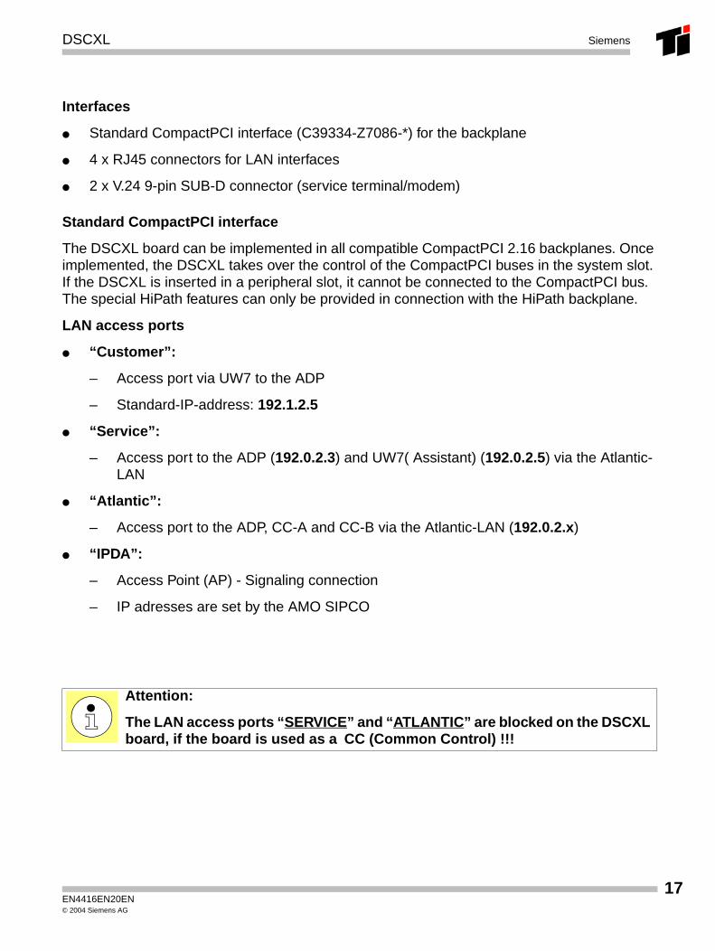
Interfaces
● Standard CompactPCI interface (C39334-Z7086-*) for the backplane
● 4 x RJ45 connectors for LAN interfaces
● 2 x V.24 9-pin SUB-D connector (service terminal/modem)
Standard CompactPCI interface
The DSCXL board can be implemented in all compatible CompactPCI 2.16 backplanes. Once implemented, the DSCXL takes over the control of the CompactPCI buses in the system slot. If the DSCXL is inserted in a peripheral slot, it cannot be connected to the CompactPCI bus.The special HiPath features can only be provided in connection with the HiPath backplane.
LAN access ports
● “Customer”:
– Access port via UW7 to the ADP
– Standard-IP-address: 192.1.2.5
● “Service”:
– Access port to the ADP (192.0.2.3) and UW7( Assistant) (192.0.2.5) via the Atlantic-LAN
● “Atlantic”:
– Access port to the ADP, CC-A and CC-B via the Atlantic-LAN (192.0.2.x)
● “IPDA”:
– Access Point (AP) - Signaling connection
– IP adresses are set by the AMO SIPCO
Attention:
The LAN access ports “SERVICE” and “ATLANTIC” are blocked on the DSCXL board, if the board is used as a CC (Common Control) !!!
EN4416EN20EN© 2004 Siemens AG
17
18
DSCXLSiemens
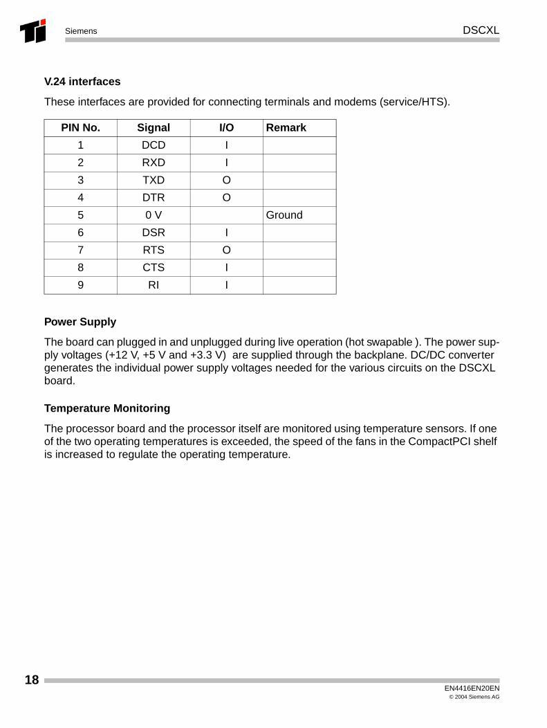
V.24 interfaces
These interfaces are provided for connecting terminals and modems (service/HTS).
Power Supply
The board can plugged in and unplugged during live operation (hot swapable ). The power sup-ply voltages (+12 V, +5 V and +3.3 V) are supplied through the backplane. DC/DC converter generates the individual power supply voltages needed for the various circuits on the DSCXL board.
Temperature Monitoring
The processor board and the processor itself are monitored using temperature sensors. If one of the two operating temperatures is exceeded, the speed of the fans in the CompactPCI shelf is increased to regulate the operating temperature.
PIN No. Signal I/O Remark
1 DCD I
2 RXD I
3 TXD O
4 DTR O
5 0 V Ground
6 DSR I
7 RTS O
8 CTS I
9 RI I
EN4416EN20EN© 2004 Siemens AG
DSCXL Siemens
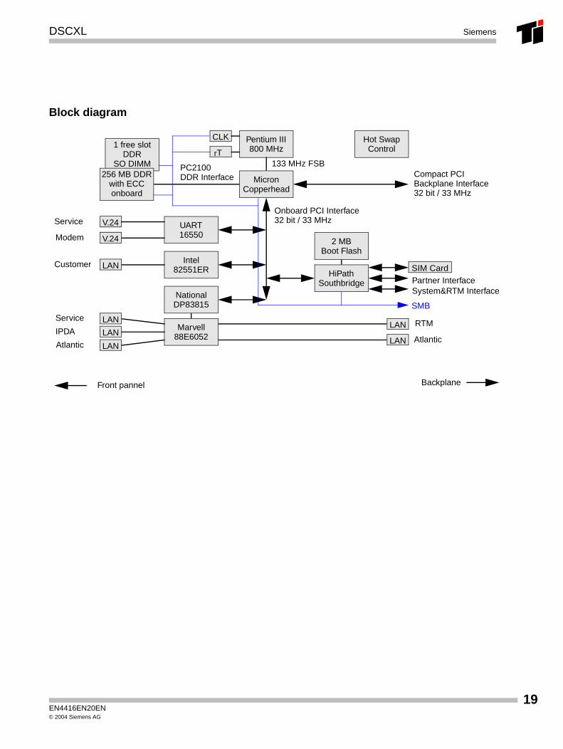
Block diagram
SIM Card
PC2100DDR Interface
133 MHz FSB
Service
Modem
Customer
Service
IPDA
Atlantic
RTM
Atlantic
Onboard PCI Interface32 bit / 33 MHz
BackplaneFront pannel
Pentium III800 MHz
MicronCopperhead
CLK
rT1 free slot
DDRSO DIMM
256 MB DDRwith ECConboard
Compact PCIBackplane Interface32 bit / 33 MHz
UART16550
V.24
V.24
Intel82551ERLAN
NationalDP83815
Marvell88E6052LAN
LAN
LAN
2 MBBoot Flash
HiPathSouthbridge
LAN
LAN
Partner InterfaceSystem&RTM Interface
SMB
Hot SwapControl
EN4416EN20EN© 2004 Siemens AG
19

20
DSCXLSiemens
EN4416EN20EN© 2004 Siemens AG
HDMO Siemens
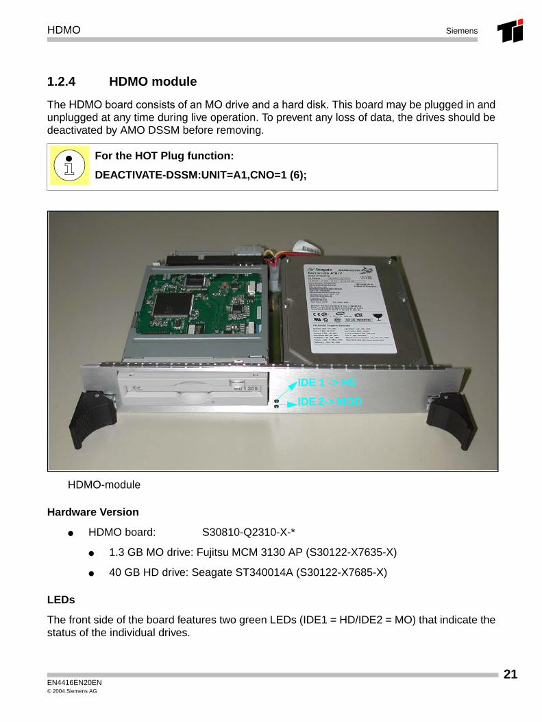
1.2.4 HDMO module
The HDMO board consists of an MO drive and a hard disk. This board may be plugged in and unplugged at any time during live operation. To prevent any loss of data, the drives should be deactivated by AMO DSSM before removing.
HDMO-module
Hardware Version
● HDMO board: S30810-Q2310-X-*
● 1.3 GB MO drive: Fujitsu MCM 3130 AP (S30122-X7635-X)
● 40 GB HD drive: Seagate ST340014A (S30122-X7685-X)
LEDs
The front side of the board features two green LEDs (IDE1 = HD/IDE2 = MO) that indicate the status of the individual drives.
For the HOT Plug function:
DEACTIVATE-DSSM:UNIT=A1,CNO=1 (6);
IDE 1 -> HD
IDE 2-> MOD
EN4416EN20EN© 2004 Siemens AG
21
22
HDMOSiemens
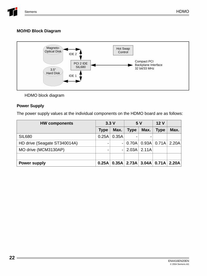
MO/HD Block Diagram
HDMO block diagram
Power Supply
The power supply values at the individual components on the HDMO board are as follows:
HW components 3.3 V 5 V 12 V
Type Max. Type Max. Type Max.
SIL680 0.25A 0.35A - -
HD drive (Seagate ST340014A) - - 0.70A 0.93A 0.71A 2.20A
MO drive (MCM3130AP) - - 2.03A 2.11A
Power supply 0.25A 0.35A 2.73A 3.04A 0.71A 2.20A
PCI 2 IDESIL680
Compact PCIBackplane Interface32 bit/33 MHz
IDE 2
Hot SwapControl
3.5”Hard Disk
Magneto-Optical Disk
IDE 1
EN4416EN20EN© 2004 Siemens AG
HDMO Siemens
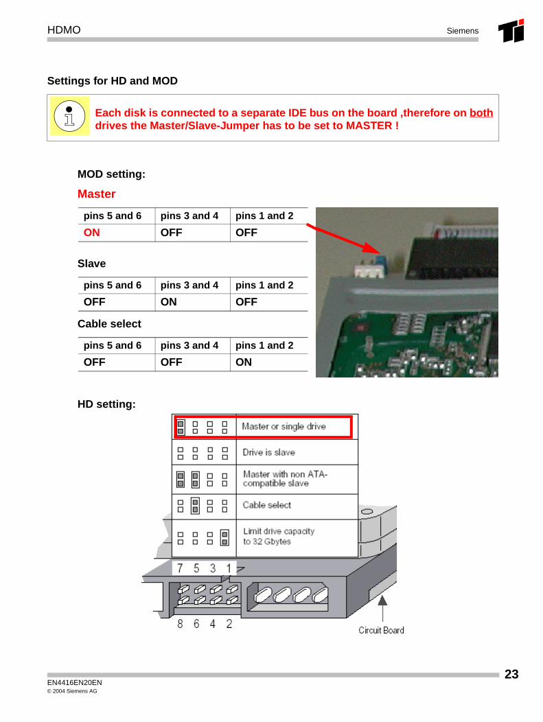
Settings for HD and MOD
MOD setting:
Master
Slave
Cable select
HD setting:
Each disk is connected to a separate IDE bus on the board ,therefore on both drives the Master/Slave-Jumper has to be set to MASTER !
pins 5 and 6 pins 3 and 4 pins 1 and 2
ON OFF OFF
pins 5 and 6 pins 3 and 4 pins 1 and 2
OFF ON OFF
pins 5 and 6 pins 3 and 4 pins 1 and 2
OFF OFF ON
EN4416EN20EN© 2004 Siemens AG
23
24
HDMOSiemens
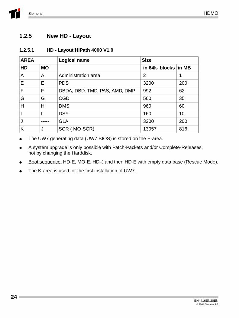
1.2.5 New HD - Layout
1.2.5.1 HD - Layout HiPath 4000 V1.0
● The UW7 generating data (UW7 BIOS) is stored on the E-area.
● A system upgrade is only possible with Patch-Packets and/or Complete-Releases, not by changing the Harddisk.
● Boot sequence: HD-E, MO-E, HD-J and then HD-E with empty data base (Rescue Mode).
● The K-area is used for the first installation of UW7.
AREA Logical name Size
HD MO in 64k- blocks in MB
A A Administration area 2 1
E E PDS 3200 200
F F DBDA, DBD, TMD, PAS, AMD, DMP 992 62
G G CGD 560 35
H H DMS 960 60
I I DSY 160 10
J ----- GLA 3200 200
K J SCR ( MO-SCR) 13057 816
EN4416EN20EN© 2004 Siemens AG
HDMO Siemens
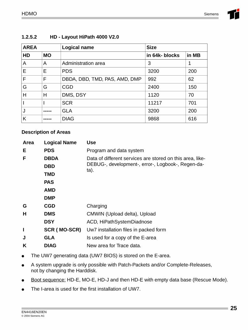
1.2.5.2 HD - Layout HiPath 4000 V2.0
Description of Areas
● The UW7 generating data (UW7 BIOS) is stored on the E-area.
● A system upgrade is only possible with Patch-Packets and/or Complete-Releases, not by changing the Harddisk.
● Boot sequence: HD-E, MO-E, HD-J and then HD-E with empty data base (Rescue Mode).
● The I-area is used for the first installation of UW7.
AREA Logical name Size
HD MO in 64k- blocks in MB
A A Administration area 3 1
E E PDS 3200 200
F F DBDA, DBD, TMD, PAS, AMD, DMP 992 62
G G CGD 2400 150
H H DMS, DSY 1120 70
I I SCR 11217 701
J ----- GLA 3200 200
K ----- DIAG 9868 616
Area Logical Name Use
E PDS Program and data system
F DBDA Data of different services are stored on this area, like-DEBUG-, development-, error-, Logbook-, Regen-da-ta).
DBD
TMD
PAS
AMD
DMP
G CGD Charging
H DMS CMWIN (Upload delta), Upload
DSY ACD, HiPathSystemDiadnose
I SCR ( MO-SCR) Uw7 installation files in packed form
J GLA Is used for a copy of the E-area
K DIAG New area for Trace data.
EN4416EN20EN© 2004 Siemens AG
25

26
HDMOSiemens
EN4416EN20EN© 2004 Siemens AG
SF2X8 Siemens
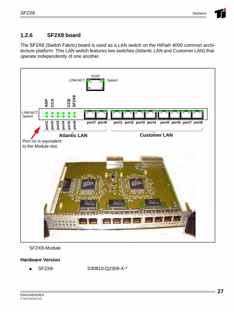
1.2.6 SF2X8 board
The SF2X8 (Switch Fabric) board is used as a LAN switch on the HiPath 4000 common archi-tecture platform. This LAN switch features two switches (Atlantic LAN and Customer LAN) that operate independently of one another.
SF2X8-Module
Hardware Version
● SF2X8: S30810-Q2309-X-*
SpeedLINK/ACTRJ45
port8port7port6port5port4port3port2port1port8
po
rt6
po
rt5
po
rt4
po
rt3
po
rt2
po
rt1 port7
Atlantic LAN Customer LAN
LINK/ACTSpeed
8 1
CC
A
AD
P
CC
BS
F2X
8
Port no is equivalent to the Module-slot.
EN4416EN20EN© 2004 Siemens AG
27
28
SF2X8Siemens
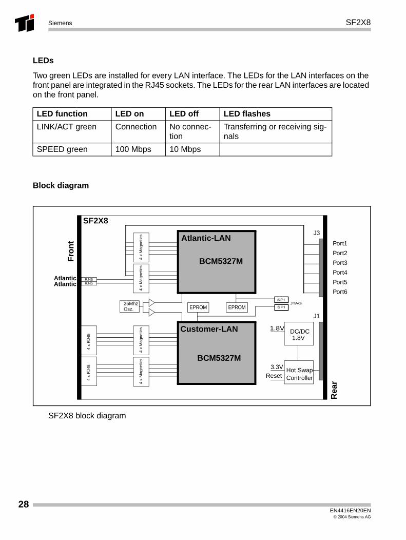
LEDs
Two green LEDs are installed for every LAN interface. The LEDs for the LAN interfaces on the front panel are integrated in the RJ45 sockets. The LEDs for the rear LAN interfaces are located on the front panel.
Block diagram
SF2X8 block diagram
LED function LED on LED off LED flashes
LINK/ACT green Connection No connec-tion
Transferring or receiving sig-nals
SPEED green 100 Mbps 10 Mbps
BCM5327M
BCM5327MHot SwapController
DC/DC1.8V
4 x
Mag
netic
s
RJ45
1.8V
3.3V
SF2X8
Fro
nt
Rea
r
Atlantic 1
Port1
Port2
Port3
Port4
Port5
Port6Atlantic 2
Atlantic-LAN
Customer-LAN
EPROMEPROM25MhzOsz.
4 x
Mag
netic
s4
x M
agne
tics
4 x
Mag
netic
s
SPI
SPI
4 x
RJ4
54
x R
J45
RJ45
Reset
J1
J3
JTAG
EN4416EN20EN© 2004 Siemens AG
SF2X8 Siemens
Interfaces
● Atlantic LAN
The Atlantic LAN switch supports two external Ethernet interfaces on the front panel and six internal Ethernet interfaces on the back of the board. These are connected to the CSPCI back-plane over the J3 connector.
● Customer LAN
The customer LAN supports eight external Ethernet interfaces on the front panel. It has the function of a not programmable Layer2 switch with 8 Ethernet interfaces for 10/100 Mbit/sec.
Power Supply
The SF2X8 board receives +3.3 V from the system’s backplane over the J1 connector. The 1.8-V power supply voltage required for the LAN circuits on the SF2X8 board is generated by the DC/DC converter.
A "Hot Swap Controller" monitors the voltage levels (surge protection) and disables the board in the event of overvoltage or undervoltage. The board is reset after being disabled.
> The SF2X8 board can plugged in and unplugged during live operation..
EN4416EN20EN© 2004 Siemens AG
29

30
SF2X8Siemens
EN4416EN20EN© 2004 Siemens AG
MCM Siemens
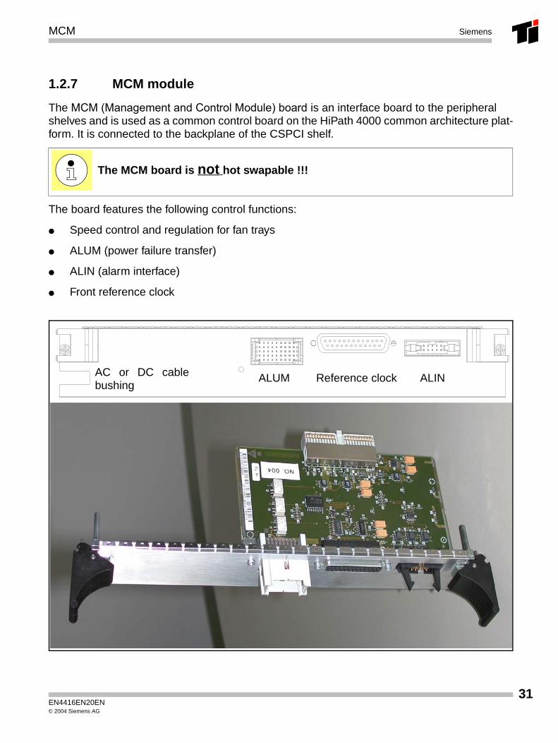
1.2.7 MCM module
The MCM (Management and Control Module) board is an interface board to the peripheral shelves and is used as a common control board on the HiPath 4000 common architecture plat-form. It is connected to the backplane of the CSPCI shelf.
The board features the following control functions:
● Speed control and regulation for fan trays
● ALUM (power failure transfer)
● ALIN (alarm interface)
● Front reference clock
The MCM board is not hot swapable !!!
ALUM Reference clock ALINAC or DC cablebushing
EN4416EN20EN© 2004 Siemens AG
31
32
MCMSiemens
Hardware Version
– MCM: S30810-Q2313-X-*
Interfaces
● ALUM (power failure transfer)
● ALIN (alarm interface)
● Front reference clock
● Backplane
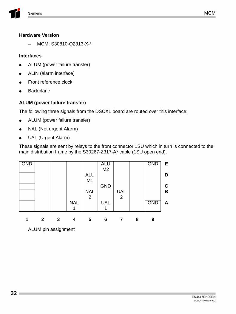
ALUM (power failure transfer)
The following three signals from the DSCXL board are routed over this interface:
● ALUM (power failure transfer)
● NAL (Not urgent Alarm)
● UAL (Urgent Alarm)
These signals are sent by relays to the front connector 1SU which in turn is connected to the main distribution frame by the S30267-Z317-A* cable (1SU open end).
ALUM pin assignment
GND ALUM2
GND E
ALUM1
D
GND CNAL
2UAL
2B
NAL1
UAL1
GND A
1 2 3 4 5 6 7 8 9
EN4416EN20EN© 2004 Siemens AG
MCM Siemens
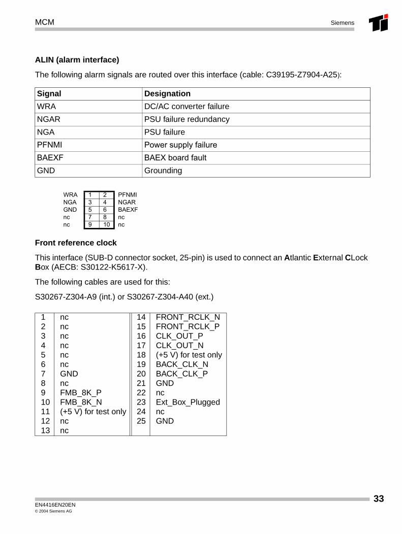
ALIN (alarm interface)
The following alarm signals are routed over this interface (cable: C39195-Z7904-A25):
Front reference clock
This interface (SUB-D connector socket, 25-pin) is used to connect an Atlantic External CLock Box (AECB: S30122-K5617-X).
The following cables are used for this:
S30267-Z304-A9 (int.) or S30267-Z304-A40 (ext.)
Signal Designation
WRA DC/AC converter failure
NGAR PSU failure redundancy
NGA PSU failure
PFNMI Power supply failure BAEXF BAEX board faultGND Grounding
WRA 1 2 PFNMINGA 3 4 NGARGND 5 6 BAEXFnc 7 8 ncnc 9 10 nc
1 nc 14 FRONT_RCLK_N2 nc 15 FRONT_RCLK_P3 nc 16 CLK_OUT_P4 nc 17 CLK_OUT_N5 nc 18 (+5 V) for test only6 nc 19 BACK_CLK_N7 GND 20 BACK_CLK_P8 nc 21 GND9 FMB_8K_P 22 nc10 FMB_8K_N 23 Ext_Box_Plugged11 (+5 V) for test only 24 nc12 nc 25 GND13 nc
EN4416EN20EN© 2004 Siemens AG
33
34
MCMSiemens
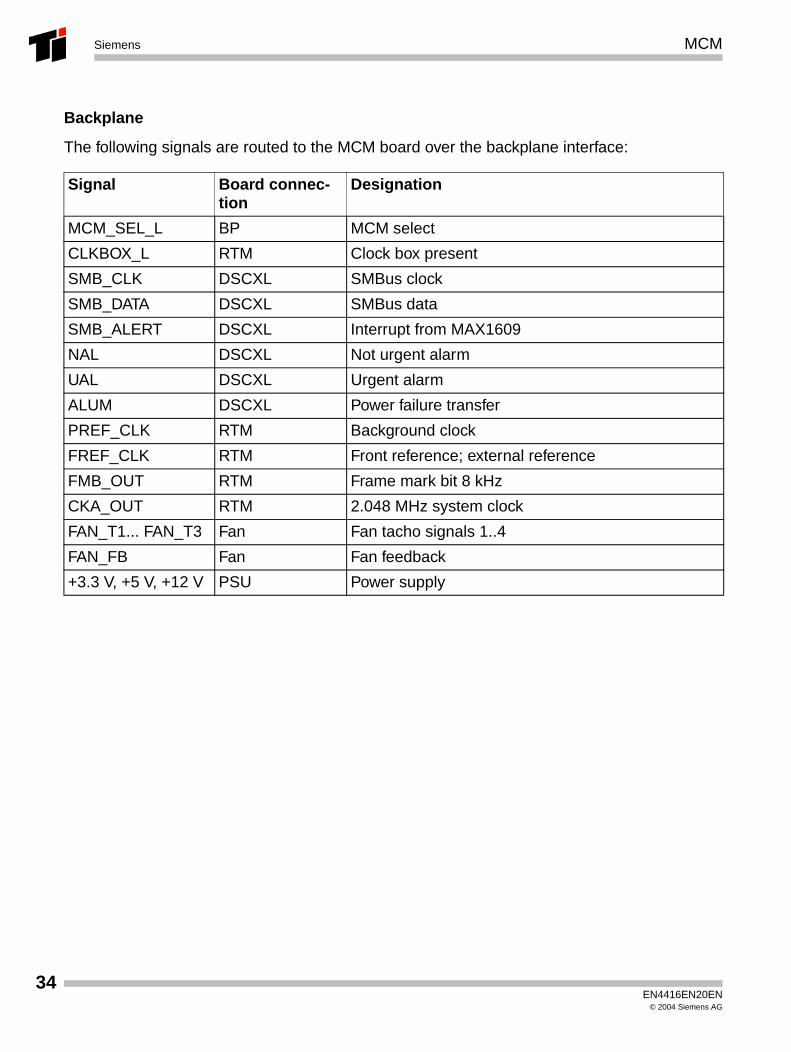
Backplane
The following signals are routed to the MCM board over the backplane interface:
Signal Board connec-tion
Designation
MCM_SEL_L BP MCM select
CLKBOX_L RTM Clock box present
SMB_CLK DSCXL SMBus clock
SMB_DATA DSCXL SMBus data
SMB_ALERT DSCXL Interrupt from MAX1609
NAL DSCXL Not urgent alarm
UAL DSCXL Urgent alarm
ALUM DSCXL Power failure transfer
PREF_CLK RTM Background clock
FREF_CLK RTM Front reference; external reference
FMB_OUT RTM Frame mark bit 8 kHz
CKA_OUT RTM 2.048 MHz system clock
FAN_T1... FAN_T3 Fan Fan tacho signals 1..4
FAN_FB Fan Fan feedback
+3.3 V, +5 V, +12 V PSU Power supply
EN4416EN20EN© 2004 Siemens AG
RTM Siemens
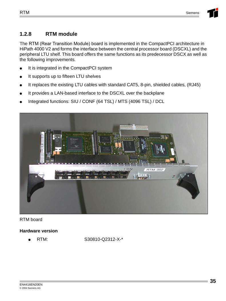
1.2.8 RTM module
The RTM (Rear Transition Module) board is implemented in the CompactPCI architecture in HiPath 4000 V2 and forms the interface between the central processor board (DSCXL) and the peripheral LTU shelf. This board offers the same functions as its predecessor DSCX as well as the following improvements.
● It is integrated in the CompactPCI system
● It supports up to fifteen LTU shelves
● It replaces the existing LTU cables with standard CAT5, 8-pin, shielded cables, (RJ45)
● It provides a LAN-based interface to the DSCXL over the backplane
● Integrated functions: SIU / CONF (64 TSL) / MTS (4096 TSL) / DCL
RTM board
Hardware version
● RTM: S30810-Q2312-X-*
EN4416EN20EN© 2004 Siemens AG
35
36
RTMSiemens
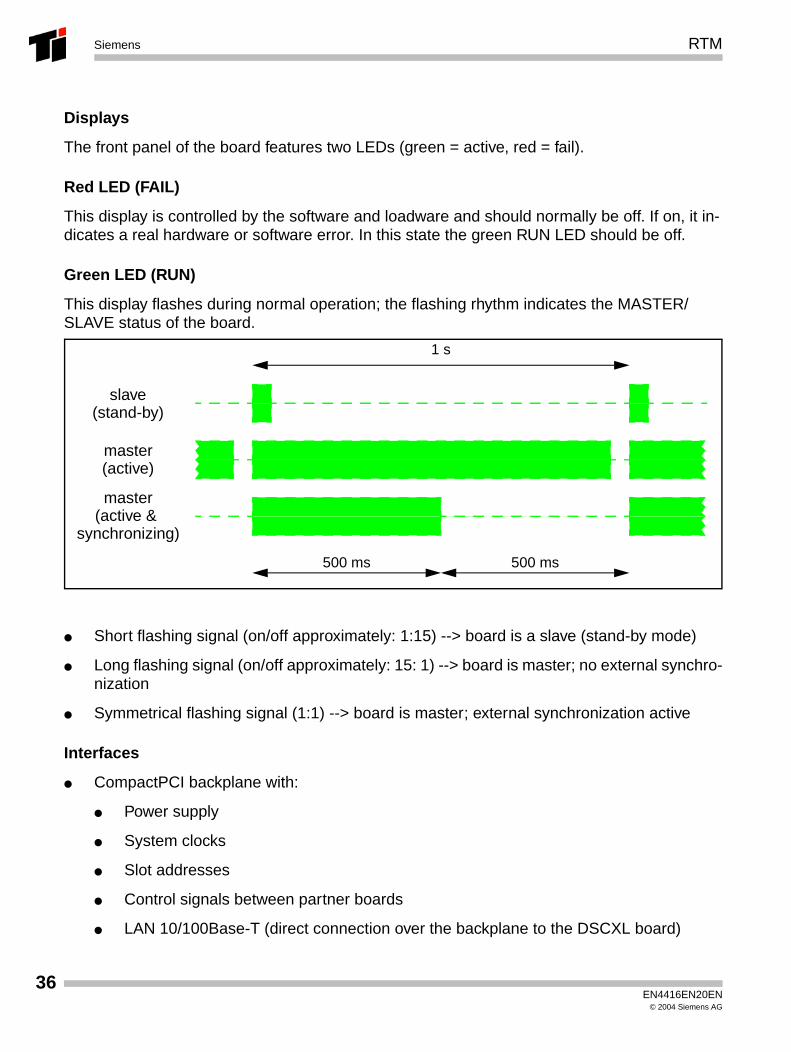
Displays
The front panel of the board features two LEDs (green = active, red = fail).
Red LED (FAIL)
This display is controlled by the software and loadware and should normally be off. If on, it in-dicates a real hardware or software error. In this state the green RUN LED should be off.
Green LED (RUN)
This display flashes during normal operation; the flashing rhythm indicates the MASTER/SLAVE status of the board.
● Short flashing signal (on/off approximately: 1:15) --> board is a slave (stand-by mode)
● Long flashing signal (on/off approximately: 15: 1) --> board is master; no external synchro-nization
● Symmetrical flashing signal (1:1) --> board is master; external synchronization active
Interfaces
● CompactPCI backplane with:
● Power supply
● System clocks
● Slot addresses
● Control signals between partner boards
● LAN 10/100Base-T (direct connection over the backplane to the DSCXL board)
master
1 s
500 ms
master
500 ms
slave
(active &
(stand-by)
(active)
synchronizing)
EN4416EN20EN© 2004 Siemens AG
RTM Siemens
● LTU 15 x RJ45 each with 32 Mbps (each of which has 1x HDLC channel with 2 Mbps and 4x PCM64s (256 Timeslot per LTU, max. 3840 Timeslot)
● V.24 9-pin SUB-D connector (service connector)
● Displays (LED)
CPCI - Backplane
The 3.3-V power supply is routed over this interface, the system clocks are distributed and the slot addresses are read. In a duplex system, at least two RTM boards are implemented and are connected to each other by a partner interface and communicate with the appropriate DSCXL processor board over the backplane. The DSCXL board can determine the status of the RTM hardware or firmware on the basis of signals. The RTM can also recognize the status of the DSCXL boards.
A 10/100Base-T Ethernet connection to the DSCXL is also provided over the backplane.
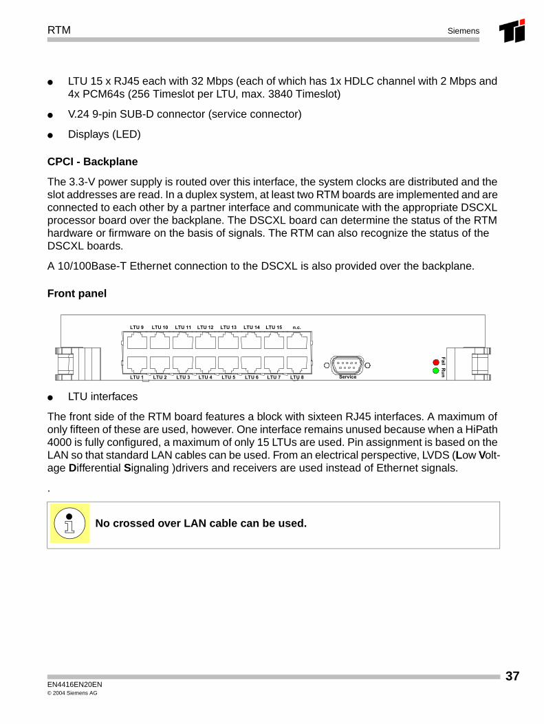
Front panel
● LTU interfaces
The front side of the RTM board features a block with sixteen RJ45 interfaces. A maximum of only fifteen of these are used, however. One interface remains unused because when a HiPath 4000 is fully configured, a maximum of only 15 LTUs are used. Pin assignment is based on the LAN so that standard LAN cables can be used. From an electrical perspective, LVDS (Low Volt-age Differential Signaling )drivers and receivers are used instead of Ethernet signals.
.
No crossed over LAN cable can be used.
Fail Run
LTU 1 LTU 2 LTU 3 LTU 4 LTU 5 LTU 6 LTU 7 LTU 8
LTU 9 LTU 10 LTU 11 LTU 12 LTU 13 LTU 14 LTU 15 n.c.
Service
EN4416EN20EN© 2004 Siemens AG
37
38
RTMSiemens
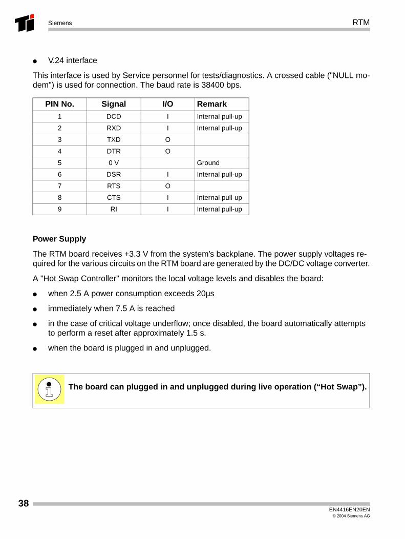
● V.24 interface
This interface is used by Service personnel for tests/diagnostics. A crossed cable ("NULL mo-dem") is used for connection. The baud rate is 38400 bps.
Power Supply
The RTM board receives +3.3 V from the system’s backplane. The power supply voltages re-quired for the various circuits on the RTM board are generated by the DC/DC voltage converter.
A "Hot Swap Controller" monitors the local voltage levels and disables the board:
● when 2.5 A power consumption exceeds 20µs
● immediately when 7.5 A is reached
● in the case of critical voltage underflow; once disabled, the board automatically attempts to perform a reset after approximately 1.5 s.
● when the board is plugged in and unplugged.
PIN No. Signal I/O Remark1 DCD I Internal pull-up
2 RXD I Internal pull-up
3 TXD O
4 DTR O
5 0 V Ground
6 DSR I Internal pull-up
7 RTS O
8 CTS I Internal pull-up
9 RI I Internal pull-up
The board can plugged in and unplugged during live operation (“Hot Swap”).
EN4416EN20EN© 2004 Siemens AG
RTM Siemens
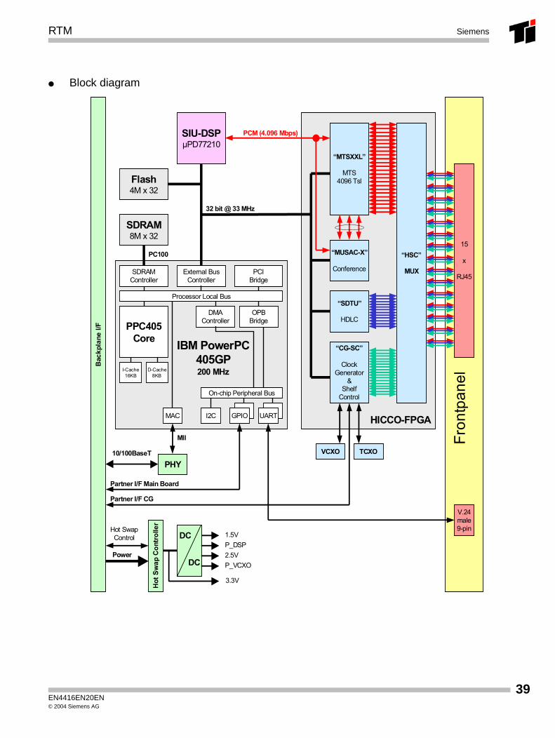
● Block diagram
Fron
tpan
el
.
External BusController
PPC405Core
On-chip Peripheral Bus
I2C
Processor Local Bus
SDRAMController
PCIBridge
GPIO
DMAController
MAC
OPBBridge
I-Cache16KB
D-Cache8KB
IBM PowerPC405GP200 MHz
UART
Flash4M x 32
SDRAM8M x 32
PC100
PHY
MII
V.24male9-pin
HICCO-FPGA
RTM Block Diagram11.09.2002ICN EN HC ID 34Lars Rostock
10/100BaseT
PCM (4.096 Mbps)
“MTSXXL”
MTS4096 Tsl
“MUSAC-X”
Conference
“CG-SC”
ClockGenerator
&Shelf
Control
SIU-DSPµPD77210
Bac
kpla
ne I/
F
Power
1.5VDC
DC
3.3V
Hot
Sw
ap C
ontr
olle
r
Hot SwapControl
“SDTU”
HDLC
“HSC”
MUX
15
x
RJ45
VCXO TCXO
Partner I/F CG
Partner I/F Main Board
P_DSP2.5VP_VCXO
32 bit @ 33 MHz
EN4416EN20EN© 2004 Siemens AG
39
40
RTMSiemens
AMO changes:
New loading of all RTM modules:
ACTIVATE-USSU:UNIT=RTM,TYPE=BOARD;
New loading of the active RTM module (Duplex):
ACTIVATE-USSU:UNIT=RTM,TYPE=DATA;
EN4416EN20EN© 2004 Siemens AG
ACPCI/DCPCI Siemens
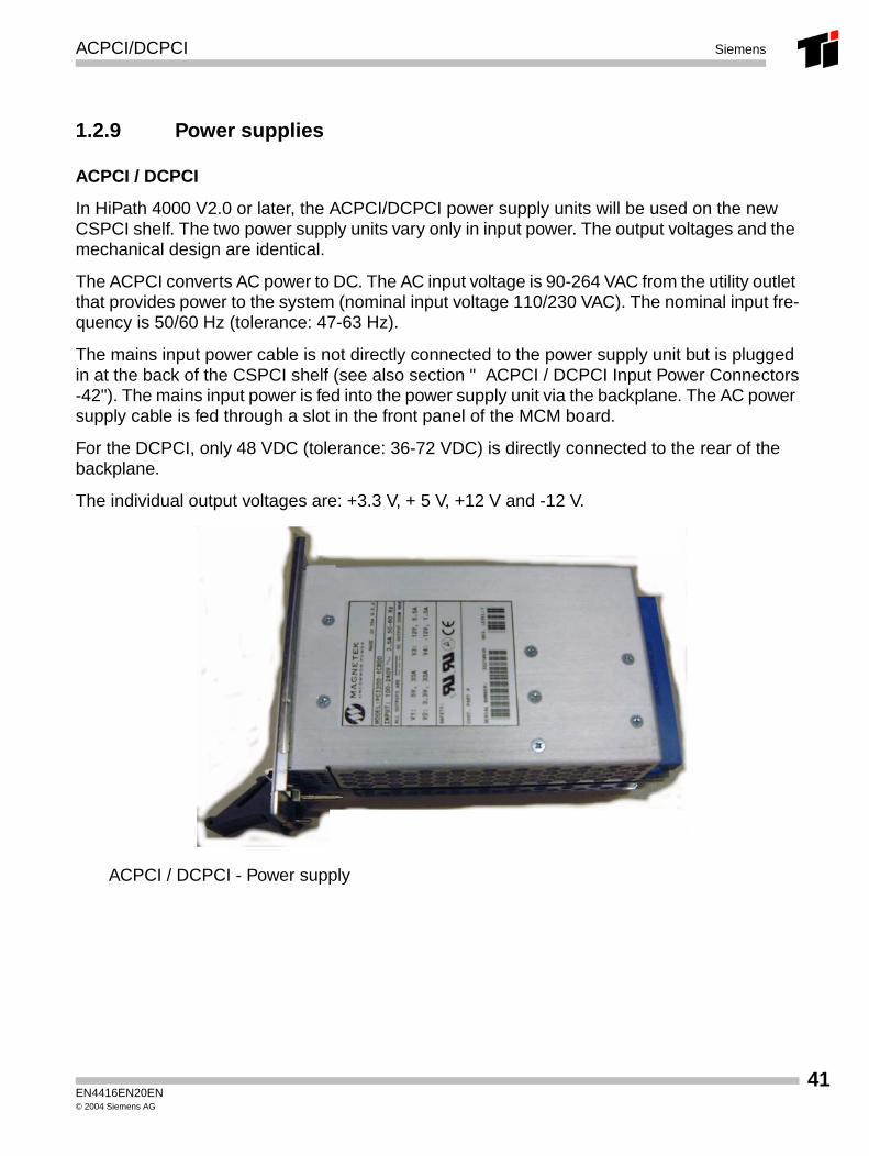
1.2.9 Power supplies
ACPCI / DCPCI
In HiPath 4000 V2.0 or later, the ACPCI/DCPCI power supply units will be used on the new CSPCI shelf. The two power supply units vary only in input power. The output voltages and the mechanical design are identical.
The ACPCI converts AC power to DC. The AC input voltage is 90-264 VAC from the utility outlet that provides power to the system (nominal input voltage 110/230 VAC). The nominal input fre-quency is 50/60 Hz (tolerance: 47-63 Hz).
The mains input power cable is not directly connected to the power supply unit but is plugged in at the back of the CSPCI shelf (see also section " ACPCI / DCPCI Input Power Connectors-42"). The mains input power is fed into the power supply unit via the backplane. The AC power supply cable is fed through a slot in the front panel of the MCM board.
For the DCPCI, only 48 VDC (tolerance: 36-72 VDC) is directly connected to the rear of the backplane.
The individual output voltages are: +3.3 V, + 5 V, +12 V and -12 V.
ACPCI / DCPCI - Power supply
EN4416EN20EN© 2004 Siemens AG
41
42
ACPCI/DCPCISiemens
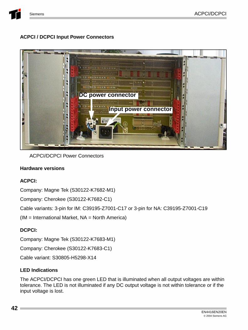
ACPCI / DCPCI Input Power Connectors
ACPCI/DCPCI Power Connectors
Hardware versions
ACPCI:
Company: Magne Tek (S30122-K7682-M1)
Company: Cherokee (S30122-K7682-C1)
Cable variants: 3-pin for IM: C39195-Z7001-C17 or 3-pin for NA: C39195-Z7001-C19
(IM = International Market, NA = North America)
DCPCI:
Company: Magne Tek (S30122-K7683-M1)
Company: Cherokee (S30122-K7683-C1)
Cable variant: S30805-H5298-X14
LED Indications
The ACPCI/DCPCI has one green LED that is illuminated when all output voltages are within tolerance. The LED is not illuminated if any DC output voltage is not within tolerance or if the input voltage is lost.
Input power connector
DC power connector
EN4416EN20EN© 2004 Siemens AG
ACPCI/DCPCI Siemens
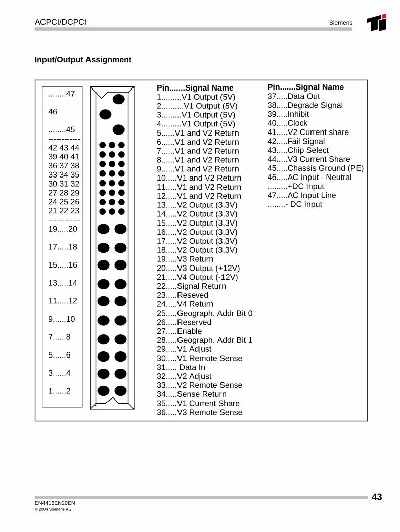
Input/Output Assignment
........47
46
........45------------42 43 4439 40 4136 37 3833 34 3530 31 3227 28 2924 25 2621 22 23------------19.....20
17.....18
15.....16
13.....14
11.....12
9......10
7......8
5......6
3......4
1......2
Pin.......Signal Name1.........V1 Output (5V)2..........V1 Output (5V)3.........V1 Output (5V)4.........V1 Output (5V)5......V1 and V2 Return6......V1 and V2 Return7......V1 and V2 Return8......V1 and V2 Return9......V1 and V2 Return10.....V1 and V2 Return11.....V1 and V2 Return12.....V1 and V2 Return13.....V2 Output (3,3V)14.....V2 Output (3,3V)15.....V2 Output (3,3V)16.....V2 Output (3,3V)17.....V2 Output (3,3V)18.....V2 Output (3,3V)19.....V3 Return20.....V3 Output (+12V)21.....V4 Output (-12V)22.....Signal Return23.....Reseved24.....V4 Return25.....Geograph. Addr Bit 026.....Reserved27.....Enable28.....Geograph. Addr Bit 129.....V1 Adjust30.....V1 Remote Sense31..... Data In32.....V2 Adjust33.....V2 Remote Sense34.....Sense Return35.....V1 Current Share36.....V3 Remote Sense
Pin.......Signal Name37.....Data Out38.....Degrade Signal39.....Inhibit40.....Clock41.....V2 Current share42.....Fail Signal43.....Chip Select44.....V3 Current Share45.....Chassis Ground (PE)46.....AC Input - Neutral.........+DC Input47.....AC Input Line........- DC Input
EN4416EN20EN© 2004 Siemens AG
43
44
Fan TraySiemens
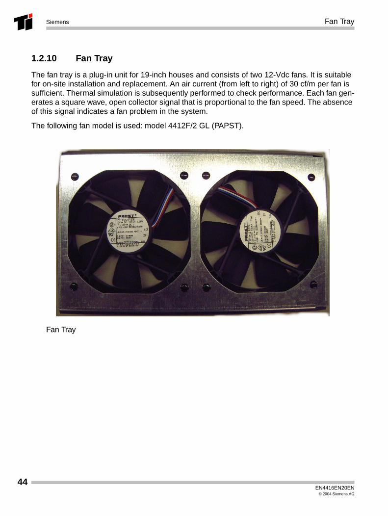
1.2.10 Fan Tray
The fan tray is a plug-in unit for 19-inch houses and consists of two 12-Vdc fans. It is suitable for on-site installation and replacement. An air current (from left to right) of 30 cf/m per fan is sufficient. Thermal simulation is subsequently performed to check performance. Each fan gen-erates a square wave, open collector signal that is proportional to the fan speed. The absence of this signal indicates a fan problem in the system.
The following fan model is used: model 4412F/2 GL (PAPST).
Fan Tray
EN4416EN20EN© 2004 Siemens AG
Fan Tray Siemens
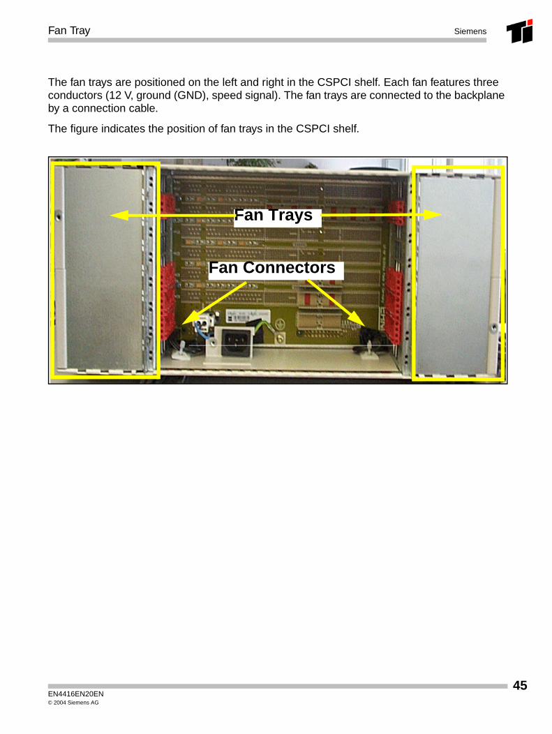
The fan trays are positioned on the left and right in the CSPCI shelf. Each fan features three conductors (12 V, ground (GND), speed signal). The fan trays are connected to the backplane by a connection cable.
The figure indicates the position of fan trays in the CSPCI shelf.
Fan Trays
Fan Connectors
EN4416EN20EN© 2004 Siemens AG
45
46
Fan TraySiemens
EN4416EN20EN© 2004 Siemens AG
LTU - AP 3700 SAPP Siemens
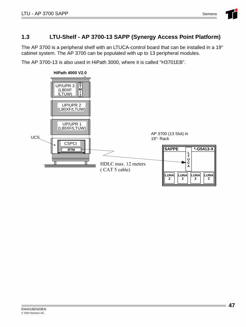
1.3 LTU-Shelf - AP 3700-13 SAPP (Synergy Access Point Platform)
The AP 3700 is a peripheral shelf with an LTUCA-control board that can be installed in a 19" cabinet system. The AP 3700 can be populated with up to 13 peripheral modules.
The AP 3700-13 is also used in HiPath 3000, where it is called "H3701EB".
SAPPE *-G5413-X
LUNA2
LUNA2
LUNA2
LUNA2
AP 3700 (13 Slot) in19"- Rack
LTUCA
HiPath 4000 V2.0
UP/UPR 1(L80XF/LTUW)
UP/UPR 2(L80XF/LTUW)
UCS
UP/UPR 3(L80XF/LTUW)
STMI2
RTM
CSPCI
HDLC max. 12 meters( CAT 5 cable)
EN4416EN20EN© 2004 Siemens AG
47
48
LTU - AP 3700 SAPPSiemens
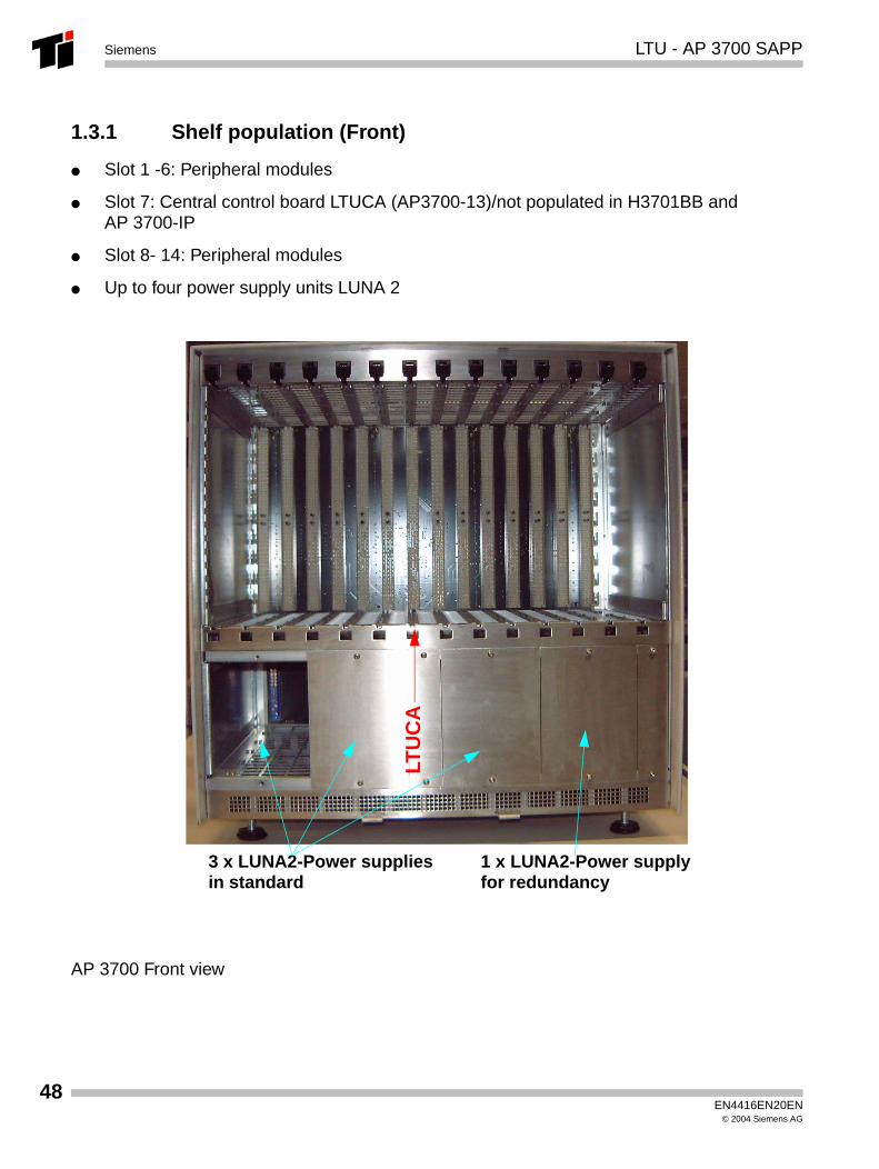
1.3.1 Shelf population (Front)
● Slot 1 -6: Peripheral modules
● Slot 7: Central control board LTUCA (AP3700-13)/not populated in H3701BB and AP 3700-IP
● Slot 8- 14: Peripheral modules
● Up to four power supply units LUNA 2
AP 3700 Front view
LTU
CA
3 x LUNA2-Power suppliesin standard
1 x LUNA2-Power supplyfor redundancy
EN4416EN20EN© 2004 Siemens AG
LTU - AP 3700 SAPP Siemens
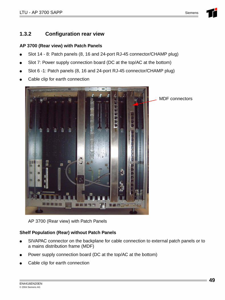
1.3.2 Configuration rear view
AP 3700 (Rear view) with Patch Panels
● Slot 14 - 8: Patch panels (8, 16 and 24-port RJ-45 connector/CHAMP plug)
● Slot 7: Power supply connection board (DC at the top/AC at the bottom)
● Slot 6 -1: Patch panels (8, 16 and 24-port RJ-45 connector/CHAMP plug)
● Cable clip for earth connection
AP 3700 (Rear view) with Patch Panels
Shelf Population (Rear) without Patch Panels
● SIVAPAC connector on the backplane for cable connection to external patch panels or to a mains distribution frame (MDF)
● Power supply connection board (DC at the top/AC at the bottom)
● Cable clip for earth connection
MDF connectors
EN4416EN20EN© 2004 Siemens AG
49
50
LTU - AP 3700 SAPPSiemens
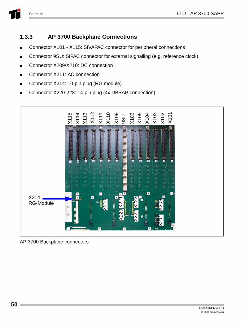
1.3.3 AP 3700 Backplane Connections
● Connector X101 - X115: SIVAPAC connector for peripheral connections
● Connector 9SU: SIPAC connector for external signalling (e.g. reference clock)
● Connector X209/X210: DC connection
● Connector X211: AC connection
● Connector X214: 10-pin plug (RG module)
● Connector X220-223: 14-pin plug (4x DBSAP connection)
AP 3700 Backplane connectors
X10
1
X10
2
X10
3
X10
4
X10
5
9SU
X10
9
X11
0
X11
1
X11
2
X22
2
X21
1X
209
X22
3X214RG-Module
X10
6
X11
3
X11
4
X11
5
X21
0
X22
1X
220
EN4416EN20EN© 2004 Siemens AG
LTU - AP 3700 SAPP Siemens
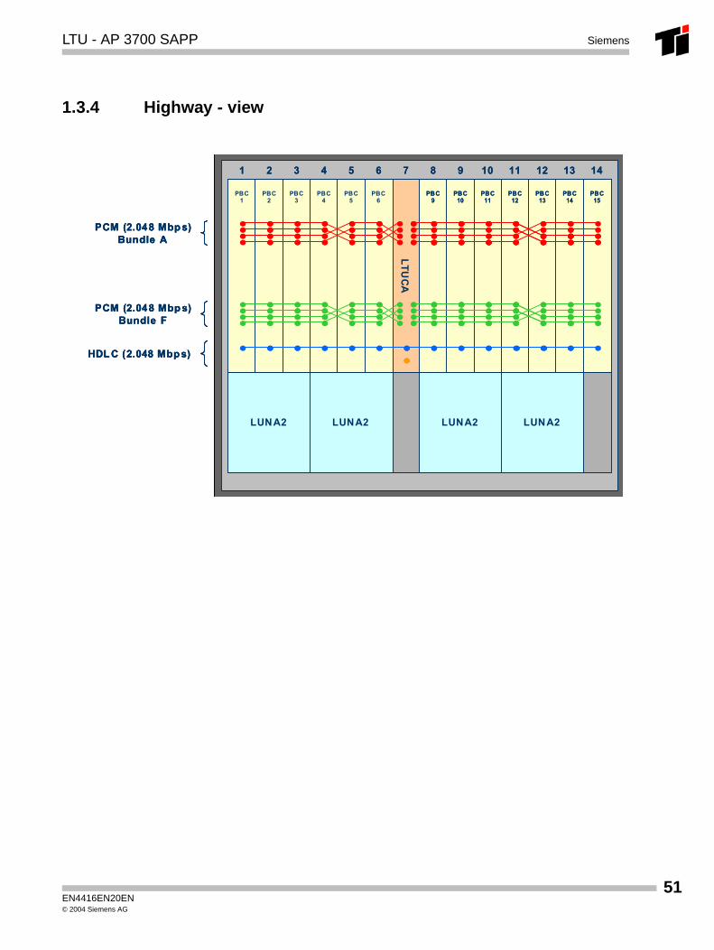
1.3.4 Highway - view
LTUCA
PBC1
PBC2
PBC3
PBC4
PBC5
PCM (2.048 Mbp s)Bundle A
PCM (2.048 Mbp s)Bundle F
1 2 3 4 5 6 7 8 9 10 11 12 13 14
PBC9
PBC10
PBC11
PBC12
PBC13
PBC14
PBC15
PBC6
LUNA2 LUNA2LUNA2 LUNA2
HDL C (2.048 Mbp s)
LTUCA
PBC1
PBC2
PBC3
PBC4
PBC5
PCM (2.048 Mbp s)Bundle A
PCM (2.048 Mbp s)Bundle A
PCM (2.048 Mbp s)Bundle F
PCM (2.048 Mbp s)Bundle F
1 2 3 4 5 6 7 8 9 10 11 12 13 141 2 3 4 5 6 7 8 9 10 11 12 13 14
PBC9
PBC10
PBC11
PBC12
PBC13
PBC14
PBC15
PBC9
PBC10
PBC11
PBC12
PBC13
PBC14
PBC15
PBC6
LUNA2 LUNA2LUNA2 LUNA2
HDL C (2.048 Mbp s)HDL C (2.048 Mbp s)
EN4416EN20EN© 2004 Siemens AG
51
52
LTU - AP 3700 SAPPSiemens
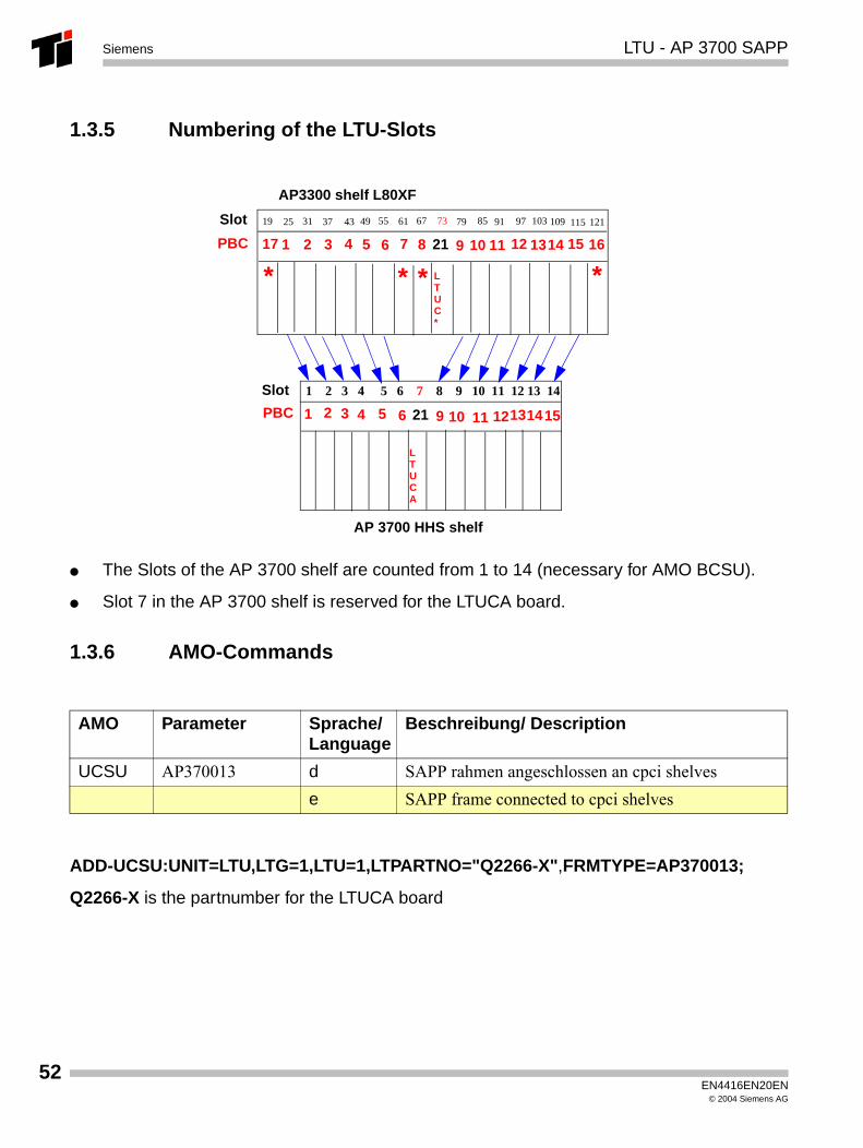
1.3.5 Numbering of the LTU-Slots
● The Slots of the AP 3700 shelf are counted from 1 to 14 (necessary for AMO BCSU).
● Slot 7 in the AP 3700 shelf is reserved for the LTUCA board.
1.3.6 AMO-Commands
ADD-UCSU:UNIT=LTU,LTG=1,LTU=1,LTPARTNO="Q2266-X",FRMTYPE=AP370013;
Q2266-X is the partnumber for the LTUCA board
AMO Parameter Sprache/Language
Beschreibung/ Description
UCSU AP370013 d SAPP rahmen angeschlossen an cpci shelvese SAPP frame connected to cpci shelves
1 2 3 4 5 6 7 8 9 10 11 12 13 14
LTUCA
AP 3700 HHS shelf
LTUC*
19 3731 7325 615543 49 85 91 97 103 109 115 12167 79
AP3300 shelf L80XF
1
Slot
PBC
Slot
PBC 2 3
3 4
4
5
5
6
6
72
1 11
10
10
9
9
8 11 13
12
12 161514
13
2117
21
*** *
1415
EN4416EN20EN© 2004 Siemens AG
LTUCA Siemens
1.3.7 Control board LTUCA for AP 3700 (LTU)
The LTUCA (Line Trunk Unit Control Advanced) is the interface between central and peripheral parts of the system. The LTUCA selects the signals from the active control unit and distributes them to the appropriate boards in the LTU shelf (LTU shelf is a general expression for all types of peripheral shelf. It can be one of the compact or extended compact shelves). The LTUCA also receives signals from the peripheral boards and transmits them to the common control.
Existing LTU cables are replaced by the new high-speed HSC cables (RJ45 CAT5). The signals are routed in a multiplexed data flow. This multiplex functionality is supported on the "common control" side of the RTM board and on the peripheral side of the LTUCA board.
Two HSC interfaces are provided on the LTUCA for CCA and CCB. Two additional lines are con-nected for broadband applications(overlay shelf function). Four RJ45 connector sockets are in-stalled for this on the front of the LTUCA board. In this case, a maximum of only eight peripheral LTU shelves can be connected for each HiPath 4000 V2 system.
The board can be integrated in the following system architectures:
● Hicom 300 (Atlantic architecture)
● HiPath 4000 (AP 3300 flexpack)
● HiPath 4000 (AP 3700 19“ architecture)
The LTUCA is mainly used in the AP 3300 or AP 3700 basic box in a "DSCXL in CompactPCI shelf" instead of the NCUI board.
The LTUCA does not replace the LTUCX or LTUCE in existing systems. These boards are still used because the LTUCA is not compatible with existing processor boards.
EN4416EN20EN© 2004 Siemens AG
53
54
LTUCASiemens
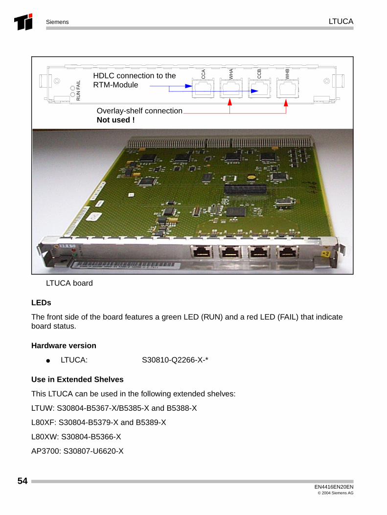
LTUCA board
LEDs
The front side of the board features a green LED (RUN) and a red LED (FAIL) that indicate board status.
Hardware version
● LTUCA: S30810-Q2266-X-*
Use in Extended Shelves
This LTUCA can be used in the following extended shelves:
LTUW: S30804-B5367-X/B5385-X and B5388-X
L80XF: S30804-B5379-X and B5389-X
L80XW: S30804-B5366-X
AP3700: S30807-U6620-X
WH
A
CC
B
WH
B
CC
A
RU
N F
AIL
Overlay-shelf connectionNot used !
HDLC connection to theRTM-Module
EN4416EN20EN© 2004 Siemens AG
LTUCA Siemens
Cable types
The following CAT 5 RJ45 cable types are available for connecting the LTU shelf:
C39195-Z7211-A7, 7-m twisted cable, 10BT (RJ45)
C39195-Z7211-A50, 5-m twisted cable, 10BT (RJ45)
C39195-Z7211-A100, 10-m twisted cable, 10BT (RJ45)
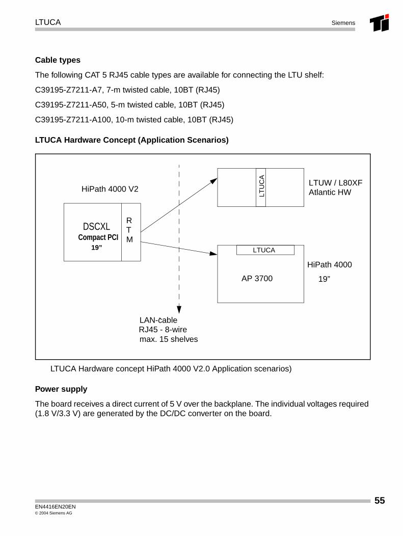
LTUCA Hardware Concept (Application Scenarios)
LTUCA Hardware concept HiPath 4000 V2.0 Application scenarios)
Power supply
The board receives a direct current of 5 V over the backplane. The individual voltages required (1.8 V/3.3 V) are generated by the DC/DC converter on the board.
RTM
DSCXL
HiPath 4000 V2
LTU
CA
LTUCA
Compact PCI
LAN-cableRJ45 - 8-wire
HiPath 4000
-
AP 3700
max. 15 shelves
19”
19”
LTUW / L80XFAtlantic HW
EN4416EN20EN© 2004 Siemens AG
55
56
LTUCASiemens
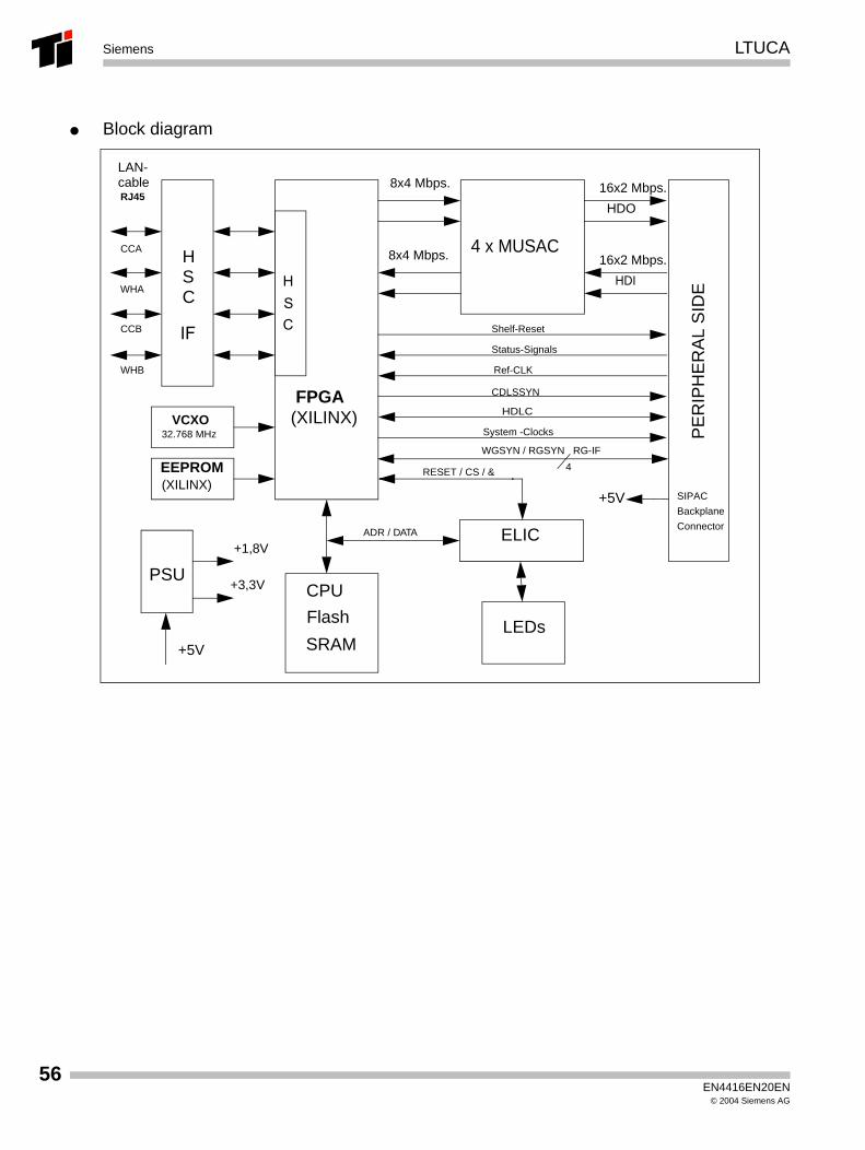
● Block diagram
4 x MUSAC
FPGA
LEDs
ELIC
PSU
HSC
CPU
Flash
SRAM+5V
+3,3V
+1,8V
EEPROM
Shelf-Reset
Status-Signals
Ref-CLK
CDLSSYN
HDLC
PE
RIP
HE
RA
L S
IDE
LAN-cable
32.768 MHzVCXO
(XILINX)
8x4 Mbps. 16x2 Mbps.
8x4 Mbps. 16x2 Mbps.
HDO
HDI
SIPAC
Backplane
Connector
CCA
WHA
CCB
WHB
(XILINX)System -Clocks
HSCIF
RJ45
4
WGSYN / RGSYN RG-IF
+5V
ADR / DATA
RESET / CS / &
EN4416EN20EN© 2004 Siemens AG
LTUCA Siemens
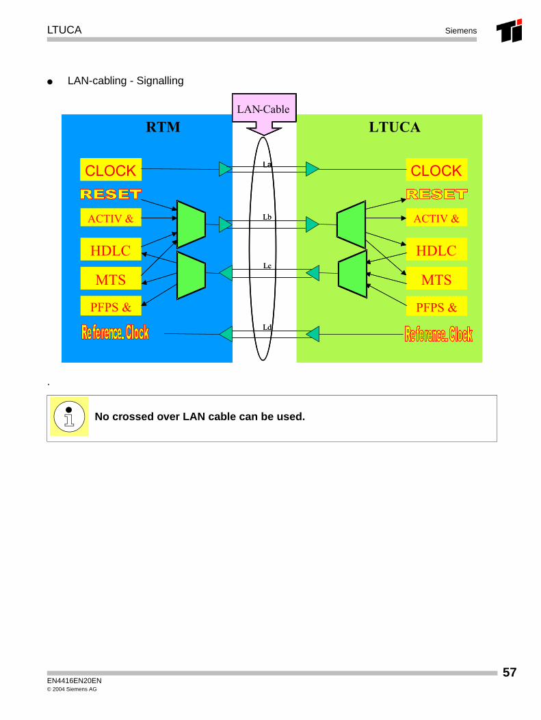
● LAN-cabling - Signalling
.
No crossed over LAN cable can be used.
CLOCK CLOCKLa
ACTIV &
HDLC
MTS
ACTIV &
HDLC
MTS
Lb
Lc
PFPS &PFPS &Ld
RTM LTUCALAN-KabelLAN-Cable
CLOCK CLOCKLa
ACTIV &
HDLC
MTS
ACTIV &
HDLC
MTS
Lb
Lc
PFPS &PFPS &Ld
RTM LTUCALAN-KabelLAN-CableLAN-KabelLAN-Cable
EN4416EN20EN© 2004 Siemens AG
57
58
LTUCASiemens
EN4416EN20EN© 2004 Siemens AG
AP 3700-IP SAPP Siemens
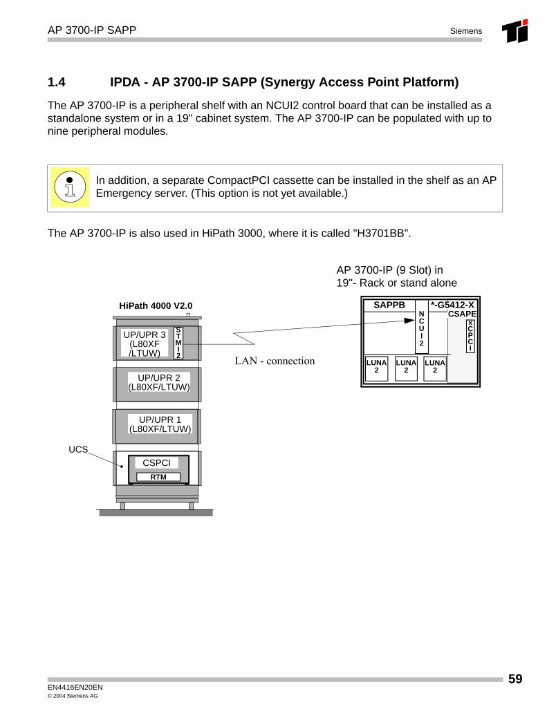
1.4 IPDA - AP 3700-IP SAPP (Synergy Access Point Platform)
The AP 3700-IP is a peripheral shelf with an NCUI2 control board that can be installed as a standalone system or in a 19" cabinet system. The AP 3700-IP can be populated with up to nine peripheral modules.
The AP 3700-IP is also used in HiPath 3000, where it is called "H3701BB".
In addition, a separate CompactPCI cassette can be installed in the shelf as an AP Emergency server. (This option is not yet available.)
AP 3700-IP (9 Slot) in19"- Rack or stand alone
LUNA2
LUNA2
LUNA2
SAPPB *-G5412-XCSAPE
xCPCI
NCUI2
HiPath 4000 V2.0
UP/UPR 1(L80XF/LTUW)
UP/UPR 2(L80XF/LTUW)
UCS
UP/UPR 3(L80XF/LTUW)
STMI2
RTM
CSPCI
LAN - connection
EN4416EN20EN© 2004 Siemens AG
59
60
AP 3700-IP SAPPSiemens
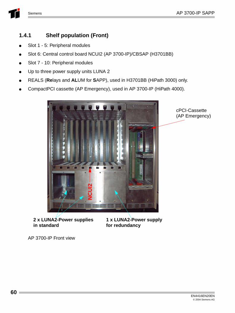
1.4.1 Shelf population (Front)
● Slot 1 - 5: Peripheral modules
● Slot 6: Central control board NCUI2 (AP 3700-IP)/CBSAP (H3701BB)
● Slot 7 - 10: Peripheral modules
● Up to three power supply units LUNA 2
● REALS (Relays and ALUM for SAPP), used in H3701BB (HiPath 3000) only.
● CompactPCI cassette (AP Emergency), used in AP 3700-IP (HiPath 4000).
AP 3700-IP Front view
NC
UI2
cPCI-Cassette(AP Emergency)
2 x LUNA2-Power suppliesin standard
1 x LUNA2-Power supplyfor redundancy
EN4416EN20EN© 2004 Siemens AG
AP 3700-IP SAPP Siemens
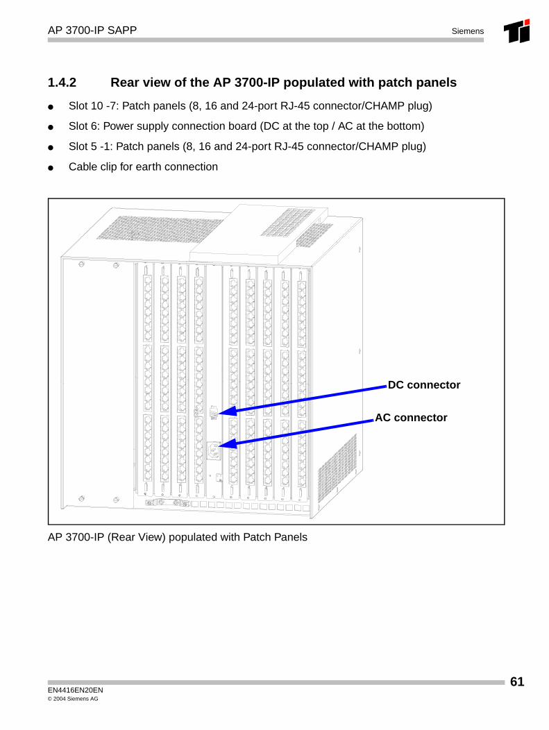
1.4.2 Rear view of the AP 3700-IP populated with patch panels
● Slot 10 -7: Patch panels (8, 16 and 24-port RJ-45 connector/CHAMP plug)
● Slot 6: Power supply connection board (DC at the top / AC at the bottom)
● Slot 5 -1: Patch panels (8, 16 and 24-port RJ-45 connector/CHAMP plug)
● Cable clip for earth connection
AP 3700-IP (Rear View) populated with Patch Panels
DC connector
AC connector
EN4416EN20EN© 2004 Siemens AG
61
62
AP 3700-IP SAPPSiemens
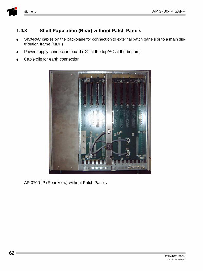
1.4.3 Shelf Population (Rear) without Patch Panels
● SIVAPAC cables on the backplane for connection to external patch panels or to a main dis-tribution frame (MDF)
● Power supply connection board (DC at the top/AC at the bottom)
● Cable clip for earth connection
AP 3700-IP (Rear View) without Patch Panels
EN4416EN20EN© 2004 Siemens AG
AP 3700-IP SAPP Siemens
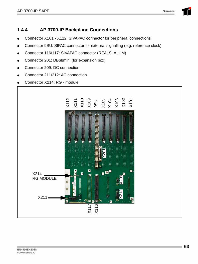
1.4.4 AP 3700-IP Backplane Connections
● Connector X101 - X112: SIVAPAC connector for peripheral connections
● Connector 9SU: SIPAC connector for external signalling (e.g. reference clock)
● Connector 116/117: SIVAPAC connector (REALS, ALUM)
● Connector 201: DB68mini (for expansion box)
● Connector 209: DC connection
● Connector 211/212: AC connection
● Connector X214: RG - module
X10
1
X10
2
X10
3
X10
4
X10
5
9SU
X10
9
X11
0
X11
1
X11
2
X20
1
X21
2X
209
X11
6
X11
7
X214RG MODULE
X211
EN4416EN20EN© 2004 Siemens AG
63
64
AP 3700-IP SAPPSiemens
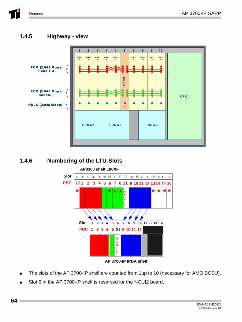
1.4.5 Highway - view
1.4.6 Numbering of the LTU-Slots
● The slots of the AP 3700-IP shelf are counted from 1up to 10 (necessary for AMO BCSU).
● Slot 6 in the AP 3700-IP shelf is reserved for the NCUI2 board.
L UN A2 L UN A2
NC
UI2
CP C I
L UN A2
PB C1
PB C2
PB C3
PB C4
PB C5
PB C9
PB C10
PB C11
PB C12
P CM (2.04 8 M b p s)Bu n d le A
P CM (2.04 8 M b p s)Bu n d le F
1 2 3 4 5 6 7 8 9 10
HDL C ( 2.048 M b p s)
L UN A2 L UN A2
NC
UI2
CP C I
L UN A2
PB C1
PB C2
PB C3
PB C4
PB C5
PB C9
PB C10
PB C11
PB C12
PB C1
PB C2
PB C3
PB C4
PB C5
PB C9
PB C10
PB C11
PB C12
P CM (2.04 8 M b p s)Bu n d le A
P CM (2.04 8 M b p s)Bu n d le A
P CM (2.04 8 M b p s)Bu n d le F
1 2 3 4 5 6 7 8 9 101 2 3 4 5 6 7 8 9 10
HDL C ( 2.048 M b p s)HDL C ( 2.048 M b p s)
1 2 3 4 5 6 7 8 9 10 11 12 13 14
NCUI2
AP 3700-IP IPDA shelf
NCUI2
19 3731 7325 615543 49 85 91 97 103 109 115 12167 79
AP3300 shelf L80XF
1
Slot
PBC
Slot
PBC 2 3
3 4
4
5
5
6 72
1
109
9
8 11 1312 1615142117
21
*** ** * **
10 11 12
EN4416EN20EN© 2004 Siemens AG
AP 3700-IP SAPP Siemens
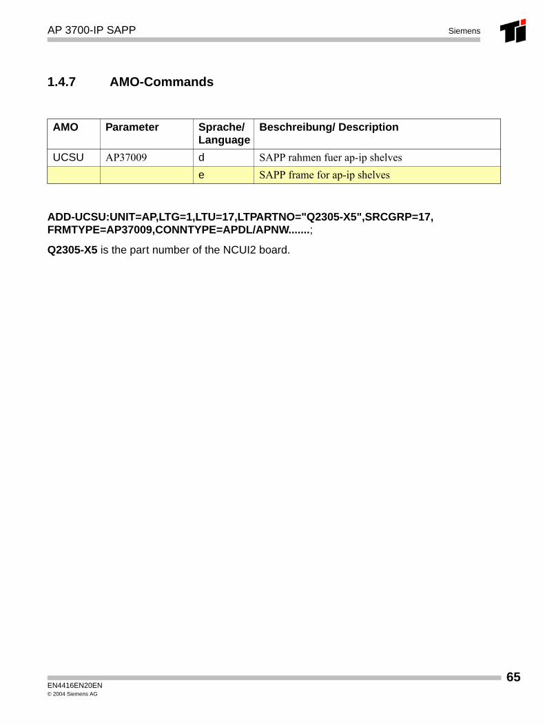
1.4.7 AMO-Commands
ADD-UCSU:UNIT=AP,LTG=1,LTU=17,LTPARTNO="Q2305-X5",SRCGRP=17, FRMTYPE=AP37009,CONNTYPE=APDL/APNW.......;
Q2305-X5 is the part number of the NCUI2 board.
AMO Parameter Sprache/Language
Beschreibung/ Description
UCSU AP37009 d SAPP rahmen fuer ap-ip shelvese SAPP frame for ap-ip shelves
EN4416EN20EN© 2004 Siemens AG
65

66
AP 3700-IP SAPPSiemens
EN4416EN20EN© 2004 Siemens AG
NCUI2 Siemens
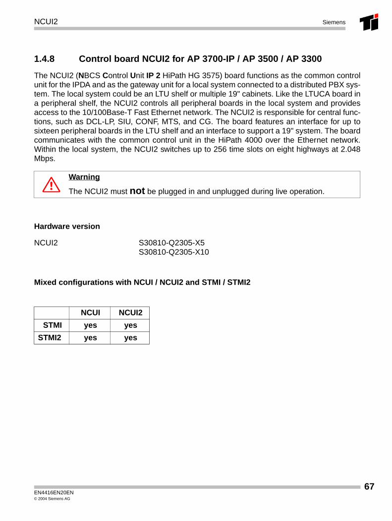
1.4.8 Control board NCUI2 for AP 3700-IP / AP 3500 / AP 3300
The NCUI2 (NBCS Control Unit IP 2 HiPath HG 3575) board functions as the common controlunit for the IPDA and as the gateway unit for a local system connected to a distributed PBX sys-tem. The local system could be an LTU shelf or multiple 19" cabinets. Like the LTUCA board ina peripheral shelf, the NCUI2 controls all peripheral boards in the local system and providesaccess to the 10/100Base-T Fast Ethernet network. The NCUI2 is responsible for central func-tions, such as DCL-LP, SIU, CONF, MTS, and CG. The board features an interface for up tosixteen peripheral boards in the LTU shelf and an interface to support a 19" system. The boardcommunicates with the common control unit in the HiPath 4000 over the Ethernet network.Within the local system, the NCUI2 switches up to 256 time slots on eight highways at 2.048Mbps.
Hardware version
Mixed configurations with NCUI / NCUI2 and STMI / STMI2
7 Warning
The NCUI2 must not be plugged in and unplugged during live operation.
NCUI2 S30810-Q2305-X5S30810-Q2305-X10
NCUI NCUI2
STMI yes yes
STMI2 yes yes
EN4416EN20EN© 2004 Siemens AG
67
68
NCUI2Siemens
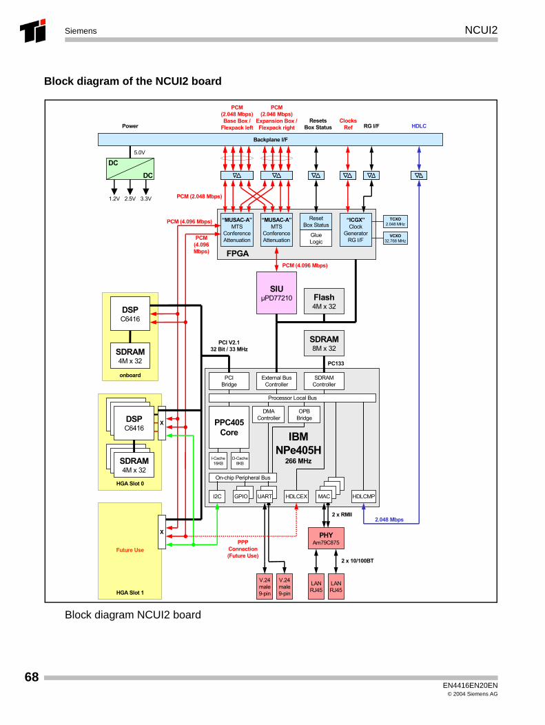
Block diagram of the NCUI2 board
Block diagram NCUI2 board
SDRAM8M x 32
Backplane I/F
5.0V
PC133
External BusController
PPC405Core
On-chip Peripheral Bus
I2C
Processor Local Bus
HDLCEX
SDRAMController
PCIBridge
Flash4M x 32
DC
DC
1.2V 2.5V 3.3V
SDRAM4M x 32
DSPC6416
PHYAm79C875
2 x RMII
V.24male9-pin
HGA Slot 0
SDRAM4M x 32
DSPC6416
FPGA
GlueLogic
ResetBox Status
X
2 x 10/100BT
LANRJ45
HDLC
PCM(2.048 Mbps)Base Box /
Flexpack left
2.048 Mbps
PowerResets
Box Status
Future Use
HGA Slot 1
X
onboard
GPIO
DMAController
MAC
OPBBridge
PCM (4.096 Mbps)
I-Cache16KB
D-Cache8KB
PCM(2.048 Mbps)
Expansion Box /Flexpack right
V.24male9-pin
IBMNPe405H
266 MHz
UART
“MUSAC-A”MTS
ConferenceAttenuation
“MUSAC-A”MTS
ConferenceAttenuation
“ICGX”Clock
GeneratorRG I/F
SIUµPD77210
RG I/F
PCM (2.048 Mbps)
PCM (4.096 Mbps)
PCM(4.096 Mbps)
ClocksRef
LANRJ45
TCXO2.048 MHz
VCXO32.768 MHz
PCI V2.132 Bit / 33 MHz
PPPConnection (Future Use)
HDLCMP
EN4416EN20EN© 2004 Siemens AG
NCUI2 Siemens
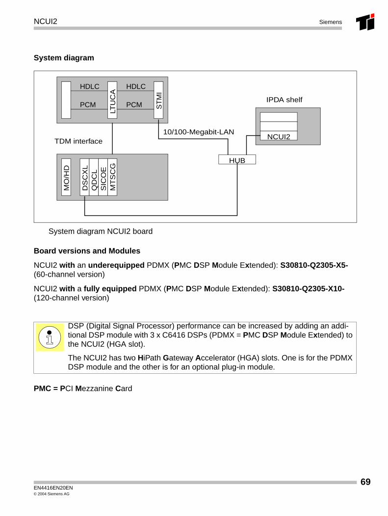
System diagram
System diagram NCUI2 board
Board versions and Modules
NCUI2 with an underequipped PDMX (PMC DSP Module Extended): S30810-Q2305-X5-(60-channel version)
NCUI2 with a fully equipped PDMX (PMC DSP Module Extended): S30810-Q2305-X10-(120-channel version)
PMC = PCI Mezzanine Card
DSP (Digital Signal Processor) performance can be increased by adding an addi-tional DSP module with 3 x C6416 DSPs (PDMX = PMC DSP Module Extended) to the NCUI2 (HGA slot).
The NCUI2 has two HiPath Gateway Accelerator (HGA) slots. One is for the PDMX DSP module and the other is for an optional plug-in module.
HDLC
PCM ST
MI
LTU
CA
HDLC
PCM
DS
CX
LQ
DC
LS
ICO
EM
TS
CG
MO
/HD
NCUI2
HUB
10/100-Megabit-LANTDM interface
IPDA shelf
EN4416EN20EN© 2004 Siemens AG
69
70
NCUI2Siemens
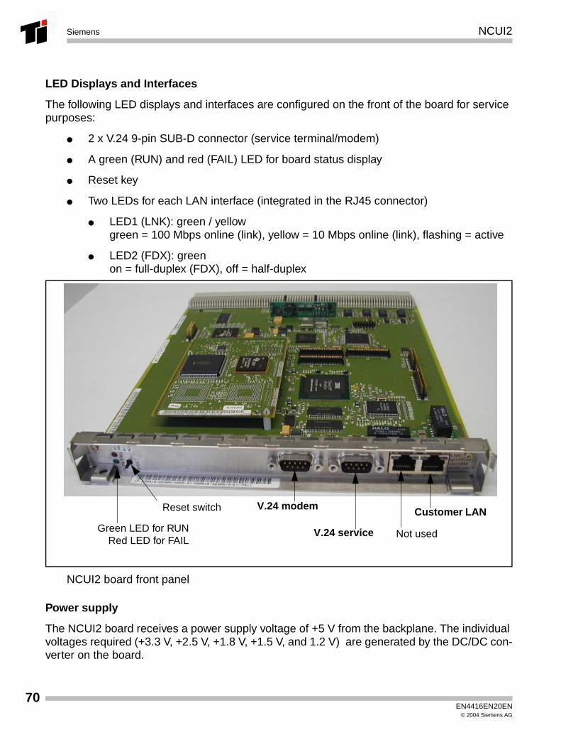
LED Displays and Interfaces
The following LED displays and interfaces are configured on the front of the board for service purposes:
● 2 x V.24 9-pin SUB-D connector (service terminal/modem)
● A green (RUN) and red (FAIL) LED for board status display
● Reset key
● Two LEDs for each LAN interface (integrated in the RJ45 connector)
● LED1 (LNK): green / yellowgreen = 100 Mbps online (link), yellow = 10 Mbps online (link), flashing = active
● LED2 (FDX): greenon = full-duplex (FDX), off = half-duplex
NCUI2 board front panel
Power supply
The NCUI2 board receives a power supply voltage of +5 V from the backplane. The individual voltages required (+3.3 V, +2.5 V, +1.8 V, +1.5 V, and 1.2 V) are generated by the DC/DC con-verter on the board.
Reset switch
Green LED for RUNRed LED for FAIL
V.24 modem
V.24 service Not used
Customer LAN
EN4416EN20EN© 2004 Siemens AG
LUNA 2 Power supply Siemens
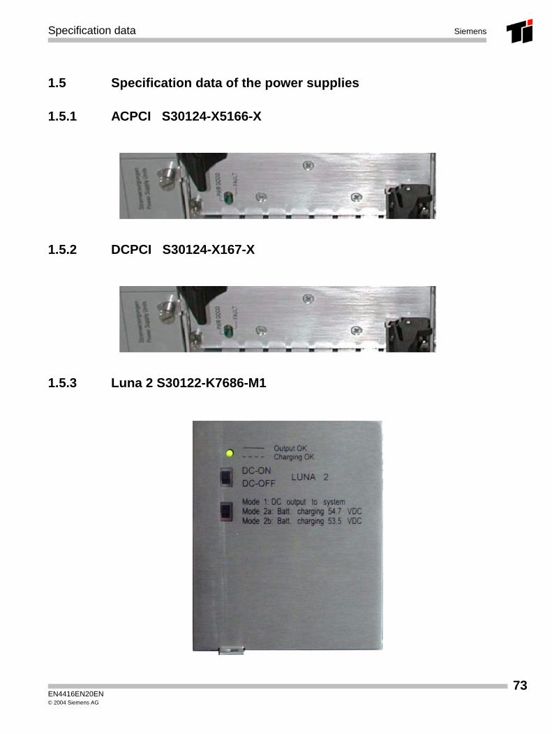
1.4.9 LUNA 2 Power supply
The AC-to-DC shelf power supply unit (LUNA 2) converts AC power to DC on the HiPath IP Distributed Architecture (IPDA) system. The nominal AC input voltage is 90-264 VAC from the utility outlet that provides power to the cabinet. The DC output voltages are: -5.0 V, +5.1 V, +12 V, -12 V and –48 V. The frequency is between 47 Hertz (Hz) and 63 Hz.
LED Indications and Switches
The front panel features one green LED and two slide switches:
● Green LED:This indicates whether the individual voltages are within tolerance. If the voltage is outsidetolerance, the LED goes out. Depending on the operating mode, the LED may illuminate orflash.
● Switch 1: On/off power supply switch
● Switch 2: Operating mode switchThe power supply unit can be used for supplying power or charging the battery. Set the op-erating switch to the correct position, one of three(see front panel labelling).
Operating modes:
– Mode 1: as a power supply unit (LED illuminated)
– Mode 2a: as a battery charger (flashing LED) for maintenance-free dry-cell batteries(charging voltage: 54.7 VDC)
– Mode 2b: as a battery charger (flashing LED) for wet-cell batteries requiring low charg-ing voltage (53.5 VDC)
The power supply is used in the AP 3700 and also in the AP 3700-IP !
EN4416EN20EN© 2004 Siemens AG
71
72
LUNA 2 Power supplySiemens
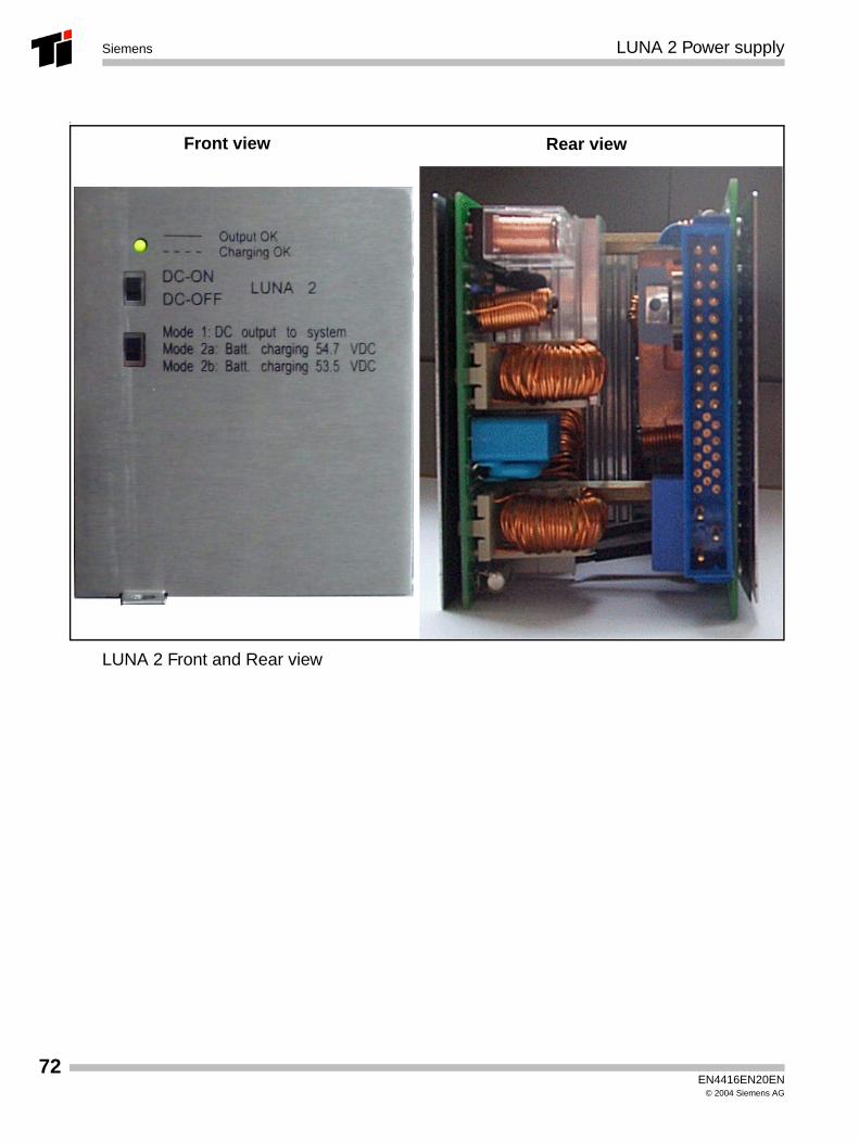
T
LUNA 2 Front and Rear view
Front view Rear view
EN4416EN20EN© 2004 Siemens AG
Specification data Siemens
1.5 Specification data of the power supplies
1.5.1 ACPCI S30124-X5166-X
1.5.2 DCPCI S30124-X167-X
1.5.3 Luna 2 S30122-K7686-M1
EN4416EN20EN© 2004 Siemens AG
73
74
Specification dataSiemens
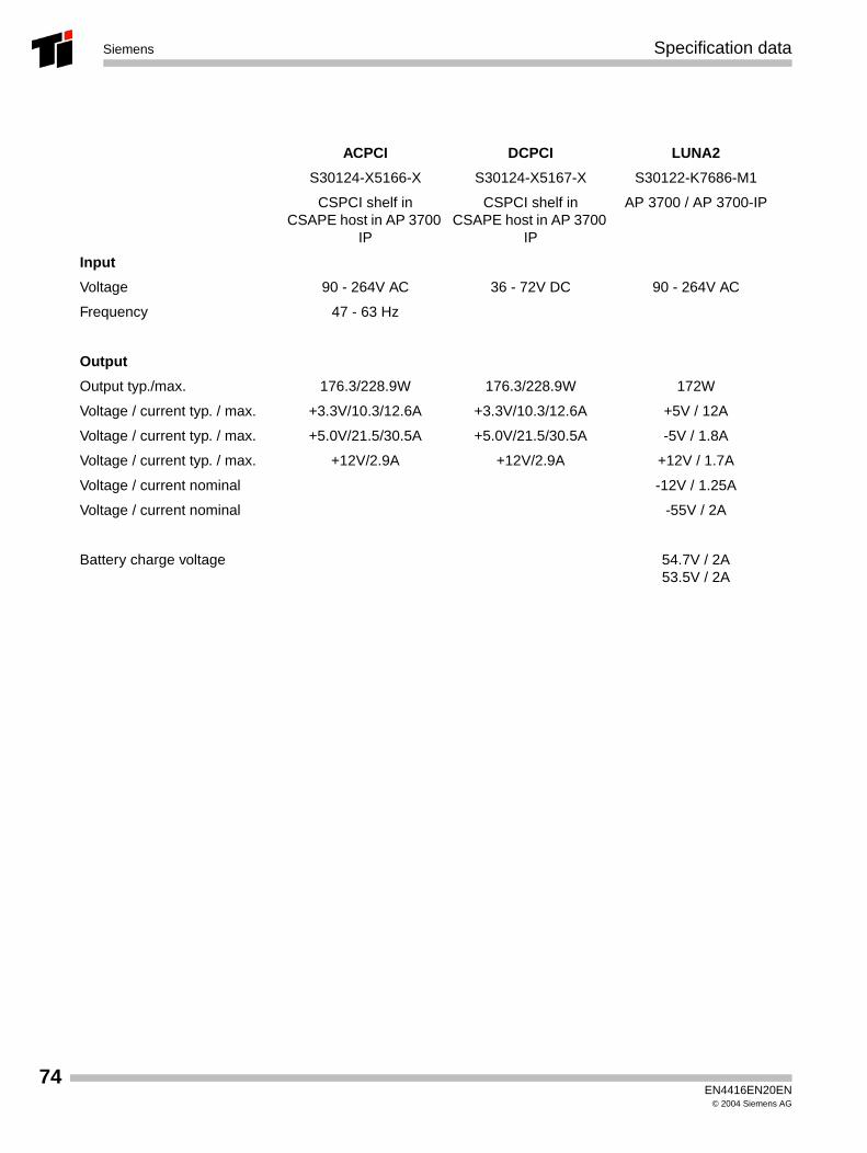
ACPCI DCPCI LUNA2
S30124-X5166-X S30124-X5167-X S30122-K7686-M1
CSPCI shelf inCSAPE host in AP 3700
IP
CSPCI shelf inCSAPE host in AP 3700
IP
AP 3700 / AP 3700-IP
Input
Voltage 90 - 264V AC 36 - 72V DC 90 - 264V AC
Frequency 47 - 63 Hz
Output
Output typ./max. 176.3/228.9W 176.3/228.9W 172W
Voltage / current typ. / max. +3.3V/10.3/12.6A +3.3V/10.3/12.6A +5V / 12A
Voltage / current typ. / max. +5.0V/21.5/30.5A +5.0V/21.5/30.5A -5V / 1.8A
Voltage / current typ. / max. +12V/2.9A +12V/2.9A +12V / 1.7A
Voltage / current nominal -12V / 1.25A
Voltage / current nominal -55V / 2A
Battery charge voltage 54.7V / 2A53.5V / 2A
EN4416EN20EN© 2004 Siemens AG
STMI2 board Siemens
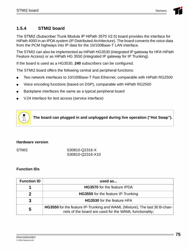
1.5.4 STMI2 board
The STMI2 (Subscriber Trunk Module IP HiPath 3570 V2.0) board provides the interface for HiPath 4000 in an IPDA system (IP Distributed Architecture). The board converts the voice data from the PCM highways into IP data for the 10/100Base-T LAN interface.
The STMI2 can also be implemented as HiPath HG3530 (integrated IP gateway for HFA HiPathFeature Access) or as HiPath HG 3550 (integrated IP gateway for IP Trunking).
If the board is used as a HG3530, 240 subscribers can be configured.
The STMI2 board offers the following central and peripheral functions:
● Two network interfaces to 10/100Base-T Fast Ethernet, comparable with HiPath RG2500
● Voice encoding functions (based on DSP), comparable with HiPath RG2500
● Backplane interfaces the same as a typical peripheral board
● V.24 interface for test access (service interface)
Hardware version
Function IDs
The board can plugged in and unplugged during live operation (“Hot Swap”).
STMI2 S30810-Q2316-X S30810-Q2316-X10
Function ID used as...
1 HG3570 for the feature IPDA
2 HG3550 for the feature IP-Trunking
3 HG3530 for the feature HFA
5 HG3550 for the feature IP-Trunking and WAML (Mixture); The last 30 B-chan-nels of the board are used for the WAML functionality;
EN4416EN20EN© 2004 Siemens AG
75
76
STMI2 boardSiemens
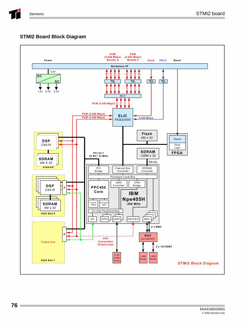
STMI2 Board Block DiagramI
STMI2 Block Diagram
SDRAM128M x 32
Backplane I/F
5.0V
PC133
IBMNpe405H
266 MHz
External BusController
PPC405Core
On-chip Peripheral Bus
I2C
Processor Local Bus
HDLCEX
SDRAMController
PCIBridge
Flash4M x 32
ELICPEB20550
DC
DC
1.2V 2.5V 3.3V
SDRAM4M x 32
DSPC6416
PCI V2.132 Bit / 33 MHz
PHYAm79C875
2 x RMII
V.24male9-pin
HGA Slot 0
SDRAM4M x 32
DSPC6416
GlueLogic
Reset
X
PCM (4.096 Mbps)
2 x 10/100BT
LANRJ45
LANRJ45
2.048 Mbps
MUX
PCM (2.048 Mbps)
Future Use
HGA Slot 1
X
onboard
GPIO
DMAController
MACUART
OPBBridge
PCM (4.096 Mbps)
I-Cache16KB
D-Cache8KB
PPPConnection (Future Use)
HDLC
PCM(2.048 Mbps)
Bundle APower Reset
PCM(2.048 Mbps)
Bundle F Clock
FPGA
DSPC6416
SDRAM4M X 32
EN4416EN20EN© 2004 Siemens AG
STMI2 board Siemens
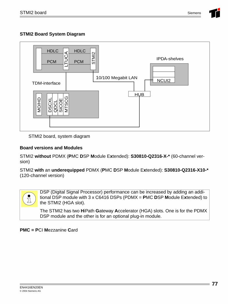
STMI2 Board System Diagram
STMI2 board, system diagram
Board versions and Modules
STMI2 without PDMX (PMC DSP Module Extended): S30810-Q2316-X-* (60-channel ver-sion)
STMI2 with an underequipped PDMX (PMC DSP Module Extended): S30810-Q2316-X10-* (120-channel version)
PMC = PCI Mezzanine Card
DSP (Digital Signal Processor) performance can be increased by adding an addi-tional DSP module with 3 x C6416 DSPs (PDMX = PMC DSP Module Extended) to the STMI2 (HGA slot).
The STMI2 has two HiPath Gateway Accelerator (HGA) slots. One is for the PDMX DSP module and the other is for an optional plug-in module.
HDLC
PCM ST
MI2
LTU
CAHDLC
PCM
DS
CX
LQ
DC
LS
ICO
EM
TS
CG
MO
/HD
NCUI2
HUB
10/100 Megabit LANTDM-interface
IPDA-shelves
EN4416EN20EN© 2004 Siemens AG
77
78
STMI2 boardSiemens
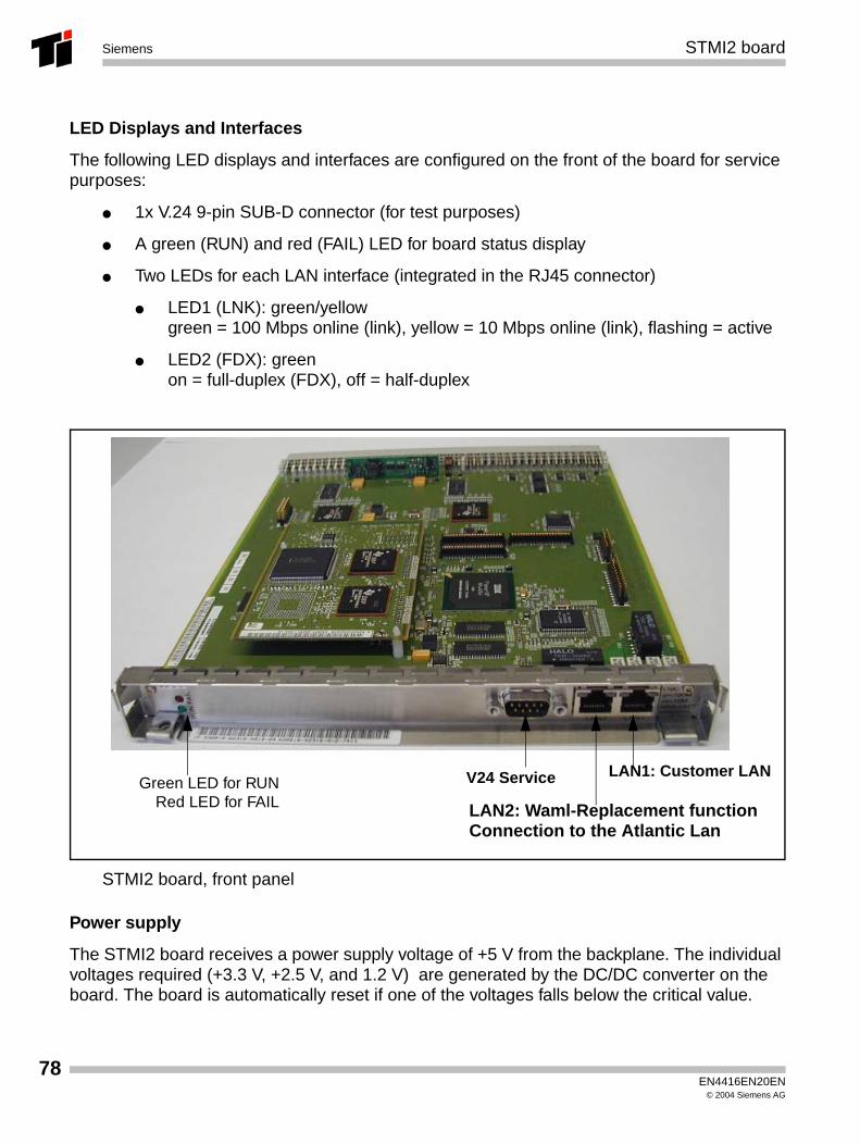
LED Displays and Interfaces
The following LED displays and interfaces are configured on the front of the board for service purposes:
● 1x V.24 9-pin SUB-D connector (for test purposes)
● A green (RUN) and red (FAIL) LED for board status display
● Two LEDs for each LAN interface (integrated in the RJ45 connector)
● LED1 (LNK): green/yellowgreen = 100 Mbps online (link), yellow = 10 Mbps online (link), flashing = active
● LED2 (FDX): greenon = full-duplex (FDX), off = half-duplex
STMI2 board, front panel
Power supply
The STMI2 board receives a power supply voltage of +5 V from the backplane. The individual voltages required (+3.3 V, +2.5 V, and 1.2 V) are generated by the DC/DC converter on the board. The board is automatically reset if one of the voltages falls below the critical value.
Green LED for RUNRed LED for FAIL
V24 Service LAN1: Customer LAN
LAN2: Waml-Replacement functionConnection to the Atlantic Lan
EN4416EN20EN© 2004 Siemens AG
Siemens
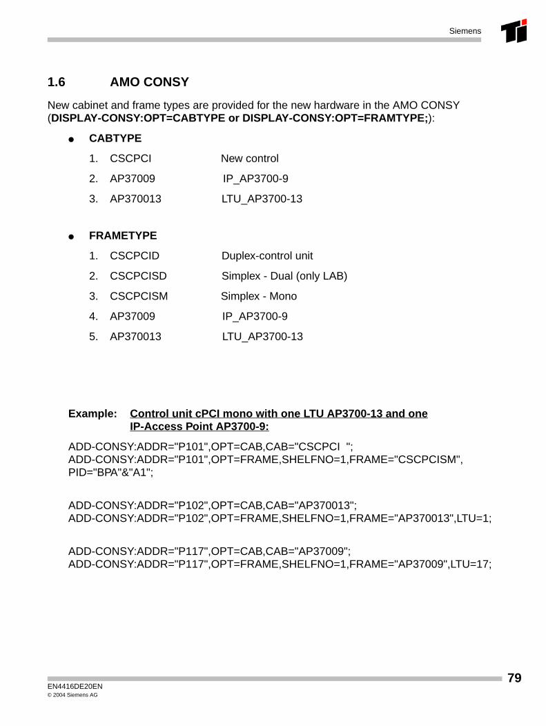
1.6 AMO CONSY
New cabinet and frame types are provided for the new hardware in the AMO CONSY(DISPLAY-CONSY:OPT=CABTYPE or DISPLAY-CONSY:OPT=FRAMTYPE;):
● CABTYPE
1. CSCPCI New control
2. AP37009 IP_AP3700-9
3. AP370013 LTU_AP3700-13
● FRAMETYPE
1. CSCPCID Duplex-control unit
2. CSCPCISD Simplex - Dual (only LAB)
3. CSCPCISM Simplex - Mono
4. AP37009 IP_AP3700-9
5. AP370013 LTU_AP3700-13
Example: Control unit cPCI mono with one LTU AP3700-13 and one IP-Access Point AP3700-9:
ADD-CONSY:ADDR="P101",OPT=CAB,CAB="CSCPCI ";ADD-CONSY:ADDR="P101",OPT=FRAME,SHELFNO=1,FRAME="CSCPCISM",PID="BPA"&"A1";
ADD-CONSY:ADDR="P102",OPT=CAB,CAB="AP370013";ADD-CONSY:ADDR="P102",OPT=FRAME,SHELFNO=1,FRAME="AP370013",LTU=1;
ADD-CONSY:ADDR="P117",OPT=CAB,CAB="AP37009";ADD-CONSY:ADDR="P117",OPT=FRAME,SHELFNO=1,FRAME="AP37009",LTU=17;
EN4416DE20EN© 2004 Siemens AG
79
80
Siemens
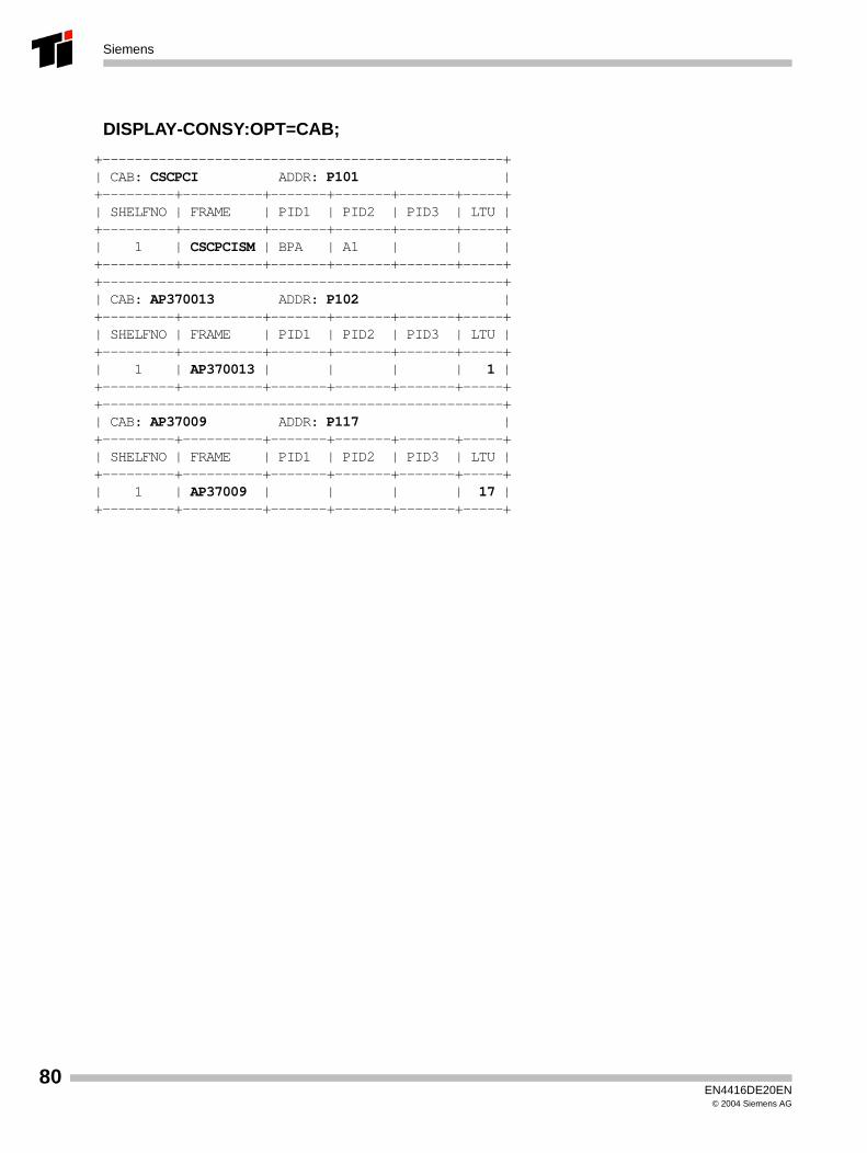
DISPLAY-CONSY:OPT=CAB;
+--------------------------------------------------+ | CAB: CSCPCI ADDR: P101 | +---------+----------+-------+-------+-------+-----+ | SHELFNO | FRAME | PID1 | PID2 | PID3 | LTU | +---------+----------+-------+-------+-------+-----+ | 1 | CSCPCISM | BPA | A1 | | | +---------+----------+-------+-------+-------+-----+ +--------------------------------------------------+ | CAB: AP370013 ADDR: P102 | +---------+----------+-------+-------+-------+-----+ | SHELFNO | FRAME | PID1 | PID2 | PID3 | LTU | +---------+----------+-------+-------+-------+-----+ | 1 | AP370013 | | | | 1 | +---------+----------+-------+-------+-------+-----+ +--------------------------------------------------+ | CAB: AP37009 ADDR: P117 | +---------+----------+-------+-------+-------+-----+ | SHELFNO | FRAME | PID1 | PID2 | PID3 | LTU | +---------+----------+-------+-------+-------+-----+ | 1 | AP37009 | | | | 17 | +---------+----------+-------+-------+-------+-----+
EN4416DE20EN© 2004 Siemens AG
Sevice: Hardware Siemens
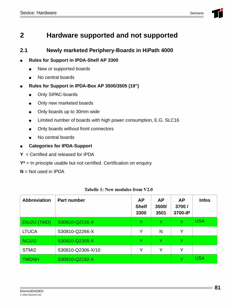
2 Hardware supported and not supported
2.1 Newly marketed Periphery-Boards in HiPath 4000
● Rules for Support in IPDA-Shelf AP 3300
● New or supported boards
● No central boards
● Rules for Support in IPDA-Box AP 3500/3505 (19")
● Only SIPAC-boards
● Only new marketed boards
● Only boards up to 30mm wide
● Limited number of boards with high power consumption, E.G. SLC16
● Only boards without front connectors
● No central boards
● Categories for IPDA-Support
Y = Certified and released for IPDA
Y* = In principle usable but not certified. Certification on enquiry.
N = Not used in IPDA
Tabelle 1: New modules from V2.0
Abbreviation Part number AP Shelf3300
AP 3500/3501
AP3700 /
3700-IP
Infos
DIU2U (TMD) S30810-Q2216-X Y Y Y USA
LTUCA S30810-Q2266-X Y N Y
NCUI2 S30810-Q2305-X Y Y Y
STMI2 S30810-Q2306-X/10 Y Y Y
TMDNH S30810-Q2192-X Y USA
EN4416EN20EN© 2004 Siemens AG
81
82
Sevice: HardwareSiemens
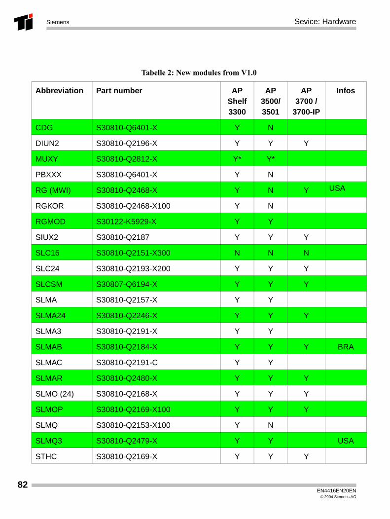
Tabelle 2: New modules from V1.0
Abbreviation Part number AP Shelf3300
AP 3500/3501
AP3700 /
3700-IP
Infos
CDG S30810-Q6401-X Y N
DIUN2 S30810-Q2196-X Y Y Y
MUXY S30810-Q2812-X Y* Y*
PBXXX S30810-Q6401-X Y N
RG (MWI) S30810-Q2468-X Y N Y USA
RGKOR S30810-Q2468-X100 Y N
RGMOD S30122-K5929-X Y Y
SIUX2 S30810-Q2187 Y Y Y
SLC16 S30810-Q2151-X300 N N N
SLC24 S30810-Q2193-X200 Y Y Y
SLCSM S30807-Q6194-X Y Y Y
SLMA S30810-Q2157-X Y Y
SLMA24 S30810-Q2246-X Y Y Y
SLMA3 S30810-Q2191-X Y Y
SLMAB S30810-Q2184-X Y Y Y BRA
SLMAC S30810-Q2191-C Y Y
SLMAR S30810-Q2480-X Y Y Y
SLMO (24) S30810-Q2168-X Y Y Y
SLMOP S30810-Q2169-X100 Y Y Y
SLMQ S30810-Q2153-X100 Y N
SLMQ3 S30810-Q2479-X Y Y USA
STHC S30810-Q2169-X Y Y Y
EN4416EN20EN© 2004 Siemens AG
Sevice: Hardware Siemens
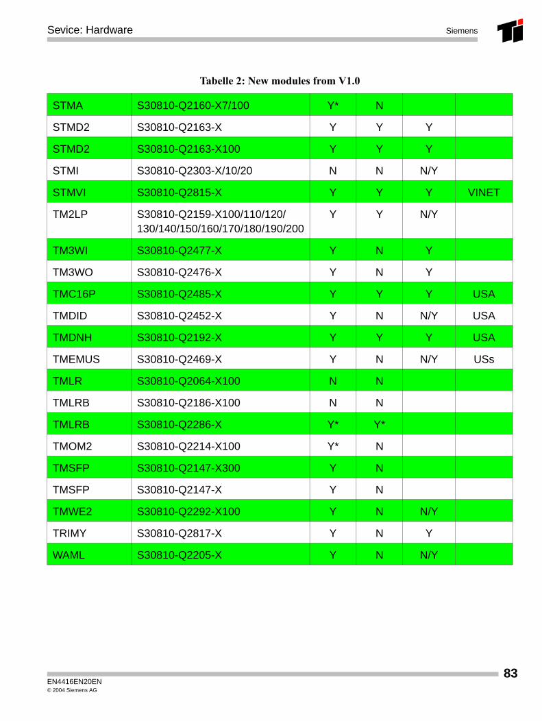
STMA S30810-Q2160-X7/100 Y* N
STMD2 S30810-Q2163-X Y Y Y
STMD2 S30810-Q2163-X100 Y Y Y
STMI S30810-Q2303-X/10/20 N N N/Y
STMVI S30810-Q2815-X Y Y Y VINET
TM2LP S30810-Q2159-X100/110/120/130/140/150/160/170/180/190/200
Y Y N/Y
TM3WI S30810-Q2477-X Y N Y
TM3WO S30810-Q2476-X Y N Y
TMC16P S30810-Q2485-X Y Y Y USA
TMDID S30810-Q2452-X Y N N/Y USA
TMDNH S30810-Q2192-X Y Y Y USA
TMEMUS S30810-Q2469-X Y N N/Y USs
TMLR S30810-Q2064-X100 N N
TMLRB S30810-Q2186-X100 N N
TMLRB S30810-Q2286-X Y* Y*
TMOM2 S30810-Q2214-X100 Y* N
TMSFP S30810-Q2147-X300 Y N
TMSFP S30810-Q2147-X Y N
TMWE2 S30810-Q2292-X100 Y N N/Y
TRIMY S30810-Q2817-X Y N Y
WAML S30810-Q2205-X Y N N/Y
Tabelle 2: New modules from V1.0
EN4416EN20EN© 2004 Siemens AG
83
84
Sevice: HardwareSiemens
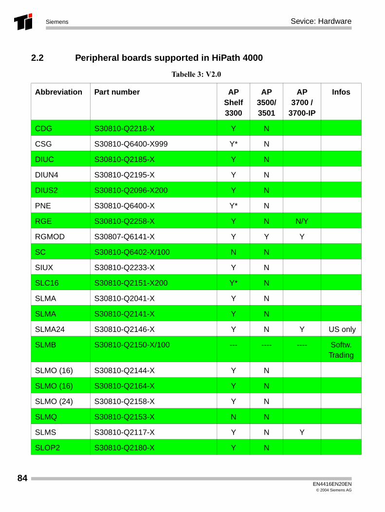
2.2 Peripheral boards supported in HiPath 4000
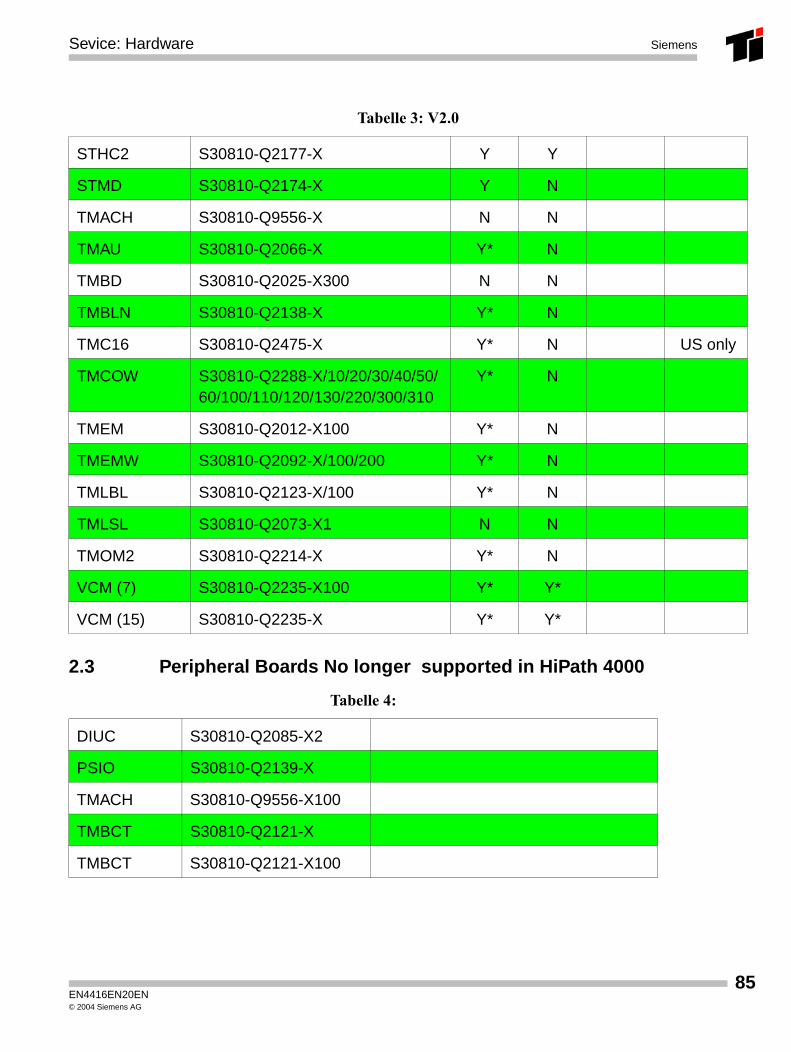
Tabelle 3: V2.0
Abbreviation Part number AP Shelf3300
AP3500/3501
AP3700 /
3700-IP
Infos
CDG S30810-Q2218-X Y N
CSG S30810-Q6400-X999 Y* N
DIUC S30810-Q2185-X Y N
DIUN4 S30810-Q2195-X Y N
DIUS2 S30810-Q2096-X200 Y N
PNE S30810-Q6400-X Y* N
RGE S30810-Q2258-X Y N N/Y
RGMOD S30807-Q6141-X Y Y Y
SC S30810-Q6402-X/100 N N
SIUX S30810-Q2233-X Y N
SLC16 S30810-Q2151-X200 Y* N
SLMA S30810-Q2041-X Y N
SLMA S30810-Q2141-X Y N
SLMA24 S30810-Q2146-X Y N Y US only
SLMB S30810-Q2150-X/100 --- ---- ---- Softw. Trading
SLMO (16) S30810-Q2144-X Y N
SLMO (16) S30810-Q2164-X Y N
SLMO (24) S30810-Q2158-X Y N
SLMQ S30810-Q2153-X N N
SLMS S30810-Q2117-X Y N Y
SLOP2 S30810-Q2180-X Y N
EN4416EN20EN© 2004 Siemens AG
Sevice: Hardware Siemens
2.3 Peripheral Boards No longer supported in HiPath 4000
STHC2 S30810-Q2177-X Y Y
STMD S30810-Q2174-X Y N
TMACH S30810-Q9556-X N N
TMAU S30810-Q2066-X Y* N
TMBD S30810-Q2025-X300 N N
TMBLN S30810-Q2138-X Y* N
TMC16 S30810-Q2475-X Y* N US only
TMCOW S30810-Q2288-X/10/20/30/40/50/60/100/110/120/130/220/300/310
Y* N
TMEM S30810-Q2012-X100 Y* N
TMEMW S30810-Q2092-X/100/200 Y* N
TMLBL S30810-Q2123-X/100 Y* N
TMLSL S30810-Q2073-X1 N N
TMOM2 S30810-Q2214-X Y* N
VCM (7) S30810-Q2235-X100 Y* Y*
VCM (15) S30810-Q2235-X Y* Y*
Tabelle 4:
DIUC S30810-Q2085-X2
PSIO S30810-Q2139-X
TMACH S30810-Q9556-X100
TMBCT S30810-Q2121-X
TMBCT S30810-Q2121-X100
Tabelle 3: V2.0
EN4416EN20EN© 2004 Siemens AG
85
86
Sevice: HardwareSiemens
EN4416EN20EN© 2004 Siemens AG