Embed Size (px)
Citation preview

1
Caratteristiche tecniche e istruzioni per l’installatore Technical features and direction for the technician
Variatori elettronici di velocità a diodi controllati per allacciamento a rete monofase. Regolazione a coppia costante per motori in corrente continua ad eccitazione separata.
Controlled diode electronic speed variators for monophase circuits. Constant pair regulation for separate excitement continuos current motors.
La serie MINIVAR N è disponibile in tre diverse versioni a seconda della esigenze meccaniche della macchina da azionare. La gamma di potenza disponibile è compresa tra 1 e 4,5 HP.
The MINIVAR N range is available in three different versions depending on the mechanical characteristics of the machine. The different power source types range from 1 to 4,5 HP.
MINIVAR N/U – Unidirezionale semicontrollato MINIVAR N/U – Semi-controlled single direction
Il gruppo di potenza di questa versione è costituito da un ponte raddrizzatore monofase semicontrollato a due semionde. Esso consente il comando monodirezionale del motore. E’ possibile invertire il senso di marcia tramite l’impiego di teleruttori ma soltanto a motore fermo. In nessun caso è tollerata la rotazione forzata del motore nel senso opposto a quello di marcia; non è infatti possibile il recupero dell’energia proveniente dalla macchina (sia essa inerziale o di reazione al moto). La frenatura può essere solo del tipo dinamico con resistenza di dissipazione.
The power unit for this version comprises a two semi-wave semi-controlled monophase bridge rectifier. This gives single-directional command of the motor. Direction can be reversed by remote control but only when motor is stopped. Fased rotation of motor in opposite direction to that of movement is impossible: energy produced by the machine cannot be recovered (whether this is inert energy or movement reaction). Braking must only be dynamic with diminishing resistance.
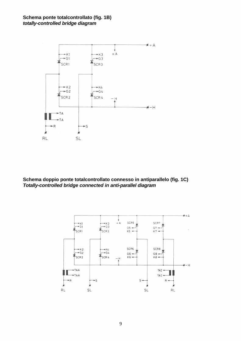
MINIVAR N/R – Rigenerativo totalcontrollato MINIVAR N/R – Totally controlled regenerative
Il gruppo di potenza di questa versione è costituito da un ponte raddrizzatore monofase a due semionde totalcontrollato. Esso permette il comando monodirezionale del motore, la rotazione forzata dall’esterno nel senso opposto a quello di marcia (per es. svolgitore) e l’inversione rapida di coppia e velocità mediante teleruttori con rigenerazione di energia durante la frenatura o l’inversione del senso di rotazione. Le frenature in questa versione avvengono a coppia costante.
The power unit for this version comprises a two semi-wave totally controlled monophase bridge rectifier. This gives single-directional command of the motor, external fased rotations in the opposite direction to that of movement (e.g. winder) and the rapid remote control inversion of pair and speed with energy regeneration during braking and inversion of rotation direction. On this version, braking is by means of constant pair.
MINIVAR N/RR – Reversibile bidirezionale MINIVAR N/RR – Reversible bi-directional Il gruppo di potenza di questa versione è costituita da due ponti raddrizzatori monofase totalcontrollati connessi in antiparallelo. Questa struttura permette il totale controllo del motore potendo agire su tutti i quattro quadranti del diagramma coppia/velocità. E’ perciò possibile in modo completamente statico (senza l’uso di teleruttori) invertire il senso di moto ed effettuare salti di velocità nei due sensi con la possibilità di controllare le coppie acceleranti e frenanti in ogni istante. Possono essere montati circuiti di rampe indipendenti che consentono la realizzazione di diagrammi di lavoro prestabiliti (traslazioni, posizionamenti, ecc.). Permane la caratteristica per cui nelle fasi di frenatura e/o inversione l’energia inerziale dell’intero sistema meccanico viene recuperata in rete senza alcuna dissipazione, consentendo un significativo risparmio energetico, tanto più interessante quanto più elevata è la costante di tempo della macchina.
The power unit for this version comprises two totally controlled monophase bridge rectifiers connected in anti-parallel. This arrangement gives total control of the motor by adjusting the four dials on the couple-speed diagram. Therefore, motor direction can be reversed in static mode (without using remote control) and alter speed in both directions with instantaneous control over the acceleration and braking pairs. Independent range circuits can be fitted so that various programmable work diagrams can be created (traversing, positioning, etc.). It also has a feature so that during braking and/or inversion, the inert energy produced by the entire mechanical system is recycled without any fall in power levels, giving substantial energy savings, even more interesting when machine time constants are very high.
TIPI E POTENZE VERSIONS AND POWER TYPES
I OUT (A) POT. MECC UNIDIREZIONALE RIGENERATIVO REVERSIBILE NOM. PICCO MECH. POWER
SINGLE-DIREC. REGENERATIVE REVERSIBLE NOM. PEAK 240V 400V
MINIVAR N 5 MINIVAR N 5 R MINIVAR N 5 RR 5 7,5 1 HP 0,7 Kw solo versioni R R versions only
MINIVAR N 10 MINIVAR N 10 R MINIVAR N 10 RR 10 15 2 HP 1,5 Kw 3,3 HP 2,5 KW
MINIVAR N 13 MINIVAR N 13 R - 13 17 2,6 HP 1,95 Kw 4,5 HP 3,4 Kw
AVVERTENZA: Si consiglia la lettura del nostro manuale relativo alle norme “EMC” prima di installare l’apparato. WARNING: We recommend you reading of our manual for “EMC” rules before installing the equipment.

2
ALIMENTAZIONE POWER SUPPLY
Monofase 220/240V ± 10%, 400V ±10% (solo versione R). Frequenza 50÷60Hz. Tensioni diverse a mezzo trasformatore o autotrasformatore.
Monophase 220/240V ± 10%, 400V ± 10% (version R only). Frequency: 50÷60 HZ. For different voltage types use transformer or autotransformer.
CORRENTE D’AVVIAMENTO MASSIMA MAXIMUM START-UP CURRENT
1,3 ÷ 1,5 volte la corrente nominale indicata in tabella (per il calcolo delle potenze meccaniche indicate nelle tabelle che seguono è stato considerato un rendimento del motore di 0,75 ÷ 0,82).
1,3 ÷ 1,5 times the maximum current given in the table (in order to calculate mechanical power given in the table, an average motor yield of 0,75 ÷ 0,80 was used).
UMIDITA’ RELATIVA AMBIENTALE: < 90% RELATIVE HUMIDITY : less than 90%
TEMPERATURA DI FUNZIONAMENTO : da 0°C a 45°C OPERATING TEMPERATURE : from 0 to 45 degrees centigrade
TEMPERATURA DI STOCCAGGIO: da –20°C a +45°C STORAGE TEMPERATURE: from -20 to +45 degrees centigrade
PESI WEIGHTS
Versioni U-R 1.150 gr. Versions U-R 1.150 grammes Versioni RR 1.450 gr. Versions RR 1.150 grammes Imballo 300 gr. Packaging 300 grammes
DIMENSIONI D’INGOMBRO (mm) DIMENSIONS (mm)
CARATTERISTICHE GENERALI GENERAL SPECIFICATION
Gli azionamenti della serie Minivar/N sono forniti su tutte le versioni di protezioni contro le sovratensioni istantanee, disturbi esterni, errate manovre dell’operatore, sovratemperature e sovraccarichi. Possono venire forniti sia con controllo diretto della velocità tramite dinamo o alternatore tachimetrico sia con controllo indiretto tramite le reazioni di armatura. La presenza della tensione di rete è segnalata da un led verde sul frontale. Esso deve rimanere sempre acceso durante il funzionamento. Nella parte frontale dell’apparecchio sono disponibili le seguenti regolazioni:
All drive device versions in the Minivar/N range are fitted with protection against sudden surge, external noises, incorrect operator action, overheating and overload. They can also be supplied with either direct speed control via dynamo or tachimetric alternator, or indirect control via armature reaction (except version 13R/380 – only supplied with reaction D.T. and A.T.). Circuit voltage is indicated by a green LED in the front panel. This must remain lit during operation. The following regulators are in the front panel of the unit:
Stabilità : permette un facile adattamento delle caratteristiche di risposta del sistema alla costante di tempo della macchina.
Stability : easy adaptation of system response characteristics to machine time constant.
Coppia : fissa il valore della coppia massima che il motore può erogare in ogni istante (nelle versioni RR vi è la possibilità di effettuare la regolazione separata della coppia massima avanti e della coppia massima indietro).
Pair : sets max. pair values machine can produce at any time (in the RR version pairs can be adjusted separately for max. forwards settings and max. backwards setting).
Massima velocità : fissa il valore massimo di velocità ottenibile mediante il potenziometro esterno.
Maximum speed : sets maximum speed level by means of external potentiometer.
Attenzione: l’apparecchio va protetto a cura dell’installatore con due fusibili in linea del tipo “ultrarapido” di portate adeguate.
Warning: during installation, machine must be fitted with two “ultrarapid” type on line fuses with appropriate load levels.
APPARECCHIO
DEVICE MINIVAR N/5 MINIVAR N/10 MINIVAR N/13
FUSIBILE FUSE 10A 20A 25A

3
Analisi del funzIonamento
Per una più semplice analisi l’apparecchio può essere scomposto in due sezioni: a. sezione di potenza b. sezione di comando
Operation analysis
In order to provide a simplified analysis, the unit can be divided into two sections: a. power section b. command section
a. Sezione di potenza
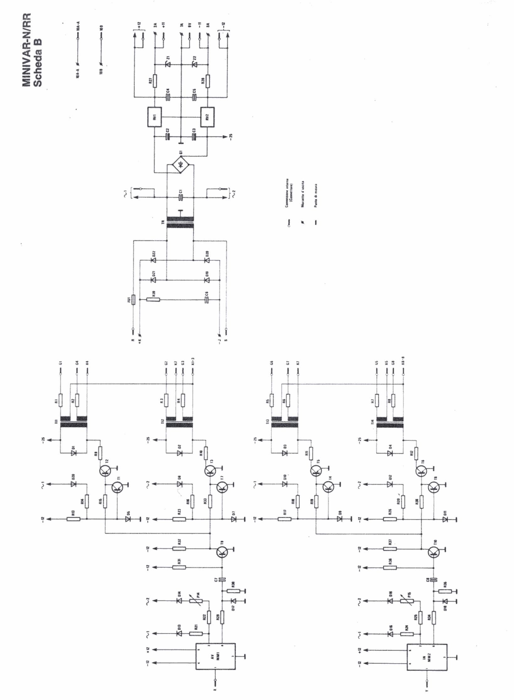
La diversa struttura di questa sezione è caratterizzata nella suddivisione delle varie serie: MINIVAR N/U ponte raddrizzatore di Graetz semicontrollato
(fig. 1A). MINIVAR N/R ponte raddrizzatore di Graetz totalcontrollato
(fig. 1B). MINIVAR N/RR doppio ponte raddrizzatore di Graetz
totalcontrollato connesso in antiparallelo (fig. 1C).
La serie MINIVAR N/U utilizza come trasduttore di corrente uno shunt in costantana mentre nella serie MINIVAR N/R e RR si utilizza un trasformatore amperometrico che permette la separazione galvanica dei circuiti di comando.
a. Power section
The various composition of this section is related to the different product series: MINIVAR N/U Graetz semi-controlled bridge rectifier (fig. 1A). MINIVAR N/R Graetz totally-controlled bridge rectifier(fig. 1B). MINIVAR N/RR Graetz double totally-controlled bridge rectifier
connected in anti-parallel (fig. 1C). The MINIVAR N/U series uses a constantan shunt as a current transducer while the MINIVAR N/R and RR series use an amperic transformer for the galvanic separation of the command circuits.
b. Sezione di comando
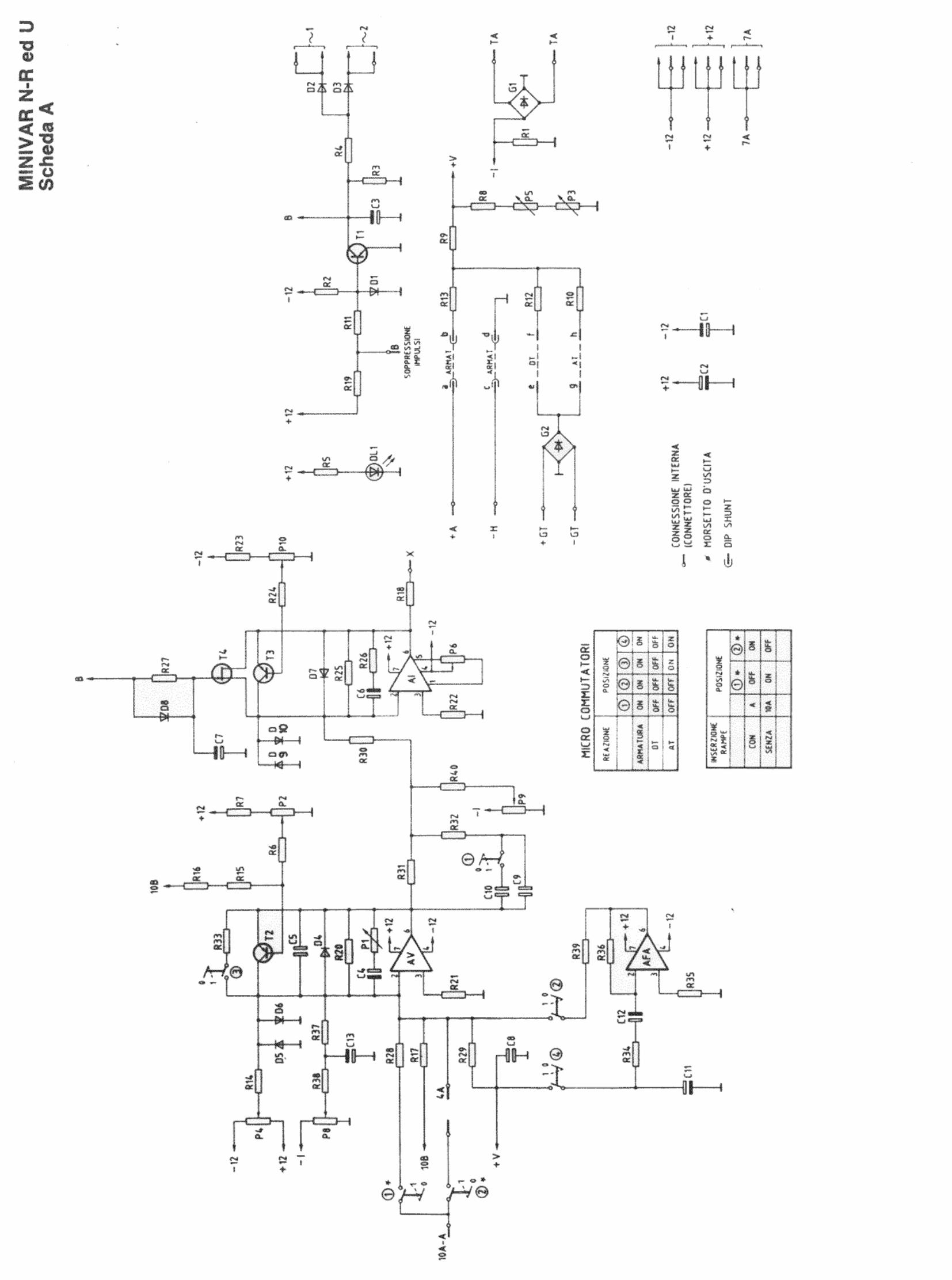
Nelle tre versioni U, R e RR è costituita da una scheda estraibile collegata tramite connettori al resto dell’apparecchio, permettendo perciò una facile sostituzione. Le schede di comando sono denominate rispettivamente: MINIVAR/N-A, MINIVAR/N-B, MINIVAR/N-RR/A e MINIVAR/N-RR/B.
b. Command section
In the U, R and RR versions, this is an extractable command card linked to the rest of the device by connectors so that it can be easily replaced. The various command cards are respectively called: MINIVAR/N-A, MINIVAR/N-B, MINIVAR/N-RR/A e MINIVAR/N-RR/B.
1. Scheda MINIVAR/N-A
E’ la vera e propria scheda di comando; in essa sono posti i principali sistemi di controllo e di regolazione dell’apparecchio. In esse sono anche presenti due serie di microinterruttori che controllano rispettivamente il tipo di reazione e l’inserimento delle eventuali rampe.
1. MINIVAR/N-A card
This is the actual command board and it contains the unit’s main control and adjustment systems. It also has two series of micro-switches which control reaction type and insertion of any ramp.
2. Scheda MINIVAR/N-B
E’ la scheda sottostante alla N-A; in essa sono posti tra l’altro i filtri, il ponte di Graetz di alimentazione dell’eccitazione, la morsettiera ed i fusibili posti a protezione dell’apparato.
2. MINIVAR/N-B card
This card is below the N-A card and contains the filters, the Graetz power supply bridge to exciter, the clamps and the fuses for machine protection.
3. Scheda MINIVAR/N-RR-A
E’ la scheda di comando della serie RR. In essa è presente un doppio stadio modulatore e tutti i circuiti di controllo delle grandezze controllate dal sistema. Anche in questa versione sono presenti due serie di microinterruttori che controllano il tipo di reazione e l’inserzione delle rampe.
3. MINIVAR/N-RR-A card
This is the command card used for the RR series. It contains a double stage modulator and all control circuits controlled by the system. This version has also two series of micro-switches which control reaction type and insertion of any ramp.
4. Scheda MINIVAR/N-RR-B
Vale quanto detto per la scheda MINIVAR/N-B con in più la possibilità di avere la separazione galvanica dei circuiti di comando impiegando un trasformatore amperometrico per il controllo della corrente.
4. MINIVAR/N-RR-B card
This contains al the features of the MINIVAR N-B card plus the possibility of galvanic separation of the command circuits using an amperic transformer for current control.
Schede opzionali
Sono dei circuiti supplementari che soddisfano particolari esigenze operative. Sono provviste di correttori estraibili che ne consentono una facile applicazione.
Optional cards
These are supplementary circuit boards for special operational requirements. They are fitted with extractable connectors for easy installation.
RA
Circuito di rampe di accelerazione e decelerazione. Consente di limitare al valore richiesto le accelerazioni e le decelerazioni, particolarmente utile su macchine a bassa costante di tempo. I valori di salita e discesa dei circuiti di rampe possono venire regolati separatamente mediante P1 e P2 posti sulla scheda stessa.
RA
Acceleration and deceleration ramps circuit. This provides limitation of pre-set acceleration and deceleration values, particularly useful on machine with low time constant. The rise and fall rates of the range circuits can be regulated independently using P1 and P2 on the cards themselves.
RA-C
E’ una scheda complementare alla precedente; è possibile abbinarla negli azionamenti reversibili serie MINIVAR/N-RR per ottenere 4 rampe regolabili separatamente per i due sensi di moto.
RA-C
A complementary circuit board to the one described above which can be coordinated with the MINIVAR/N-RR reversible drives to give 4 separately adjustable ramps for two drive directions.
SEN-1P
E’ una scheda con alimentazione 110/220V o 24/48V che dà la possibilità di predisporre 4 salti di velocità (2 avanti e 2 indietro) preimpostati tramite trimmer regolabili.
SEN-1P
This is a card with power supply at 110/220V or 24/48V that allows to set 4 speed jumps (2 forward and 2 backwards) by adjustable trimmers.
4
POSA IN OPERA Prima di procedere all’installazione, verificare lo stato dell’imballaggio e assicurarsi che l’apparecchio non abbia subito danni durante il trasporto. L’installatore dovrà attenersi scrupolosamente allo schema allegato per effettuare i collegamenti esterni rispettando, dove sono indicate, le polarità. Le sezioni dei conduttori da impiegare per i circuiti di potenza, linea ed armatura del motore devono essere adeguate alla corrente di targa del motore stesso. Per tutti gli altri conduttori usare la sezione minima di 1mmq. Le schermature indicate, in particolare quelle del potenziometro di velocità, sono da impiegarsi per sviluppi superiori a qualche metro e nei casi in cui questi conduttori passino in prossimità di altri che possano introdurre disturbi. Lo schermo va collegato a terra ad una sola estremità, mentre l’altra deve rimanere isolata. Il cavo schermato deve essere del tipo con guaina esterna isolante. E’ consigliabile installare l’apparecchio il più vicino possibile al motore comandato, evitando comunque ambienti inquinanti, aggressivi o polverosi. Assicurarsi che nessuna parte elettrica venga a contatto con la terra. Data la natura dei componenti impiegati, qualsiasi controllo d’isolamento e rigidità nell’impianto, motore compreso, deve effettuarsi ad apparecchio completamente scollegato. Prima di mettere l’apparecchio sotto tensione verificare che la tensione di linea sia quella prevista, che tutti i collegamenti siano stati eseguiti esattamente secondo lo schema, che i morsetti siano ben stretti e che non vi siano difetti d’isolamento sia fra conduttori che fra questi e la terra. Eseguito quanto sopra, portare il potenziometro di velocità a zero ed applicare la tensione di linea. Il motore deve rimanere fermo. Se gira alla massima velocità e ruotando il potenziometro in senso orario il motore si ferma gradualmente, occorre invertire i collegamenti ai terminali estremi del potenziometro di velocità 7A e 8A. Se viene impiegata la dinamo tachimetrica, per definirne la polarità basta applicare un tester con portata di bassa tensione continua ai suoi terminali e ruotare a mano il motore nel senso richiesto dalla macchina. Il terminale positivo andrà collegato al +D.T./+G.T. della morsettiera del MINIVAR N e l’altro al –D.T./-G.T. Se tutto non avvenisse come sopra descritto, consultare per eventuali avarie o difetti la “Guida per la ricerca dei guasti”. MANUTENZIONE Trattandosi di una macchina elettrica statica, il MINIVAR N non necessita di particolari cure. Tuttavia, un minimo di manutenzione preventiva assicura all’apparecchio una più lunga vita. Si raccomanda pertanto di eseguire periodicamente la pulizia dell’apparecchio mediante getto di aria compressa a bassa pressione e di verificare il buon serraggio dei morsetti d’allacciamento.
INSTALLATION Before proceeding with the installation, check the packaging and make sure that the equipment has not been damaged during transport. The installator must closely follow the enclosed scheme to realize the outside connection following the polarities, where specified. The conductor sections used for the power circuit, motor line and armature must be in compliance with the rating-plate current of the motor itself. For all the others conductors use the minimum section of 1 mm2. The shown shields, particularly those of the speed potentiometer, must be used for lengths greater than some meters or in cases in which these conductors run near other ones which can cause some interferences. The screen must be connected to ground at only one end, while the other one must be insulated. The screened cable must be with insulating outside sleeve. It is advisable to set up the equipment as near as possible to the driven engine, avoiding however pollutioned, aggressive and dusty environments. Make sure that no electric part is in contact with ground. Because of the used components, each insulation control and equipment rigidity (engine included) must be done with the equipment completely disconnected. Before connecting equipment to line it is necessary to verify that the line voltage is the scheduled one, that all the connections have been made exactly following the scheme, that the terminal blocks are well right and that there are no insulation defects either among conductors or between these ones and the ground. When you have accomplished all the above mentioned operations, place the speed potentiometer at position zero and connect the line voltage. The motor must remain stopped. If the motor runs to the maximum speed and turning the potentiometer in clock-wise direction the motor gradually stops, it is necessary to reverse the connections at the end terminals of the 7A and 8A speed potentiometer. If the tacho-dynamo is used, to define polarity apply a low voltage d.c. tester to its terminal blocks and hand-rotate the motor in the required direction of the machine. The positive end will be connected to the +D.T/+G.T. of the MINIVAR N terminal board and the other to the –D.T./-G.T. If such conditions are not satisfied, check for eventual failures or defects the “Direction for troubleshooting”. MAINTENANCE Being a static machine, the MINIVAR/N does not require any particular care. However, a minimum prior maintenance ensures the equipment a longer life. It is therefore recommended to effect periodical cleaning by low pressure air jet and to check the right tightness of the terminal board.
5
GUIDA PER LA RICERCA GUASTI Attenzione: Togliere tensione ai morsetti di linea RL-SL prima di intervenire sull’apparecchio. Scollegare tutti i conduttori dalla morsettiera prima di eseguire prove di isolamento sull’impianto.
TRACING OF BREAKDOWNS Caution: Cut off RL-SL line terminal voltage before touching the device. Disconnect all wires from the terminal board before putting the system to the insulation tests.
Difetto Causa probabile Rimedio Failure Probable cause Remedy
Intervento fusibili di potenza esterni (lampada “Rete” spenta).
Corto circuito o difetti d’isolamento fra i conduttori di potenza o fra questi e terra.
Per individuare il componente avariato da sostituire scollegare tutti i conduttori della morsettiera lasciando quelli di linea (RL/ SL), sostituire i fusibili e alimentare l’apparecchio. Se i fusibili non intervengono, la causa è da ricercarsi nell’impianto esterno, motore compreso. Se intervengono vuol dire che il convertitore ha uno o più diodi fuori servizio (corto circuito).
Power fuses external (Line LED off).
Short circuit or insulation lack between the power leads or between these ones and the ground.
In order to find out the damaged component to be changed, disconnect all the wires from the terminal board (but do not disconnect the wires of the RL-SL line), replace the fuses and give power to the device. If the fuses are not involved the cause must be looked for in the outside system, including the motor. If they burn out it means that the converter has one or several damaged diodes (short circuit).
Prova d’efficienza del convertitore con l’uso del tester posizionato su portata in Ohm per bassi valori. PROVA DIODO (un solo terminale): applicare un puntale del tester sulla custodia metallica e l’altro sul terminale dopo aver dissaldato il conduttore. Il diodo è efficiente se conduce in un senso e non conduce capovolgendo i puntali. Se conduce nei due sensi o se non conduce in nessun senso, il diodo è fuori servizio. PROVA DIODO CONTROLLATO (due terminali): eseguire la stessa prova facendo riferimento al terminale di potenza. Il diodo è fuori servizio se conduce in un senso e/o nell’altro.
Efficiency test of the converter by means of the tester at Ohm range for low values. DIODE TEST (one terminal only): apply one probe of the tester on the metal case and the other one on the terminal after having unsoldered the wire. The diode is efficient if it conducts current in one direction and if it does not inverting the probes. If it conducts current in both directions or in neither one, the diode is damaged. CONTROLLED DIODE TEST (two terminals): carry out the same test referring to the power terminal. The diode is damaged if it conducts current in one direction and/or in the other.
Varistore VDR fuori servizio (probabile intervento dei fusibili FU).
Allacciamento a rete con tensione più elevata di quella prescritta. Transtori di linea troppo elevati.
Sostituire VDR. L’apparecchio può funzionare anche senza protezione, tuttavia è indispensabile ripristinarlo per evitare danni maggiori. Il fuori servizio di questo componente è reso evidente dalla bruciatura superficiale.
Varistor VDR out of order (probably FU are burn out).
Connection on line at a too high voltage. Too high line transients.
Replace VDR. The device can work even without protections, however it is advisable to have them operating in order to avoid more serious damages. The breakdown of these components is made evident by the superficial burnout.
Intervento fusibili ausiliari FU (lampada “Rete” spenta).
Corto circuito o difetti d’isolamento fra i conduttori di eccitazione o fra questi e terra.
Scollegare i conduttori del circuito d’eccitazione dalla morsettiera, sostituire i fusibili e alimentare l’apparecchio. Se i fusibili non intervengono e si misura tensione fra i morsetti J e K, ricercare la causa nell’impianto esterno, motore compreso. Se intervengono o manca tensione fra J e K sostituire i diodi guasti del ponte d’eccitazione.
Auxiliary fuses FU are burnt out (Line RED off).
Short circuit or insulation lack between the excitation leads or between these ones and the ground.
Disconnect the excitation circuit leads from the terminal block, replace the fuses and give power to the device. If the fuses are not involved and there is voltage between the terminal blocks J and K, the cause must be looked for in the outside system, motor included. If they burn out or there is no voltage between J and K, it is necessary to replace the break diodes of the field bridge.
Trasformatore TR in corto circuito.
Sostituirlo.
Transformer in short circuit.
Replace it.
La macchina sotto carico non rimane stabile alla velocità programmata.
Potenziometro di velocità sporco o difettoso.
Sostituirlo.
The machine, when loadedr, is not stable at the planned speed.
Speed potentiometer dirty or damaged.
Replace the potentiometer.
Costanti di tempo non appropriate per quel tipo di carico meccanico. Eccessiva instabili-tà del rullo ballerino in asservimento di questo tipo. Brusche variazioni di carico nel funzionamento.
Intervenire sul potenziometro di stabilità “STABIL”. Qualora non si ottenessero i risultati desiderati si rende necessario un esame del sistema “macchina/ azionamento”.
The time constants are not suitable to the specific mechanical load. Excessive instability of the dandy roll for such system. There are abrupted variations of load during working.
Operate the stability potentiometer “STABIL.”. If the operation is not successful, it will be necessary to check the “machine-working” system.
6
Compound del motore E-F rove-sciata (instabilità più evidente ad alti giri del motore).
Controllare i collegamenti e le polarità del motore.
The compound of E-F motor is reversed (instability is more evident at a high speed of the motor).
Check motor connections and polarity.
La macchina non si avvia (tensione di eccitazione presente: LED verde acceso).
Potenziometro di velocità interrotto sul cursore 10A/A e/o terminale 8A.
Sostituirlo previo verifica delle connessioni.
The machine does not start (field voltage is present. Red LED off).
The speed potentiometer is disconnected on slider 10A/A and/or terminal 8A.
Replace the potentiometer after having checked the connections.
Corto circuito fra 8A e massa o fra 10A/A e massa. Probabile interru-zione delle piste relative a 8A e 10A/A. Fuori servi-zio di uno o più diodi Zener (Z1÷Z2) o del circuito integrato AV.
Sostituire la scheda. Short circuit between 10A/A and the ground. Break of the strip concerning 8A and 10A/A. One or more than one Z1÷Z2 diode Zener or the A-V integrated circuit is out of order.
Replace the card.
La macchina accelera troppo lentamente.
Manomessa la taratura di coppia max.
Riportare il potenziometro di coppia in posizione max come previsto in fase di taratura dal costruttore
The machine accelerates too slowly.
The calibration of maximum torque is alterated.
Reset the potentiometer of torque with the index indicating max, as planned by the constructor during the phase of calibration.
La rampa d’avviamento ha un tempo troppo lungo.
Intervenire sul trimmer salita (RA-C) sino a raggiungere il tempo di avviamento desiderato.
The response time of the starting ramp is too long.
Operate on trimmer (RA-C) in order to reach right response time.
Momento dinamico d’inerzia della macchina troppo elevato.
Ridimensionare la potenza installata tenendo conto dei sovraccarichi di avviamento necessari.
The machine has a too high dynamical moment of inertia.
Recalculate the power taking into account the necessary starting overloads.
La macchina accelera troppo bruscamente.
Rampa di avviamento con tempo troppo breve.
Intervenire sul trimmer salita (RA-C) sino a raggiungere il tempo di avviamento desiderato.
The machine accelerates too quickly.
The response time of the starting ramp is too short.
Operate on trimmer RA-C in order to reach the right response time.
Azionamento sovradimensionato per l’impiego richiesto.
Ridurre la coppia max. d’avviamento agendo sul trimmer “I max.” oppure ridimensionare l’azionamento.
Excessive power compared with the demanded utilization.
Reduce the maximum starting torque by operating on trimmer “I max.” or reduce the device.
Basso momento d’inerzia della macchina.
Adottare la scheda RA-C rampa di avviamento.
The machine has a too low dynamical moment of inertia.
Apply the printed board starting ramp “RA-C”.
Macchina ferma.
Sovratemperatura del regolatore.
Ventilare il quadro.
The machine is stopped.
Drive unit is overheated.
Check FV-1A.
Il motore si surriscalda.
Scarso dimensionamento.
Sostituire il motore oppure applicare la ventilazione forzata.
The motor becomes overheated.
Scarce dimensioning.
Replace the motor or apply forced ventilation.
Grippaggio meccanico.
Rimuovere l’ostacolo meccanico.
Mechanical seizure.
Remove the mechanical obstacle.
Eccessiva temperatura ambiente.
Ventilare il motore con aria fredda prelevata dall’esterno.
Ambient tempera- ture is too high.
Fan the motor with cold air coming from outside.
Eccessivo scintillio alle spazzole del motore.
Le spazzole sono consumate o non scorrono libera- mente nella loro sede.
Sostituirle o verificarne la scorrevolezza nel cassetto di guida.
The motor brush sparking is excessive.
Brushes are worn out or they do not slide freely in their slots.
Replace the brushes or check their smoothness in the slots.
Collettore sporco, consumato o ovalizzato.
Interpellare il costruttore del motore o un’officina specializzata
The collector is dirty, worn out or ovalized.
Consult the constructor of the motor or a specialized shop.
Arco portaspazzole non in zona neutra.
Interpellare il costruttore del motore o un’officina specializzata
The brushholder is not in a neutral zone.
Consult the constructor of the motor or a specialized shop.

7
La macchina non si avvia e l’aziona-mento è in limitazione.
Ostacolo meccanico.
Rimuovere l’ostacolo.
The machine does not start and the device is limited.
Mechanical obstacle.
Remove the obstacle.
Errore nel dimensionamento del motore o nei rapporti della macchina
Verificare e provvedere in merito. Wrong dimensio-ning of the motor or wrong gear ratio.
Check and take the appropriate measures.
Avvolgimento di campo interrotto.
Riparare il motore.
Field winding interrupted.
Repair the motor.
Circuito d’alimentazione avvolgimento di campo interrotto.
Controllare la tensione di eccitazione direttamente ai morsetti –J e +K del motore.
Feeding circuit of the field winding disconnected.
Control field voltage directly to the finals –J and +K of the motor.
La macchina non raggiunge la velocità nominale con potenziometro di velocità in posizione max.
Azionamento sovraccarico o scarso dimensionamento.
Verificare i calcoli di potenza e gli esatti rapporti meccanici.
The machine does not reach the nominal speed when the speed potentiometer indicates MAX.
Overload device. or scarce dimensioning.
Check the calculation of the power and the mechanical ratio.
Macchina operante a coppia notevolmente crescente con la velocità.
Assicurarsi della buona scorrevolezza e della buona lubrificazione di tutti gli organi mossi: cuscinetti, catene, cinghie, riduttori, ecc.
The machine works with a torque wihich increases too much when speed increases.
Check the smoothness and the lubrification of all the machine operating parts: bearings, chains, belts, reduction gears and so on.
Apparecchio non correttamente calibrato.
Agire sul trimmer max. vel. fino a raggiungere i giri di targa del motore, assicurandosi che anche la tensione d’armatura sia quella di targa.
The device is not correctly gauged.
Operate the maximum speed trimmer until it reaches the rating number of revolutions. Make sure that also the armature voltage is the rating one.
Un diodo controllato non si accende (il motore si surriscalda e diventa fortemente rumoroso).
Assicurarsi con l’oscilloscopio che fra i morsetti –H e +A manchi una semionda; di conseguenza provvedere alla sostituzione del diodo controllato difettoso o della scheda.
A controlled diode is not switched on (the motor is overheated and becomes very noisy).
Make sure, using the oscilloscope, that between the terminals –H and +A a half wave is omissing; consequently replace the damaged controlled diode.
La macchina si porta rapidamente alla massima velocità anche per posizioni intermedie del potenziometro di velocità.
Generatore tachi-metrico interrotto.
Sostituire.
The machine quickly reaches the maximum speed even when the speed potentiome-ter is at interme-diate positions.
The tacho-generator is disconnected.
Replace it.
Dinamo tachimetrica con polarità invertita.
Capovolgere i conduttori ai mor- setti –G.T./-D.T. e +G.T./+D.T.
The tacho-dynamo has a reverse polarity.
Upset the wires at the terminals –G.T./-D.T. and +G.T./+D.T.
Scorrimento nell’accoppiamento meccanico fra motore e genera-tore tachimetrico.
Stringere a fondo i grani dei due semigiunti.
Sliding in the mechanical coupling between the motor and the tacho-generator.
Tighten the screws of the two half-joints.
Tranciatura di uno dei due aberi che tramite il giunto danno il moto al generatore.
Sostituire il pezzo avariato controllando nel montaggio il buon allineamento.
One of the two half-joints, which through the joint drives the generator, is sheared.
Change the damaged component and check the alignment in the assembling.
Potenziometro di velocità interrotto sul terminal 7A.
Sostituire il potenziometro oppure ripristinare l’eventuale interruzione sul conduttore esterno 7A.
The speed potentiometer is disconnected on terminal 7A.
Change the potentiometer or remake the connection on the outside wire 7A.
Un diodo control-lato è sempre in conduzione (il mo- tore gira anche con potenziometro di velocità scollegato)
Provvedere alla sostituzione del diodo controllato difettoso.
A controlled diode is always in conduction (the motor runs with speed potentiome-ter disconnected)
Change the damaged controlled diode.

8
Corto circuito tra i due conduttori +G.T./+D.T. e -G.T./-D.T. o fra questi e massa.
Localizzare e isolare i conduttori.
Short circuit between the +G.T./+D.T. and –G.T./-D.T. wires or between these ones and the ground.
Locate and insulate the wires.
Probabile bruciatura delle piste relative 7A.
Se necessario sostituire la scheda completa.
Burnout of the traces concerning 7A.
If it is necessary, replace the printed-board or the trimmer P1.
La macchina sotto carico non rimane stabile alla velocità programmata.
Generatore tachimetrico non ben calettato.
Controllare l’accoppiamento meccanico tra generatore e motore.
The machine when loaded is not stable at the planned speed.
The tacho-generator is not well keyed.
Check the mechanical coupling between the generator and the motor.
Schema ponte semicontrollato (fig. 1A) semi-controlled bridge diagram
9
Schema ponte totalcontrollato (fig. 1B) totally-controlled bridge diagram Schema doppio ponte totalcontrollato connesso in antiparallelo (fig. 1C) Totally-controlled bridge connected in anti-parallel diagram

10
Morsettiera di allacciamento - Connection terminal board MINIVAR U-R
RL
SL
+A
-H
-J
+K
B
8A 10A
A
7A
-GT
+GT
RL Rete monofase RL Monophase supply SL Rete monofase SL Monophase supply +A Armatura +A Armature -H Armatura -H Armature -J Eccitazione -J Field +K Eccitazione +K Field B Soppressione impulsi B Pulses suppression 8A Riferimento (-11V) 8A Datum (-11V) 10A/A Ingresso segnale 10A/A Signal input 7A Riferimento (0V) 7A Datum (0V) - G.T. Generatore tachimetrico - G.T. Tacho-generator +G.T. Generatore tachimetrico +G.T Tacho-generator MINIVAR-N/RR
RL
SL
+A
-H
S
-J
+K
2A
7A 10A
A
8A
10B
-DT
+DT
RL Rete monofase RL Monophase supply SL Rete monofase SL Monophase supply +A Armatura +A Armature -H Armatura -H Armature -J Eccitazione -J Field +K Eccitazione +K Field 2A Riferimento (+11V) 2A Datum (+11V) 7A Riferimento (0V) 7A Datum (0V) 10A/A Ingresso segnale 10A/A Signal input 8A Riferimento (-11V) 8A Datum (-11V) 10B Ingresso supplementare 10B Additional signal input - D.T. Dinamo tachimetrica - D.T. Tacho-generator +D.T. Dinamo tachimetrica +D.T. Tacho-generator S Abilitazione esterna impulsi S External pulse abilitation MINIVAR-N/RR Schema elettronico generale


17

18
NOTE:

19
NOTE:

MIPRO s.r.l.
MIPRO s.r.l.
ELETTROQUADRI
LINEA DI PRODUZIONE PRODUCTS RANGE GAMME DE PRODUCTION PRODUKTIONSREIHE
REGOLATORI DI VELOCITÀ SERVODRIVES REGULATEURS DE VITESSE GESCHWINDIGKEITSREGLER a S.C.R., transistors o IGBT per motori c.a., c.c. e brushless; inverters.
S.C.R., transistors or IGBT types for a.c., d.c. and brushless motors, inverters.
à S.C.R., transistor ou IGBT pour moteurs en c.a., c.c. et brushless; inverseurs.
mit S.C.R., Transistor oder IBGT für Wechselstrom-, Gleichstrom- und Brushlessmotoren; Wechselrichter.
MOTORI MOTORS MOTEURS MOTOREN c.a., c.c., a magneti permanenti e brushless con relativi accessori.
a.c., d.c., permanent magnet and brushless motors, including the accessories.
en c.a., c.c., à aimants permanents et brushless avec accessoires.
Gleichstrom-, Wechselstrom-, Dauermagnet- und Brushlessmotoren mit Zubehör.
SISTEMI COMPLETI PLANT MOTION CONTROL SYSTEMS
SYSTEMES COMPLETES VOLLSTÄNDIGE SYSTEME
per l’automazione industriale. tailor-made for industrial automation.
pour l’automatisation industrielle.
Komplette Antriebs-Systeme für die Industrieautomatisierung.
FILTRI FILTERS FILTRES FILTER monofase e trifase a doppia cella conformi alle normative EMC.
single-phase and three-phase filters at double cell in compliance with EMC regulations.
monophasés et triphasés à double chambre conformes aux normes EMC.
einphasige und dreiphasige Filter mit doppelter Zelle gemäß der EMC-Vorschriften.
QUADRISTICA PANELS TABLEAUX SCHALTTAFELN progettazione e realizzazione quadristica di comando e di controllo, anche per la distribuzione industriale.
design and realization of control panels, also for the industrial distribution.
projet et réalisation de tableaux de commande et de contrôle, aussi pour la distribution industrielle.
Entwurf und Herstellung von Steuerschalttafeln, auch für die Industrieverteilung.
IMPIANTI INDUSTRIALI INDUSTRIAL PLANTS INSTALLATIONS INDUSTRIELLES INDUSTRIEANLAGEN CABLAGGI A BORDO MACCHINA. WIRING ON MACHINES CABLAGES DES MACHINES MASCHINENVERDRAHTUNGE
N
MIPRO S.r.l.
Tel. 0362/57.11.33 r.a. Fax 0362/57.11.35 – Indirizzo e-mail: [email protected]
ELETTROQUADRI GUIZZO
Tel. 0362/55.99.29 – Fax 0362/59.07.42 – Indirizzo e-mail: [email protected]
Via del Lavoro, 14 – 20030 BOVISIO MASCIAGO (Milano) - ITALY