Embed Size (px)
Citation preview
US 20040077771A1
(12) Patent Application Publication (10) Pub. No.: US 2004/0077771 A1 (19) United States
Wadahara et al. (43) Pub. Date: Apr. 22, 2004
(54) CARBON FIBER REINFORCED RESIN COMPOSITION, MOLDING COMPOUNDS AND MOLDED ARTICLE THEREFROM
(76) Inventors: Eisuke Wadahara, Ehime (JP); Masato Honma, Ehime (JP); Soichi Ishibashi, Ehime (JP); Yasunori Nagashima, Ehime (JP); Yuji Kojima, Ehime (JP)
Correspondence Address: Barry E Bretschneider Morrison & Foerster Suite 300 1650 Tysons Boulevard McLean, VA 22102 (US)
(21) Appl. No.: 10/470,975
(22) PCT Filed: Feb. 2, 2002
(86) PCT No.: PCT/JP02/00847
(30) Foreign Application Priority Data
Feb. 5, 2001 (JP) ....................................... .. 2001-28179
Feb. 9, 2001 (JP) ....................................... .. 2001-33462
Feb. 9, 2001 (JP) ....................................... .. 2001-33463
Publication Classi?cation
(51) Int. Cl? ..................................................... ..C08K 3/04 (52) Us. 01. ............................................................ ..524/495
(57) ABSTRACT
The present invention relates to carbon ?ber reinforced resin compositions comprising the following essential compo nents (A), (B) and (C), and to molding compounds and molded products made by processing and molding the carbon ?ber reinforced resin composition; Component (A): 0.01 to 0.7% by Weight of vapor groWn carbon ?ber and/or nanotubes based on 100% by Weight of the carbon ?ber reinforced resin composition, of Which the average diameter of single ?ber ranges from 1 to 45 nm; Component (B): 6 to 40% by Weight of carbon ?ber based on 100% by Weight of the carbon ?ber reinforced resin composition, of Which the average diameter of single ?ber ranges from 1 to 20 pm; and Component (C): resin. The present invention provides car bon ?ber reinforced resin composition, molding compounds and molded products therefrom, having good conductivity, mechanical properties and moldability by the above consti tution.
Patent Application Publication Apr. 22, 2004 Sheet 1 0f 4 US 2004/0077771 A1
Fig. 1
Fig. 2
Patent Application Publication Apr. 22, 2004 Sheet 2 0f 4 US 2004/0077771 A1
Fig. 3
Fig. 4
Patent Application Publication Apr. 22, 2004 Sheet 3 0f 4 US 2004/0077771 A1
Fig. 5 .
Fig. 6
Patent Application Publication Apr. 22, 2004 Sheet 4 0f 4 US 2004/0077771 A1
Fig. 7
US 2004/0077771 A1
CARBON FIBER REINFORCED RESIN COMPOSITION, MOLDING COMPOUNDS AND
MOLDED ARTICLE THEREFROM
FIELD OF THE INVENTION
[0001] The present invention relates to carbon ?ber rein forced resin compositions, molding compounds and molded products therefrom, having good conductivity, mechanical properties and moldability.
BACKGROUND OF THE INVENTION
[0002] Resin compositions having desired conductivity by blending resin With conductive materials (eg carbon ?bers) are knoWn. Recently, various attempts have been made, such as increase in amount of blended conductive materials, use of particular conductive materials, combination of several conductive materials and the like, to achieve higher con ductivity. [0003] The increase in amount of blended conductive materials to achieve higher conductivity, hoWever, gave rise to some problems in many cases such as high viscosity of the composition, large curtailment of mechanical properties, such as impact strength, deterioration of outer surface appearance of the molded products and the like.
[0004] One example of the use of particular conductive materials is blending resin With vapor groWn carbon ?ber, a nanotube and the like. Such technologies Were disclosed in, for example, Japanese Patent Laid-open No. (Hei) 7-102112 and WO-2000-050514. HoWever, these particular conduc tive materials are very expensive. Furthermore, considerable amount of these materials must be blended to achieve high conductivity With these materials alone. Accordingly, the price of the resin composition becomes expensive.
[0005] One example of the combination of several con ductive materials is to combine carbon black With conduc tive ?ber. Such technologies Were disclosed in, for example, US. Pat. No. 4,604,413 and Japanese Patent Laid-open No. (Hei) 6-240049. These technologies can increase conduc tivity of conventional resin to some degree but deteriorates moldability (for example, ?oWability When molding) and mechanical properties. Therefore, they could not satisfy high conductivity and moldability simultaneously.
[0006] Another example of the combination of several conductive materials is to combine carbon ?ber With par ticular small diameter carbon ?ber (e.g. vapor groWn carbon ?ber). Such technologies Were disclosed in, for example, US. Pat. No. 5,643,502 and Japanese Patent Laid-open No. 2000-44815. According to the above publications, hoWever, it Was found that some resin compositions having certain ratio of carbon ?ber and small diameter carbon ?ber does not increase conductivity and, in some cases, even loWers con ductivity. Thus, it is clear that the above technologies cannot give good results.
[0007] Carbon ?ber reinforced resin compositions are frequently used for various member of electronic devices, such as personal computers, of?ce automation devices, AV devices, mobile phones, telephones, facsimile machines, household appliances, toys and the like because of their high shielding property against electromagnetic Waves and good mechanical properties. Recently, With the development of portable devices, the thickness of the casing as Well as the
Apr. 22, 2004
inner parts of the devices have to be small, Which results in strong requirements for conductivity, mechanical properties, and moldability. Therefore, deterioration of such character istic features becomes critical.
[0008] Given the above technologies, it Was impossible to prepare carbon ?ber reinforced resin composition, molding compounds and molded products therefrom that had high conductivity, shoW high shielding property against electro magnetic Waves and satisfy moldability such as ?oWability When molding and ease of molding.
[0009] Purpose of the Invention
[0010] The present invention is intended to provide carbon ?ber reinforced resin compositions, molding compounds and molded products therefrom, having good conductivity, mechanical properties and moldability, beyond the above conventional technologies.
[0011] Disclosure of the Invention
[0012] The present invention is based on investigation to solve problems in conventional technologies and the ?nding that carbon ?ber reinforced resin compositions made by blending carbon ?ber With particular small diameter carbon ?ber in a speci?c ratio produces good results.
[0013] The carbon ?ber reinforced resin compositions of the present invention have the folloWing essential compo nents:
[0014] Component (A): 0.01 to 0.7% by Weight of vapor groWn carbon ?ber and/or nanotubes based on 100% by Weight of the carbon ?ber reinforced resin composition, of Which the average diameter of single ?ber ranges from 1 to 45 nm;
[0015] Component (B): 6 to 40% by Weight of carbon ?ber based on 100% by Weight of the carbon ?ber reinforced resin composition, of Which the average diameter of single ?ber ranges from 1 to 20 pm; and
[0016] Component (C): resin.
[0017] The molding compounds and the molded products of the present invention are characteriZed in that they are made by processing and molding said carbon ?ber rein forced resin composition.
BRIEF DESCRIPTIONS OF THE DRAWINGS
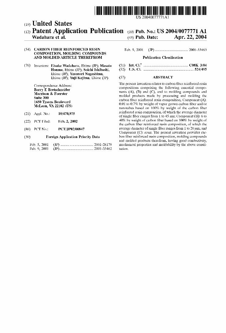
[0018] FIG. 1 is a cross-sectional vieW of an example con?guration of the molding compounds according to the present invention.
[0019] FIG. 2 is a cross-sectional vieW of another example con?guration of the molding compounds according to the present invention that is different from the example of FIG. 1.
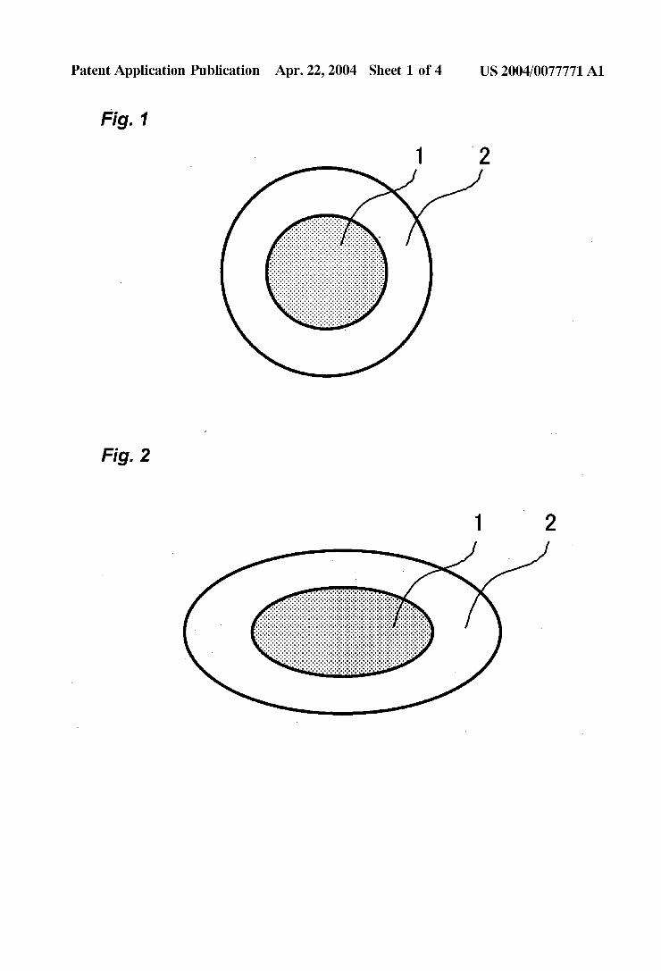
[0020] FIG. 3 is a cross-sectional vieW of another example con?guration of the molding compounds according to the present invention that is different from the example of FIG. 1.
[0021] FIG. 4 is a cross-sectional vieW of another example con?guration of the molding compounds according to the present invention that is different from the example of FIG. 1.
US 2004/0077771 A1
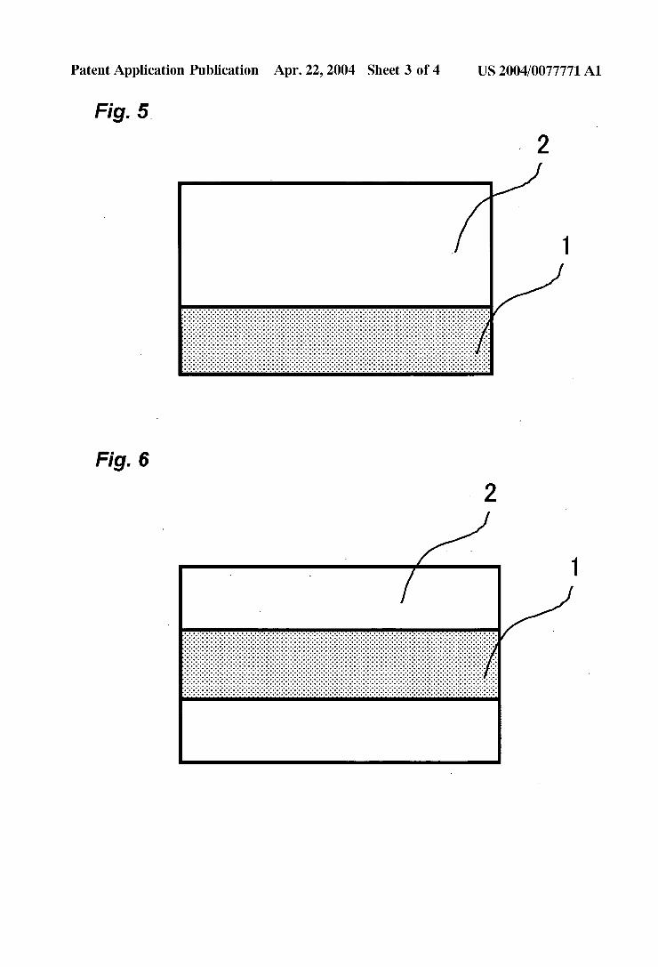
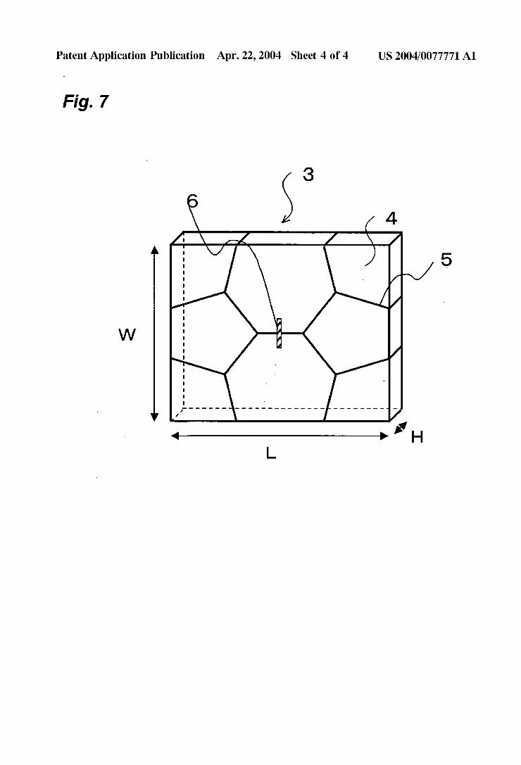
[0022] FIG. 5 is a cross-sectional vieW of another example con?guration of the molding compounds according to the present invention that is different from the example of FIG. 1.
[0023] FIG. 6 is a cross-sectional vieW of another example con?guration of the molding compounds according to the present invention that is different from the example of FIG. 1.
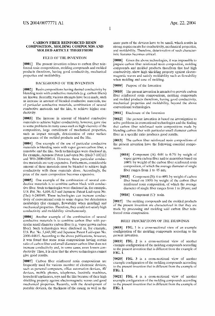
[0024] FIG. 7 is a perspective-vieW of a model casing for electronic devices used in the examples of the present invention.
DESCRIPTIONS OF FIGURE REFERENCES
[0025] 1: Structure B containing component (B) as a main component
[0026] 2: Structure A containing component (C) as a main component
[0027] 3: Model casing for electronic devices
[0028] 4: Top surface
[0029] 5: Weld line
[0030] 6: Measurement range of outer surface appearance
[0031] L: Length
[0032] W: Width
[0033] H: Height
[0034] Preferred Embodiments of the Present Invention
[0035] The preferred embodiments of the carbon ?ber reinforced resin composition of the present invention Will be speci?cally explained beloW.
[0036] The carbon ?ber reinforced resin composition of the present invention is comprised of at least folloWing components (A), (B) and (C):
[0037] Component (A): 0.01 to 0.7% by Weight of vapor groWn carbon ?ber and/or nanotubes based on 100% by Weight of the carbon ?ber reinforced resin composition, of Which the average diameter of single ?ber ranges from 1 to 45 nm;
[0038] Component (B): 6 to 40% by Weight of carbon ?ber based on 100% by Weight of the carbon ?ber reinforced resin composition, of Which the average diameter of single ?ber ranges from 1 to 20 pm; and
[0039] Component (C): resin.
[0040] Component (A) of the present invention de?nes carbon ?ber or graphite ?ber Which is generally discontinu ous and obtained by a vapor deposition method Which groWs crystal in the vapor phase and/or single-layer or multi-layer nanotubes obtained by a vapor deposition method, arc discharge method, laser evaporation method and the like. These can be any shape such as a needle, a coil and a tube. Additionally, at least tWo of these can be blended. Aprocess for preparing component (A) Was disclosed in US. Pat. No. 5,643,502, but is not limited thereto.
[0041] Shinohara et al. reported usage of poWdery Y-type Zeolite supported cobalt and vanadium in a process for preparing multi-layer nanotubes by vapor deposition method
Apr. 22, 2004
(Chemical Physics Letters, 303:117-124, 1999). This is useful for preparing a cheap, narroW and good nanotube.
[0042] Plasma treatment can be performed to increase dispersity and ease in handling of the nanotube. An example of a plasma treatment is loW temperature plasma treatment that is knoWn in the art, although not limited thereto. This is a process Whereby a nanotube and a treating gas are placed in plasma treating area and then treating the nanotube With plasma generated by application of high voltage. Examples of treating gases include organic or inorganic gases although not limited thereto, such as oxygen, nitrogen, hydrogen, ammonia, methane, ethylene, tetra?uorocarbon, and mixture thereof Oxygen gas plasma treatment is particularly pre ferred to improve the handling ease of a nanotube.
[0043] The average diameter of single ?ber of component (A) is in the range of 1 to 45 nm, preferably 5 to 35 nm, more preferably 7 to 30 nm, and particularly preferably 9 to 25 nm. If the average diameter of single ?ber is less than 1 nm, it is sometimes dif?cult to prepare in the ?ber form. On the other hand, if the average diameter of single ?ber is more than 45 nm, it is sometimes impossible to get speci?cally desired conductivity.
[0044] Average aspect ratio of component (A) preferably ranges from 1 to 10000 and particularly from 20 to 5000, because conductivity increases effectively at these ranges.
[0045] The preferable amount of component (A) ranges from 0.01 to 0.7% by Weight based on 100% by Weight of the carbon ?ber reinforced resin composition. It ranges more preferably from 0.05 to 0.6% by Weight, particularly pref erably from 0.1 to 0.45% by Weight and most preferably from 0.15 to 0.35% by Weight. If the amount of component (A) is less than 0.01% by Weight, it is sometimes impossible to get desired conductivity. On the other hand, if the amount of component (A) is more than 0.7% by Weight, the ?oWability of the carbon ?ber reinforced resin composition deteriorates extremely, Which sometimes results in loWer conductivity than the conductivity of the resin composition of component (B) alone Without component The dete rioration of ?oWability curtails moldability, Which is avoided by the present invention, and also accelerates cut or breakage of component (B), thereby remarkably degrading the mechanical properties or impairing outer surface appear ance, for example uneven defects in the surface of the molded products. These phenomena are critical shortcoming in member for electronic devices.
[0046] Component (B) of the present invention de?nes carbon ?ber or graphite ?ber made from PANs, pitches and the like; metal-coated carbon ?ber made by coating the above carbon ?ber or graphite ?ber With at least one layer of metal such as nickel, ytterbium, gold, silver, cupper and the like using plating (electrolysis or electroless), CVD, PVD, ion plating, vapor deposition and the like; and a combination of at least tWo thereof. When at least tWo of the above are combined, carbon ?ber can be combined With ?ber other than carbon ?ber such as glass ?ber or aramid ?ber. PAN type carbon ?ber is preferable for such carbon ?ber because it has good balance betWeen price and mechanical properties such as strength and modulus.
[0047] Carbon ?ber With crystalline siZe measured by Wide-angle X-ray diffraction (hereinafter, referred to as “Lc”) to be in the range of 1 to 6 nm is preferable for the
US 2004/0077771 A1
carbon ?ber used in the present invention. If the crystalline siZe is less than 1 nm, the conductivity of the carbon ?ber is loW, because carboniZation or graphitiZation of the carbon ?ber is not suf?cient. Therefore, the conductivity of the molded products Will also be loW. On the other hand, if the crystalline siZe is more than 6 nm, the carbon ?ber is Weak and easy to break although the carboniZation or graphitiZa tion of the carbon ?ber is sufficient and so the conductivity of the carbon ?ber itself is good. Consequently, the length of the carbon ?ber in the molded products is short, and, thus, good conductivity of the molded products cannot be eXpected. The crystalline siZe ranges more preferably from 1.3 to 4.5 nm, particularly preferably from 1.6 to 3.5 nm, and most preferably from 1.8 to 2.8 nm. Measurement of Lc by Wide-angle X-ray diffraction Was performed according to the method described in available reference materials (Japan Society for the promotion of science, panel 117, carbon, 36, p 25 (1963)).
[0048] The average diameter of a single ?ber of compo nent (B) is in the range of 1 to 20 pm. The diameter preferably ranges from 4 to 15 pm, more preferably from 5 to 11 pm, and particularly preferably from 6 to 8 pm. If the average diameter of a single ?ber is less than 1 pm, it is sometimes impossible to obtain the desired mechanical properties. On the other hand, if the average diameter of a single ?ber is more than 20 pm, it is sometimes impossible to obtain the particularly desired conductivity.
[0049] The amount of component (B) ranges preferably from 6 to 40% by Weight, more preferably from 8 to 37% by Weight, particularly preferably from 12 to 35% by Weight and most preferably from 17 to 32% by Weight. If the amount of component (B) is less than 6% by Weight, it is sometimes impossible to get speci?cally desired conductiv ity or mechanical properties. On the other hand, if the amount of the component (B) is more than 40% by Weight, moldability becomes bad because ?oWability When molding deteriorates, and the outer surface appearance of the molded products also deteriorates.
[0050] Any thermosetting resin or thermoplastic resin can be used for component (C) of the present invention. Ther moplastic resin is more preferable because the impact strength of the molded products therefrom is good and the molded products can be made by effective molding process such as press molding and injection molding.
[0051] The thermosetting resin includes, for instance, unsaturated polyester, vinyl ester, epoXy, phenol (resol type), urea.melamine, polyimide and the like, copolymers, modi ?cations, and combinations thereof. Moreover, elastomer or rubber can be added to the above thermosetting resin to improve the impact strength.
[0052] The thermoplastic resin includes, for instance, polyesters such as polyethylene terephthalate (PET), poly butylene terephthalate (PBT), polytrimethylene terephtha late (PTT), polyethylene naphthalate (PEN), liquid crystal line polyester and the like; polyole?nes such as polyethylene (PE), polypropylene (PP), polybutylene and the like; sty renic resin; polyoXymethylene (POM); polyamide (PA); polycarbonate (PC); polymethylenemethacrylate (PMMA); polyvinyl chloride (PVC); poly(phenylenesul?de) (PPS); polyphenylene ether (PPE); modi?ed PPE; polyimide (PI); polyamideimide (PAI); polyetherimide (PEI); polysulfone (PSU); polyethersulfone; polyketone (PK); polyetherketone
Apr. 22, 2004
(PEK); polyetheretherketone (PEEK); polyetherketoneke tone (PEKK); polyarylate (PAR); polyethernitrile (PEN); phenolic resin; phenoXy resin; ?uorinated resin such as polytetra?uoroethylene; thermoplastic elastomers such as polystyrene type, polyole?n type, polyurethane type, poly ester type, polyamide type, polybutadiene type, polyiso prene type, ?uoro type and the like; copolymers thereof; modi?cations thereof; and combinations thereof. Moreover, other elastomer or rubber can be added to the above ther moplastic resin to improve the impact strength.
[0053] From the aspect of moldability, economical ef? ciency, mechanical properties and heat resistance, at least one thermoplastic resin selected from the group consisting of polyamide resin, styrenic resin, polycarbonate resin, polyphenylene ether resin, polyester resin, poly (phenylene sul?de) resin, polyole?n resin, liquid crystal resin, phenolic resin and elastomer is preferable. At least one thermoplastic resin selected from the group consisting of polyamide resin, polycarbonate resin, styrenic resin and polyester resin is particularly preferable. Particularly, if phenolic resin is jointly used, improvements in moldability can be achieved.
[0054] The polyamide resin is a polymer With main com ponents comprised of amino acid, lactam or diamine and dicarboXylic acid. The speci?c eXamples are amino acids such as 6-aminocaproic acid, 11-aminoundecanoic acid, 12-aminododecanoic acid, p-aminomethylbenZoic acid and the like; lactams such as e-caprolactam, uu-laurolactam and the like; aliphatic, alicyclic or aromatic diamines such as tetramethylenediamine, heXamethylenediamine, 2-methyl pentamethylenediamine, nonamethylenediamine, undecam ethylenediamine, dodecamethylenediamine, 2,2,4-trimeth ylheXamethylenediamine, 2,4,4 trimethylheXamethylenediamine, 5 -methylnonamethylenediamine, metaXylylenediamine, paraXylylenediamine, 1,3-bis(aminomethyl)cycloheXane, 1,4-bis(aminomethyl)cycloheXane, 1-amino-3-aminom ethyl-3,5,5-trimethylcycloheXane, bis(4-aminocycloheXyl )methane, bis(3-methyl-4-aminocycloheXyl)methane, 2,2 bis(4-aminocycloheXyl)propane, bis(aminopropyl)piperaZine, aminoethylpiperaZine and the like; aliphatic, alicyclic or aromatic dicarboXylic acid such as adipic acid, suberic acid, aZelaic acid, sebacic acid, dodecanoic diacid, terephthalic acid, isophthalic acid, 2-chloroterephthalic acid, 2-methylterephthalic acid, 5-me thylisophthalic acid, 5-sodium-sulfoisophthalic acid, 2,6 naphthalene dicarboXylic acid, heXahydroterephthalic acid, heXahydroisophthalic acid and the like; and homopolymers or copolymer derived therefrom.
[0055] The speci?c eXamples of useful polyamide resins are polycaproamide (Nylon 6), polyheXamethyleneadipam ide (Nylon 66), polytetramethyleneadipamide (Nylon 46), polyheXamethylenesebacamide (Nylon 610), polyheXam ethylenedodecamide (Nylon 612), polyundecaneamide, polydodecaneamide, heXamethyleneadipamide/caproamide copolymer (Nylon 66/6), caproamide/heXamethylenetereph thalamide copolymer (Nylon 6/6T), heXamethyleneadipam ide/heXamethyleneterephthalamide copolymer (Nylon 66/6T) heXamethyleneadipamide/heXamethyleneisophthala mide copolymer (Nylon 66/6I), heXamethyleneadipamide/ heXamethyleneisophthalamide/caproamide copolymer (Nylon 66/6I/6), heXamethyleneadipamide/heXamethylene terephthalamid/carpoamide copolymer (Nylon 66/6T/6), heXamethyleneterephthalamide/heXamethyleneisophthala
US 2004/0077771 A1
mide copolymer (Nylon 6T/6I), heXamethyleneterephthala mide/dodecanamide copolymer (Nylon 6T/12), heXameth yleneadipamide/heXamethyleneterephthalamide/ heXamethyleneisophthalamide copolymer (Nylon 66/6T/6I), polyXylyleneadipamide, heXamethyleneterephthalamide/2 methylpentamethyleneterephthalamide copolymer, poly metaXylylenediamineadipamide (Nylon MXD6), polynon amethyleneterephthalamide (Nylon 9T) and mixtures thereof.
[0056] Particularly, if polyamide resin With melting tem perature equal to or above 150° C. is used, good modulus, impact strength, heat resistance or chemical resistance can be obtained. When polyamide is used for production of member for electronic devices, hoWever, polyamide copoly mer resin is preferable because it enables production of molded products having complex shape With large projected area and small thickness With relatively cheap molding process such as injection molding. Among these, the fol loWing polyamide resins are particularly preferable.
[0057] Nylon 66/61/6 copolymer comprising at least (pa1) heXamethylenediamineadipamide unit, (pa2) heXamethyl eneisophthalamide unit and (pa3) carpoamide unit is pref erably used. The preferred ratio of the amounts of those units is as folloWs: component (pa1) being in the range of 60 to 90% by Weight and particularly 70 to 85% by Weight; component (pa2) being in the range of 1 to 30% by Weight and particularly 10 to 20% by Weight; and component (pa3) being in the range of 1 to 10% by Weight and particularly 3 to 8% by Weight. The preferred ratio of (pa2)/(pa3) by Weight ranges from 1 to 30 and particularly 1.5 to 20. If such preferred polyamide resins are used, the results are good conductivity, smoothness in the Welding portion (Weld line) at Which the resins are contacted With one another When molding the composition, and good mechanical properties (especially, modulus) under moisturiZed condition.
[0058] The smoothness of the Welding portion is desired for increased productivity and economical ef?ciency When producing molded products such as member for electronic devices. The good mechanical properties under moisturiZed condition are desired for practical strength When the molded products are used under adverse conditions such as high temperature and high humidity. [0059] The preferred standard of the molecular Weight of the polyamide resins in vieW of moldability is relative viscosity, and relative viscosity measured in sulfuric acid of 1% concentration at 25° C. is from 1.5 to 2.5 and preferably from 2.0 to 2.3, although not particularly limited thereto.
[0060] The polyamide copolymer resins are preferably used as main component of component HoWever, it can be combined With other polyamide resins according to particular demand.
[0061] According to the need for improvement of charac teristic features such as impact resistance, one or more selected from the group consisting of maleic anhydride modi?ed ole?n polymers; styrenic copolymers such as ABS and ASA; and elastomers such as polyesterpolyether elas tomer and polyesterpolyester elastomer can be added to the polyamide resins.
[0062] The styrenic resins used in the present invention include a unit generated from styrene and/or derivatives thereof (sometimes referred to as aromatic vinyl monomers, as a Whole).
Apr. 22, 2004
[0063] Such styrenic resins include styrenic (co)polymer and rubber reinforced styrenic (co)polymer. The styrenic (co)polymer includes polymer generated from one or more aromatic vinyl monomers, and copolymer generated from one or more aromatic vinyl monomers and one or more
monomers that are copolymeriZable With the aromatic vinyl monomers. The rubber reinforced styrenic (co)polymer includes (co)polymer comprising styrene monomer grafted to the rubbery polymer and (co)polymer comprising styrene monomer not grafted to the rubbery polymer.
[0064] The preferred styrenic resin of the present inven tion includes styrenic polymer such as PS (polystyrene), rubber reinforced styrenic polymer such as HIPS (high impact polystyrene), styrenic copolymer such as AS (acry lonitrile/styrene copolymer), rubber reinforced styrenic copolymer such as AES (acrylonitrile/ethylene propylene unconjugated diene rubber/styrene copolymer), ABS (acry lonitrile/butadiene/styrene copolymer), MBS (methyl meth acrylate/butadiene/styrene copolymer), ASA (acrylonitrile/ styrene/acrylic rubber copolymer). Among these, styrenic resin such as PS (polystyrene), styrenic copolymer such as AS (acrylonitrile/styrene copolymer), ABS (acrylonitrile/ butadiene/styrene copolymer) and ASA (acrylonitrile/sty rene/acrylic rubber copolymer) are more preferable.
[0065] The polycarbonate resin used in the present inven tion includes aromatic polycarbonate, aliphatic polycarbon ate, alicyclic polycarbonate and aromatic-aliphatic polycar bonate. Among these, aromatic polycarbonate is preferable.
[0066] The aromatic polycarbonate resin is polymer or copolymer obtained by reacting carbonate precursor With aromatic hydroXy compound or small amount of polyhy droXy compound and the aromatic hydroXy compound. The method for producing aromatic polycarbonate resin is not particularly limited and includes the Widely knoWn phos gene method and transester?cation method.
[0067] The aromatic hydroXy compound includes 2,2 bis(4-hydroXyphenyl)propane (generally called as bisphenol A), 2,2-bis(4-hydroXyphenyl)methane, 1,1-bis(4-hydroX yphenyl)ethane, 1,1-bis(4-hydroXyphenyl)cycloheXane, 2,2 bis(4-hydroXy-3,5-dimethylphenyl)propane, 2,2-bis(4-hy droXy-3,5-dibromophenyl)propane, 2,2-bis (hydroXy-3 methylphneyl)propane, bis(4-hydroXyphenyl)sul?de, bis(4 hydroXy-phenyl)sulfone, hydroquinone, resorcinol, 4,6 dimethyl-2,4,6-tri(4-hydroXyphenyl) heptene, 2,4,6 dimethyl-2,4,6-tri(4-hydroXyphenyl)heptane, 2,6-dimethyl 2,4,6-tri(4-hydroXyphenyl)heptene, 1,3,5-tri(4 hydroXyphneyl)benZene, 1,1,1-tri(4-hydroXyphenyl) ethane, 3,3-bis(4-hydroXyaryl)oXyindole, 5-chloro-3,3-bis(4-hy droXyaryl)oXyindole, 5,7-dichloro-3,3-bis(4-hydroXyary l)oXyindole, 5-brome-3,3-bis(4-hydroXyaryl) oXyindole and the like. TWo or more of these can be combined. Among these, bis(4-hydroXyphenyl)alkane is preferable, and bisphe nol A is particularly preferable.
[0068] In order to provide ?ame retardancy, the aromatic dihydroXy compound to Which is bonded at least one sul fonic acid tetraalkylphosphonium or an oligomer or polymer having a siloXane structure, containing a phenolic hydroXy group at both ends can be used.
[0069] For the carbonate precursor, carbonylhalide, car bonate ester or haloformate and the like can be used. Speci?cally, phosgene, diphenylcarbonate and the like can be used.
US 2004/0077771 A1
[0070] The molecular Weight of the polycarbonate resin ranges preferably from 14,000 to 30,000, more preferably from 15,000 to 28,000, and particularly preferably from 16,000 to 26,000 measured by viscosity average molecular Weight in vieW of mechanical properties of the molded products and moldability. Wherein, the viscosity average molecular Weight is calculated from the solution viscosity measured at a temperature of 25° C. using a 0.7 g carbonate resin solution in 100 ml of methylene chloride.
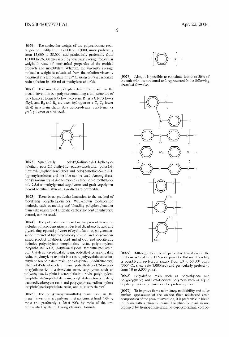
[0071] The modi?ed polyphenylene resin used in the present invention is a polymer containing a unit structure of the chemical formula beloW (Wherein, R1 is a C1-C3 loWer alkyl, and R2 and R3 are each hydrogen or a C1-C3 loWer alkyl) in a main chain. Any homopolymer, copolymer or graft polymer can be used.
[0072] Speci?cally, poly(2,6-dimethyl-1,4-phenyle ne)ether, poly(2,6-diethyl-1,4-pheneylene)ether, poly(2,6 dipropyl-1,4-phenylene)ether and poly(2-methyl-6-ethyl-1, 4-phenylene)ether and the like can be used. Among these, poly(2,6-dimethyl-1,4-pheneylene) ether, 2,6-dimethylphe nol, 2,3,6-trimethylphenol copolymer and graft copolymer thereof to Which styrene is grafted are preferable.
[0073] There is no particular limitation to the method of modifying polyphenylenether. Well-known modi?cation methods, such as melting and blending polyphenylenether resin With unsaturated aliphatic carboXylic acid or anhydride thereof, can be used.
[0074] The polyester resin used in the present invention includes polycondensation products of dicarboXylic acid and glycol, ring-opened polymer of cyclic lactone, polyconden sation product of hydroXycarboXylic acid, and polyconden sation product of dibasic acid and glycol, and speci?cally includes polyethylene terephthalate resin, polypropylene terephthalate resin, polytrimethylene terephthalate resin, poly butylene terephthalate resin, polyethylene naphthalate resin, polybutylene naphthalate resin, polycycloheXanedim ethylene terephthalate resin, polyethylene-1,2-bis(phenoXy) ethane-4,4‘-dicarboXylate resin, polyethylene-1,2-bis(phe noXy)ethane-4,4‘-dicarboXylate resin, copolymer such as polyethylene isophthalate/terephthalate resin, polybutylene terephthalate/isophthalate resin, polybutylene terephthalate/ decanedicarboXyate resin and polycycloheXanedimethylene terephthalate/isophthalate resin, and miXtures thereof.
[0075] The poly(phenylenesul?de) resin used in the present invention is a polymer that contains at least 70% by mole and preferably at least 90% by mole of the unit represented by the folloWing chemical formula.
Apr. 22, 2004
+o+ [0076] Also, it is possible to constitute less than 30% of the unit With the structural unit represented in the folloWing chemical formulas.
S
S ,
?gs ’ O
[0077] Although there is no particular limitation on the melt viscosity of these PPS resin provided that melt blending is possible, it preferably ranges from 10 to 50,000 poise (300° C., shear rate 1,000/sec) and particularly preferably from 10 to 5,000 poise.
[0078] Polyole?ne resin such as polyethylene and polypropylene; and liquid crystal polymers such as liquid crystal polyester polymer can be preferably used.
[0079] To improve ?ame retardancy, moldability and outer surface appearance of the carbon ?ber reinforced resin composition of the present invention, it is preferable to blend the resin With a phenolic resin. The phenolic resin is one prepared by homopolymerZing or copolymeriZing compo
US 2004/0077771 A1
nents containing at least phenolic hydroxyl group. For example, phenolic resin (phenolnovolak, cresolnovolak, octylphenol, phenylphenol, naphtholnovolak, phenolaralkyl, naphtholaralkyl, phenolresol and the like) or modi?ed phe nolic resin (alkylbenZene modi?ed (especially, xylene modi ?ed) phenolic resin, casheW modi?ed phenolic resin, terpene modi?ed phenolic resin and the like) can be included. In vieW of ?ame retardancy, the preferred phenolic polymer includes phenolnovolak resin, phenolaralkyl resin and the like. When large amounts of component (B) are used, hoWever, it is preferable to combine the following phenolic resin in vieW of moldability or outer surface appearance.
[0080] The phenolic resin is prepared by condensation reaction of a phenol or a substitute derivative thereof (pre cursor a) and a hydrocarbon having tWo double bonds (precursor b). A phenol substituted With 1 to 3 groups selected from alkyl, halogen and hydroxyl at the benZene nucleus is preferably used for precursor a. Speci?cally, cresol, xylenol, ethylphenol, butylphenol, t-butylphenol, nonylphenol, 3,4,5-trimethylphenol, chlorophenol, bro mophenol, chlorocresol, hydroquinone, resorcinol, orcinol and the like can be used. One or at least tWo of these can be combined. Particularly, phenol and cresol are preferably used.
[0081] Aliphatic hydrocarbons such as butadiene, iso prene, pentadiene, and hexadiene; alicyclic hydrocarbons such as cyclohexadiene, vinylcyclohexene, cycloheptadiene, cyclooctadiene, 2,5-norbornadiene, tetrahydroindene, dicy clopentadiene, monocyclic monoterpene (e.g. dipentene, limonone, terpinolene, terpinene and phellandrene), dicyclic sesquiterpene (e.g. cadinene, selinene and caryophyllene) and the like can be used for precursor b. One or at least tWo of these can be combined. Particularly, monocyclic monot erpene and dicyclopentadiene are preferably used.
[0082] The amount of phenolic polymer to be added ranges preferably from 0.1 to 10% by Weight and more preferably from 1 to 8% by Weight based on 100% by Weight of the carbon ?ber reinforced resin composition.
[0083] The carbon ?ber resin composition of the present invention can contain additional component (D), carbon poWder to obtain higher conductivity in an easy and cheap manner. The amount of component (D) to be added ranges preferably from 0.1 to 10% by Weight and more preferably from 1 to 8% by Weight based on 100% by Weight of the resin composition in vieW of mechanical properties. The carbon poWder includes, for example, carbon black, amor phous carbon poWder, natural graphite poWder, arti?cial graphite poWder, expanded graphite poWder, pitch micro bead and the like. Among these, carbon black is preferable because it is cheap and ef?cient. For the carbon black, furnish black, acetylene black, thermal black, channel black and the like can be used, and mixtures containing at least tWo thereof can also be used. In collective vieW of supply, price and ability to provide conductivity, the furnish black is preferable, Which is cheap and effective at providing con ductivity.
[0084] The preferred carbon black to achieve the balance betWeen good conductivity and moldability has a speci?c raman spectrum, as suggested in Japanese Patent Laid-open publication No. (Hei) 11-329078. The ratio of the raman scattering intensity (12/11), with I1 being the maximum value of raman band occurring near the raman shift of 1360
Apr. 22, 2004
cm'1 and I2 being the minimum value of raman band occurring near the raman shift of 1500 cm_1, ranges pref erably from 0.4 to 0.8, more preferably from 0.50 to 0.77, and particularly preferably from 0.65 to 0.75.
[0085] The 12/11 relates to the scattering intensity of raman band after baseline correction. The baseline correc tion is to correct slope of the measured baseline after a linear approximation of the baseline of the raman spectrum in the raman shift range of 600 to 2200 cm'1 and then using the distance from the approximated line as the raman scattering intensity. [0086] If the maximum value of raman band occurring near the raman shift of 1580 cm'1 is taken as I3, the standard for the more preferred carbon black is that the intensity ratio of the raman band I1:I2:I3 ranges from 1.3 to 2.1:1:1.5 to 2.5, more preferably from 1.3 to 2.011115 to 2.2, and particularly preferably from 1.40 to 1.55:1:1.60 to 1.75.
[0087] The raman spectrum is measured by laser raman spectroscopy. The raman spectrum can be measured from the carbon black before blended to resin or the carbon black separated from the resin composition or the molded products therefrom. The former can be measured by macro raman (the diameter of laser spot is about 100 pm), and the latter can by measured by microscopic raman (the diameter of laser spot is about 5 pm).
[0088] The carbon ?ber resin composition of the present invention can contain additional component (E), ?ame retar dant to obtain high ?ame retardancy. The amount to be added ranges preferably from 0.1 to 30% by Weight and more preferably from 1 to 10% by Weight based on 100% by Weight of the resin composition in vieW of balance of mechanical properties.
[0089] For the ?ame retardant used in the present inven tion, Well-knoWn ?ame retardants such as halogen type, phosphorus type, inorganic type and the like can be used Without particular limitation. Speci?cally, halogene type ?ame retardants such as tetrabromobisphenolA(TBBA) and the derivatives thereof, decabromodiphenylether, bromo bisphenol S, tetrabromophthalic anhydride, polydibro mophenylene oxide, hexabromocyclododecane, ethylenebi stetrabromophthalimide, ethylenebisdibromonorborandicarboxylimide, pentabromo diphenyloxide, tetradecabromodiphenoxybenZene, hexabro mobenZene, brominated epoxy type ?ame retardant, bromi nated polycarbonate type ?ame retardant, brominated polyphenyleneoxide type ?ame retardant, brominated sty rene type ?ame retardant and the like; phosphorus type ?ame retardants such as red phosphorus, alkylphosphate, allylphosphate, alkylallylphosphate, condensed aromatic phosphoric ester, chlorophosphonitrile derivative, phos phoamide type ?ame retardant, vinylphosphonate, allylphosphonate, polyphosphoric acid ammonium, poly phosphoric. acid amide, melamine phosphate and the like; inorganic ?ame retardants such as magnesium hydroxide, aluminum hydroxide, barium hydroxide, Zinc hydroxide, aluminum hydroxide, Zirconium hydroxide, antimony triox ide, antimony tetraoxide, antimony pentaoxide, tin oxide, tin hydroxide, Zirconium oxide, molybdenum oxide, titanium oxide, manganese oxide, cobalt oxide, ferrous oxide, ferric oxide, cuprous oxide, cupric oxide, Zinc oxide, cadmium oxide, ammonium molybdate, Zinc borate, barium borate, calcium aluminate, clay and the like; nitrogen-containing
US 2004/0077771 A1
types such as cyanuric acid, isocyanuric acid, melamine, melamine cyanurate, guanidine nitrate and the like; ?ame retardant aids such as silicone type polymer (polyorganosi loxane and the like), polytetra?uoroethylene (PTFE) and the like can be used. The phosphorus type ?ame retardant, particularly red phosphorus, is preferable in vieW of ?ame retardancy (content of phosphorus) and environmental com patibility. [0090] Because the red phosphorus, used in the red phos phorus type ?ame retardant, is unstable by itself, and has a tendency to react With Water sloWly or to be dissolved in Water sloWly, it is preferable to treat the red phosphorous to prevent these problems. The treatment of the red phosphorus includes making red phosphorous particulate Without destroying their surface so that they do not have high reactivity With Water or oxygen on their surface as suggested in Us. Pat. No.5,292,494. The treatment may also include catalytically inhibiting oxidation of the red phosphorus by adding small amounts of aluminum hydroxide or magne sium hydroxide to the red phosphorus; inhibiting contact of the red phosphorous With Water by coating the red phos phorus With paraf?n or Wax; stabiliZing the red phosphorous by mixing it With e-carpolactam or trioxane; stabiliZing the red phosphorous by coating the red phosphorus With ther mosetting resin such as phenolic type resin, melamine type resin, epoxy type resin, unsaturated polyester type resin and the like; stabiliZing the red phosphorous by treating the red phosphorus With the solutions of metal salt, such as cupper, nickel, silver, iron, aluminum and titanium and depositing metal phosphorus compound on the surface of the red phosphorus; coating the red phosphorus With aluminum hydroxide, magnesium hydroxide, titanium hydroxide, Zinc hydroxide and the like; stabiliZing the red phosphorous by electroless plating the surface of red phosphorus With iron, cobalt, nickel, manganese, tin and the like; and combining the above treatments. Among these, it is preferable to make red phosphorous particulate Without destroying their sur face, to stabiliZe the red phosphorous by coating the red phosphorus With thermosetting resins such as phenolic type resin, melamine type resin, epoxy type resin, unsaturated polyester type resin and the like, or to combine these tWo treatments. The most preferred treatment method is to make red phosphorous particulates Without destroying their sur face so that they do not have high reactivity With Water or oxygen on their surface, folloWed by catalytically inhibiting oxidation of the red phosphorus by adding small amounts of aluminum hydroxide or magnesium hydroxide to the red phosphorus, and, subsequently, to coat the red phosphorous With phenolic thermosetting resin or epoxy thermosetting resm.
[0091] For ?ame retardancy, mechanical properties and inhibition of chemical and physical deterioration of the recycled red phosphorus due to crash of the red phospho rous, the average particle diameter of the red phosphorus before blended to the resin composition ranges preferably from 0.01 to 35 pm and particularly preferably from 0.1 to 30 pm.
[0092] The average diameter of the red phosphorus can be measured With a general laser diffraction particle siZe dis tribution measurement instrument. There are tWo types of particle siZe distribution measurement instruments, a Wet method and dry method, and either type can be used. In the Wet method, Water can be used as a dispersion solvent for the
Apr. 22, 2004
red phosphorus. In this case, the surface of the red phos phorus can be treated With an alcohol or a neutral detergent. Furthermore, phosphoric acid salt such as sodium hexam etaphosphate and sodium pyrophosphate can be used as a dispersant. [0093] For ?ame retardancy, mechanical properties, and recycling of the red phosphorus, the amounts of red phos phorous With a diameter not less than 75 pm is preferably not more than 10% by Weight, more preferably not more than 8% by Weight, and particularly preferably not more than 5% by Weight. The closer to 0% by Weight the more preferable, though there is no limitation to the loWer limit.
[0094] The content of the red phosphorus With diameter not less than 75 pm can be measured by ?ltering With mesh of 75 pm. The content of the red phosphorus With diameter not less than 75 pm can be calculated from A/100><100 (%), Wherein A (g) is the ?ltered amount of the red phosphorous When 100 g of red phosphorous is ?ltered With the mesh of 75 pm.
[0095] For moisture resistance, mechanical properties, conductivity and recycling of the molded products, conduc tivity of the red phosphorous extracted from hot Water is measured. The values are measured by conductivity meter [YokokaWa Electric Corporation, personal SC meter] from 250 ml of diluted Water. The dilution is prepared by the folloWing process: 100 ml of pure Water is added to 5 g of the red phosphorus. The solution is extracted, for example in an autoclave, at a temperature of 121° C. for 100 hours. Then, the red phosphorus is ?ltered from the solution, and the ?ltrate is diluted to 250 ml. Conductivity ranges pref erably from 0.1 to 1000 pS/cm, more preferably from 0.1 to 800 pS/cm, and particularly preferably from 0.1 to 500 pS/cm.
[0096] The folloWing additives can be added to the carbon ?ber reinforced resin composition of the present invention according to the need in demand: ?ller (mica, talc, kaoline, sericite, bentonite, xonotlite, sepiolite, smectite, montmoril lonite, Wollastonite, silica, calcium carbonate, glass bead, glass ?ake, glass micro balloon, clay, molybdenum disul phide, titanium oxide, Zinc oxide, antimony oxide, calcium polyphosphate, graphite, barium sulfate, magnesium sulfate, Zinc borate, calcium borate, aluminum borate Whisker, potassium titanate Whisker, polymer and the like), conduc tivity providing agent (metallic type, metal oxide type and the like), ?ame retardant, ?ame retardant aid, pigment, dye, lubricant, releasing agent, compatibiliZer, dispersant, crys talliZing agent (mica, talc, kaoline and the like), plasticiZer (phosphate ester and the like), thermal stabiliZer, antioxi dant, anticoloring agent, UV absorbent, ?oWability modi?er, foaming agent, antibacterial agent, dust controlling agent, deodorant, sliding modi?er, antistatic agent (polyetherest eramide and the like) and the like. TWo or more additives can be combined.
[0097] The ?ller can be sWelled by a sWelling agent or can be organi?ed by an organi?cation agent. The sWelling agent and organi?cation agent are not particularly limited, if they can sWell or organify a ?ller by ion exchange and the like, and include e-caprolactam, 12-aminododecanoic acid, 12-aminolauric acid, alkyl ammonium salt (dimethyldialky lammonium and the like). Particularly, it is preferred that polyamide resin, polypropylene resin, polyacetal resin, sty renic resin, acrylic resin and the like are blended With the
US 2004/0077771 A1
swelled or organi?ed ?ller (preferably, montmorillonite, mica, saponite, hectorite sepiolite, clay), because the nano order distribution of the ?ller is possible, thereby, the desired property can be obtained With small amounts.
[0098] The carbon ?ber reinforced resin composition or molding compounds of the present invention can be molded With a molding process, such as injection molding (injection compression molding, gas assisted injection molding, insert molding and the like), bloW molding, rotary molding, extru sion molding, press molding, transfer molding (RTM mold ing, RIM molding, SCRIMP molding and the like), ?lament Winding molding, autoclave molding, hand lay-up molding and the like. The most preferred molding process among these is the injection molding With high productivity.
[0099] As a form of the molding compounds used in above molding process, pellet, stampable sheet, prepreg, SMC, BMC and the like can be used. The most preferred form of the molding compounds is a pellet, Which is used in the injection molding.
[0100] The pellet generally de?nes a material obtained from the folloWing process: melt blending the desired amount of the resin With ?ller or chopped ?ber or continuous ?lament, and then extruding and palletiZing. The melt blend ing method is not particularly limited, and any machine, Which can give mechanical shear to the component (C) under the molten state, such as single extruder, tWin extruder or kneader, can be used.
[0101] To obtain good conductivity or mechanical prop erties required for member of electronic devices, it is pre ferred that the pellet should be a molding compound having a pillar shape. This pillared molding compound (long ?ber pellet) enables easy manufacture for aspect ratios larger than that of the conventional knoWn pellet. The pillared molding compound is also advantageous in vieW of conductivity and mechanical properties of the molded products.
[0102] Component (B) is arranged almost parallel to the axial direction (length direction of the molding compounds), and the length of component (B) is substantially equal to the length of the molding compounds. When component (B) is curved, bent or tWisted, the length of component (B) can be slightly longer than the length of the molding compounds. The phrase “substantially equal to” includes these cases. If almost equal shape of cross-section of the molding com pound is maintained in the axial direction, it can be regarded that the length of component (B) is substantially equal to the length of molding compound.
[0103] For handling ease, it is preferred that the pillared molding compounds have a complex structure, Wherein structure B that has as main component component (B) and structure A that has as main component component (C) are in contact With each other at one or more points. It is preferred to maintain the complex structure Without sepa rating structure A and B When handling the molding com pounds. In this complex structure, a gap can exist betWeen the boundaries of structure A and structure B or in the structure B. HoWever, a complex structure With a face of structure A and a face of structure B in contact With each other is preferred in vieW of the above considerations. A sheath-core structure is particularly preferred to prevent breakup or separation of the bundle of the reinforcing ?ber of component (B), Wherein structure B is core structure and
Apr. 22, 2004
structure A is sheath structure so that structure A coats around structure B. If the minimum thickness of the coating layer of structure A of the sheath structure is equal to or above 0.1 mm, the above purpose can be suf?ciently achieved.
[0104] Component (A) can be contained in any of said structures A and/or B. HoWever, in vieW of preferred embodiment of the pillared molding compounds, it is pref erable that component (A) is contained in structure A.
[0105] In vieW of the optimum balance betWeen mechani cal properties and moldability, the length of the pillared molding compounds ranges preferably from 1 to 50 mm, more preferably from 2 to 20 mm, and particularly prefer ably from 3 to 12 mm. It is preferable to control the thickness of the pillared molding compounds to be from 1 to 10 mm for good handling, although not particularly limited thereto.
[0106] It is preferable that the above-mentioned phenolic polymer is contained into structural element (C) to improve the moldability of the pillared molding compounds. Particu larly, if some or all of the phenolic polymers are impreg nated into structural element (B), the dispersity of structural element (B) is improved. It is also preferable for moldabilty and outer surface appearance. The outer surface appearance de?nes avoidance of various defects in the surface that results from insuf?cient dispersion of the reinforcing ?bers, Wherein the defects include, for instance the phenomena of ?ber bundles rising up to the surface or some portions of the molded products expanding.
[0107] Apreferred embodiment of a process for preparing the pillared molding compounds is illustrated beloW.
[0108] The pillared molding compounds are prepared by at least the folloWing ?rst and second processes.
[0109] The ?rst process includes a strandi?cation process comprising melting component A containing at least com ponents (A) and/or (C), and passing at least continuous component (B) therethrough to obtain continuous strand. The method for melting component (A) is not particularly limited and can use any machines, Which can provide mechanical shear under the molten state and transfer the molten resin, such as a single extruder, tWin extruder and the like. It is preferable to install a vent to remove volatile components of loW molecular Weight or Water vapor gen erated in this melt blending. It is also preferable to install a plurality of hoppers to add components during the melt blending. [0110] Other components or additives can be blended by melting them simultaneously With or separately from com ponent A and then passing at least continuous (B) there through; or by impregnating them into continuous compo nent (B) simultaneously With or separately from phenolic resin of component
[0111] The second process includes a cutting process for obtaining the pillared molding compounds by cooling and cutting the continuous strand. The continuous strand is cut to have such length as described above.
[0112] The especially preferred method for preparing the pillared molding compounds has the folloWing preliminary process before the ?rst process. The phenolic resin of component (C) is melted and impregnated into component
US 2004/0077771 A1
(B) in the preliminary process. From this process, the composite of phenolic resin of component (C) and compo nent (B) is obtained. This composite is passed through the molten component A in the ?rst process to give a continuous strand, Which is cooled and cut in the second process.
[0113] By going through this preliminary process and forming the composite of components (B) and (C), the time period for the strandi?cation of the ?rst process can be shortened, and the productivity of the molding compounds becomes good. Therefore, the preliminary process is pref erable as a process for preparing the molding compounds of the present invention.
[0114] The above pellet or long ?ber pellet of the present invention can be used solely or combined With one another as molding compounds. They can be mixed With other molding compounds such as other thermoplastic resin, addi tive and master pellet. They also can be mixed With scraps of molded products or various recycled resins.
[0115] Because the molded products of the present inven tion has good conductivity, the volume resistivity of the molded products is preferably equal to or less than 50 Q-cm. If the volume resistivity of the molded products is greater than 50 Q-cm, they may sometimes not be used for appli cation as electromagnetic shielding material. The volume resistivity of the molded products prepared from the mold ing compounds of the present invention is preferably equal to or less than 30 Qcm, more preferably equal to or less than 10 Q-cm, particularly preferably equal to or less than 1 Q-cm, and most preferably equal to or less than 0.4 Q-cm.
[0116] It is preferable that the molded products of the present invention have high ?ame retardancy as Well as good conductivity When the molded products are mixed With a ?ame retardant. It is preferable that the ?ame retardancy is equal to or better than V-O under the standard of UL-94 When a specimen With a thickness of not more than 1.6 mm (1/16 inch) is tested. It is more preferable that the ?ame retardancy is equal to or better than V-O under the standard of UL-94 When a specimen With a thickness of not more than 0.8 mm
(1/32 inch) is tested.
[0117] The ?ame retardancy of V-O means ?ame retar dancy satisfying the condition of V-O de?ned in the standard of UL-94 (combustion test in US. designed by UnderWriters Laboratories Inc.) With combustion time, occurrence of combustion, occurrence of drip of burned resin, combusti bility of the drip and the like. A?ame retardancy better than V-O means ?ame retardancy shoWing shorter combustion time than the value de?ned in V-O condition or satisfying the condition of V-O When a specimen of Which thickness is thinner than that of the specimen of V-O is tested.
[0118] It is preferable that the molded products of the present invention have improved mechanical properties, particularly high modulus to protect internal electric circuit or internal member because they are used in member of a thin electronic devices. The ?exural modulus of the molded products is preferably equal to or greater than 8 GPa, more preferably equal to or greater than 10 GPa, and particularly preferably equal to or greater than 12 GPa When a specimen With the thickness of 6.4 mm and the moisture content of equal to or less than 0.05% is tested under ASTM D790.
[0119] The molded products of the present invention are expected to be exposed to harsh conditions When they are
Apr. 22, 2004
used in member of portable electronic devices. Especially, When polyamide resin is used for the molded products, the products have an intrinsic problem of decrease of modulus by moisture absorption. Therefore, for practical mechanical properties, the ?exural modulus of the molded products is preferably equal to or greater than 6 GPa, more preferably equal to or greater than 8 GPa, and particularly preferably equal to or greater than 10 GPa When a specimen of 6.4 mm thickness hygroscopically treated in constant temperature and constant-moistened bath of 65° C. and 95% RH for 100 hours is tested under ASTM D790. Wherein, the moisture content depends on the amount of polyamide in the resin composition and generally ranges from 0.5 to 4% by Weight. When the specimen is hygroscopically treated, the speci mens must not contact With other specimens in the constant temperature and constant-moistened bath. After the hygro scopic treatment, the specimen is kept at room temperature for at least 10 hours so that the moisture content remains. After that, the specimen is used to measure the ?exural modulus.
[0120] The molded products of the present invention can be used in member of electronic devices, of?ce automation devices, precision devices, and automobiles requiring good conductivity and mechanical properties (particularly, modu lus), Wherein the member is, for instance, a casing, a cover and a tray. Particularly, the molded products of the present invention can be used for casings of portable electronic devices requiring especially good conductivity (electromag netic shielding property) and high strength (light Weight). More speci?cally, the molded products of the present inven tion can be used for casings of large scale display, notebook computers, mobile telephones, PHS, PDA (personal data assistant such as electronic pocketbook), video cameras, video cameras, digital still cameras, portable radio cassette players, inverters and the like.
[0121] Because the molded products of the present inven tion have good conductivity, electric charge/discharge resis tance can be provided to the products With the addition of small amounts of carbon ?ber. Therefore, they are useful for devices or parts requiring such properties, for example, IC trays, baskets for silicon Wafer transfer and parts of enter tainment machines having electric circuits such as slot machines (Chassis) and the like.
[0122] It is advantageous for the ?ber of component (B) contained in the molded products used in the above-men tioned application to be long to achieve good conductivity and mechanical properties. The number average ?ber length is preferably at least 200 pm, more preferably at least 250 pm, and particularly preferably at least 300 pm. The number average ?ber length is calculated by measuring the length of at least 400 components (B) extracted from the molded products, With an optical microscope or scanning electronic microscope to a 1 pm degree and averaging the measure ments. Component (B) can be extracted, for example, by extracting a portion of the molded product, dissolving it in a solvent that dissolves component (C) but not (B) for a period, and separating (B) With a knoWn process such as ?ltering after component (C) is suf?ciently dissolved. The extracted portion should not be taken from and around Weld lines, gates, ribs, hinges and edges of the molded products.
[0123] It is preferable that the molded products have good electromagnetic shielding property. The electromagnetic
US 2004/0077771 A1
shielding property at the frequency of 1 GHZ, determined With KEC method, is preferably at least 30 dB, more preferably at least 33 dB, and particularly preferably at least 35 dB.
[0124] The KEC method measures the degree of attenu ation of the electronic Wave With a spectrum analyZer after a specimen is inserted into a shield box that is symmetrically divided up and doWn or right and left according to the guidelines of KEC Corporation. The specimen can be taken from a plate of appropriate area extracted from a portion of the molded product having electromagnetic shielding prop erty or from molded product made from a plate of appro priate area obtained from the thermoplastic resin composi tion or model product under the same molding conditions as the molded products having electromagnetic shielding prop erty.
EXAMPLES
[0125] The present invention is more speci?cally illus trated by the folloWing examples. Hereinafter, “%” in the mixing (blending) ratios in examples and comparative examples means % by Weight, unless otherWise speci?ed.
[0126] The test items and procedures for the molded products composed of molding compounds or carbon ?ber reinforced resin composition of the present invention are described beloW:
[0127] [Test procedures to determine the characteristics of the carbon ?ber reinforced resin composition]
[0128] (1) Volume Resistivity [0129] A specimen of Width 12.7 mm><length 65 mm><thickness 2 mm Was injection molded so that a gate is positioned at the edge of the Width direction. A conductive paste (manufactured by Fujikurakasei Co., Ltd., Dotite) Was applied on the Width><thickness surface of the molded speci men. After the conductive paste Was suf?ciently dried, the specimen Was measured under absolutely dried condition (moisture content of not more than 0.05%). In measurement, the surface of the Width><thickness Was pressed to electrodes. The electrical resistance betWeen the electrodes Was mea sured With a digital multimeter (manufactured by Advantest Corporation, R6581). The volume resistivity (unitzQcm) Was calculated by subtracting the contact resistance of the measuring devices, jig and the like from the above electrical resistance, multiplying With the applied area of the conduc tive paste, and dividing With the length of the specimen. In this measurement, 10 samples Were measured and averaged.
[0130] (2) Flexural Modulus
[0131] The ?exural modulus (unit: GPa) Was evaluated by the ?exure test based on ASTM D790 (L/D=16, Wherein L is distance betWeen spans and D is thickness). The plate thickness of the specimen Was 6.4 mm (% inch). The ?exural modulus (d) Was measured at the moisture content of not more than 0.05%. In this measurement, 5 samples Were measured and averaged.
[0132] Also, the specimen Was hygroscopically treated by standing in a constant temperature and constant-moistened bath at 65° C. and 95% RH for 100 hours. The specimen Was kept so that the hygroscopic state Was maintained. The ?exural modulus (W) Was measured according to the above procedure.
Apr. 22, 2004
[0133] (3) IZod Impact Strength [0134] The notched IZod impact strength of the molded products (unit: J/m) Was evaluated based on ASTM D256. The thickness of the test specimen Was 3.2 mm (Vs inch). The IZod Impact strength test Was performed at the moisture content of not more than 0.05%. In this measurement, 10 samples Were measured and averaged.
[0135] (4) Flame Retardancy [0136] The ?ame retardancy Was evaluated based on UL-94. The thickness of the tested specimen Was 0.8 mm (1/32 inch). The specimen Was obtained from injection mold ing With the ?lm gate extended to a total length of the longer side direction of the specimen.
[0137] [Test procedures to determine characteristics of molded products having electromagnetic shielding property]
[0138] First, model casing (3) for electronic devices rep resented in FIG. 7 Was molded and tested. The model casing for electronic devices has an upper surface (4) of length (L) 190 mm><Width 155 mm and height of 12 mm, With at least 70% of the thickness of the upper surface being about 1.0 mm. Because the specimen Was molded With 8 gate points in the injection molding, the Weld line (5) represented in FIG. 7 Was obtained. Among them, the Weld line positioned at the center of the upper surface had the maximum height.
[0139] (5) Moldability [0140] Moldability (unitzMPa) Was evaluated With the injection pressure measured When the model casing for electronic devices Was injection molded. The loWer the injection pressure, the better the moldabilty.
[0141] (6) Number Average Fiber Length
[0142] About 1 g Was cut from the upper surface of the model casing for electronic devices and dissolved in 100 cc of formic acid. The solution Was left alone for 12 hours. After component (C) PA Was absolutely dissolved, it Was ?ltered through ?lter paper. The ?ltered residue Was observed With a microscope. The ?ber length of 400 com ponents (B), Which Was randomly extracted, Was measured to calculate the number average ?ber length.
[0143] (7) Electromagnetic Shielding Property [0144] Electromagnetic shielding property Was tested With the KEC method (unit:db). A portion of the center of the upper surface of the model casing (3) for electronic devices Was cut to prepare a specimen of 120 mm><120 mm. In the test, the specimen Was made to absolutely dried state (mois ture content of not more than 0.05%), four sides of the specimen Were coated With the conductive paste (manufac tured by Fujikurakasei Co., Ltd., Dotite) and suf?ciently dried. The electromagnetic shielding property Was measured at the frequency of 1 GHZ With a spectrum analyZer. The more the shielded electromagnetic Waves, the better the electromagnetic shielding property.
[0145] (8) Outer Surface Appearance
[0146] The maximum height (Ry) in the measurement range (6) of the outer surface appearance of the model casing for electronic devices, represented in FIG. 7, Was evaluated based on JIS B0601 (unit: pm). The outer surface appear ance Was evaluated at a region that did not contain the trace
US 2004/0077771 A1
of a gate and rib and Was perpendicular to the center Weld line of the upper surface of the model casing for electronic devices at one point under the condition of test length of 3.00 mm and cut-off value of 0.25 mm. Surf Tester 301 manu factured by Mitutoyo Corporation Was used as the test device. The lesser the Ry value, the better the outer surface appearance.
[0147] Finally, the balance of the conductivity, the mechanical properties, the moldability and the outer surface appearance in the above test items Was synthetically assessed With a category of 5 states of 000: excellent, 00: very good, O: good, A: not good and X: bad.
[0148] Each component used in the examples and the comparative examples of the present invention are as fol loWs:
[0149] Component (A) [0150] NT: Vapor groWn multi-layer nanotube manufac tured by Hyperion Catalysis International. [average diameter of single ?ber=about 15 nm]
[0151] Component (B) [0152] CF1: Chopped ?ber 48 (X8) manufactured by Zoltek Companies, Inc. [average diameter of single ?ber=7 mm] [0153] CF2: PAN type carbon ?ber T700SC-12K manu factured by Toray Industries, Inc. [average diameter of single ?ber=7 pm]
[0154] Component (C) [0155] PC: Polycarbonate resin LEXAN 121R manufac tured by Japan GE Plastics.
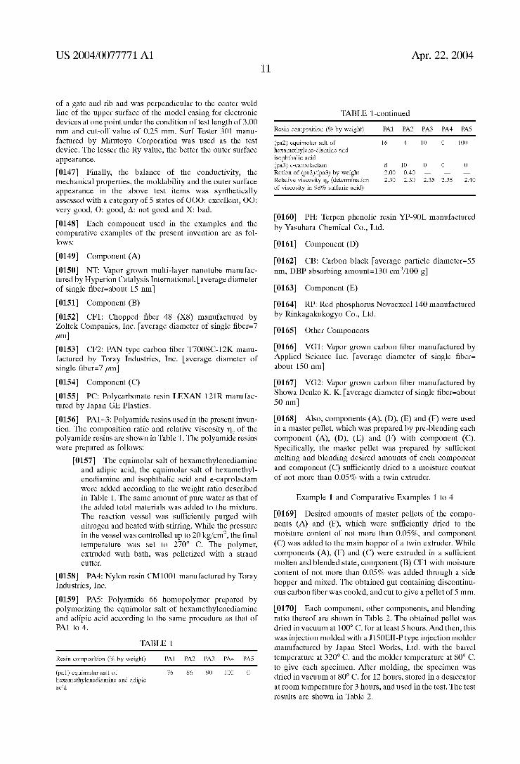
[0156] PA1~3: Polyamide resins used in the present inven tion. The composition ratio and relative viscosity m of the polyamide resins are shoWn in Table 1. The polyamide resins Were prepared as folloWs:
[0157] The equimolar salt of hexamethylenediamine and adipic acid, the equimolar salt of hexamethyl enediamine and isophthalic acid and e-caprolactam Were added according to the Weight ratio described in Table 1. The same amount of pure Water as that of the added total materials Was added to the mixture. The reaction vessel Was sufficiently purged With nitrogen and heated With stirring. While the pressure in the vessel Was controlled up to 20 kg/cm2, the ?nal temperature Was set to 270° C. The polymer, extruded With bath, Was pelletiZed With a strand cutter.
[0158] PA4: Nylon resin CM1001 manufactured by Toray Industries, Inc.
[0159] PAS: Polyamide 66 homopolymer prepared by polymeriZing the equimolar salt of hexamethylenediamine and adipic acid according to the same procedure as that of PA1 to 4.
TABLE 1
Resin composition (% by Weight) PA1 PA2 PA3 PA4 PAS
(pa1) equirnolar salt of 76 86 90 100 0 hexamethylenediamine and adipic acid
Apr. 22, 2004
TABLE 1-continued
Resin composition (% by Weight) PA1 PA2 PA3 PA4 PAS
(pa2) equirnolar salt of 16 4 10 0 100 hexamethylene-diamine and isophthalic acid (pa3) e-caprolactam 8 10 0 0 0 Ration of (pa2)/(pa3) by Weight 2.00 0.40 — — —
Relative viscosity nI (determination 2.30 2.30 2.35 2.35 2.40 of viscosity in 98% sulfuric acid)
[0160] PH: Terpen phenolic resin YP-90L manufactured by Yasuhara Chemical Co., Ltd.
[0161] Component (D)
[0162] CB: Carbon black [average particle diameter=55 nm, DBP absorbing amount=130 cm3/100 g]
[0163] Component
[0164] RP: Red phosphorus Novaexcel 140 manufactured by Rinkagakukogyo Co., Ltd.
[0165] Other Components
[0166] VG1: Vapor groWn carbon ?ber manufactured by Applied Science Inc. [average diameter of single ?ber= about 150 nm]
[0167] VG2: Vapor groWn carbon ?ber manufactured by ShoWa Denko K. K. [average diameter of single ?ber=about 50 nm]
[0168] Also, components (A), (D), and Were used in a master pellet, Which Was prepared by pre-blending each
component (A), (D), and With component Speci?cally, the master pellet Was prepared by suf?cient
melting and blending desired amounts of each component and component (C) sufficiently dried to a moisture content of not more than 0.05% With a tWin extruder.
Example 1 and Comparative Examples 1 to 4
[0169] Desired amounts of master pellets of the compo nents (A) and (E), which Were suf?ciently dried to the moisture content of not more than 0.05%, and component (C) Was added to the main hopper of a tWin extruder. While components (A), and (C) Were extruded in a suf?cient molten and blended state, component (B) CF1 With moisture content of not more than 0.05% Was added through a side hopper and mixed. The obtained gut containing discontinu ous carbon ?ber Was cooled, and cut to give a pellet of 5 mm.
[0170] Each component, other components, and blending ratio thereof are shoWn in Table 2. The obtained pellet Was dried in vacuum at 100° C. for at least 5 hours. And then, this Was injection molded With a J150EII-P type injection molder manufactured by Japan Steel Works, Ltd. With the barrel temperature at 320° C. and the molder temperature at 80° C. to give each specimen. After molding, the specimen Was dried in vacuum at 80° C. for 12 hours, stored in a desiccator at room temperature for 3 hours, and used in the test. The test results are shoWn in Table 2.
US 2004/0077771 A1
TABLE 2
Resin Example Comparative Example
composition (% by weight) 1 1 2 3 4
Component (A) NT 0.5 — 3.0 — —
Component (B) CF1 30.0 30.0 30.0 30.0 30.0 Component (C) PC 79.5 80.0 77.0 79.5 79.5 Other components
VG1 — — 0.5 —
VG2 — — — 0.5
Characteristics of the molded products
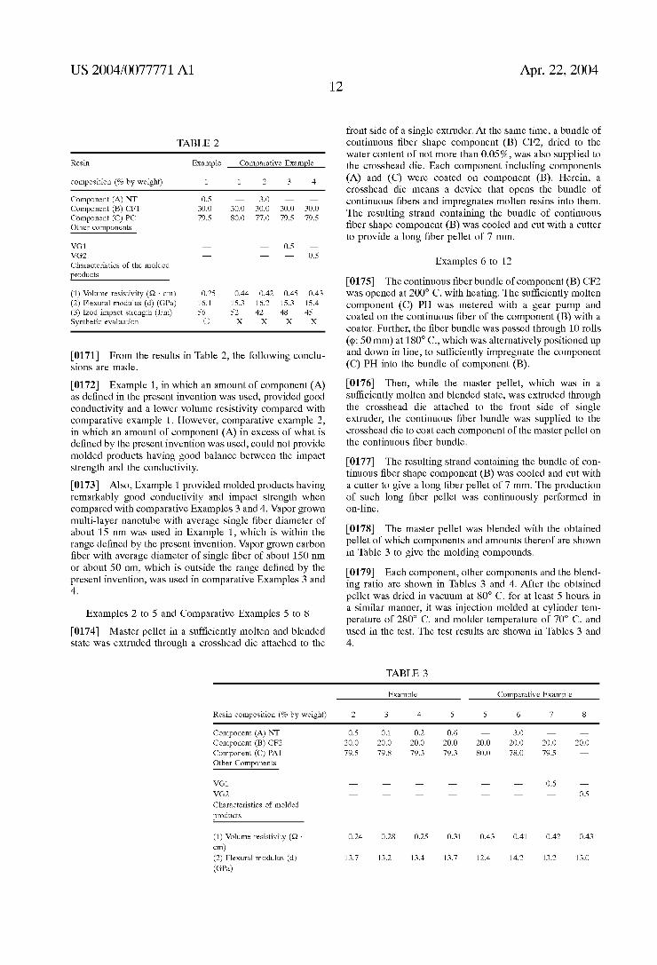
(1) Volume resistivity (Q - cm) 0.25 0.44 0.42 0.45 0.43 (2) Flexural modulus (d) (GPa) 16.1 15.3 16.2 15.3 15.4 (3) Izod impact strength (J/m) 56 52 42 48 45 Synthetic evaluation Q X X X X
[0171] From the results in Table 2, the following conclu sions are made.
[0172] Example 1, in which an amount of component (A) as de?ned in the present invention was used, provided good conductivity and a lower volume resistivity compared with comparative example 1. However, comparative example 2, in which an amount of component (A) in excess of what is de?ned by the present invention was used, could not provide molded products having good balance between the impact strength and the conductivity.
[0173] Also, Example 1 provided molded products having remarkably good conductivity and impact strength when compared with comparative Examples 3 and 4. Vapor grown multi-layer nanotube with average single ?ber diameter of about 15 nm was used in Example 1, which is within the range de?ned by the present invention. Vapor grown carbon ?ber with average diameter of single ?ber of about 150 nm or about 50 nm, which is outside the range de?ned by the present invention, was used in comparative Examples 3 and 4.
Examples 2 to 5 and Comparative Examples 5 to 8
[0174] Master pellet in a suf?ciently molten and blended state was extruded through a crosshead die attached to the
Apr. 22, 2004
front side of a single extruder. At the same time, a bundle of continuous ?ber shape component (B) CF2, dried to the water content of not more than 0.05%, was also supplied to the crosshead die. Each component including components (A) and (C) were coated on component Herein, a crosshead die means a device that opens the bundle of continuous ?bers and impregnates molten resins into them. The resulting strand containing the bundle of continuous ?ber shape component (B) was cooled and cut with a cutter to provide a long ?ber pellet of 7 mm.
Examples 6 to 12
[0175] The continuous ?ber bundle of component (B) CF2 was opened at 200° C. with heating. The suf?ciently molten component (C) PH was metered with a gear pump and coated on the continuous ?ber of the component (B) with a coater. Further, the ?ber bundle was passed through 10 rolls (4); 50 mm) at 180° C., which was alternatively positioned up and down in line, to suf?ciently impregnate the component (C) PH into the bundle of component
[0176] Then, while the master pellet, which was in a suf?ciently molten and blended state, was extruded through the crosshead die attached to the front side of single extruder, the continuous ?ber bundle was supplied to the crosshead die to coat each component of the master pellet on the continuous ?ber bundle.
[0177] The resulting strand containing the bundle of con tinuous ?ber shape component (B) was cooled and cut with a cutter to give a long ?ber pellet of 7 mm. The production of such long ?ber pellet was continuously performed in on-line.
[0178] The master pellet was blended with the obtained pellet of which components and amounts thereof are shown in Table 3 to give the molding compounds.
[0179] Each component, other components and the blend ing ratio are shown in Tables 3 and 4. After the obtained pellet was dried in vacuum at 80° C. for at least 5 hours in a similar manner, it was injection molded at cylinder tem perature of 280° C. and molder temperature of 70° C. and used in the test. The test results are shown in Tables 3 and 4.
TABLE 3
Example Comparative Example
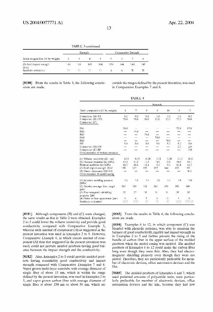
Resin composition (% by weight) 2 3 4 5 5 6 7 8
Component (A) NT 0.5 0.1 0.2 0.6 — 3 0 —
Component (B) CF2 Component (C) PA1 Other Components
VG1
Characteristics of molded
products
(1) Volume resistivity (Q -
cm) (2) Flexural modulus (d) (GPa)
20.0 20.0 20.0 20.0 20.0 20.0 20.0 20.0 79.5 79.8 79.3 79.3 80.0 78.0 79.5 —
0.24 0.28 0.25 0.31 0.43 0.41 0.42 0.43
13.7 13.2 13.4 13.7 12.4 14.2 13.2 13.0
US 2004/0077771 A1 Apr. 22, 2004 13
TABLE 3-continued
F amnle Comparative F amnle
Resin composition (% by Weight) 2 3 4 5 5 6 7 s
(3) Izod impact strength 166 161 165 164 159 144 146 145
gyrrliltlletic evaluation 0 O O O A A X X
[0180] From the results in Table 3, the following conclu sions are made.
outside the ranges de?ned by the present invention, Was used in Comparative Examples 7 and 8.
TABLE 4
F amnle
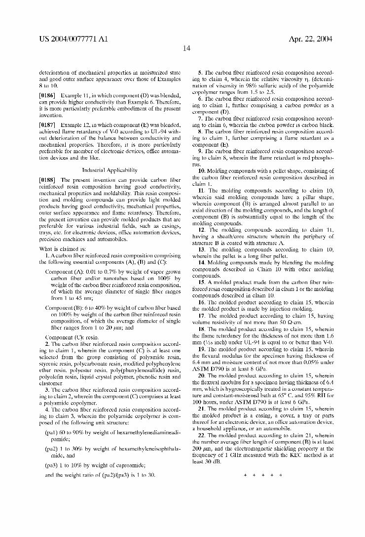
Resin composition (% by Weight) 6 7 8 9 10 11 12
Component (A) NT 0 2 0 2 0 2 0 2 0 2 0 2 0 2 Component (B) CF2 Component (C)
20.0 20.0 20.0 20.0 20.0 20.0 20.0
PA1 74.8 — — — — 72.8 67.8
PA2 — 74.8 — — — — —
PA3 — — 74.8 — — — —
PA4 — — — 74.8 — — —
PA5 — — 74.8 — —
PH 5 0 5 0 5 0 5.0 5 0 5 .0 5 0 Component (D) CB — — 2.0 2.0 Component RP — — — — — 5.0
Characteristics of molded products
(1) Volume resistivity (Q - cm) 0.22 0.20 0.20 0.21 0.20 0.12 0.12 (2) Flexural modulus (d) (GPa) 14.3 14.2 14.3 14.0 13.9 14.6 15.4 Flexural modulus (W) (GPa) 10.2 10.1 10.1 8.2 8.0 10.4 11.2 (3) Izod impact strength (J/m) 158 162 155 157 146 153 155 (4) Flame retardancy (UL-94) — — — — — — V-0
Characteristics of model casing
(1) Injection molding pressure 7.2 7.1 7.4 7.2 7.7 7.4 7.8 (MPa) (2) Number average ?ber length 415 420 405 360 345 395 380 (am) (3) Elecromagnetic shielding 32 32 33 31 31 35 35 property (dB) (4) Outer surface appearance (pm) 3 4 7 9 12 3 3 Synthetic evaluation Q Q Q Q Q Q Q Q Q Q Q Q
[0181] Although components (B) and (C) Were changed, the same results as that in Table 2 Were obtained. Examples 2 to 5 could loWer the volume resistivity and provide good conductivity compared With Comparative Example 5, Wherein such amount of component (A) as suggested in the present invention Was used in Examples 2 to 5. HoWever, Comparative Example 6, in Which excess amount of com ponent (A) than that suggested in the present invention Was used, could not provide molded products having good bal ance betWeen the impact strength and the conductivity.
[0182] Also, Examples 2 to 5 could provide molded prod ucts having remarkably good conductivity and impact strength compared With Comparative Examples 7 and 8. Vapor groWn multi-layer nanotube With average diameter of single ?ber of about 15 nm, Which is Within the range de?ned by the present invention, Was used in Examples 2 to 5, and vapor groWn carbon ?ber With average diameter of single ?ber at about 150 nm or about 50 nm, Which are
[0183] From the results in Table 4, the folloWing conclu sions are made.
[0184] Examples 6 to 12, in Which component (C) Was blended With phenolic polymer, Was able to maintain the balance of good conductivity, rigidity and impact strength as in Examples 2 to 5 and further prevent the rising of the bundle of carbon ?ber in the upper surface of the molded products When the model casing Was molded. The molded products of Examples 6 to 12 could make the carbon ?ber long even though they Were thin. Also, they had electro magnetic shielding property even though they Were not plated. Therefore, they are particularly preferable for mem ber of electronic devices, office automation devices and the like.
[0185] The molded products of Examples 6 and 7, Which used preferred amounts of polyamide resin, Were particu larly preferable for member of electronic devices, office automation devices and the like, because they had loW
US 2004/0077771 A1
deterioration of mechanical properties in moisturized state and good outer surface appearance over those of Examples 8 to 10.
[0186] Example 11, in Which component (D) Was blended, can provide higher conductivity than Example 6. Therefore, it is more particularly preferable embodiment of the present invention.
[0187] Example 12, in Which component Was blended, achieved ?ame retardancy of V-O according to UL-94 With out deterioration of the balance betWeen conductivity and mechanical properties. Therefore, it is more particularly preferable for member of electronic devices, of?ce automa tion devices and the like.
Industrial Applicability
[0188] The present invention can provide carbon ?ber reinforced resin composition having good conductivity, mechanical properties and moldability. This resin composi tion and molding compounds can provide light molded products having good conductivity, mechanical properties, outer surface appearance and ?ame retardancy. Therefore, the present invention can provide molded products that are preferable for various industrial ?elds, such as casings, trays, etc. for electronic devices, of?ce automation devices, precision machines and automobiles.
What is claimed is: 1. Acarbon ?ber reinforced resin composition comprising
the folloWing essential components (A), (B) and (C):
Component (A): 0.01 to 0.7% by Weight of vapor groWn carbon ?ber and/or nanotubes based on 100% by Weight of the carbon ?ber reinforced resin composition, of Which the average diameter of single ?ber ranges from 1 to 45 nm;
Component (B): 6 to 40% by Weight of carbon ?ber based on 100% by Weight of the carbon ?ber reinforced resin composition, of Which the average diameter of single ?ber ranges from 1 to 20 pm; and
Component (C): resin. 2. The carbon ?ber reinforced resin composition accord
ing to claim 1, Wherein the component (C) is at least one selected from the group consisting of polyamide resin, styrenic resin, polycarbonate resin, modi?ed polyphenylene ether resin, polyester resin, poly(phenylenesul?de) resin, polyole?n resin, liquid crystal polymer, phenolic resin and elastomer.
3. The carbon ?ber reinforced resin composition accord ing to claim 2, Wherein the component (C) comprises at least a polyamide copolymer.
4. The carbon ?ber reinforced resin composition accord ing to claim 3, Wherein the polyamide copolymer is com posed of the folloWing unit structure:
(pal) 60 to 90% by Weight of hexamethylenediamineadi pamide;
(pa2) 1 to 30% by Weight of hexamethyleneisophthala mide; and
(pa3) 1 to 10% by Weight of caproamide;
and the Weight ratio of (pa2)/(pa3) is 1 to 30.
Apr. 22, 2004
5. The carbon ?ber reinforced resin composition accord ing to claim 4, Wherein the relative viscosity m (determi nation of viscosity in 98% sulfuric acid) of the polyamide copolymer ranges from 1.5 to 2.5.
6. The carbon ?ber reinforced resin composition accord ing to claim 1, further comprising a carbon poWder as a component
7. The carbon ?ber reinforced resin composition accord ing to claim 6, Wherein the carbon poWder is carbon black.
8. The carbon ?ber reinforced resin composition accord ing to claim 1, further comprising a ?ame retardant as a component
9. The carbon ?ber reinforced resin composition accord ing to claim 8, Wherein the ?ame retardant is red phospho ms.
10. Molding compounds With a pellet shape, consisting of the carbon ?ber reinforced resin composition described in claim 1.
11. The molding compounds according to claim 10, Wherein said molding compounds have a pillar shape, Wherein component (B) is arranged almost parallel to an axial direction of the molding compounds, and the length of component (B) is substantially equal to the length of the molding compounds.
12. The molding compounds according to claim 11, having a sheath/core structure Wherein the periphery of structure B is coated With structure A.
13. The molding compounds according to claim 10, Wherein the pellet is a long ?ber pellet.
14. Molding compounds made by blending the molding compounds described in Claim 10 With other molding compounds.
15. A molded product made from the carbon ?ber rein forced resin composition described in claim 1 or the molding compounds described in claim 10.
16. The molded product according to claim 15, Wherein the molded product is made by injection molding.
17. The molded product according to claim 15, having volume resistivity of not more than 50 Q-cm.
18. The molded product according to claim 15, Wherein the ?ame retardancy for the thickness of not more than 1.6 mm (1/16 inch) under UL-94 is equal to or better than V-O.
19. The molded product according to claim 15, Wherein the ?exural modulus for the specimen having thickness of 6.4 mm and moisture content of not more than 0.05% under ASTM D790 is at least 8 GPa.
20. The molded product according to claim 15, Wherein the ?exural modulus for a specimen having thickness of 6.4 mm, Which is hygroscopically treated in a constant tempera ture and constant-moistened bath at 65° C. and 95% RH for 100 hours, under ASTM D790 is at least 6 GPa.
21. The molded product according to claim 15, Wherein the molded product is a casing, a cover, a tray or parts thereof for an electronic device, an of?ce automation device, a household appliance, or an automobile.
22. The molded product according to claim 21, Wherein the number average ?ber length of component (B) is at least 200 pm, and the electromagnetic shielding property at the frequency of 1 GHZ measured With the KEC method is at least 30 dB.