Embed Size (px)
Citation preview
This presentation does not contain any proprietary, confidential, or otherwise restricted information.
ACC932 Materials and Processes Technology Development
Carbon Fiber SMC
5-20-09
Charles Knakal
USCAR
C. S. Wang
General Motors
Project ID: lm_07_kia
This presentation does not contain any proprietary, confidential, or otherwise restricted information.
Overview
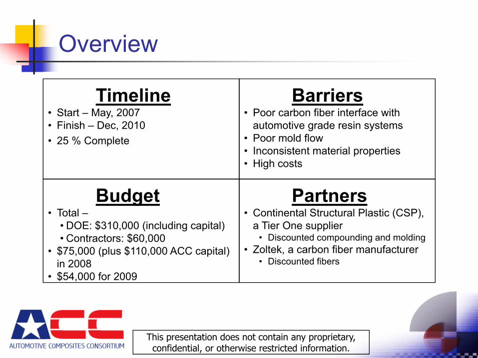
Timeline• Start – May, 2007• Finish – Dec, 2010• 25 % Complete
Budget• Total –
• DOE: $310,000 (including capital)• Contractors: $60,000
• $75,000 (plus $110,000 ACC capital) in 2008
• $54,000 for 2009
Partners• Continental Structural Plastic (CSP),
a Tier One supplier• Discounted compounding and molding
• Zoltek, a carbon fiber manufacturer• Discounted fibers
Barriers• Poor carbon fiber interface with
automotive grade resin systems• Poor mold flow• Inconsistent material properties• High costs
This presentation does not contain any proprietary, confidential, or otherwise restricted information.
Objectives
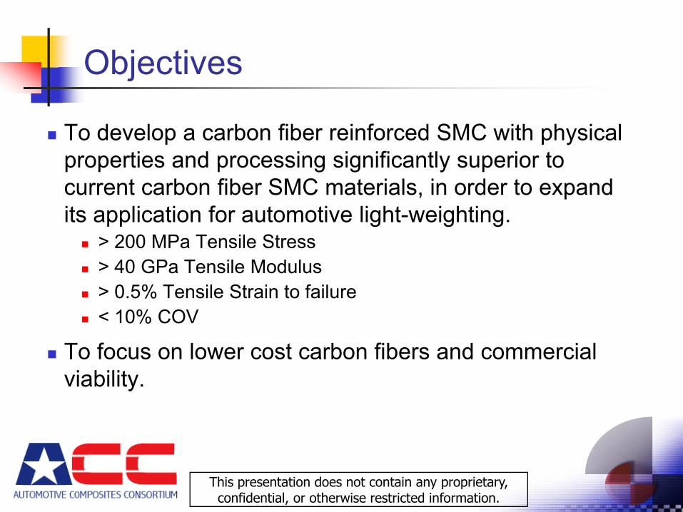
To develop a carbon fiber reinforced SMC with physical properties and processing significantly superior to current carbon fiber SMC materials, in order to expand its application for automotive light-weighting.
> 200 MPa Tensile Stress> 40 GPa Tensile Modulus> 0.5% Tensile Strain to failure< 10% COV
To focus on lower cost carbon fibers and commercial viability.
This presentation does not contain any proprietary, confidential, or otherwise restricted information.
Approach
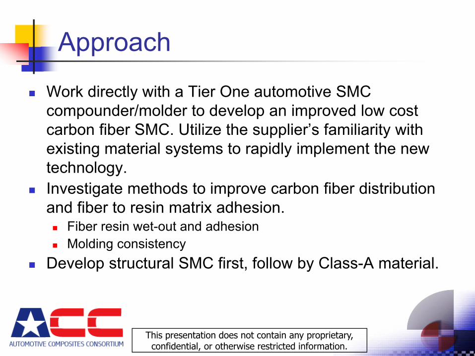
Work directly with a Tier One automotive SMC compounder/molder to develop an improved low cost carbon fiber SMC. Utilize the supplier’s familiarity with existing material systems to rapidly implement the new technology.Investigate methods to improve carbon fiber distribution and fiber to resin matrix adhesion.
Fiber resin wet-out and adhesionMolding consistency
Develop structural SMC first, follow by Class-A material.
This presentation does not contain any proprietary, confidential, or otherwise restricted information.
Milestones
Secure Tier One supplier Modify SMC compounder
FundingModification
Determine material goalsCompound baseline materialDevelop improved materialMold demonstration automotive part
This presentation does not contain any proprietary, confidential, or otherwise restricted information.
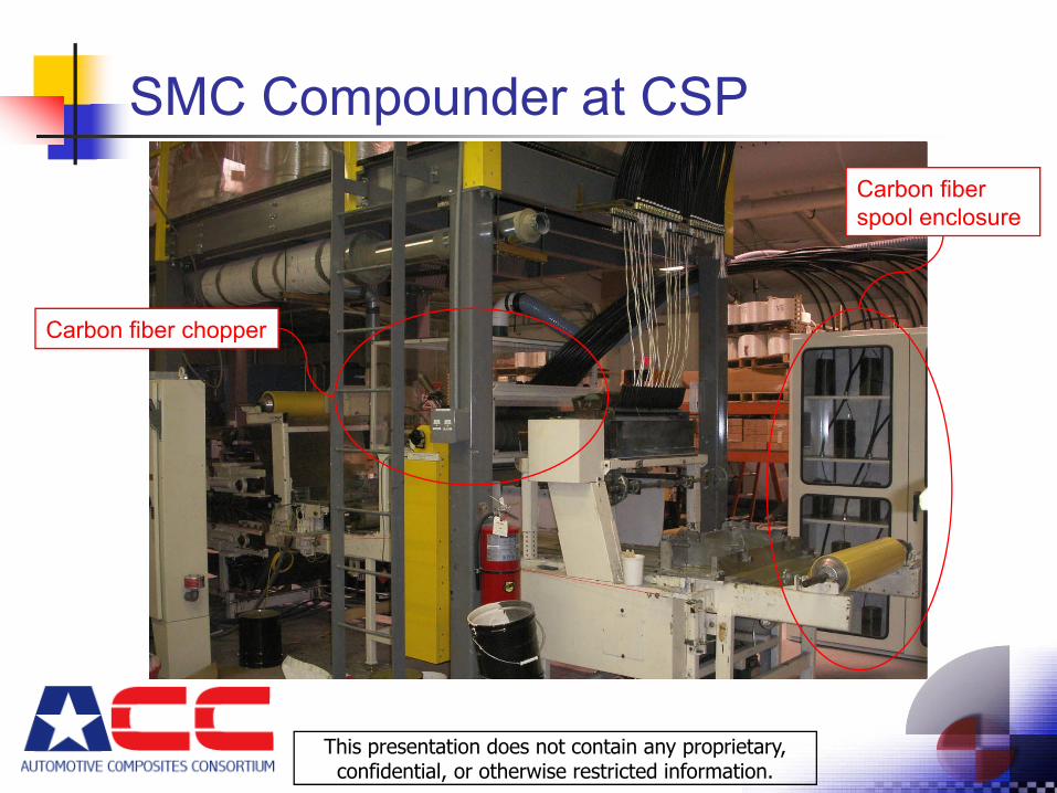
SMC Compounder at CSP
Carbon fiber chopper
Carbon fiber spool enclosure
This presentation does not contain any proprietary, confidential, or otherwise restricted information.
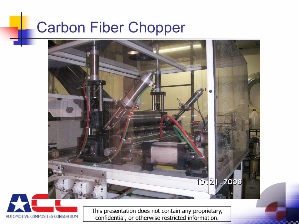
Carbon Fiber Chopper
This presentation does not contain any proprietary, confidential, or otherwise restricted information.
Technical Accomplishments – FY2008
• Existing glass fiber SMC compounder was successfully modified to chop carbon fibers. This includes safety features for dealing with air born carbon fibers.
• Completed testing of currently available carbon fiber SMC materials, used to set project targets for an improved material.
• Conducted fiber “sizing” study of Panex 35 carbon fibers, determined best initial sizing and amount of sizing to use with automotive vinyl ester resin systems.
This presentation does not contain any proprietary, confidential, or otherwise restricted information.
Future Work• Compound and test baseline SMC material.• Compound and test smaller tow carbon fibers to
evaluate fiber distribution and wet out.• Investigate methods to improve distribution and
wet-out of low cost/large tow carbon fibers.• Evaluate flow-ability of materials.• Modify successful structural materials for improved
surface appearance.• Investigate/compound current “fast” epoxy SMC
resin systems for comparison.
This presentation does not contain any proprietary, confidential, or otherwise restricted information.
Summary
Program targets were set to provide a commercially viable carbon fiber SMC material.CSP was selected as the Tier One supplier and their existing SMC compounder was upgraded to handle chopping of carbon fibers.An initial fiber sizing study was completed at Zoltek (the low cost carbon fiber supplier).
This presentation does not contain any proprietary, confidential, or otherwise restricted information.
ACC932 Materials and Processes Technology Development
Bond-Line Read-Through
5-20-09
Kedzie Fernholz
Ford
LM07
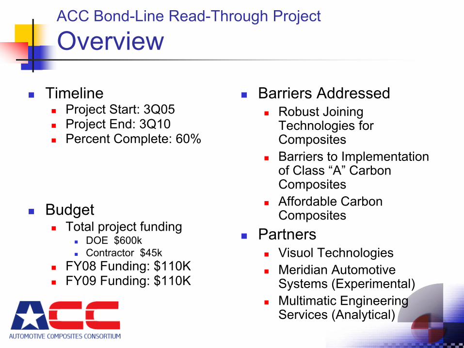
ACC Bond-Line Read-Through Project
Overview
TimelineProject Start: 3Q05Project End: 3Q10Percent Complete: 60%
BudgetTotal project funding
DOE $600kContractor $45k
FY08 Funding: $110KFY09 Funding: $110K
Barriers AddressedRobust Joining Technologies for CompositesBarriers to Implementation of Class “A” Carbon CompositesAffordable Carbon Composites
PartnersVisuol TechnologiesMeridian Automotive Systems (Experimental)Multimatic Engineering Services (Analytical)
ACC Bond-Line Read-Through Project
Objectives
FY08 Project ObjectivesPhase 1 – Measurement Development
Evaluate and Refine Algorithm Converting Raw Data to Meaningful Quantitative Value
Phase 2 – Determine BLRT Root CauseFY08 Experiments
Initial Factor Screening ExperimentsEffect of Cure Temperature ExperimentEffect of Adhesive Volume ExperimentsFlange Coverage Experiment
Project ObjectiveDevelop the ability to predict bond-line read-through in the design phase to enable use of minimum thickness closure panels
ACC Bond-Line Read-Through Project
FY08 Milestones
Phase 1 – Measurement DevelopmentDemonstrate the developed measurement algorithm is applicable to experimental panelsDetermine repeatability and reproducibility of the measurements.
Phase 2 – Determine BLRT Root CauseIdentify factors with a high impact on BLRT severityIdentify at least two factors with a minimal impact on BLRT severity
ACC Bond-Line Read-Through Project
Approach
Phase 1 – Measurement DevelopmentDevelop a measurement technique that quantifies the visual severity of surface distortions caused by bond-line read-through in a way that correlates with visual assessments
Phase 2 – Determine BLRT Root CauseExperimentally determine which material and process factors are the primary contributors to BLRT-induced distortionsCreate experimental data to validate analytical models
Phase 3 – Develop an Analytical Model for Predicting BLRT
Determine the material properties and analytical modeling techniques necessary to predict BLRT-induced distortionsIdentify design principles to minimize the occurrence of BLRT and allow OEMs to use minimum thickness outer panels in closures
ACC Bond-Line Read-Through Project
FY08 Technical Accomplishments
Phase 1Algorithm demonstrated to successfully quantify BLRT distortions on experimental assemblies Repeatability & reproducibility of overall system found to be inadequate
Assemblies are measured three times to improve data Evaluation of a more “production representative” system to occur in FY09
Phase 2Completed initial screening experiment, including analysisCompleted initial follow-up experiments, including analysis
Effect of Cure Temperature ExperimentEffect of Adhesive Volume ExperimentsFlange Coverage Experiment
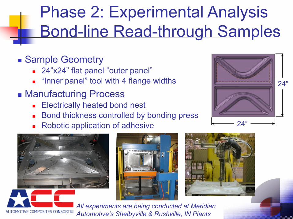
Phase 2: Experimental Analysis Bond-line Read-through Samples
Sample Geometry24”x24” flat panel “outer panel”“Inner panel” tool with 4 flange widths
Manufacturing ProcessElectrically heated bond nestBond thickness controlled by bonding pressRobotic application of adhesive
All experiments are being conducted at Meridian Automotive’s Shelbyville & Rushville, IN Plants
24”
24”
Phase 2: Experimental Analysis
Screening Experiment Results
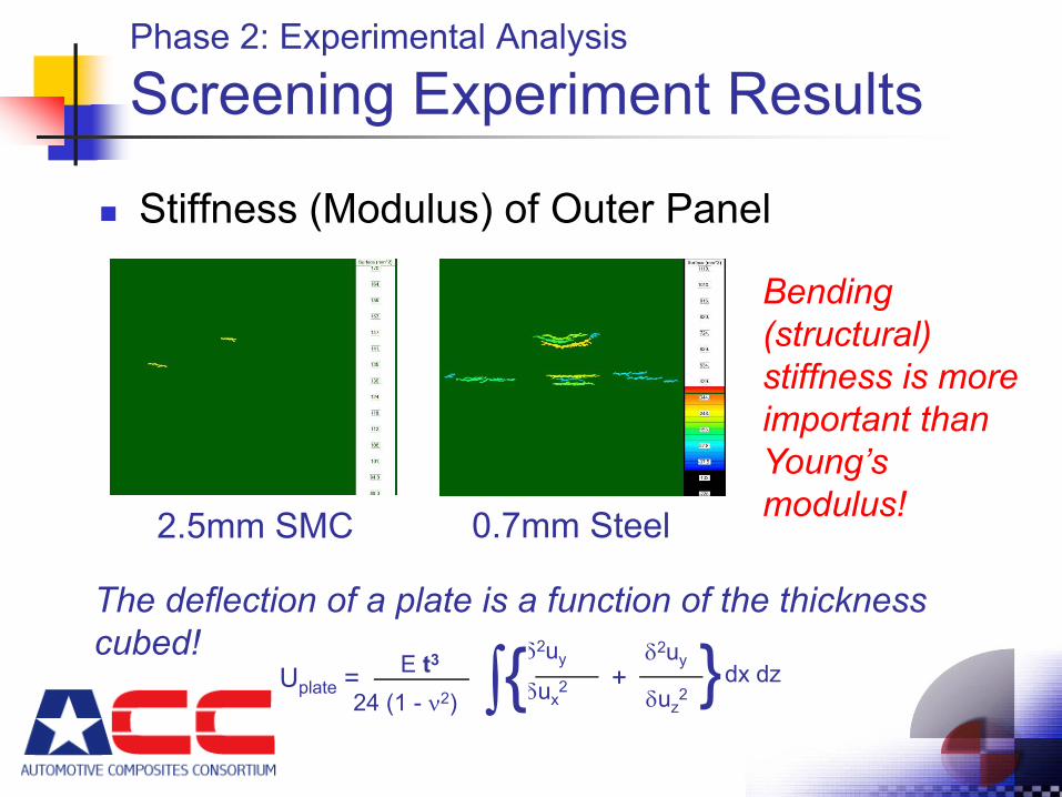
Stiffness (Modulus) of Outer Panel
0.7mm Steel2.5mm SMC
Bending (structural) stiffness is more important than Young’s modulus!
The deflection of a plate is a function of the thickness cubed!
dx dzE t3
24 (1 - ν2)}δ2uy
δux2
δ2uy
δuz2
+Uplate = {∫
Phase 2: Experimental Analysis
Screening Experiment Results
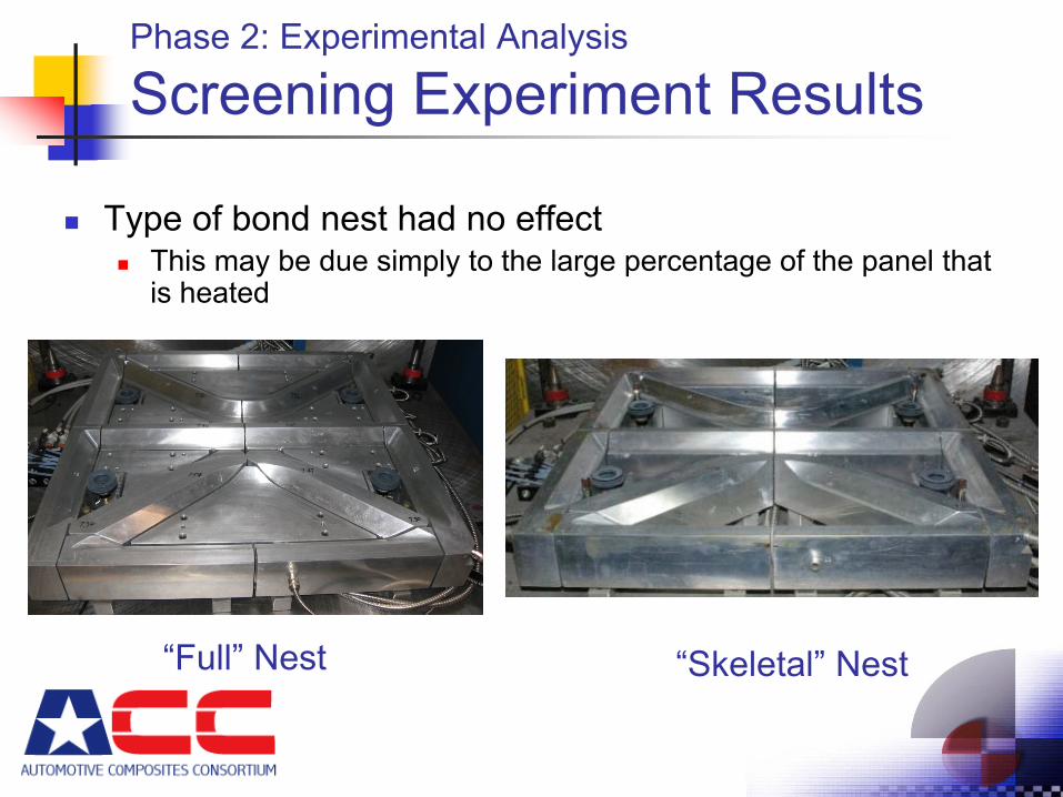
Type of bond nest had no effectThis may be due simply to the large percentage of the panel that is heated
“Skeletal” Nest“Full” Nest
Phase 2: Experimental Analysis
Screening Experiment Results
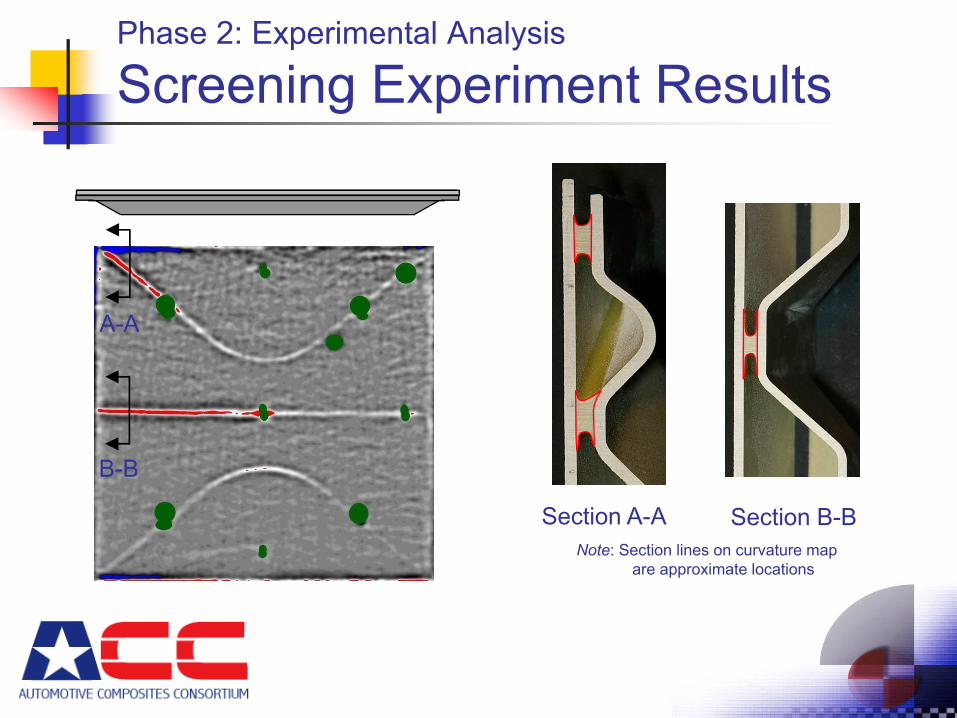
Section A-A
A-A
B-B
Section B-BNote: Section lines on curvature map
are approximate locations
Phase 2: Experimental Analysis
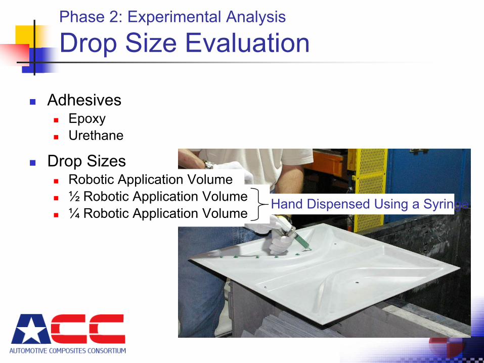
Drop Size Evaluation
Hand Dispensed Using a Syringe
AdhesivesEpoxyUrethane
Drop SizesRobotic Application Volume½ Robotic Application Volume¼ Robotic Application Volume
Phase 2: Experimental Analysis
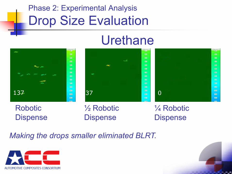
Drop Size Evaluation
Robotic Dispense
½ Robotic Dispense
¼ Robotic Dispense
137
137
37
3700
Urethane
Making the drops smaller eliminated BLRT.
Phase 2: Experimental Analysis
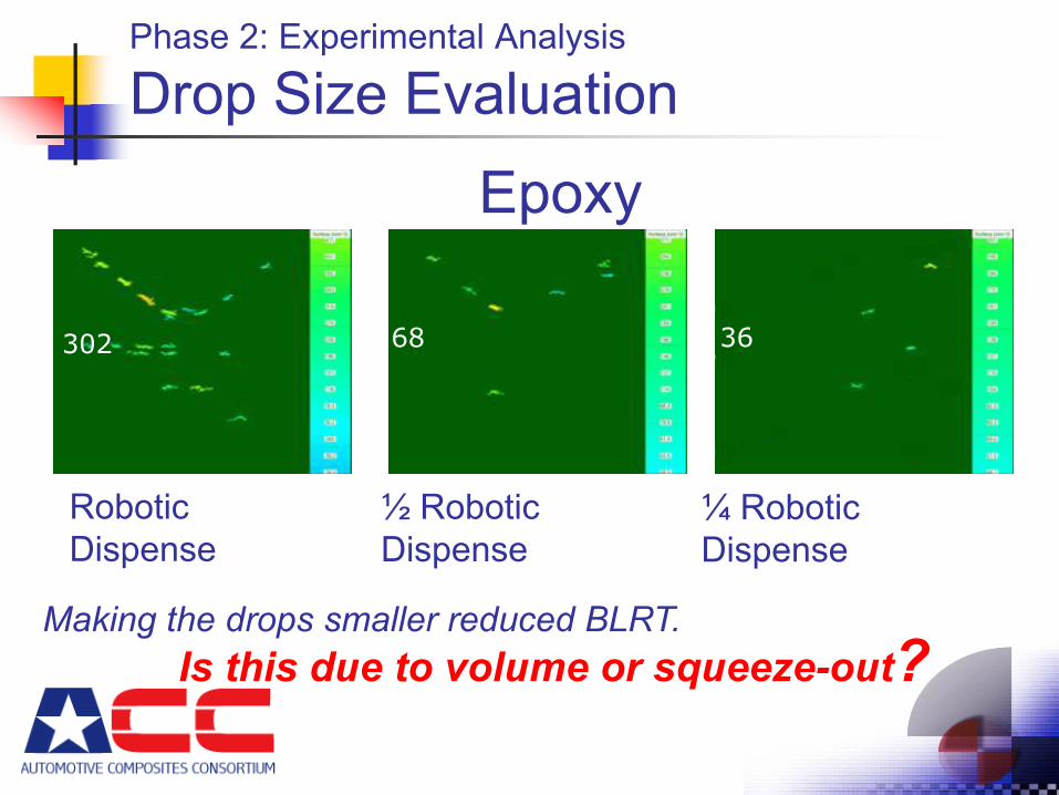
Drop Size Evaluation
Robotic Dispense
½ Robotic Dispense
¼ Robotic Dispense
Epoxy
302 68 36
Is this due to volume or squeeze-out?Making the drops smaller reduced BLRT.
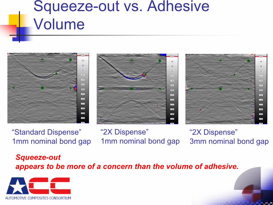
Squeeze-out vs. Adhesive Volume
“Standard Dispense”1mm nominal bond gap
“2X Dispense”1mm nominal bond gap
“2X Dispense”3mm nominal bond gap
Squeeze-out appears to be more of a concern than the volume of adhesive.
Phase 2: Experimental Analysis
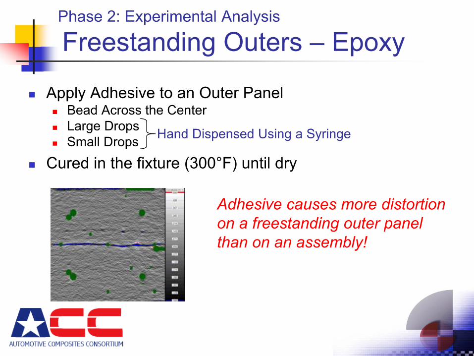
Freestanding Outers – Epoxy
Apply Adhesive to an Outer PanelBead Across the CenterLarge DropsSmall Drops
Cured in the fixture (300°F) until dry
Hand Dispensed Using a Syringe
Adhesive causes more distortion on a freestanding outer panel than on an assembly!
ACC Bond-Line Read-Through Project
Future Work
Evaluate Variations on Measurement System Hardware to Improve Repeatability & ReproducibilityComplete Additional Experiments
Mastic screeningPanel density and inner panel thicknessGenerate experimental data to validate CAE model development
Begin Development of Analytical ModelsDevelop a validated model for BLRT on a freestanding outerDevelop a validated model for BLRT on a “Basic” AssemblyDevelop a validated model for BLRT caused by Stand-offs on the inner panel bond flangeUse the model to explore the effectiveness of different design strategies
ACC Bond-Line Read-Through Project
Summary
Surface distortions caused by BLRT can now be quantitatively measuredExperimental data generated in this project has identified several key material and process factors for which analytical models must accountThe ability to predict BLRT will allow OEMs to immediately reduce closure outer panel thickness (and therefore WEIGHT) by 25%.This technology will allow the use of minimum thickness panels when Class “A” carbon fiber SMC becomes technically and financially viable.