Embed Size (px)
Citation preview

The 7th International Conference on Power ElectronicsOctober 22-26, 2007 / EXCO, Daegu, Korea
Case study of distrubution-unified power flow controller (D-UPFC) in the clustered PVsystem
Kyungsoo Lee, Kenichiro Yamaguchi, and Kosuke KurokawaTokyo University ofAgriculture and Technology
Department ofElectronics and Information Engineering2-24-16, Naka-cho, Koganei, Tokyo, 184-8588 Japan
Email: [email protected]@[email protected]
WEE2·2
Abstract-This paper shows the case study of D-UPFC in theclustered PV system. D-UPFC mainly controls distributionvoltage and thus, it is installed in the low-voltage distributionsystem connects with clustered PV system. Proposed D-UPFCtopology is shown and compared with existing topology. Theproposed topology can decrease the transformer capacitycompared with existing topology. In the case study, voltagecontrol and dynamic characteristic of D-UPFC are analyzed.Forward power flow, reverse power flow, and load power factorchange conditions are simulated using ATP-EMTP tool.
I. INTRODUCTION
In the power flow condition, faults occuring in powerdistribution systems or facilities in plants generally cause thevoltage sags or swells. Also, power systems supply power fora wide variety ofdifferent user applications, and sensitivity tovoltage sags and swells varies widely for differentapplications [1].
A few voltage control methods have been developed.Static var compensator (SVC) regulates over- andunder-voltage conditions by controlling its reactive power.Autotransformer with line drop compensator based stepvoltage regulator (SVR) selects suitable voltage using aswitch during voltage change. Also, scheduled operationcontrols distribution line voltage in the substation [2].
These voltage control methods concerns during forwardpower flow condition. Also, they are performed not thelow-voltage distribution system but the high-voltagedistribution system.
Reverse power flow happens when clustered PV systemconnects with distribution system. Voltage increasephenomenon happens due to reverse power flow. When thevoltage increase occurs in the low-voltage distributionsystem, it affects to stop generating power from clustered PVsystem or to trouble distribution system equipments.
This paper shows the case study of D-UPFC in thedistribution system. D-UPFC is a voltage controller in thelow-voltage distribution system. When the voltage decreaseis happened due to load consumption power low, D-UPFCcontrols the voltage rapidly. Also, when voltage increasecondition due to reverse power flow from clustered PVsystem occurs, D-UPFC regulates the distribution voltage.
Proposed D-UPFC topology is compared with existingD-UPFC topology. Proposed topology can decreasetransformer size, weight, and capacity because it uses only
978-1-4244-1872-5/08/$25.00 ©2008 IEEE
one secondary side winding. Using this proposed topology,the case study of the distribution model is performed.Distribution voltage control during RL load condition andreverse power flow condition is simulated. The dynamicvoltage control due to load power change and reverse powerflow is also verified using ATP-EMTP software.
II. D-UPFC THEORY
A. Proposed TopologyD-UPFC consists of transformer and bi-directional ac-ac
converter in the low-voltage distribution system. Thetransformer of the existing D-UPFC topology is divided oneprimary side and two secondary sides. Bi-directional ac-acconverter is connected in the upper side ofthe secondary. Fig.1 shows the existing D-UPFC topology [2,3].
Fig. 1: Existing D-UPFC topology
D-UPFC output voltage equation can be expressed,
N 2 +(DxN3)Vout = xVs = Vir1 +(DXVir2) = Vir1 + Vir2 0 (1)
N1
Where, D is duty ratio ofthe bi-directional ac-ac converter.Transformer of the proposed topology is divided one
primary side and one secondary side. Tap voltage N)' ofprimary side is added to secondary side voltage. It is similarto auto-transformer topology. Proposed D-UPFC topology isshown in Fig. 2.
D-UPFC output voltage equation can be expressed,
835
Authorized licensed use limited to: UNIVERSIDADE DO PORTO. Downloaded on May 06,2010 at 15:57:47 UTC from IEEE Xplore. Restrictions apply.

The 7th International Conference on Power ElectronicsOctober 22-26, 2007 / EXCO, Daegu, Korea
,----I ,..---------,
I
N2IIII~
N1
N1'
VM r
I IID-VPFC I1 ..J
Considering the clustered PV system connects withlow-voltage distribution system~ the power flow and loadpower factor should be changed. Forward power flow ~
reverse power flow and load power factor change can beexpressed using phase diagram. Fig. 5 shows the phasediagram of input voltage and output current relation in thebi-directional ac-ac converter.
C/oad
Fig. 2: Proposed D-UPFC topology
Transformer turn ~ s ratio N] , is the tap which is located inthe primary side, Thus~ Proposed D-UPFC topology candecrease the transformer size~ weight and capacity comparedwith the existing topology.
26Reverse power flow Forward power flow
-6 low =low LOc VtT '1 =~;"2LOc
Rload
Bi-directional ac-ac converter from the Fig. 2 is shown inFig.3. The equation of this converter is~
Fig. 3: Bi-directional ac-ac converter circuit
L load
Fig. 5: AC-AC converter input voltage and output current phase diagramconsidering power flow and load power factor
III. CASE STUDY
D-UPFC voltage control in the low-voltage distributionsystem is shown. Voltage decrease and increase control aresimulated considering load power factor change. D-UPFCdynamic voltage control also simulated using ATP-EMTP.
r-----
: Input filter I_____ J
r-----
Vtr2
Fig. 4: D-UPFC voltage control block
B. Voltage Control MethodD-UPFC input voltage Vin is always controlled by
reference voltage V1'4 de' Vin is changed from ac to dc throughRMS function. V1'~l de is 202[V~rms]~ which is low-voltagedistribution system voltage. Error voltage Ve1'ro1' between Vin
and Vr~(de is through PI compensator. VreLduty which is thereference duty of ac-ac converter is added to Ve"rror pi' ~~wm
compares with Vlri in the PWM function. Switches S"d to Sw4are operated by PWM function. D-UPFC voltage controlblock is shown in Fig. 4.
(b) Node All to A24 of the distribution model
Fig. 6: Distribution model for voltage decrease condition in the RL load
(a) Node A5 to A8 of the distribution model
(3)
S,.,I,JS,.,1.4
~r2_o =Dx Vtr2
Bi-directional ac-ac converter can directly transfer acpower to ac power without large energy storage devices. Also~it can control the voltage during power flow change and loadchange conditions. These conditions are realized using theswitching patterns [3~ 4].
D-UPFC simulation models are shown in Fig. 6 and 7.They are assumed the residential area of Japan. Detailedmodel explanation is shown in reference [2]. Fig. 6 showsvoltage decrease model due to heavy load condition.
836
Authorized licensed use limited to: UNIVERSIDADE DO PORTO. Downloaded on May 06,2010 at 15:57:47 UTC from IEEE Xplore. Restrictions apply.

The 7th International Conference on Power ElectronicsOctober 22-26, 2007 / EXCO, Daegu, Korea
A22 A23Node number
95 L....-__..I....-__....&..-_--.;;;;;:::.
A21
(d) D-UPFC control at An
(b) D-UPFC control at A2l
_100
199~l'I98 -Ig 97
A22 A23Node number
_100
~ 99~l'I98JJg 97
102P_=_-==~===------:-__-J
A6 A7Node number
95 '--__..1....-__....&..-__.....
A5
(a) D-UPFC control at A5
(c) D-UPFC control atA6
95 L....-__....... --I
A5
.. 100
: 99
E 98
g 97
" L _I I
A. Voltage decrease controlVoltage decrease control is shown in Fig. 8. These
simulation results are performed when heavy load isconnected to the distribution system. Heavy load parametersare shown in Table 1.
(b) Node A21 to A24 of the distribution model
Fig. 7: Distribution model for voltage increase condition in the RL loadwith clustered PV system
D-UPFC installation is shown from Aj to A8 of Tr], from A2l
to A24 of Tr6 pole transformer.
(a) Node A5 to A8 of the distribution model
Fig. 7 shows the voltage increase model due to reversepower flow from clustered PV system. D-UPFC installationis shown from Aj to A8 of Tr2' from A2J to A24 of Tr6 poletransformer.
Table 1 shows the distribution model parameters. Powerfactor is assumed 0.9 in the RL load condition. Capacity ofaPV system is regarded as 3[kW].
_100
l 99~i 98
g 97
95 '---------......1-.----'A5
(e) D-UPFC control atA 7
101
_100
l 99
~i 98
g 97
A22 A23Node number
(0 D-UPFC control at A23
Fig. 8: Voltage decrease control in the RL load condition
A22 A23Node number
94 '--__.....l-...__-'--__......
A21
(h) D-UPFC control atA24
102101 I~"":'=~==::------:- __----l
_100
~ 99
~ 98 -
! 97
> 96
(g) D-UPFC control at A8
95 L....-__....... --'
A5
_100
l 99
~i 98
: 97
TABLE 1. Distribution model parametersSubstation 66kV/6.6kV, 20MVAPole transformer 6.6kV/202V(lOl V), 50kVAHV line impedance(Z] to Z5) O.626+jO.754[O/2km]LV line impedance(Zdl to Zd3) 0.025+jO.020[n/40mlLead-in wire imp.(Zil to 2;20) 0.0552+jO.037[n/20m]
Total loadI Light load 4.08+j2.028[n] (p.f. 0.9)I Heavy load 1.02~jO.507rn] (p.f. 0.9)
Each PV power 3[kW]
D-UPFC parameters are shown in Table 2. The maximumD-UPFC voltage control range is ±20.2[V,rms] fromtransformer voltage tap N2• Input and output LC filters reduceinput current and output voltage harmonics [5]. D-UPFCoutput is the same as distribution system voltage 202[V,rms]during normal mode.
TABLE 2 D-UPFC parametersVs 202[V,rms] Cin & Cout 50ruFlN}:N}':N2 1:0.9:0.2 Vrefdc 202[V,rmsl
Vtr} 181.8[V,rms] PI gainKp=0.025Ki=O.OOl
Vtr2 40.4[V,rms] Switching freq. 20rkHz]Lin & Lout 50[Jili] Vrefdutv 0.5
As the Fig. 6, D-UPFC is installed in the secondary of thepole tramsformer. The low-voltage distribution voltage rangeis 202±20 (101±6)[V,rms]. Fig. 8 shows the 100[V,rms] lineresults. Before the D-UPFC control voltage decrease fromnode A j (a) to A8 (g) is from 100.3[V,rms] to 96.5[V,rms],respectively. However, D-UPFC controls 100.7[V,rms] to100.8[V,rms] from node A j to A8, respectively. Also, voltagedecrease from node A2J (b) to A24 (h) is from 99[V,rms] to95.2[V,rms], respectively. These voltage decreases arecontrolled from 100.4[V,rIDs] to 100.9[V,rIDs], respectively.Thus, D-UPFC controls distribution voltage to referencevoltage at the installation site.
837
Authorized licensed use limited to: UNIVERSIDADE DO PORTO. Downloaded on May 06,2010 at 15:57:47 UTC from IEEE Xplore. Restrictions apply.

The 7th International Conference on Power ElectronicsOctober 22-26, 2007 / EXCO, Daegu, Korea
(a) D-UPFC inner voltage VtrI, Vtr2 , Vtr2 0A22 A23
Node number
- ~105
~.104;;.1103
~102
A6 ATNode number
100 '----"""'------'-------'A5
~105
E"'104;;.1103
~102
B. Voltage increase controlFig. 10 shows the D-UPFC voltage control during voltage
increase from PV reverse power flow. As shown in Table Iand 2, parameters are used in the simulation. Voltageincrease from node Aj (a) to A8 (g) is 101 [V,rms] toI05.3[V,nns], respectively. These node voltages arecontrolled through D-UPFC from 10I.3[V,nns] to101.1 [V,nns], respectively. Also, voltage increase from nodeAn (b) to A24 (h) is IOI.3[V,rms] to 105.6[V,nns],respectively. D-UPFC controls the voltages fromIOI.5[V,rms] to IOI.3[V,nns], respectively. From the Fig. 10,D-UPFC controls the distribution voltage at the installationsite as the voltage decrease control.
[s] 0.500.44O'(~;eU-,(YU5~':
-300+--r---.....-~---.--.....--..------,r--~--.....---l
0.40 0.42(filecludllired_helWY_testI04.pI4;,.,.-vart)
Fig. 9 shows D-UPFC inner voltage (Vtr], Vtr2, Vtr2_o ) ,
output voltage (Vout), output current (lout), and ac-ac conveterswitches (Swl to Sw-l) current wavefonns at node A2-1' Whenthe voltage decrease occurs caused by heavy load thebi-directional ac-ac converter output voltage Vtr2 0 increasesin the (a) of Fig. 9. D-UPFC output current phase lags tooutput voltage in the (b) of Fig. 9. Also, switches from Sw1 toSw4 show the current wavefonns without any problem in the(c) and (d) of Fig. 9.
[s] 0.50
A22 A23Node number
(b) D-UPFC control at A2l
(d) D-UPFC control at An(c) D-UPFC control at A6
(a) D-UPFC control at Aj
100 '----"""'------'-------'A5 A6 AT
Node number
...Rav..... power•• Rlload wilt no control"'VoIagecOlllrolatM 1____ -I 1. I
1 1~105 - - - - -I - - - - - - - -I ~105
~104 -----1--- _1. 1 ~104;;. 1 1 ;;.
f::: - - f:::
-350.0+--.----,---r---r--...,......-----,r----,-----.----.--~
0.40 0.42(f Iie c luate re cth eavy_te Itt ~ 04.pl4 )(-\1ar t)
350.0-.------------------_
(c) AC-AC converter switch S'o1'I, .S'o1'3
(b) D-UPFC output voltage ~llIt, output current lout
A22 A23Node number
A22 A23Node number
(h) D-UPFC control at A24
(0 D-UPFC control at A23
A6 ATNode number
A6 ATNode number
100 '--__...J.-__--'-__---J
A5
100 '----"""'------'-------1A5
(e) D-UPFC control atA 7
(g) D-UPFC control at As
-+oRn power •• Rlload.1It no control...Vo coatrol.tA7 1_____I L 1
1
~105 - - - - -I - - - - -E-·104 - - - - -I __ - _;;. 1
lJl103
~102 -
~105
~104;;.i 103
>102 -
k 0.4070
II I: I •
-80+--r------r----r-----.---r---r---..--------.----.--___l0.4060 0.4062
(flkcluste redJ'!eavv_testl04.pt4x.-vari:
SW3-40
80-.---------------------,
[A]
60V / / / rl' ~i/ /' /' /11/ // // /'-S 40 I
wI . I
Sw2 40
80....---------------------.
[A]
60
Fig. 10: Voltage increase control in the reverse power flow condition
ls. 0.4070-80+---...-------r----r-----.---r---r---..----~-____._-___l
0.4060 0.4062(fileciustft redJ' eavv_testlD4.pt4:)(-vart;
(d) AC-AC converter switch Sw2, S'o1'''
Fig. 9: Voltage and current waveforms during voltage decrease at A2"
Fig. II shows D-UPFC inner voltage (Vtrl , Vtr2, Vtr2 0)'output voltage (Vout), output current (lout), and ac-ac conveterswitches (Swl to Sw4) current wavefonns at node A2-1' In theD-UPFC control, ac-ac converter output voltage Vtr2 0 isdecreased in the (a) of Fig. 11. The second wavefonns s-howthe V~ut and lout of D-UPFC. Here, lout phase is 1800 different
838
Authorized licensed use limited to: UNIVERSIDADE DO PORTO. Downloaded on May 06,2010 at 15:57:47 UTC from IEEE Xplore. Restrictions apply.

The 7th International Conference on Power ElectronicsOctober 22-26, 2007 I Exeo, Daegu, Korea
from V out due to reverse power flow condition. Even thoughthe load power factor is 0.9, lout is not affected by load currentbecause PV output current was large and grid-connected.
Switches which are from Swl to Sw4 current waveforms (c)and (d) ofFig. 11 perform with no problem during operation.
power and PV reverse power. Thus, D-UPFC should controlthis rapid voltage change in order to prevent voltage problemin the distrution line. Dynamic voltage control during thevoltage decrease condition is shown in Fig. 12.
[s] 0.46
[s] 0.46190+-----,r-----r--..---.,...-----,----.---..---.,...-----,r----1
0.26 0.30 0.34(f,!eclu.tered_h.oYy_te.U1-"""id.pl4;.....,.rt)tXX0677
-300+-----,r--~--.----r----r-__r_--.---r------r--1
0.26 0.30 0.34 0.38Ifle clu.ter.d..h.oYy_lIost11_rapid.ol4;.....,.rtl v.XX0465 cXXD465-XXOORI
(a) D-UPFC input voltage ViII_de
(b) D-UPFC output voltage Vou(, output current lout[s] 0.50
[s] 0.500.48
0.46
-300+-----,r-----r--..---~----,-_..,_-_r__-r_____r-__t
0.40 0.42(r.. "'v.".J'IhU..tl04.pl4;.....,artlvXX0733
-400+-----,r-----.-----r--~----,r-----r---.,...--~----.----1
0.40 0.42(lilor.v....._tirhU••tl04.pl4,.....,.rt) v;XX0104
(a) D-UPFC inner voltages Vh·1, Vt,.2, Vt,.2_0
300
[s] 0.46-50.o+-~---.---r------r-__r_--r-------,---.---.----t
0.26 0.30 0.34(f,!eclu.t."'d..h.oYy_test11_rapid.pl4; .......rf'cXX0395-XXD457
-37.5
50.0.---=---~------------....,
[A]
37.5
100.---------------------,
[A]
////////////////////
(b) D-UPFC output voltage Vour, output current lout
S -50w3
[s] 0.4070-100+-----,-----r--_r__-r_____r---r--.------.-_..,_---;
0.4060 0.4062 0.4064 0.4066(1,10 ",ver••_tirhUutl04.pl4 .......rt) c;XX0711-XX0607 (XXU6U9-XXU"'~,
(c) Substation current lsub, primary current of pole transformer lpr;
(c) AC-AC converter switch Swl, Sw3
100~-----------------,
[A]
75
[s] 0.4070
[.] 0.460.420.38O'O+--r----r-----r---r--r------r-__r_--.----r-~
0.26 0.30 0.34(fileclu.tered..he.yY_te.tl1_rapid.DI4;.-v.rtltXX0198
(d) AC-AC converter duty cycle
Fig. 12: Load consumption power change from 0.3[s] to O.4[s] andD-UPFC installation at node A6
-100+------,----r--.-------,----r---.---,r-----r---.----t0.4060 0.4062 0.4064 0.4066
(file "''''' ...._tirhU..tl04.pl4. .....,.rtl cXX0609-XX0607 cXX0617-XXD6':,
(d) AC-AC converter switch Sw2, Sw4
Fig. 11: Voltage and current waveforms during voltage increase at A24
c. Dynamic voltage controlRapid voltage change is always occurred in the
low-voltage distribution system due to load consumption
From the Fig. 6 (a), load consumption power changes4.9[kW] to 34.6[kW] between 0.3[s] and 0.4[s] at poletransformer. In the Fig. 12 (a), distribution voltage at node A6
changes 200.5 [V,rms] to 196.5[V,rms] during voltage
839
Authorized licensed use limited to: UNIVERSIDADE DO PORTO. Downloaded on May 06,2010 at 15:57:47 UTC from IEEE Xplore. Restrictions apply.
The 7th International Conference on Power ElectronicsOctober 22-26, 2007 / Exeo, Daegu, Korea
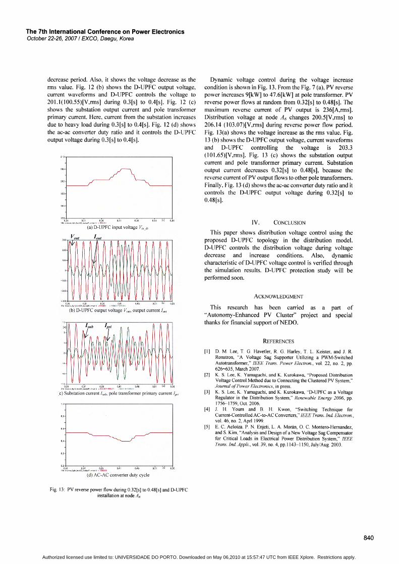
decrease period. Also, it shows the voltage decrease as therms value. Fig. 12 (b) shows the D-UPFC output voltage,current waveforms and D-UPFC controls the voltage to201.1(100.55)[V,rms] during 0.3[s] to 0.4[s]. Fig. 12 (c)shows the substation output current and pole transformerprimary current. Here, current from the substation increasesdue to heavy load during 0.3[s] to 0.4[s]. Fig. 12 (d) showsthe ac-ac converter duty ratio and it controls the D-UPFCoutput voltage during O.3[s] to 0.4[s].
Dynamic voltage control during the voltage increasecondition is shown in Fig. 13. From the Fig. 7 (a), PV reversepower increases 9[kW] to 47.6[kW] at pole transformer. PVreverse power flows at random from 0.32[s] to 0.48[s]. Themaximum reverse current of PV output is 236[A,rms].Distribution voltage at node A6 changes 200.5[V,rms] to206.14 (103 .07)[V,rms] during reverse power flow period.Fig. 13(a) shows the voltage increase as the rms value. Fig.13 (b) shows the D-UPFC output voltage, current waveformsand D-UPFC controlling the voltage is 203.3(101.65)[V,rms]. Fig. 13 (c) shows the substation outputcurrent and pole transformer primary current. Substationoutput current decreases 0.32[s] to 0.48[s], because thereverse current ofPV output flows to other pole transformers.Finally, Fig. 13 (d) shows the ac-ac converter duty ratio and itcontrols the D-UPFC output voltage during 0.32[s] to0.48[s].
ACKNOWLEDGMENT
REFERENCES
CONCLUSIONIV.
[1] D. M. Lee, T. G. Havetler, R. G. Harley, T. L. Keister, and J. R.Ronstron, "A Voltage Sag Supporter Utilizing a PWM-SwitchedAutotransformer," IEEE Trans. Power Electron., vol. 22, no. 2, pp.626-635, March 2007.
[2] K. S. Lee, K. Yamaguchi, and K. Kurokawa, "Proposed DistributionVoltage Control Method due to Connecting the Clustered PV System,"Journal q(Power Electronics, in press.
[3] K. S. Lee, K. Yamaguchi, and K. Kurokawa, "D-UPFC as a VoltageRegulator in the Distribution System," Renewable Energy 2006, pp.1756-1759, Oct. 2006.
[4] J. H. Youm and B. H. Kwon, "Switching Technique forCurrent-Controlled AC-to-AC Converters," IEEE Trans. Ind Electron.,vol. 46, no. 2, Aprl 1999.
[5] E. C. Aeloiza. P. N. Enjeti, L. A. Moran, O. C. Montero-Hernandez,and S. Kim, "Analysis and Design ofa New Voltage Sag Compensatorfor Critical Loads in Electrical Power Distribution System," IEEETrans. Ind Appli., vol. 39, no. 4, pp.1143-1150, July/Aug. 2003.
This paper shows distribution voltage control using theproposed D-UPFC topology in the distribution model.D-UPFC controls the distribution voltage during voltagedecrease and increase conditions. Also, dynamiccharacteristic of D-UPFC voltage control is verified throughthe simulation results. D-UPFC protection study will beperformed soon.
This research has been carried as a part of"'Autonomy-Enhanced PV Cluster" project and specialthanks for financial support ofNEDO.
0.51 [0] 0.56
(c) Substation current I.vub, pole transformer primary current Ipri
(a) D-UPFC input voltage Vin de
(b) D-UPFC output voltage VOllf' output current 10111
0.00+.26
--.....,0.3-1--0"T""".36--.......---~-----r'0.5-1---'[-=-0]----10
.56
!fitereverseJlrht_test22_rapid.pl4;K-varti t XX02B9
(d) AC-AC converter duty cycle
Fig. 13: PV reverse power flow during 0.32[s] to 0.48[s] and D-UPFCinstallation at node A6
840
Authorized licensed use limited to: UNIVERSIDADE DO PORTO. Downloaded on May 06,2010 at 15:57:47 UTC from IEEE Xplore. Restrictions apply.